LPN-RH Installation Guide (Old type) - Intech Instruments Ltd
LPN-RH Installation Guide (Old type) - Intech Instruments Ltd
LPN-RH Installation Guide (Old type) - Intech Instruments Ltd

You also want an ePaper? Increase the reach of your titles
YUMPU automatically turns print PDFs into web optimized ePapers that Google loves.
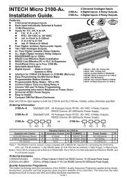
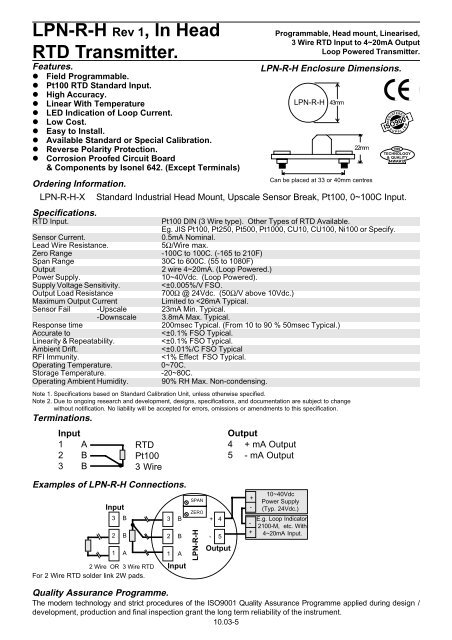
<strong>LPN</strong>-R-H Rev 1, In Head<br />
RTD Transmitter.<br />
Features.<br />
l Field Programmable.<br />
l Pt100 RTD Standard Input.<br />
l High Accuracy.<br />
l Linear With Temperature<br />
l LED Indication of Loop Current.<br />
l Low Cost.<br />
l Easy to Install.<br />
l Available Standard or Special Calibration.<br />
l Reverse Polarity Protection.<br />
l Corrosion Proofed Circuit Board<br />
& Components by Isonel 642. (Except Terminals)<br />
Programmable, Head mount, Linearised,<br />
3 Wire RTD Input to 4~20mA Output<br />
Loop Powered Transmitter.<br />
REGI STERED<br />
ISO9001<br />
S U<br />
P P<br />
I<br />
L<br />
R<br />
E<br />
1999<br />
TECHNOLOGY<br />
& QUALITY<br />
AWAR D<br />
Ordering Information.<br />
<strong>LPN</strong>-R-H-X Standard Industrial Head Mount, Upscale Sensor Break, Pt100, 0~100C Input.<br />
Specifications.<br />
RTD Input.<br />
Pt100 DIN (3 Wire <strong>type</strong>). Other Types of RTD Available.<br />
Eg. JIS Pt100, Pt250, Pt500, Pt1000, CU10, CU100, Ni100 or Specify.<br />
Sensor Current.<br />
0.5mA Nominal.<br />
Lead Wire Resistance.<br />
5Ω/Wire max.<br />
Zero Range -100C to 100C. (-165 to 210F)<br />
Span Range 30C to 600C. (55 to 1080F)<br />
Output<br />
2 wire 4~20mA. (Loop Powered.)<br />
Power Supply.<br />
10~40Vdc. (Loop Powered).<br />
Supply Voltage Sensitivity.<br />
<strong>LPN</strong>-R-H Programming.<br />
The Zero and Span can be set within the following values, as shown in the tables.<br />
Refer to PCB Layout for positions of solder pads on the <strong>LPN</strong>-R-H.<br />
S older Pad Z ero (C)<br />
Zero (F)<br />
A From -105 to -55C<br />
From<br />
-165<br />
to<br />
B From -55 to -5C<br />
From<br />
-65<br />
to<br />
C From -5 to 45C<br />
From<br />
25<br />
to<br />
D From 45 to 100C<br />
From<br />
115<br />
to<br />
65F<br />
25F<br />
115F<br />
210F<br />
S older Pad S pan (C)<br />
Span (F)<br />
1 From 30 to 65C<br />
From<br />
55<br />
to<br />
115F<br />
2 From 65 to 135C<br />
From<br />
115<br />
to<br />
245F<br />
3 From 135 to 280C<br />
From<br />
245<br />
to<br />
505F<br />
4 From 280 to 600C<br />
From<br />
505<br />
to<br />
1080F<br />
E.g. 1. If a range of -50~50C is required.<br />
E.g. 2. If a range of 200~600F is required.<br />
Zero = -50C. Solder Link 'B' <strong>LPN</strong>-R-H Zero = 200F. Solder Link 'D' <strong>LPN</strong>-R-H<br />
Span = 50--50 = 100C Solder Link '2' <strong>LPN</strong>-R-H Span = 600-200 = 400F Solder Link '3' <strong>LPN</strong>-R-H<br />
Note 1. Once the range has been programmed calibrate the <strong>LPN</strong>-R-H using the trimpots.<br />
Calibrate 0% = 4.00mA using the ZERO trimpot. Calibrate 100% = 20.00mA using the SPAN trimpot.<br />
Repeat Zero and Span calibrations until readings are correct. Check 50% = 12.00mA±0.016mA (±0.1% linearity)<br />
Note 2. If the range cannot be attained using the solder pads shown in the tables above, try the next solder pad closest<br />
to the value you require.<br />
Note 3. On the <strong>LPN</strong>-R-H any modified solder pads need to be coated with nail varnish or similar, to protect from corrosion.<br />
Upscale / Downscale Drive 'B' Selection for Sensor Break.<br />
Solder Link BOTH positions marked 'DS' for DOWNSCALE, or BOTH positions marked 'US' for UPSCALE.<br />
Two Wire '2W'.<br />
For 2 wire inputs, Solder Link the position marked '2W'.<br />
The Proper <strong>Installation</strong> & Maintenance of <strong>LPN</strong>-R-H.<br />
MOUNTING.<br />
(1) Mount in a clean environment in an approved industrial head.<br />
(2) Do not subject to vibration or excess temperature or humidity variations.<br />
(3) Avoid mounting in cabinets with power control equipment.<br />
(4) To maintain compliance with the EMC Directives the <strong>LPN</strong>-R-H is to be<br />
mounted in a fully enclosed metal head. The head must be properly<br />
earthed, with appropriate input / output entry points, filtering, and cabling.<br />
WIRING.<br />
(1) All cables should be good quality overall screened INSTRUMENTATION<br />
CABLE with the screen earthed at one end only.<br />
(2) Signal cables should be laid a minimum distance of 300mm from any<br />
power cables.<br />
(3) For 2 wire current loops Austral Standard Cables B5102ES is recommended.<br />
Location of <strong>LPN</strong>-R-H Solder Pads.<br />
For three wire transmitters and RTD's Austral Standard Cables B5103ES is recommended.<br />
(4) It is recommended that you do not ground current loops and use power supplies with ungrounded outputs.<br />
(5) Lightning arrestors should be used when there is a danger from this source.<br />
(6) Refer to diagrams for connection information.<br />
RTD'S.<br />
(1) Avoid locating the RTD where it will be in a direct flame.<br />
(2) Locate it where the average temperature will be measured. It should be representative of the mass.<br />
(3) Immerse the RTD far enough so that the measuring point is entirely in the temperature to be measured; nine to<br />
ten times the diameter of the protection tube is recommended. Heat that is conducted away from the measuring<br />
point causes a lower reading.<br />
COMMISSIONING.<br />
(1) Once all the above conditions have been carried out and the wiring checked apply power to the <strong>LPN</strong>-R-H loop and<br />
allow five minutes for it to stabilize.<br />
(2) Due to differences in cable resistance in the RTD legs or errors within the RTD itself a small Zero error may occur<br />
(usually less than 0.5°C). To remove this error use a calibration standard RTD at the same immersion depth and<br />
adjust the Zero trimpot on the top of the <strong>LPN</strong>-R-H enclosure with a small screwdriver, until the two levels agree.<br />
(Clockwise to increase the output reading and anticlockwise to decrease the output reading)<br />
MAINTENANCE.<br />
(1) Check RTD's in place - with a calibration RTD at the same immersion depth.<br />
(2) Do it regularly - at least once every 6 months.<br />
(3) Replace defective protection tubes - even if they look good they may not be air or gas tight.<br />
(4) Check cables entering the RTD sensor head.<br />
(5) Keep rotary switches clean and free of oxidisation of contact points.<br />
Note: This is looking at the<br />
BOTTOM of the <strong>LPN</strong>-R-H board.<br />
2WIRE:<br />
2W<br />
US<br />
DS<br />
ZERO: ZABCD<br />
SPAN: 4321S<br />
US<br />
DS<br />
B<br />
:SENSOR<br />
BREAK<br />
<strong>Intech</strong> INSTRUMENTS LTD.<br />
Christchurch Auckland<br />
Ph: 03 343 0646 Ph: 09 827 1930<br />
www.intech.co.nz<br />
Fx: 03 343 0649 Fx: 09 827 1931<br />
10.03-6<br />
lpn-r-h.p65<br />
ISSUE 050104