2300-Tc8 - MODBUS supplementary manual
2300-Tc8 - MODBUS supplementary manual
2300-Tc8 - MODBUS supplementary manual

You also want an ePaper? Increase the reach of your titles
YUMPU automatically turns print PDFs into web optimized ePapers that Google loves.
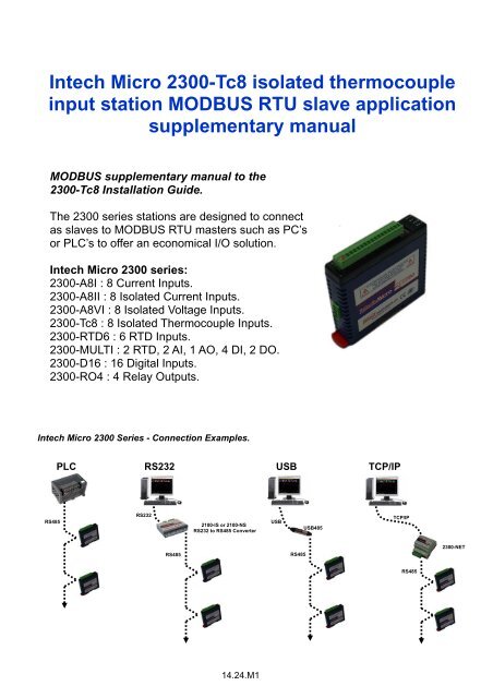
Intech Micro <strong>2300</strong>-<strong>Tc8</strong> isolated thermocoupleinput station <strong>MODBUS</strong> RTU slave application<strong>supplementary</strong> <strong>manual</strong><strong>MODBUS</strong> <strong>supplementary</strong> <strong>manual</strong> to the<strong>2300</strong>-<strong>Tc8</strong> Installation Guide.The <strong>2300</strong> series stations are designed to connectas slaves to <strong>MODBUS</strong> RTU masters such as PC’sor PLC’s to offer an economical I/O solution.Intech Micro <strong>2300</strong> series:<strong>2300</strong>-A8I : 8 Current Inputs.<strong>2300</strong>-A8II : 8 Isolated Current Inputs.<strong>2300</strong>-A8VI : 8 Isolated Voltage Inputs.<strong>2300</strong>-<strong>Tc8</strong> : 8 Isolated Thermocouple Inputs.<strong>2300</strong>-RTD6 : 6 RTD Inputs.<strong>2300</strong>-MULTI : 2 RTD, 2 AI, 1 AO, 4 DI, 2 DO.<strong>2300</strong>-D16 : 16 Digital Inputs.<strong>2300</strong>-RO4 : 4 Relay Outputs.Intech Micro <strong>2300</strong> Series - Connection Examples.PLCRS232USBTCP/IPRS485RS2322100-IS or 2100-NSRS232 to RS485 ConverterUSBUSB485TCP/IPRS485RS485<strong>2300</strong>-NETRS48514.24.M1
<strong>2300</strong>-<strong>Tc8</strong> Specifications.TC Inputs: -Input Points 8-Resolution0.1°C-Drift100ppm/°C-Isolation1500Vrms between field and logicTC Type: -Number Type Range Accuracy-1 J -150 to 760°C ± 0.2°C-2 K -200 to 1370°C ± 0.3°C-3 E 0 to 600°C ± 0.1°C-4 T -200 to 400°C ± 0.3°C-5 N 0 to 1300°C ± 0.3°C-6 B 400 to 1820°C ± 0.5°C-7 S -50 to 1767°C ± 0.6°C-8 R -50 to 1767°C ± 0.7°C-9 mV 0 to 50mV ± 0.1°C-10 C 0 to 2315.5°C ± 0.7°C-11 D 0 to 2315.5°C ± 0.7°C-12 G 0 to 2315.5°C ± 0.9°C-13 mV +/- 100mV ± 0.1%Cold Junction: -CJC Error ± 0.5°C Typ. After 30 minutes warm up timeConnectors: -Logic Power and Comms 4 Pin plug-in connector on side of station-Inputs18 Way screw plug-in connector on top of stationComms: -Protocols RS485, Modbus RTU-Baud Rate 2400, 4800, 9600, 19200, 38400, 57600, 115200-FormatParity: 0 = none, 1 = even, 2 = oddStop Bits: 1 = 1 stop bit, 2 = 2 stop bitsPower Supply: -Logic Supply Voltage 12~24Vdc-Logic Supply Current 58mA @ 12V / 31mA @ 24VSafety and EMC Compliances:EMC Compliance 89/336/EEC and Low Voltage Equipment Directive 73/23/EECSafety Compliance IEC 950General Specifications: (Unless otherwise stated in other input specifications).Operating Temperature-10~50˚CStorage Temperature-40~85˚COperating HumidityUp to 95% non condensingHousing -Dimensions L=97.5, W=22.6, H=109mm-Mounting35mm Symmetrical Mounting Rail.Note 1. Contact INTECH INSTRUMENTS for more detailed programming information.Product Liability. This information describes our products. It does not constitute guaranteed properties and is not intended to affirm the suitabilityof a product for a particular application. Due to ongoing research and development, designs, specifications, and documentation are subject tochange without notification. Regrettably, omissions and exceptions cannot be completely ruled out. No liability will be accepted for errors,omissions or amendments to this specification. Technical data are always specified by their average values and are based on Standard CalibrationUnits at 25C, unless otherwise specified. Each product is subject to the ‘Conditions of Sale’.Warning: These products are not designed for use in, and should not be used for patient connected applications. In any criticalinstallation an independent fail-safe back-up system must always be implemented.Modbus Register Types.There are 4 types of variables which can be accessed from the station. Each station has one or more of these datavariables.Type Start Address Variable Access1 00001 Digital Outputs Read & Write2 10001 Digital Inputs Read Only3 30001 Input registers (Analog) Read Only4 40001 Output registers (Analog) Read & Write (Holding type)Note: The Modbus message length must be limited to 100 consecutive read or write registers. If more registers arerequired then a new poll group must be added for the next xxx registers.14.24.M2
The <strong>2300</strong>-<strong>Tc8</strong> station is an 8 isolated thermocouple input station. The station uses differential inputs to reduceeffects of electrical noise and mains pickup. The thermocouple inputs are isolated from the logic and from each other.The thermocouple voltage is read by the station circuitry, linearised and converted to degrees Centigrade.No ranging is required as the station covers the full range as indicated in the TC table. The value that is read from theModbus register is the actual temperature in degrees centigrade to 0.1°C resolution. ie: a value of 3451 correspondsto a temperature of 345.1°C.The thermocouple type is setup by writing a value to the TC Type register. The value is obtained from the tablebelow. For example to select type K thermocouples, the value "2" must be written to the TC Type register. All 8thermocouple inputs adopt the same TC type.The DIP switch 9 is used to select upscale or downscale burnout. A value of 32768 is used to indicate upscaleburnout and a value of -32767 is used to indicate downscale burnout.The station has built in Cold Junction Compensation. Use must be made of the correct thermocouple extension wireto avoid reading errors.The thermocouple station can also be configured for a 0 - 50mV input range. The TC Type register must be set to 9for this option. The value in the register which is read back over the network is 0 - 50,000.Communications Settings.The data in the stations is stored in 16 bit registers. These registers are accessed over the network using the<strong>MODBUS</strong> RTU communication protocol.Communications Settings with DIP Switch 10 OFF (Default)BAUD RATE 9600DATA BITS 8PARITY NONESTOP BITS 1Communications Settings with DIP Switch 10 ON (Programmed Baud Rate)BAUD RATE 2400, 4800, 9600, 19200, 38400, 57600, 115200DATA BITS 8PARITY None, Even, OddSTOP BITS 1, 2Note: To change these settings, download the free MicroScan IOStudio <strong>2300</strong> series <strong>MODBUS</strong> configuration softwarevia the link from the Intech website: www.intech.co.nz/<strong>2300</strong>During this mode, DIP Switch 10 should be OFF so that the PC can communicate with the <strong>2300</strong> station using thedefault communication settings. Once the Communications Settings are programmed, power down the <strong>2300</strong> stationand change DIP Switch 10 to the ON position. Restore the power to the <strong>2300</strong> station and the configuredCommunications Settings will be ready for use.Warning: Only program ONE <strong>2300</strong> station at a time!Communications Settings Registers.40121 Baud Rate 2400 11520 R/W 2400, 4800, 9600, 19200, 38400, 57600, 11520040122 Parity 0 2 R/W 0 = none, 1 = even, 2 = odd40123 Stop Bits 1 2 R/W 1 = 1 stop bit, 2 = 2 stop bits40124 Reply Delay 0 65535 R/W (x10ms)14.24.M3
Baud Rate Register (40121)The baud rate value is programmed directly into the baud rate register. The only exception is the 115200 baud ratewhere the value 11520 is used.Parity Register (40122)The parity can be set to none by writing a 0 to the parity register, set to even by writing a 1 to the parity Register orset to odd by writing a 2 to the parity register.Stop Bits Register (40123)The number of stop bits can be set to 1 by writing a 1 to the stop bits register or set to 2 by writing a 2 to the stop bitsRegister.Reply Delay Register (40124)The reply delay is a time delay between the Modbus message received to the reply being sent. In some applicationswhere a modem or radio is used in the RS485 network, it may be necessary to add a reply delay due to turn arounddelays in the equipment.Reply DelayRx RequestTx ReplyTime (x10ms)Status Indicators.Power:RS485 Rx:RS485 Tx:Input Status:Flashes to indicate the CPU is running.Flashes to indicate the unit has received a valid Modbus message.Flashes to indicate the unit has sent a Modbus message.“ON” when the thermocouple is open circuit.“OFF” when the thermocouple is connected.PowerRS485 RxInput Status1 - 8RS485 TxSwitch 1 Switch 10<strong>2300</strong>-<strong>Tc8</strong>Power and RS485 Comms Wiring.Pin81 182 271 370 4Connection- 12Vdc @ 62mA+ 24Vdc @ 33mA+ Comms- RS485Warning: If the power/communication connections are reversed, the remote station may become faulty.14.24.M4
Wiring.The following diagram shows how the analog inputs are connected to a thermocouple.Note:The terminal block used with the<strong>2300</strong>-<strong>Tc8</strong> must be the Thermocoupletype (must have sensor as shown).Dip Switch Settings.DIP SWITCH FUNCTION DESCRIPTION1 STATION ID +1 Station ID’s from 0 to 127 are set up using switches 1 to 72 STATION ID +2 “3 STATION ID +4 “4 STATION ID +8 “5 STATION ID +16 “6 STATION ID +32 “7 STATION ID +64 “8 Not UsedNote: See Installation Guide for theStation ID Table (Dip Switch Settings).9 BREAK TC break. When switched off the TC value will be loaded with -32767 whenthe TC is faulty. When switched on the TC value will be loaded with 32768.10 BAUD RATE Selects 9600 (off) or Programmed Baud Rate (on)14.24.M5
Data Registers.Modbus Register Name Low High AccessDescriptionAddressLimit Limit30001 S/W Version /Module TypeN/A N/A R High Byte = Software VersionLow Byte = 10630002 TC Input 1 -xxx.x yyyy.y R Thermocouple Inputs. See table for range.30003 TC Input 2 -xxx.x yyyy.y R Resolution in 0.1°C.30004 TC Input 3 -xxx.x yyyy.y R "30005 TC Input 4 -xxx.x yyyy.y R "30006 TC Input 5 -xxx.x yyyy.y R "30007 TC Input 6 -xxx.x yyyy.y R "30008 TC Input 7 -xxx.x yyyy.y R "30009 TC Input 8 -xxx.x yyyy.y R "30010 CJC Temp. -xxx.x yyyy.y R CJC Temperature in 0.1°C resolution.30011 Input Status 0 65535 R bit1 = 0(OK),bit1 = 1(error or open circuit)30100 DIP Switch 0 65535 R Status of DIP Switch on Front Panel40101 TC Type 1 13 R/W See TC Tables below40102 Line Frequency 50 60 R/W Line Frequency40103 CJC Offset 1 199 R/W 100 = zero offset (0.0)40104 Units Type 1 2 R/W 1=°C, 2=°F40121 Baud Rate 2400 11520 R/W 2400, 4800, 9600, 19200, 38400, 57600, 11520040122 Parity 0 2 R/W 0 = none, 1 = even, 2 = odd40123 Stop Bits 1 2 R/W 1 = 1 stop bit, 2 = 2 stop bits40124 Reply Delay 0 65535 R/W 0 = Disable, >0 = Enable. (x10ms)TC Type: -Number Type Range Accuracy-1 J -150 to 760°C ± 0.2°C-2 K -200 to 1370°C ± 0.3°C-3 E 0 to 600°C ± 0.1°C-4 T -200 to 400°C ± 0.3°C-5 N 0 to 1300°C ± 0.3°C-6 B 400 to 1820°C ± 0.5°C-7 S -50 to 1767°C ± 0.6°C-8 R -50 to 1767°C ± 0.7°C-9 mV 0 to 50mV ± 0.1°C-10 C 0 to 2315.5°C ± 0.7°C-11 D 0 to 2315.5°C ± 0.7°C-12 G 0 to 2315.5°C ± 0.9°C-13 mV +/- 100mV ± 0.1%14.24.M6www.intech.co.nzChristchurch Ph: +64 3 343 0646Auckland Ph: 09 827 1930Email: sales@intech.co.nz<strong>2300</strong>-<strong>Tc8</strong> <strong>MODBUS</strong> Supplement 281009