2300-RTD6 - MODBUS supplementary manual
2300-RTD6 - MODBUS supplementary manual
2300-RTD6 - MODBUS supplementary manual

Create successful ePaper yourself
Turn your PDF publications into a flip-book with our unique Google optimized e-Paper software.
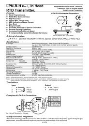
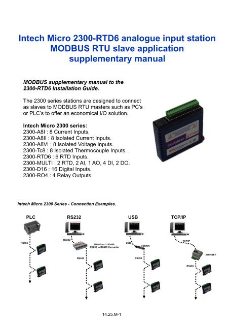
Intech Micro <strong>2300</strong>-<strong>RTD6</strong> analogue input station<strong>MODBUS</strong> RTU slave application<strong>supplementary</strong> <strong>manual</strong><strong>MODBUS</strong> <strong>supplementary</strong> <strong>manual</strong> to the<strong>2300</strong>-<strong>RTD6</strong> Installation Guide.The <strong>2300</strong> series stations are designed to connectas slaves to <strong>MODBUS</strong> RTU masters such as PC’sor PLC’s to offer an economical I/O solution.Intech Micro <strong>2300</strong> series:<strong>2300</strong>-A8I : 8 Current Inputs.<strong>2300</strong>-A8II : 8 Isolated Current Inputs.<strong>2300</strong>-A8VI : 8 Isolated Voltage Inputs.<strong>2300</strong>-Tc8 : 8 Isolated Thermocouple Inputs.<strong>2300</strong>-<strong>RTD6</strong> : 6 RTD Inputs.<strong>2300</strong>-MULTI : 2 RTD, 2 AI, 1 AO, 4 DI, 2 DO.<strong>2300</strong>-D16 : 16 Digital Inputs.<strong>2300</strong>-RO4 : 4 Relay Outputs.Intech Micro <strong>2300</strong> Series - Connection Examples.PLCRS232USBTCP/IPRS485RS2322100-IS or 2100-NSRS232 to RS485 ConverterUSBUSB485TCP/IPRS485RS485<strong>2300</strong>-NETRS48514.25.M-1
<strong>2300</strong>-<strong>RTD6</strong> Specifications.RTD Inputs: -Input Points 6-RTD Configuration2 or 3 Wire-Resolution0.1°C-Drift100ppm/°C Typ.-Line resistance effect < 0.1°C balanced-Max. Line resistance 100ohms-Isolation1500Vrms between field and logicRTD Type:-Number Type Range Accuracy-1 Pt100 -200 to 850°C ± 0.3°C,IEC 751:1983-2 Ni120 -80 to 320°C ± 0.3°C-3 Pt1000 -200 to 850°C ± 0.3°C-4 Ni1000-DIN -200 to 850°C ± 0.3°C-5 Ni1000-Landys&Gyr -200 to 850°C ± 0.3°C-6 Ohms 10~400 ohms ± 0.05%-7 Ohms 100~4000 ohms ± 0.05%Connectors: -Logic Power and Comms 4 Pin plug-in connector on side of station-Inputs18 Way screw plug-in connector on top of stationComms: -Protocols RS485, Modbus RTU-Baud Rate 2400, 4800, 9600, 19200, 38400, 57600, 115200-FormatParity: 0 = none, 1 = even, 2 = oddStop Bits: 1 = 1 stop bit, 2 = 2 stop bitsPower Supply: -Logic Supply Voltage 12~24Vdc-Logic Supply Current 87mA @ 12V / 45mA @ 24VSafety and EMC Compliances:EMC Compliance 89/336/EEC and Low Voltage Equipment Directive 73/23/EECSafety Compliance IEC 950General Specifications: (Unless otherwise stated in other input specifications).Operating Temperature-10~50˚CStorage Temperature-40~85˚COperating HumidityUp to 95% non condensingHousing -Dimensions L=97.5, W=22.6, H=109mm-Mounting35mm Symmetrical Mounting Rail.Note 1. Contact INTECH INSTRUMENTS for more detailed programming information.Product Liability. This information describes our products. It does not constitute guaranteed properties and is not intended to affirm the suitabilityof a product for a particular application. Due to ongoing research and development, designs, specifications, and documentation are subject tochange without notification. Regrettably, omissions and exceptions cannot be completely ruled out. No liability will beaccepted for errors, omissions or amendments to this specification. Technical data are always specified by their average values and are based onStandard Calibration Units at 25C, unless otherwise specified. Each product is subject to the ‘Conditions of Sale’.Warning: These products are not designed for use in, and should not be used for patient connected applications. In any criticalinstallation an independent fail-safe back-up system must always be implemented.Modbus Register Types.There are 4 types of variables which can be accessed from the station. Each station has one or more of these datavariables.Type Start Address Variable Access1 00001 Digital Outputs Read & Write2 10001 Digital Inputs Read Only3 30001 Input registers (Analog) Read Only4 40001 Output registers (Analog) Read & Write (Holding type)Note: The Modbus message length must be limited to 100 consecutive read or write registers. If more registers arerequired then a new poll group must be added for the next xxx registers.14.25.M-2
The <strong>2300</strong>-<strong>RTD6</strong> station is a 6 RTD input station. The station can accommodate either 2 or 3 wire RTD sensors. TheRTD inputs are isolated from the logic.The RTD resistance is read by the station circuitry, linearised and converted to degrees Centigrade. No ranging isrequired as the station covers the full range of the RTD as indicated in the RTD table. The value that is read from theModbus register is the actual temperature in degrees centigrade to 0.1°C resolution. ie: a value of 3451 correspondsto a temperature of 345.1°C.The RTD type is setup by writing a value to the RTD Type register. The value is obtained from the table below. Forexample to select a Pt100 RTD, the value "1" must be written to the RTD Type register. All 6 RTD inputs adopt thesame RTD type.The DIP switch 9 is used to select upscale or downscale burnout for break detection. A value of 32768 is used toindicate upscale burnout and a value of -32767 is used to indicate downscale burnout.Note: As there is no inter-channel isolation, isolated RTD's must be used in order to prevent ground loops andreading errors.Communications Settings.The data in the stations is stored in 16 bit registers. These registers are accessed over the network using the<strong>MODBUS</strong> RTU communication protocol.Communications Settings with DIP Switch 10 OFF (Default)BAUD RATE 9600DATA BITS 8PARITY NONESTOP BITS 1Communications Settings with DIP Switch 10 ON (Programmed Baud Rate)BAUD RATE 2400, 4800, 9600, 19200, 38400, 57600, 115200DATA BITS 8PARITY None, Even, OddSTOP BITS 1, 2Note: To change these settings, download the free MicroScan IOStudio <strong>2300</strong> series <strong>MODBUS</strong> configuration softwarevia the link from the Intech website: www.intech.co.nz/<strong>2300</strong>During this mode, DIP Switch 10 should be OFF so that the PC can communicate with the <strong>2300</strong> station using thedefault communication settings. Once the Communications Settings are programmed, power down the <strong>2300</strong> stationand change DIP Switch 10 to the ON position. Restore the power to the <strong>2300</strong> station and the configuredCommunications Settings will be ready for use.Warning: Only program ONE <strong>2300</strong> station at a time!Communications Settings Registers.40121 Baud Rate 2400 11520 R/W 2400, 4800, 9600, 19200, 38400, 57600, 11520040122 Parity 0 2 R/W 0 = none, 1 = even, 2 = odd40123 Stop Bits 1 2 R/W 1 = 1 stop bit, 2 = 2 stop bits40124 Reply Delay 0 65535 R/W (x10ms)14.25.M-3
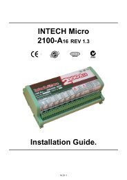
Baud Rate Register (40121)The baud rate value is programmed directly into the baud rate register. The only exception is the 115200 baud ratewhere the value 11520 is used.Parity Register (40122)The parity can be set to none by writing a 0 to the parity register, set to even by writing a 1 to the parity Register orset to odd by writing a 2 to the parity register.Stop Bits Register (40123)The number of stop bits can be set to 1 by writing a 1 to the stop bits register or set to 2 by writing a 2 to the stop bitsRegister.Reply Delay Register (40124)The reply delay is a time delay between the Modbus message received to the reply being sent. In some applicationswhere a modem or radio is used in the RS485 network, it may be necessary to add a reply delay due to turn arounddelays in the equipment.Reply DelayRx RequestTx ReplyTime (x10ms)Status Indicators.Power:RS485 Rx:RS485 Tx:Input Status:Flashes to indicate the CPU is running.Flashes to indicate the unit has received a valid Modbus message.Flashes to indicate the unit has sent a Modbus message.“ON” when the RTD is open circuit.“OFF” when the RTD is connected.PowerRS485 RxInput Status1 - 6RS485 TxSwitch 1 Switch 10<strong>2300</strong>-<strong>RTD6</strong>The following diagram shows the wiring for the power and RS485 communications.Pin81 182 271 370 4Connection- 12Vdc @ 87mA+ 24Vdc @ 45mA+ Comms- RS485Note: If power/communication connections are reversed, station may become faulty.14.25.M-4
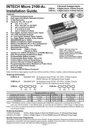
Wiring.The following diagram shows how the inputs are connected to a 2 and 3 wire RTD.+24Vdc+<strong>2300</strong>-<strong>RTD6</strong>Input 1CommonInput 2CommonInput 3CommonInput 4CommonInput 5CommonInput 6CommonInput 7CommonInput 8Common+V0V/Common+--Current Source0(4)-20mA+24Vdc+12-24Vdc0VdcTwo Wire Transmitter0(4)-20mASensorDip Switch Settings.1 STATION ID +1 Station ID’s from 0 to 127 are set up using switches 1 to 72 STATION ID +2 “3 STATION ID +4 “4 STATION ID +8 “5 STATION ID +16 “6 STATION ID +32 “7 STATION ID +64 “8 - Not used.9 BREAK RTD break. When switched off the RTD value will loaded with -32767 whenthe RTD is faulty. When switched on the RTD value will be loaded with 32768.10 BAUD RATE Selects 9600 (off) or Programmed Baud Rate (on)14.25.M-5
Data Registers.Modbus Register Name Low High AccessDescriptionAddressLimit Limit30001 S/W Version /Module TypeN/A N/A R High Byte = Software VersionLow Byte = 10930002 RTD Input 1 -xxx.x yyyy.y R RTD Inputs. See table for range.30003 RTD Input 2 -xxx.x yyyy.y R Resolution in 0.1°C.30004 RTD Input 3 -xxx.x yyyy.y R "30005 RTD Input 4 -xxx.x yyyy.y R "30006 RTD Input 5 -xxx.x yyyy.y R "30007 RTD Input 6 -xxx.x yyyy.y R "30008 Input Status 0 65535 R bit1 = 0(OK),bit1 = 1(error or open circuit)30100 DIP Switch 0 65535 R Status of DIP Switch on Front Panel40101 RTD Type 1 7 R/W See RTD Tables.40102 Line Frequency 50 60 R/W Line Frequency40103 Units Type 1 2 R/W 1=°C, 2=°F40121 Baud Rate 2400 11520 R/W 2400, 4800, 9600, 19200, 38400, 57600, 11520040122 Parity 0 2 R/W 0 = none, 1 = even, 2 = odd40123 Stop Bits 1 2 R/W 1 = 1 stop bit, 2 = 2 stop bits40124 Reply Delay 0 65535 R/W 0 = Disable, >0 = Enable. (x10ms)RTD Input Status.There is one status bits associated with each RTD input. These bits are used to indicate if the input is open circuitor over range. If the input is open circuit or over range, then the error bit will be set.Bit 1- Error Bit 2-Not Used Condition Status LED0 0 Input working OK (LED OFF)1 0 Open circuit / Over range (LED ON)The analog input status can be read in a single register as follows:MSB <strong>2300</strong>-<strong>RTD6</strong> ANALOG INPUT STATUS LSB15 14 13 12 11 10 9 8 7 6 5 4 3 2 1 0ADDRESS32768 16384 8192 4096 2048 1024 512 256 128 64 32 16 8 4 2 1 30008IP1 ErrorIP2 ErrorIP3 ErrorIP4 ErrorIP5 ErrorIP6 Error14.25.M-6www.intech.co.nzChristchurch Ph: +64 3 343 0646Auckland Ph: 09 827 1930Email: sales@intech.co.nz<strong>2300</strong>-<strong>RTD6</strong> <strong>MODBUS</strong> Supplement 281009