Soft starters - Trinet
Soft starters - Trinet
Soft starters - Trinet

Create successful ePaper yourself
Turn your PDF publications into a flip-book with our unique Google optimized e-Paper software.
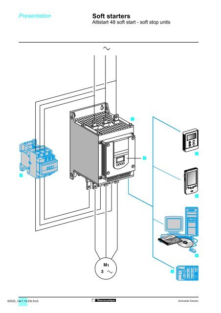
Presentation <strong>Soft</strong> <strong>starters</strong> 0<br />
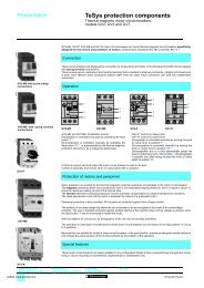
Altistart 48 soft start - soft stop units<br />
1<br />
2<br />
4<br />
3<br />
5<br />
6<br />
7<br />
60520_Ver1.10-EN.fm/2<br />
Schneider Electric
Presentation (continued) <strong>Soft</strong> <strong>starters</strong> 0<br />
Altistart 48 soft start - soft stop units<br />
Applications<br />
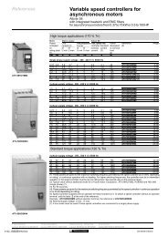
The Altistart 48 soft start - soft stop unit is a controller with 6 thyristors which is used<br />
for the torque-controlled soft starting and stopping of three-phase squirrel cage<br />
asynchronous motors in the power range between 4 and 1200 kW.<br />
It offers soft starting and deceleration functions along with machine and motor<br />
protection functions as well as functions for communicating with control systems.<br />
These functions are designed for use in state-of-the-art applications in centrifugal<br />
machines, pumps, fans, compressors and conveyors, which are primarily to be found<br />
in the construction, food and beverages and chemical industries. The highperformance<br />
algorithms of the Altistart 48 contribute significantly to its robustness,<br />
safety and ease of setup.<br />
The Altistart 48 soft start - soft stop unit is a cost-effective solution which can:<br />
# Reduce machine operating costs by reducing mechanical stress and improving<br />
machine availability<br />
# Reduce the stress placed on the electrical distribution system by reducing line<br />
current peaks and voltage drops during motor starts<br />
The Altistart soft start - soft stop unit offer comprises 2 ranges:<br />
# Three-phase voltages 230 to 415 V, 50/60 Hz<br />
# Three-phase voltages 208 to 690 V, 50/60 Hz<br />
In each voltage range, the Altistart soft start - soft stop units are dimensioned for<br />
standard and severe applications.<br />
Functions<br />
The Altistart 48 soft start - soft stop unit ( 1 ) is supplied ready for use in a standard<br />
application with motor protection class 10 (see page 60526/5).<br />
It comprises a built-in terminal ( 2 ) which can be used to modify programming,<br />
adjustment or monitoring functions in order to adapt and customise the application to<br />
meet individual customer requirements.<br />
# Drive performance functions:<br />
5 Exclusive Altistart torque control (patented by Schneider Electric)<br />
5 Constant control of the torque supplied to the motor during acceleration and<br />
deceleration periods (significantly reducing pressure surges)<br />
5 Facility for adjusting the ramp and the starting torque<br />
5 The starter can be bypassed using a contactor ( 3 ) at the end of the starting<br />
period whilst maintaining electronic protection (bypass function)<br />
5 Wide frequency tolerance for generator set power supplies<br />
5 The starter can be connected to the motor delta terminals in series with each<br />
winding<br />
# Machine and motor protection functions:<br />
5 Built-in motor thermal protection<br />
5 Processing of information from PTC thermal probes<br />
5 Monitoring of the starting time<br />
5 Motor preheating function<br />
5 Protection against underloads and overcurrents during continuous operation<br />
# Functions facilitating the integration of the unit into control systems:<br />
5 4 logic inputs, 2 logic outputs, 3 relay outputs and 1 analogue output<br />
5 Plug-in I/O connectors<br />
5 Function for configuring a second motor and easy-to-adapt settings<br />
5 Display of electrical values, the state of the load and the operating time<br />
5 RS 485 serial link for connection to Modbus<br />
Options<br />
A remote terminal ( 4 ) can be mounted on the door of a wall-fixing or floor-standing<br />
enclosure.<br />
PowerSuite advanced dialogue solutions:<br />
# PowerSuite Pocket PC with PPC type terminal ( 5 ),<br />
# PowerSuite software workshop ( 6 ).<br />
A range of wiring accessories for connecting the starter to PLCs via a Modbus<br />
connection ( 7 ).<br />
Bus communication and Ethernet, Fipio, DeviceNet and Profibus DP network<br />
communication options<br />
Characteristics:<br />
pages 60521/2 to 60521/5<br />
References:<br />
pages 60522/2 to 60522/5<br />
Dimensions:<br />
pages 60523/2 to 60523/5<br />
Schemes:<br />
pages 60524/2 to 60524/7<br />
Schneider Electric<br />
60520_Ver1.10-EN.fm/3
Characteristics <strong>Soft</strong> <strong>starters</strong> 0<br />
Altistart 48 soft start - soft stop units<br />
Environment<br />
Conformity to standards<br />
The electronic <strong>starters</strong> have been developed and<br />
performance tested in accordance with<br />
international standards, in particular with the<br />
&Ãmarking<br />
starter product standard EN/IEC 60947-4-2.<br />
Products have CE marking in accordance with the<br />
harmonised standard EN/IEC 60947-4-2.<br />
Product approvals<br />
UL, CSA<br />
Pending: DNV, C-Tick, Ghost, CCIB<br />
Degree of protection Starters ATS 48D17/ to 48C11/ IP 20 (IP 00 in the absence of connections)<br />
Starters ATS 48C14/ to 48M12/<br />
IP 00<br />
(1)<br />
Vibration resistance Conforming to IEC 60068-2-6 1.5 mm from 2 to 13 Hz<br />
1gn from 13 to 200 Hz<br />
Shock resistance Conforming to IEC 60068-2-27 15 g for 11 ms<br />
Starter noise level (2) Starters ATS 48D32/ to D47/ dBA 52<br />
Starters ATS 48D62/ to C11/ dBA 58<br />
Starters ATS 48C14/ to C17/ dBA 50<br />
Starters ATS 48C21/ to C32/ dBA 54<br />
Starters ATS 48C41/ to C66/ dBA 55<br />
Starters ATS 48C79/ to M12/ dBA 60<br />
Fans Starters ATS 48D17/ and D22/ Natural convection<br />
Starters ATS 48D32/ to M12/<br />
Forced convection. The fans are activated<br />
automatically when a temperature threshold is<br />
reached.<br />
For flow rate see page 60523/5.<br />
Ambient temperature around the unit Operation °C - 10...+ 40 without derating (between + 40 and +<br />
60, derate the nominal current of the Altistart by<br />
2% for each °C).<br />
Storage, conforming to<br />
°C - 25...+ 70<br />
IEC 60947-4-2<br />
Maximum relative humidity Conforming to IEC 60068-2-3 95% without condensation or dripping water<br />
Maximum ambient pollution Conforming to IEC 60664-1 Level 3<br />
Maximum operating altitude m 1000 without derating (above this, derate the<br />
nominal current of the Altistart by 2.2% for each<br />
additional 100 m). Limit to 2000 m.<br />
Operating position<br />
Maximum permanent angle in relation to the normal vertical<br />
mounting position<br />
Electrical characteristics<br />
Operating category Conforming to IEC 60947-4-2 AC-53a<br />
Three-phase supply voltage Starters ATS 48///Q V 230 -15% to 415 + 10%<br />
Starters ATS 48///Y V 208 - 15% to 690 + 10%<br />
Frequency Hz 50/60 ± 5% (automatic)<br />
50 or 60 ± 20% (must be set)<br />
Nominal starter current Starters ATS 48///Q A 17...1200<br />
Starters ATS 48///Y A 17 to 1200<br />
Motor power Starters ATS 48///Q kW 4 to 630<br />
Starters ATS 48///Y kW/HP 5.5 to 900/5 to 1200<br />
Voltage indicated on the motor rating plate Starters ATS 48///Q V 230 to 415<br />
Starters ATS 48///Y V 208 to 690<br />
Starter control circuit supply voltage Starters ATS 48///Q V 220 - 15% to 415 + 10%, 50/60 Hz<br />
Starters ATS 48///Y V 110 - 15% to 230 + 10%, 50/60 Hz<br />
Maximum control circuit consumption<br />
(with fans operating)<br />
Relay output (2 configurable outputs)<br />
Starters ATS 48D17/ to C17/ W 30<br />
Starters ATS 48C21/ to C32/ W 50<br />
Starters ATS 48C41/ to M12/ W 80<br />
3 relay outputs (R1, R2, R3), normally open contacts 1"N/O"<br />
Minimum switching capacity: 10 mA for $Ã6 V.<br />
Maximum switching capacity on inductive load: 1.8 A for " 230 V<br />
and $ 30 V (cos ϕ= 0.5 and L/R=20ms). Maximum nominal operating voltage " 400 V.<br />
Factory setting: R1 assigned as the "fault relay" (configurable)<br />
R2 assigned as the "end of starting relay" to control the starter bypass relay<br />
R3 assigned as "motor powered" (configurable)<br />
(1) Protective covers can be fitted to the power terminals of ATS 48C14/ to C32/ <strong>starters</strong>. ATS 48C41/ to 48M12/ <strong>starters</strong> have protection on the front panel and<br />
on the sides.<br />
(2) Starters located 1 m away. The noise levels may change depending on the characteristics of the fans.<br />
Presentation:<br />
pages 60520/2 and 60520/3<br />
References:<br />
pages 60522/2 to 60522/5<br />
Dimensions:<br />
pages 60523/2 to 60523/5<br />
Schemes:<br />
pages 60524/2 to 60524/7<br />
60521_Ver1.10-EN.fm/2<br />
Schneider Electric
Characteristics (continued) <strong>Soft</strong> <strong>starters</strong> 0<br />
Altistart 48 soft start - soft stop units<br />
Electrical characteristics (continued)<br />
Logic inputs LI (2 configurable inputs)<br />
4 logic inputs, impedance 4.3 kΩ, isolated: Stop, Run, LI3, LI4.<br />
+ 24 V power supply (maximum 30 V) I max. 8 mA<br />
State 0 if U < 5 V and I < 2 mA<br />
State 1 if U > 11 V and I > 5 mA<br />
Internal source available<br />
1 x + 24 V output, isolated and protected against short-circuits and overloads.<br />
Accuracy ± 25%. Max. current 200 mA.<br />
Logic outputs LO (configurable)<br />
2 logic outputs LO1 and LO2 with 0 V common, compatible with level 1 PLC, according<br />
to standard IEC 65A-68.<br />
+ 24 V power supply (minimum: +12 V, maximum: + 30 V).<br />
Maximum output current: 200 mA if supplied externally<br />
Analogue output AO (configurable)<br />
Current output 0-20 mA or 4-20 mA<br />
Maximum load impedance: 500 Ω<br />
Accuracy ± 5% of the maximum value<br />
Input for PTC probe Total resistance of probe circuit 750 Ω at 25°C, according to IEC 60 738-A<br />
Maximum I/O connection capacity 2.5 mm 2 (AWG 12)<br />
Communication<br />
RS 485 multidrop serial link integrated in the starter, for Modbus,<br />
with RJ45 type connector<br />
Transmission speed 4800, 9600 or 19200 bps<br />
Maximum number of Altistart 48 connected: 18<br />
Other uses:<br />
- connection to a remote terminal or<br />
- connection to a PC or<br />
- connection to other buses and networks via communication options.<br />
Protection Thermal Built-in, starter and motor (calculated and/or thermal protection with PTC probes)<br />
Line protection<br />
Phase failure, indicated by output relay<br />
Current settings<br />
The nominal motor current In can be adjusted from 0.4 to 1.3 times the starter nominal<br />
current.<br />
Adjustment of the maximum starting current from 1.5 to 7 times the motor In, limited to<br />
5 times the starter nominal current.<br />
Starting mode<br />
By torque control with starter current limited to 5 In maximum.<br />
Factory setting: 4 In for standard operation on 15 s torque ramp<br />
Stopping mode Freewheel stop "Freewheel" stop (factory setting)<br />
Controlled stop on torque ramp Programmed between 0.5 and 60 s (for pump applications)<br />
Braked stop<br />
Controlled dynamically by the flux<br />
Electromagnetic compatibility EMC (1)<br />
Standards Test levels Examples<br />
(sources of interference)<br />
Summary of immunity tests carried out with the Altistart 48 IEC 61000-4-2 level 3<br />
Electrostatic discharge:<br />
- by contact<br />
- in the air<br />
IEC 61000-4-3 level 3<br />
Radiated electromagnetic fields<br />
IEC 61000-4-4 level 4<br />
Rapid electrical transients:<br />
- power supply cables<br />
- control cables<br />
IEC 61000-4-5 level 3<br />
Shock wave:<br />
- phase/phase<br />
- phase/earth<br />
IEC 61000-4-12 level 3<br />
Damped oscillating waves<br />
6 kV<br />
8 kV<br />
Contact off an electrically charged<br />
individual<br />
10 V/m Equipment transmitting radio<br />
frequencies<br />
4 kV<br />
2 kV<br />
1 kV<br />
2 kV<br />
Opening/closing of a contactor<br />
Oscillating circuit on the line supply<br />
1 kV - 1 M Hz<br />
Radiated and conducted emissions<br />
According to IEC 60947-4-2, class A, on all <strong>starters</strong><br />
According to IEC 60947-4-2, class B, on <strong>starters</strong> up to 170 A: ATS 48D17/ to 48C17/.<br />
Must be bypassed at the end of starting<br />
(1) The <strong>starters</strong> conform to product standard IEC 60947-4-2, in particular with regard to EMC. This standard ensures a level of immunity for products and a level of<br />
emitted interference. In steady state, the interference emitted is below that required by the standard. During acceleration and deceleration phases, low level<br />
loads may be affected by low frequency interference (harmonics). To reduce this interference, connect chokes between the line supply and the Altistart 48 (see<br />
page 60528/3).<br />
Note:<br />
# Power factor correction capacitors can only be used upstream of the Altistart and only powered up at the end of starting.<br />
# The starter must be earthed to conform to the regulations concerning leakage currents (6 30 mA). When the use of an upstream "residual<br />
current device" for protection is required by the installation standards, an A-Si type device must be used. Check its compatibility with the other<br />
protective devices. If the installation involves several <strong>starters</strong> on the same line supply, each starter must be earthed separately.<br />
-<br />
Presentation:<br />
pages 60520/2 and 60520/3<br />
References:<br />
pages 60522/2 to 60522/5<br />
Dimensions:<br />
pages 60523/2 to 60523/5<br />
Schemes:<br />
pages 60524/2 to 60524/7<br />
Schneider Electric<br />
60521_Ver1.10-EN.fm/3
Characteristics (continued) <strong>Soft</strong> <strong>starters</strong> 0<br />
Altistart 48 soft start - soft stop units<br />
Torque characteristics<br />
Curves indicating changes in the torque depending on the starting current of a threephase<br />
asynchronous motor.<br />
Curves 1: direct line starting<br />
Curves 2: starting in current limiting mode<br />
Torque curve Ts1 indicates the total torque range available depending on the limiting<br />
current Is1.<br />
Limiting the starting current Is to a preset value Is1 will reduce the starting torque Ts1<br />
to a value which is almost equal to the square of currents Is1/Is.<br />
Example:<br />
For motor characteristics: Ts = 3 Tn for Is = 6 In,<br />
limit the current to Is1 = 3 In (0.5 Is)<br />
resulting in a starting torque Ts1 = Ts x (0.5)² = 3 Tn x 0.25 = 0.75 Tn<br />
Starting current<br />
1 Direct line starting current<br />
2 Starting current limited to Is1<br />
I/In<br />
6<br />
5<br />
1<br />
4<br />
3<br />
Id1<br />
2<br />
2<br />
1<br />
0<br />
0 0,25 0,5 0,75<br />
1<br />
N/Ns<br />
Starting torque<br />
1 Direct line starting torque<br />
2 Starting torque with current limited<br />
to Is1<br />
C/Cn<br />
6<br />
5<br />
4<br />
3<br />
1<br />
2<br />
2<br />
Cd1<br />
Cr<br />
1<br />
0<br />
0 0,25 0,5 0,75<br />
1<br />
N/Ns<br />
Presentation:<br />
pages 60520/2 and 60520/3<br />
References:<br />
pages 60522/2 to 60522/5<br />
Dimensions:<br />
pages 60523/2 to 60523/5<br />
Schemes:<br />
pages 60524/2 to 60524/7<br />
60521_Ver1.10-EN.fm/4<br />
Schneider Electric
Characteristics (continued) <strong>Soft</strong> <strong>starters</strong> 0<br />
Altistart 48 soft start - soft stop units<br />
Conventional starting using current limitation or voltage ramp<br />
With current limitation Is1, the accelerating torque applied to the motor is equal to the<br />
motor torque Ts1 minus the resistive torque Tr.<br />
The accelerating torque increases in the starting range as the speed changes and is<br />
at its highest at the end of acceleration (curve 2).<br />
This characteristic means that the load is taken up very abruptly, which is not<br />
recommended for pump type applications.<br />
Example of speed curve for starting with current<br />
limitation<br />
1 Current applied to the motor (I/In)<br />
2 Motor speed N/Ns<br />
I/In<br />
4<br />
N/Ns<br />
1<br />
3<br />
1<br />
2 0,5<br />
2<br />
1<br />
Starting with the Altistart 48<br />
Example of speed curve for starting with torque control<br />
1 Current applied to the motor (I/In)<br />
2 Motor speed N/Ns<br />
0<br />
Torque control on the Altistart 48 applies the torque to the motor during the entire<br />
starting phase if the current required (curve 1) does not exceed the limiting current.<br />
The accelerating torque can be virtually constant over the entire speed range<br />
(curve 2).<br />
It is possible to set the Altistart in order to obtain a high torque on starting for a rapid<br />
motor speed rise whilst limiting its temperature rise, and a lower accelerating torque<br />
at the end of starting for gradual loading.<br />
This control function is ideal for centrifugal pumps or for machines with high resistive<br />
torque on starting.<br />
I/In<br />
N/Ns<br />
4 1<br />
t<br />
3<br />
1<br />
2 0,5<br />
2<br />
1<br />
Stopping with the Altistart 48<br />
0<br />
# Freewheel stop: the motor comes to a freewheel stop.<br />
# Decelerated stop: this type of stop is ideal for pumps and can be used to effectively<br />
reduce pressure surges. Torque control on the Altistart 48 reduces the effect of<br />
hydraulic transients even if the load increases. This type of control makes adjustment<br />
easy.<br />
# Braked stop: this type of stop is suitable for high inertia applications as it reduces<br />
the stopping time of the machine.<br />
t<br />
Presentation:<br />
pages 60520/2 and 60520/3<br />
References:<br />
pages 60522/2 to 60522/5<br />
Dimensions:<br />
pages 60523/2 to 60523/5<br />
Schemes:<br />
pages 60524/2 to 60524/7<br />
Schneider Electric<br />
60521_Ver1.10-EN.fm/5
Selection criteria <strong>Soft</strong> <strong>starters</strong> 0<br />
Altistart 48 soft start - soft stop units<br />
Selection criteria for an Altistart 48 soft start - soft stop unit<br />
The Altistart 48 must be selected on the basis of 3 main criteria:<br />
# Two line power supply voltage ranges are available for selection:<br />
5 Three-phase a.c. voltage: 230 - 415 V<br />
5 Three-phase a.c. voltage: 208 - 690 V<br />
# The power and the nominal current indicated on the motor name plate<br />
# The type of application and the operating cycle:<br />
To simplify selection, the applications are categorised into 2 types:<br />
5 Standard applications<br />
5 Severe applications<br />
Standard or severe applications define the limiting values of the current and the cycle<br />
for motor duties S1 and S4.<br />
Standard application<br />
In standard applications, the Altistart 48 is designed to provide:<br />
# Starting at 4 In for 23 seconds or at 3 In for 46 seconds from a cold state<br />
(corresponding to motor duty S1)<br />
# Starting at 3 In for 23 seconds or at 4 In for 12 seconds<br />
with a load factor of 50% and 10 starts per hour or a an equivalent thermal cycle<br />
(corresponding to motor duty S4)<br />
The motor thermal protection must conform to protection class 10<br />
(see page 60526/4).<br />
Example: centrifugal pump<br />
Severe application<br />
In severe applications, the Altistart 48 is designed to provide:<br />
# Starting at 4 In for 48 seconds or at 3 In for 90 seconds from a cold state<br />
(corresponding to S1 motor duty)<br />
# Starting at 4 In for 25 seconds with a load factor of 50% and 5 starts per hour or a<br />
an equivalent thermal cycle (corresponding to S4 motor duty)<br />
The motor thermal protection must conform to protection class 20<br />
(see page 60526/4).<br />
Example: grinder<br />
Motor duties<br />
S1 motor duty corresponds to starting followed by operation at constant load<br />
enabling the thermal equilibrium to be reached.<br />
S4 motor duty corresponds to a cycle comprising starting,<br />
operation at constant load and an idle period.<br />
This cycle is characterised by a load factor of 50%.<br />
Selecting the starter<br />
Once the appropriate application has been selected from the following page, select<br />
the starter from pages 60522/2 to 60522/5 according to the supply voltage<br />
and the motor power.<br />
Caution:<br />
If the Altistart 48 is installed inside an enclosure, observe the mounting and derating<br />
recommendations (see page 60523/5).<br />
60529_Ver1.10-EN.fm/2<br />
Schneider Electric
Selection criteria (continued) <strong>Soft</strong> <strong>starters</strong> 0<br />
Altistart 48 soft start - soft stop units<br />
Application areas<br />
Depending on the type of machine, the applications are categorized as standard or severe based on the starting characteristics, which are<br />
given as examples only, in the table below.<br />
Type of machine Application Functions performed by the Altistart 48 Starting current<br />
(% In)<br />
Centrifugal pump Standard Deceleration (reduction in pressure surges)<br />
Protection against underloads or inversion<br />
of the phase rotation direction<br />
300 5 to 15<br />
Starting time<br />
(s)<br />
Piston pump Standard Control of running dry and direction of rotation<br />
of the pump<br />
350 5 to 10<br />
Fan<br />
Standard<br />
Severe if > 30 s<br />
Detection of overloads caused by clogging<br />
or underloads (motor fan<br />
transmission broken)<br />
Braking torque on stopping<br />
300 10 to 40<br />
Cold compressor Standard Protection, even for special motors 300 5 to 10<br />
Screw compressor Standard Protection against inversion of direction of<br />
phase rotation<br />
Contact for automatic draining on stopping<br />
300 3 to 20<br />
Centrifugal compressor<br />
Standard<br />
Severe if > 30 s<br />
Protection against inversion of direction of<br />
phase rotation<br />
Contact for automatic emptying on stopping<br />
350 10 to 40<br />
Piston compressor Standard Protection against inversion of direction of<br />
phase rotation<br />
Contact for automatic emptying on stopping<br />
Conveyor, transporter Standard Overload control for detecting faults<br />
or underload control for detecting breaks<br />
Lifting screw Standard Overload control for detecting hard spots<br />
or underload control for detecting breaks<br />
Drag lift Standard Overload control for detecting jamming<br />
or underload control for detecting breaks<br />
Lift Standard Overload control for detecting jamming<br />
or underload control for detecting breaks<br />
Constant starting with variable load<br />
350 5 to 10<br />
300 3 to 10<br />
300 3 to 10<br />
400 2 to 10<br />
350 5 to 10<br />
Circular saw, band saw<br />
Standard<br />
Severe if > 30 s<br />
Braking for fast stop 300 10 to 60<br />
Pulper, butchery knife Severe Torque control on starting 400 3 to 10<br />
Agitator Standard The current display indicates the density<br />
of the product<br />
Mixer Standard The current display indicates the density<br />
of the product<br />
Grinder Severe Braking to limit vibrations during stopping, overload<br />
control to detect jamming<br />
Crusher Severe Braking to limit vibrations during stopping, overload<br />
control to detect jamming<br />
350 5 to 20<br />
350 5 to 10<br />
450 5 to 60<br />
400 10 to 40<br />
Refiner Standard Torque control on starting and stopping 300 5 to 30<br />
Press Severe Braking to increase the number of cycles 400 20 to 60<br />
Schneider Electric<br />
60529_Ver1.10-EN.fm/3
Selection criteria (continued) <strong>Soft</strong> <strong>starters</strong> 0<br />
Altistart 48 soft start - soft stop units<br />
Special uses<br />
Other criteria can influence the selection of the Altistart 48:<br />
Starter wired to the motor delta terminal<br />
(see the recommended application diagram on page 60524/4)<br />
In addition to the most frequently encountered wiring layouts, where the starter is<br />
installed in the line supply of the motor and the motor is connected in star or delta<br />
configuration, the Altistart 48 ATS48•••Q can be wired to the motor delta terminal in<br />
series with each winding (see the application diagram below). The starter current is<br />
lower than the line current absorbed by the motor by a ratio of Æ. This type of<br />
installation enables a starter with a lower rating to be used.<br />
Example: For a 400 V/110 kW motor with a line current of 195 A (nominal current for<br />
the delta connection), the current in each winding is equal to 195/Æ, i.e. 114 A.<br />
Select the starter rating with a maximum permanent nominal current just above this<br />
current, i.e. 140A (ATS48C14Q for a standard application).<br />
To avoid making this calculation, simply use the table on page 60522/3.<br />
This type of installation only permits freewheel stopping and is not compatible with<br />
the cascade and preheating functions.<br />
ATS48•••Q<br />
motor<br />
Starter wired in series with the motor<br />
windings<br />
Note: The nominal current and limiting current settings as well as the current<br />
displayed during operation are on-line values (so do not have to be calculated by the<br />
user).<br />
Caution: For this type of installation, observe the wiring scheme and the associated<br />
recommendations on page 60524/4.<br />
Starter bypassed by a contactor<br />
(see the recommended application diagram on page 60524/3)<br />
The starter can be bypassed by a contactor at the end of starting (to limit the heat<br />
dissipated by the starter). The bypass contactor is controlled by the starter and the<br />
current measurements and protective mechanisms remain active when the starter is<br />
bypassed.<br />
The starter is selected on the basis of the 3 main criteria and one of the following<br />
criteria:<br />
# If the starter is bypassed at the end of starting, the motor is always started from<br />
cold state and the starter can be oversized by one rating.<br />
Example: Select an ATS 48D17Q for an 11 kW motor in a standard 400 V application.<br />
# If the starter must be able to operate without the bypass contactor at the end of<br />
starting, it does not have to be derated.<br />
Example: Select an ATS 48D17Q for a 7.5 kW motor in a standard 400 V application.<br />
60529_Ver1.10-EN.fm/4<br />
Schneider Electric
Selection criteria (continued) <strong>Soft</strong> <strong>starters</strong> 0<br />
Altistart 48 soft start - soft stop units<br />
Special uses (continued)<br />
Motors in parallel<br />
Motors may be connected in parallel provided that the power limit of the starter is not<br />
exceeded (the sum of the motor currents must not exceed the nominal current of the<br />
starter selected depending on the type of application). Provide thermal protection for<br />
each motor.<br />
Brush motor<br />
The Altistart 48 can operate with a bypassed stator resistance motor or with a<br />
resistance lug. The starting torque is modified in accordance with the rotor<br />
resistance. If necessary, maintain a low resistance in order to obtain the required<br />
torque to overcome the resistive torque on starting.<br />
A bypassed brush motor has a very low starting torque. A high stator current is<br />
required to obtain the sufficient starting torque.<br />
Oversize the starter in order that the value of the limiting current is 7 times that of the<br />
nominal current.<br />
Note: Ensure that the starting torque of the motor, equal to 7 times the nominal<br />
current, is greater than the resistive torque.<br />
Note: The Altistart 48 torque control enables excellent soft starting despite the<br />
limiting current being 7 times the nominal current required to start the motor.<br />
Dahlander motor and 2-speed motor<br />
The Altistart 48 can operate with a 2-speed motor. A motor demagnetisation period<br />
must elapse before changing from low speed to high speed in order to avoid<br />
antiphases between the line supply and the motor, which would generate very high<br />
currents.<br />
Select the starter using the 3 main criteria.<br />
Very long cable<br />
Very long motor cables cause voltage drops due to the resistance of the cable. If the<br />
voltage drop is significant, it could affect the current consumption and the torque<br />
available. This must therefore be taken into account when selecting the motor and<br />
the starter.<br />
Starters in parallel on the same line supply<br />
If several <strong>starters</strong> are installed on the same line supply, line chokes should be<br />
installed between the transformer and the starter (see page 60528/3).<br />
Recommendations for use<br />
Caution: Do not use the Altistart 48 upstream of loads other than motors (for<br />
example transformers and resistors are forbidden).<br />
Do not connect power factor correction capacitors to the terminals of a motor<br />
controlled by an Altistart 48.<br />
Schneider Electric<br />
60529_Ver1.10-EN.fm/5
References <strong>Soft</strong> <strong>starters</strong> 0<br />
Altistart 48 soft start - soft stop units<br />
Line voltage 230/415 V<br />
Connection in the motor supply line<br />
106762<br />
106761<br />
ATS 48D17Q<br />
For standard applications<br />
Motor<br />
Starter 230/415 V - 50/60 Hz<br />
Motor power<br />
(1)<br />
Nominal<br />
current<br />
(IcL)<br />
(2)<br />
Factory<br />
setting<br />
current<br />
(4)<br />
Power<br />
dissipated<br />
at nominal<br />
load<br />
Reference<br />
Weight<br />
230 V 400 V<br />
kW kW A A W kg<br />
4 7.5 17 14.8 59 ATS 48D17Q 4.900<br />
5.5 11 22 21 74 ATS 48D22Q 4.900<br />
7.5 15 32 28.5 104 ATS 48D32Q 4.900<br />
9 18.5 38 35 116 ATS 48D38Q 4.900<br />
11 22 47 42 142 ATS 48D47Q 4.900<br />
15 30 62 57 201 ATS 48D62Q 8.300<br />
18.5 37 75 69 245 ATS 48D75Q 8.300<br />
22 45 88 81 290 ATS 48D88Q 8.300<br />
30 55 110 100 322 ATS 48C11Q 8.300<br />
37 75 140 131 391 ATS 48C14Q 12.400<br />
45 90 170 162 479 ATS 48C17Q 12.400<br />
55 110 210 195 580 ATS 48C21Q 18.200<br />
75 132 250 233 695 ATS 48C25Q 18.200<br />
90 160 320 285 902 ATS 48C32Q 18.200<br />
110 220 410 388 1339 ATS 48C41Q 51.400<br />
132 250 480 437 1386 ATS 48C48Q 51.400<br />
160 315 590 560 1731 ATS 48C59Q 51.400<br />
– 355 660 605 1958 ATS 48C66Q 51.400<br />
220 400 790 675 2537 ATS 48C79Q 115.000<br />
250 500 1000 855 2865 ATS 48M10Q 115.000<br />
355 630 1200 1045 3497 ATS 48M12Q 115.000<br />
106758<br />
ATS 48C14Q<br />
ATS 48M12Q<br />
For severe applications<br />
Motor<br />
Starter 230/415 V - 50/60 Hz<br />
Motor power Nominal<br />
(1)<br />
current<br />
(3)<br />
Factory<br />
setting<br />
current<br />
(4)<br />
Power<br />
dissipated<br />
at nominal<br />
load<br />
Reference<br />
Weight<br />
230 V 400 V<br />
kW kW A A W kg<br />
3 5.5 12 14.8 46 ATS 48D17Q 4.900<br />
4 7.5 17 21 59 ATS 48D22Q 4.900<br />
5.5 11 22 28.5 74 ATS 48D32Q 4.900<br />
7.5 15 32 35 99 ATS 48D38Q 4.900<br />
9 18.5 38 42 116 ATS 48D47Q 4.900<br />
11 22 47 57 153 ATS 48D62Q 8.300<br />
15 30 62 69 201 ATS 48D75Q 8.300<br />
18.5 37 75 81 245 ATS 48D88Q 8.300<br />
22 45 88 100 252 ATS 48C11Q 8.300<br />
30 55 110 131 306 ATS 48C14Q 12.400<br />
37 75 140 162 391 ATS 48C17Q 12.400<br />
45 90 170 195 468 ATS 48C21Q 18.200<br />
55 110 210 233 580 ATS 48C25Q 18.200<br />
75 132 250 285 695 ATS 48C32Q 18.200<br />
90 160 320 388 1017 ATS 48C41Q 51.400<br />
110 220 410 437 1172 ATS 48C48Q 51.400<br />
132 250 480 560 1386 ATS 48C59Q 51.400<br />
160 315 590 605 1731 ATS 48C66Q 51.400<br />
– 355 660 675 2073 ATS 48C79Q 115.000<br />
220 400 790 855 2225 ATS 48M10Q 115.000<br />
250 500 1000 1045 2865 ATS 48M12Q 115.000<br />
(1) Value indicated on the motor rating plate<br />
(2) Corresponds to the maximum permanent current in class 10. IcL corresponds to the starter<br />
rating.<br />
(3) Corresponds to the maximum permanent current in class 20.<br />
(4) The factory setting current corresponds to the value of the nominal current of a standard<br />
4-pole, 400 V, class 10 motor (standard application). Adjust the settings in accordance with<br />
the motor nominal current.<br />
Presentation:<br />
pages 60520/2 and 60520/3<br />
Characteristics:<br />
pages 60521/2 to 60521/5<br />
Dimensions:<br />
pages 60523/2 and 60523/3<br />
Schemes:<br />
pages 60524/2 to 60524/7<br />
60522_Ver1.10-EN.fm/2<br />
Schneider Electric
References (continued) <strong>Soft</strong> <strong>starters</strong> 0<br />
Altistart 48 soft start - soft stop units<br />
Line voltage 230/415 V<br />
Connection to the motor delta terminals<br />
ATS 48///Q<br />
motor<br />
Figure 1<br />
Special use:<br />
Starter connected to the motor delta<br />
terminal in series with each winding<br />
For standard applications according to Figure 1<br />
Motor<br />
Starter 230/415 V - 50/60 Hz<br />
Motor power<br />
(1)<br />
Nominal<br />
current<br />
(2)<br />
Reference<br />
Factory<br />
setting<br />
current<br />
(4)<br />
Power<br />
dissipated<br />
at nominal<br />
load<br />
Weight<br />
230 V 400 V<br />
kW kW A A W kg<br />
7.5 15 29 14.8 59 ATS 48D17Q 4.900<br />
9 18.5 38 21 74 ATS 48D22Q 4.900<br />
15 22 55 28.5 104 ATS 48D32Q 4.900<br />
18.5 30 66 35 116 ATS 48D38Q 4.900<br />
22 45 81 42 142 ATS 48D47Q 4.900<br />
30 55 107 57 201 ATS 48D62Q 8.300<br />
37 55 130 69 245 ATS 48D75Q 8.300<br />
45 75 152 81 290 ATS 48D88Q 8.300<br />
55 90 191 100 322 ATS 48C11Q 8.300<br />
75 110 242 131 391 ATS 48C14Q 12.400<br />
90 132 294 162 479 ATS 48C17Q 12.400<br />
110 160 364 195 580 ATS 48C21Q 18.200<br />
132 220 433 233 695 ATS 48C25Q 18.200<br />
160 250 554 285 902 ATS 48C32Q 18.200<br />
220 315 710 388 1339 ATS 48C41Q 51.400<br />
250 355 831 437 1386 ATS 48C48Q 51.400<br />
– 400 1022 560 1731 ATS 48C59Q 51.400<br />
315 500 1143 605 1958 ATS 48C66Q 51.400<br />
355 630 1368 675 2537 ATS 48C79Q 115.000<br />
– 710 1732 855 2865 ATS 48M10Q 115.000<br />
500 – 2078 1045 3497 ATS 48M12Q 115.000<br />
For severe applications according to Figure 1<br />
Motor<br />
Starter 230/415 V - 50/60 Hz<br />
Motor power<br />
(1)<br />
Nominal<br />
current<br />
(3)<br />
Reference<br />
Factory<br />
setting<br />
current<br />
(4)<br />
Power<br />
dissipated<br />
at nominal<br />
load<br />
Weight<br />
230 V 400 V<br />
kW kW A A W kg<br />
5.5 11 22 14.8 46 ATS 48D17Q 4.900<br />
7.5 15 29 21 59 ATS 48D22Q 4.900<br />
9 18.5 38 28.5 74 ATS 48D32Q 4.900<br />
15 22 55 35 99 ATS 48D38Q 4.900<br />
18.5 30 66 42 116 ATS 48D47Q 4.900<br />
22 45 81 57 153 ATS 48D62Q 8.300<br />
30 55 107 69 201 ATS 48D75Q 8.300<br />
37 55 130 81 245 ATS 48D88Q 8.300<br />
45 75 152 100 252 ATS 48C11Q 8.300<br />
55 90 191 131 306 ATS 48C14Q 12.400<br />
75 110 242 162 391 ATS 48C17Q 12.400<br />
90 132 294 195 468 ATS 48C21Q 18.200<br />
110 160 364 233 580 ATS 48C25Q 18.200<br />
132 220 433 285 695 ATS 48C32Q 18.200<br />
160 250 554 388 1017 ATS 48C41Q 51.400<br />
220 315 710 437 1172 ATS 48C48Q 51.400<br />
250 355 831 560 1386 ATS 48C59Q 51.400<br />
– 400 1022 605 1731 ATS 48C66Q 51.400<br />
315 500 1143 675 2073 ATS 48C79Q 115.000<br />
355 630 1368 855 2225 ATS 48M10Q 115.000<br />
– 710 1732 1045 2865 ATS 48M12Q 115.000<br />
(1) Value indicated on the motor rating plate<br />
(2) Corresponds to the maximum permanent current in class 10.<br />
(3) Corresponds to the maximum permanent current in class 20.<br />
(4) For this type of connection. the factory setting current must be adjusted in accordance with<br />
the nominal motor current.<br />
Schneider Electric<br />
60522_Ver1.10-EN.fm/3
References (continued) <strong>Soft</strong> <strong>starters</strong> 0<br />
Altistart 48 soft start - soft stop units<br />
Line voltage 208/690 V<br />
Motor power in HP<br />
106762<br />
106761<br />
106758<br />
ATS 48D17Y<br />
ATS 48C14Y<br />
ATS 48M12Y<br />
For standard applications<br />
Motor<br />
Starter 208/690 V - 50/60 Hz<br />
Motor power (1)<br />
Nomina<br />
l<br />
Factory<br />
setting<br />
Power<br />
dissipated<br />
Reference Weigh<br />
t<br />
208 V 230 V 460 V 575 V<br />
current<br />
(IcL)<br />
(2)<br />
current(<br />
4)<br />
at nominal<br />
load<br />
HP HP HP HP A A W kg<br />
5 5 10 15 17 14 59 ATS 48D17Y 4.900<br />
7.5 7.5 15 20 22 21 74 ATS 48D22Y 4.900<br />
10 10 20 25 32 27 104 ATS 48D32Y 4.900<br />
– – 25 30 38 34 116 ATS 48D38Y 4.900<br />
15 15 30 40 47 40 142 ATS 48D47Y 4.900<br />
20 20 40 50 62 52 201 ATS 48D62Y 8.300<br />
25 25 50 60 75 65 245 ATS 48D75Y 8.300<br />
30 30 60 75 88 77 290 ATS 48D88Y 8.300<br />
40 40 75 100 110 96 322 ATS 48C11Y 8.300<br />
50 50 100 125 140 124 391 ATS 48C14Y 12.400<br />
60 60 125 150 170 156 479 ATS 48C17Y 12.400<br />
75 75 150 200 210 180 580 ATS 48C21Y 18.200<br />
– 100 200 250 250 240 695 ATS 48C25Y 18.200<br />
125 125 250 300 320 302 902 ATS 48C32Y 18.200<br />
150 150 300 350 410 361 1339 ATS 48C41Y 51.400<br />
– – 350 400 480 414 1386 ATS 48C48Y 51.400<br />
200 200 400 500 590 477 1731 ATS 48C59Y 51.400<br />
250 250 500 600 660 590 1958 ATS 48C66Y 51.400<br />
300 300 600 800 790 720 2537 ATS 48C79Y 115.000<br />
350 350 800 1000 1000 954 2865 ATS 48M10Y 115.000<br />
450 450 1000 1200 1200 1170 3497 ATS 48M12Y 115.000<br />
For severe applications<br />
Motor<br />
Starter 208/690 V - 50/60 Hz<br />
Motor power (1)<br />
Nominal<br />
current<br />
(3)<br />
Factory<br />
setting<br />
current<br />
(4)<br />
Power<br />
dissipated<br />
at nominal<br />
load<br />
Reference<br />
Weight<br />
208 V 230 V 460 V 575 V<br />
HP HP HP HP A A W kg<br />
3 3 7.5 10 12 14 46 ATS 48D17Y 4.900<br />
5 5 10 15 17 21 59 ATS 48D22Y 4.900<br />
7.5 7.5 15 20 22 27 74 ATS 48D32Y 4.900<br />
10 10 20 25 32 34 99 ATS 48D38Y 4.900<br />
– – 25 30 38 40 116 ATS 48D47Y 4.900<br />
15 15 30 40 47 52 153 ATS 48D62Y 8.300<br />
20 20 40 50 62 65 201 ATS 48D75Y 8.300<br />
25 25 50 60 75 77 245 ATS 48D88Y 8.300<br />
30 30 60 75 88 96 252 ATS 48C11Y 8.300<br />
40 40 75 100 110 124 306 ATS 48C14Y 12.400<br />
50 50 100 125 140 156 391 ATS 48C17Y 12.400<br />
60 60 125 150 170 180 468 ATS 48C21Y 18.200<br />
75 75 150 200 210 240 580 ATS 48C25Y 18.200<br />
– 100 200 250 250 302 695 ATS 48C32Y 18.200<br />
125 125 250 300 320 361 1017 ATS 48C41Y 51.400<br />
150 150 300 350 410 414 1172 ATS 48C48Y 51.400<br />
– – 350 400 480 477 1386 ATS 48C59Y 51.400<br />
200 200 400 500 590 590 1731 ATS 48C66Y 51.400<br />
250 250 500 600 660 720 2073 ATS 48C79Y 115.000<br />
300 300 600 800 790 954 2225 ATS 48M10Y 115.000<br />
350 350 800 1000 1000 1170 2865 ATS 48M12Y 115.000<br />
(1) Value indicated on the motor rating plate<br />
(2) Corresponds to the maximum permanent current in class 10. IcL corresponds to the starter<br />
rating.<br />
(3) Corresponds to the maximum permanent current in class 20.<br />
(4) The factory setting current corresponds to the value of the nominal current of a standard motor<br />
according to NEC, 460 V, class 10 (standard application). Adjust the settings in accordance<br />
with the motor nominal current.<br />
Presentation:<br />
pages 60520/2 and 60520/3<br />
Characteristics:<br />
pages 60521/2 to 60521/5<br />
Dimensions:<br />
pages 60523/2 and 60523/3<br />
Schemes:<br />
pages 60524/2 to 60524/7<br />
60522_Ver1.10-EN.fm/4<br />
Schneider Electric
References (continued) <strong>Soft</strong> <strong>starters</strong> 0<br />
Altistart 48 soft start - soft stop units<br />
Line voltage 208/690 V<br />
Motor power in kW<br />
For standard applications<br />
Motor<br />
Motor power (1)<br />
Starter 208/690 V - 50/60 Hz<br />
Nominal Factory<br />
current setting<br />
(IcL) current<br />
(2)<br />
(4)<br />
Power Reference<br />
dissipated at<br />
nominal load<br />
Weight<br />
230 V 400 V 440 V 500 V 525 V 660 V 690 V<br />
kW kW kW kW kW kW kW A A W kg<br />
4 7.5 7.5 9 9 11 15 17 14 59 ATS 48D17Y 4.900<br />
5.5 11 11 11 11 15 18.5 22 21 74 ATS 48D22Y 4.900<br />
7.5 15 15 18.5 18.5 22 22 32 27 104 ATS 48D32Y 4.900<br />
9 18.5 18.5 22 22 30 30 38 34 116 ATS 48D38Y 4.900<br />
11 22 22 30 30 37 37 47 40 142 ATS 48D47Y 4.900<br />
15 30 30 37 37 45 45 62 52 201 ATS 48D62Y 8.300<br />
18.5 37 37 45 45 55 55 75 65 245 ATS 48D75Y 8.300<br />
22 45 45 55 55 75 75 88 77 290 ATS 48D88Y 8.300<br />
30 55 55 75 75 90 90 110 96 322 ATS 48C11Y 8.300<br />
37 75 75 90 90 110 110 140 124 391 ATS 48C14Y 12.400<br />
45 90 90 110 110 132 160 170 156 479 ATS 48C17Y 12.400<br />
55 110 110 132 132 160 200 210 180 580 ATS 48C21Y 18.200<br />
75 132 132 160 160 220 250 250 240 695 ATS 48C25Y 18.200<br />
90 160 160 220 220 250 315 320 302 902 ATS 48C32Y 18.200<br />
110 220 220 250 250 355 400 410 361 1339 ATS 48C41Y 51.400<br />
132 250 250 315 315 400 500 480 414 1386 ATS 48C48Y 51.400<br />
160 315 355 400 400 560 560 590 477 1731 ATS 48C59Y 51.400<br />
– 355 400 – – 630 630 660 590 1958 ATS 48C66Y 51.400<br />
220 400 500 500 500 710 710 790 720 2537 ATS 48C79Y 115.000<br />
250 500 630 630 630 900 900 1000 954 2865 ATS 48M10Y 115.000<br />
355 630 710 800 800 – – 1200 1170 3497 ATS 48M12Y 115.000<br />
For severe applications<br />
Motor<br />
Motor power (1)<br />
Starter 208/690 V - 50/60 Hz<br />
Nominal<br />
current<br />
(3)<br />
Factory<br />
setting<br />
current<br />
(4)<br />
Power Reference<br />
dissipated at<br />
nominal load<br />
Weight<br />
230 V 400 V 440 V 500 V 525 V 660 V 690 V<br />
kW kW kW kW kW kW kW A A W kg<br />
3 5.5 5.5 7.5 7.5 9 11 12 14 46 ATS 48D17Y 4.900<br />
4 7.5 7.5 9 9 11 15 17 21 59 ATS 48D22Y 4.900<br />
5.5 11 11 11 11 15 18.5 22 27 74 ATS 48D32Y 4.900<br />
7.5 15 15 18.5 18.5 22 22 32 34 99 ATS 48D38Y 4.900<br />
9 18.5 18.5 22 22 30 30 38 40 116 ATS 48D47Y 4.900<br />
11 22 22 30 30 37 37 47 52 153 ATS 48D62Y 8.300<br />
15 30 30 37 37 45 45 62 65 201 ATS 48D75Y 8.300<br />
18.5 37 37 45 45 55 55 75 77 245 ATS 48D88Y 8.300<br />
22 45 45 55 55 75 75 88 96 252 ATS 48C11Y 8.300<br />
30 55 55 75 75 90 90 110 124 306 ATS 48C14Y 12.400<br />
37 75 75 90 90 110 110 140 156 391 ATS 48C17Y 12.400<br />
45 90 90 110 110 132 160 170 180 468 ATS 48C21Y 18.200<br />
55 110 110 132 132 160 200 210 240 580 ATS 48C25Y 18.200<br />
75 132 132 160 160 220 250 250 302 695 ATS 48C32Y 18.200<br />
90 160 160 220 220 250 315 320 361 1017 ATS 48C41Y 51.400<br />
110 220 220 250 250 355 400 410 414 1172 ATS 48C48Y 51.400<br />
132 250 250 315 315 400 500 480 477 1386 ATS 48C59Y 51.400<br />
160 315 355 400 400 560 560 590 590 1731 ATS 48C66Y 51.400<br />
– 355 400 – – 630 630 660 720 2073 ATS 48C79Y 115.000<br />
220 400 500 500 500 710 710 790 954 2225 ATS 48M10Y 115.000<br />
250 500 630 630 630 900 900 1000 1170 2865 ATS 48M12Y 115.000<br />
(1) Value indicated on the motor rating plate<br />
(2) Corresponds to the maximum permanent current in class 10. IcL corresponds to the starter rating.<br />
(3) Corresponds to the maximum permanent current in class 20.<br />
(4) The factory setting current corresponds to the value of the nominal current of a standard motor according to NEC, 460 V, class 10 (standard application). Adjust<br />
the settings in accordance with the motor nominal current.<br />
Presentation:<br />
pages 60520/2 and 60520/3<br />
Characteristics:<br />
pages 60521/2 to 60521/5<br />
Dimensions:<br />
pages 60523/2 and 60523/3<br />
Schemes:<br />
pages 60524/2 to 60524/7<br />
Schneider Electric<br />
60522_Ver1.10-EN.fm/5
Presentation,<br />
references<br />
<strong>Soft</strong> <strong>starters</strong> 0<br />
Altistart 48 soft start - soft stop units<br />
Options: Communication modules<br />
Presentation<br />
The Altistart 48 can be connected directly to the Modbus bus using an RJ45<br />
connector and communicates using the RS 485 serial link (2-wire) and the Modbus<br />
RTU protocol. The communication function provides access to the configuration,<br />
adjustment, control and signalling functions of the starter.<br />
Premium<br />
3<br />
1<br />
2<br />
4<br />
ATS 48<br />
5<br />
ATS 48 ATS 48<br />
1 Modbus cable TSX SCA /00<br />
2 Junction box TSX SCA 50<br />
3 Subscriber sockets TSX SCA 62<br />
4 Modbus drop cable<br />
VW3 A8 306<br />
5 Modbus drop cable<br />
VW3 A8 306 D30<br />
ATS 48 ATS 48<br />
6<br />
2<br />
1<br />
4<br />
3<br />
5<br />
4<br />
1 Communication module<br />
2 Modbus hub LU9 GC3<br />
3 Modbus drop cable<br />
VW3 A8 306 R//<br />
4 Line terminator VW3 A8 306 RC<br />
5 Modbus T-junction box<br />
VW3 A8 306 TF3<br />
6 To other buses or networks<br />
The Altistart 48 can be connected to other buses or networks using the<br />
communication modules and accessories below.<br />
520976<br />
822786<br />
174 CEV 300 10<br />
LUF P1<br />
References<br />
Communication modules<br />
Ethernet/Modbus bridge<br />
with 1 x Ethernet 10baseT port<br />
(RJ45 type)<br />
FIPIO/Modbus gateway<br />
DeviceNet/Modbus gateway<br />
Profibus DP/Modbus gateway<br />
Cables<br />
to be connected<br />
To be connected using cable<br />
VW3 P10 306 R10<br />
Reference<br />
Weight<br />
kg<br />
174 CEV 300 10 0.500<br />
To be connected using cables LUF P1 1 0.240<br />
VW3 A8 306 R//<br />
To be connected using cables LUF P9 1 0.240<br />
VW3 A8 306 R//<br />
To be connected using cable LA9 P307 0.240<br />
VW3 P07 306 R10<br />
Connection accessories Connectors Reference Weight<br />
kg<br />
Junction box (to be connected<br />
with cable VW3 A8 306 D30)<br />
3 screw terminals TSX SCA 50 0.520<br />
2-channel subscriber sockets<br />
(to be connected with cable<br />
VW3 A8 306)<br />
2 15-way female SUB-D<br />
connectors and<br />
2 screw terminals<br />
TSX SCA 62 0.570<br />
Modbus hub 8 RJ45 connectors LU9 GC3 1 0.500<br />
Line terminator – VW3 A8 306 RC –<br />
Modbus T-junction box – VW3 A8 306 TF3 –<br />
Connecting cables Connectors Reference Weight<br />
For bus and<br />
networks<br />
Length<br />
m<br />
Modbus 3 1 RJ45 connector and one<br />
end stripped<br />
FIPIO,<br />
DeviceNet<br />
Modbus<br />
kg<br />
VW3 A8 306 D30 0.150<br />
3 1 RJ45 connector and 1 15-way VW3 A8 306 0.150<br />
male SUB-D connector<br />
0.3 2 RJ45 connectors VW3 A8 306 R03 0.050<br />
1 2 RJ45 connectors VW3 A8 306 R10 0.050<br />
3 2 RJ45 connectors VW3 A8 306 R30 0.150<br />
Profibus DP 1 2 RJ45 connectors VW3 P07 306 R10 0.050<br />
Ethernet 1 2 RJ45 connectors VW3 P10 306 R10 0.050<br />
1ÃTo be launched 3rd quarter 2002.<br />
60528_Ver1.20-EN.fm/2<br />
Schneider Electric
Presentation,<br />
references<br />
<strong>Soft</strong> <strong>starters</strong> 0<br />
Altistart 48 soft start - soft stop units<br />
Options: Remote terminal, line chokes, protective<br />
covers, documentation<br />
Remote terminal<br />
The terminal can be mounted on the door of a wall-fixing or floor-standing enclosure.<br />
It has the same signalling display and configuration buttons as the terminal<br />
integrated in the starter. A switch to lock access to the menu is located at the rear of<br />
the terminal.<br />
The option comprises:<br />
- the remote terminal<br />
- a mounting kit containing a cover, screws and an IP 54 seal on the front panel<br />
- a 3 m connecting cable with a 9-way SUB-D connector for connecting to the<br />
terminal and an RJ45 connector for connecting to the Altistart 48<br />
106770<br />
ESC<br />
ENT<br />
1<br />
3<br />
4<br />
2<br />
1 Information is displayed in the form of codes or<br />
values in three "7-segment" displays<br />
2 Buttons for scrolling through the menus or<br />
modifying values<br />
3 "ESC": Button for exiting the menus<br />
(cannot be used for validation purposes)<br />
4 "ENT": Validation button for entering a menu or<br />
confirming the new value selected<br />
Reference<br />
Description Reference Weight<br />
kg<br />
Remote terminal VW3 G48101 0.200<br />
813095<br />
VW3 G48101<br />
LA9 F702<br />
Line chokes<br />
The use of line chokes is recommended in particular when installing several<br />
electronic <strong>starters</strong> on the same line supply. The values of the chokes are defined for<br />
a voltage drop between 3% and 5% of the nominal line voltage.<br />
Install the line choke between the line contactor and the starter.<br />
References<br />
For <strong>starters</strong><br />
ATS 48D17/ 1.7 15 IP 20 VZ1 L015UM17T 2.100<br />
ATS 48D22/ 0.8 30 IP 20 VZ1 L030U800T 4.100<br />
ATS 48D32/ andÃ48D38/ 0.6 40 IP 20 VZ1 L040U600T 5.100<br />
ATS 48D47/ and 48D62/ 0.35 70 IP 20 VZ1 L070U350T 8.000<br />
ATS 48D75/ to 48C14/ 0.17 150 IP 00 VZ1 L150U170T 14.900<br />
ATS 48C17/ to 48C25/ 0.1 250 IP 00 VZ1 L250U100T 24.300<br />
ATS 48C32/ 0.075 325 IP 00 VZ1 L325U075T 28.900<br />
ATS 48C41/ and 48C48/ 0.045 530 IP 00 VZ1 L530U045T 37.000<br />
ATS 48C59/ to 48M10/ 0.024 1025 IP 00 VZ1 LM10U024T 66.000<br />
ATS 48M12/ 0.016 1435 IP 00 VZ1 LM14U016T 80.000<br />
Note: Line chokes with IP 00 degree of protection must be fitted with a protective bar to protect<br />
personnel against electrical contact.<br />
Note:<br />
Value<br />
of the<br />
choke<br />
mH<br />
Nominal<br />
current<br />
A<br />
Protective covers for power terminals<br />
To be used with tags closed<br />
References<br />
For <strong>starters</strong><br />
Number of covers<br />
per set<br />
Degree of Reference<br />
protection<br />
Reference<br />
Weight<br />
kg<br />
Weight<br />
kg<br />
ATS 48C14/ andÃATS 48C17/ 6 (1) LA9 F702 0.250<br />
ATS 48C21/, ATS 48C25/Ã<br />
6 (1) LA9 F703 0.250<br />
and ATS 48C32/<br />
(1) The <strong>starters</strong> have 9 unprotected power terminals.<br />
Documentation<br />
Description Format Reference Weight<br />
kg<br />
Altistart 48 user’s manual A5 VVD ED 301066 0.150<br />
Modbus user’s manual A5 VVD ED 302023 0.150<br />
Ethernet, FIPIO, DeviceNet,<br />
Profibus DP user’s manuals<br />
CD-ROM DCI CD 398111 0.150<br />
Schneider Electric<br />
60528_Ver1.20-EN.fm/3
Dimensions <strong>Soft</strong> <strong>starters</strong> 0<br />
Altistart 48 soft start - soft stop units<br />
ATS 48D17/ to ATS 48D47/ ATS 48D62/ to ATS 48C11/<br />
275<br />
4x<br />
7<br />
M6<br />
260 6,6<br />
290<br />
4x 7<br />
150<br />
M6<br />
270 10<br />
M6<br />
190 = 100 =<br />
Maximum connection capacity:<br />
Earth connections: 10 mm 2 (AWG 8)<br />
Power terminals: 16 mm 2 (AWG 8)<br />
160<br />
235<br />
Maximum connection capacity:<br />
Earth connections: 16 mm 2 (AWG 4)<br />
Power terminals: 50 mm 2 (AWG 2/0)<br />
M6<br />
190<br />
ATS 48C14/ to ATS 48C17/<br />
5 159<br />
340<br />
= 160 =<br />
40<br />
18 M6 20 4x 7<br />
2<br />
1/L1 3/L2 5/L3<br />
14 1<br />
1<br />
320 10<br />
Maximum connection capacity:<br />
Earth connections: 120 mm 2 (busbar)<br />
Power terminals: 95 mm 2 (AWG 2/0)<br />
5 116,5<br />
5 162<br />
265<br />
M6<br />
38 62 62<br />
200<br />
9x 8<br />
ATS 48C21/ to ATS 48C32/<br />
5<br />
136,5<br />
=<br />
66<br />
35<br />
250 =<br />
M10<br />
9x 12<br />
4x 9<br />
Maximum connection capacity:<br />
Earth connections: 120 mm2 (busbar)<br />
Power terminals: 240 mm2 (busbar)<br />
5 136,5<br />
5 196,5<br />
265<br />
380<br />
1/L1 3/L2 5/L3<br />
M10 20<br />
70 90 90<br />
320<br />
18 10<br />
1 350<br />
2<br />
Presentation:<br />
pages 60520/2 and 60520/3<br />
Characteristics:<br />
pages 60521/2 and 60521/3<br />
References:<br />
pages 60522/2 to 60522/5<br />
Schemes:<br />
pages 60524/2 to 60524/7<br />
60523_Ver1.10-EN.fm/2<br />
Schneider Electric
Dimensions (continued) <strong>Soft</strong> <strong>starters</strong> 0<br />
Altistart 48 soft start - soft stop units<br />
ATS 48C41/ to C66/<br />
5 165<br />
20<br />
= 300<br />
=<br />
120 115 115<br />
127<br />
4x 9 69 M10<br />
1L1<br />
3L2<br />
5L3<br />
Maximum connection capacity:<br />
Earth connections:<br />
240 mm 2 (busbar)<br />
Power terminals:<br />
2 x 240 mm 2 (busbar)<br />
40<br />
670<br />
610<br />
5<br />
58<br />
5<br />
5 165<br />
216<br />
300<br />
1,5<br />
0,25<br />
50,25<br />
M10<br />
115<br />
115<br />
400<br />
40<br />
ATS 48C79/ to M12/<br />
= 350<br />
350<br />
=<br />
129<br />
164<br />
257<br />
26 26<br />
223,5 209,5 26<br />
Maximum connection<br />
capacity:<br />
Earth connections:<br />
2 x 240 mm 2 (busbar)<br />
Power terminals:<br />
4 x 240 mm 2 (busbar)<br />
5 170<br />
6x 9 18x 14<br />
M10<br />
890<br />
850 20<br />
2<br />
155<br />
180<br />
26<br />
204 228<br />
26 26 26<br />
5<br />
26<br />
24<br />
26<br />
5<br />
5<br />
116,5<br />
196,5<br />
60<br />
95<br />
M10<br />
60<br />
315<br />
188<br />
770<br />
Presentation:<br />
pages 60520/2 and 60520/3<br />
Characteristics:<br />
pages 60521/2 and 60521/3<br />
References:<br />
pages 60522/2 to 60522/5<br />
Schemes:<br />
pages 60524/2 to 60524/7<br />
Schneider Electric<br />
60523_Ver1.10-EN.fm/3
Dimensions (continued) <strong>Soft</strong> <strong>starters</strong> 0<br />
Altistart 48 soft start - soft stop units<br />
Chokes<br />
VZ1-L015UM17T to L070U350T<br />
VZ1-L15OU170T to LM14U016T<br />
a<br />
c<br />
a<br />
c<br />
b<br />
G<br />
H<br />
c1<br />
G<br />
H<br />
c1<br />
VZ1- a b c c1 G H Ø VZ1- a b c c1 G H Ø<br />
L015UM17T 120 150 80 75 60/80.5 52 6 L150U170T 270 240 170 140 105/181 96 11.5<br />
L030U800T 150 180 120 100 75/106.5 76 7 L250U100T 270 240 220 160 105/181 125 11.5<br />
L040U600T 180 215 130 100 85/122 76 7 L325U075T 270 240 240 175 105/181 138 11.5<br />
L070U350T 180 215 150 130 85/122 97 7 L530U045T 380 410 225 140 310 95 9<br />
LM10U024T 400 410 310 170 310 125 9<br />
LM14U016T 420 490 340 170 310 125 9<br />
Mounting the remote terminal<br />
VW3 G48101<br />
55,6<br />
24<br />
79,6<br />
52<br />
A<br />
4xØ3,5<br />
Ø36<br />
Presentation:<br />
pages 60520/2 and 60520/3<br />
Characteristics:<br />
pages 60521/2 and 60521/3<br />
References:<br />
pages 60522/2 to 60522/5<br />
Schemes:<br />
pages 60524/2 to 60524/7<br />
60523_Ver1.10-EN.fm/4<br />
Schneider Electric
Mounting <strong>Soft</strong> <strong>starters</strong> 0<br />
Altistart 48 soft start - soft stop units<br />
Mounting recommendations<br />
100 mm<br />
# Install the Altistart vertically, at ± 10°.<br />
# Do not place the Altistart close to or above heating elements.<br />
# Leave sufficient free space to ensure that the air required for cooling purposes can<br />
circulate from the bottom to the top of the unit.<br />
50<br />
mm<br />
50<br />
mm<br />
Caution: The IP 00 version of the Altistart 48 must be fitted with a protective bar to<br />
protect personnel against electrical contact.<br />
Protective covers are available for the ATS 48C14/ to ATS 48C32/. They should be<br />
ordered separately.<br />
100 mm<br />
Mounting in a metal wall-fixing or floor-standing enclosure with degree of protection IP 23 or IP 54<br />
# Observe the mounting recommendations above.<br />
# To ensure proper air circulation in the starter:<br />
5 Fit ventilation grilles<br />
5 Ensure that there is sufficient ventilation. If there is not, install forced ventilation<br />
with a filter. The openings and/or fans must provide a flow rate at least equal to that<br />
of the starter fans (see the table below)<br />
# Use special filters with IP 54 protection.<br />
Fan flow rate depending on the starter rating<br />
ATS 48 starter<br />
Flow rate m 3 /hour<br />
ATS48 D32/ and D38/ 14<br />
ATS48 D47/ 28<br />
ATS48 D62/ to C11/ 86<br />
ATS48 C14/ and C17/ 138<br />
ATS48 C21/ to C32/ 280<br />
ATS48 C41/ to C66/ 600<br />
ATS48 C29/ to M12/ 1200<br />
Metal wall-fixing or floor-standing enclosure with IP 54 degree of protection<br />
For non-ventilated Altistart units (ATS 48D17/ and 48D22/), install a fan 6Ã50 mm<br />
below the starter to circulate the air inside the enclosure in order to avoid hot spots.<br />
Calculating the size of the enclosure<br />
Maximum thermal resistance Rth (°C/W)<br />
θ = maximum temperature inside enclosure in °C<br />
θ – θe<br />
Rth = --------------- θe = maximum external temperature in °C<br />
P<br />
P = total power dissipated in the enclosure in W<br />
The starter/motor combinations on pages 60522/2 and 60522/3 can only be used in<br />
ambient temperatures 6Ã40°C.<br />
For temperatures between 40°C and 60°C, derate the maximum permanent current<br />
of the starter by 2% for every degree above 40°C.<br />
Power dissipated by the starter: see pages 60522/2 and 60522/3.<br />
If the starts are infrequent, it is advisable to bypass the Altistart at the end of starting<br />
in order to reduce heat dissipation.<br />
The power dissipated will then be between 15 and 30 W.<br />
Add the power dissipated by the other equipment components.<br />
Effective exchange surface area of enclosure S (m 2 )<br />
(sides + top + front panel if wall-mounted)<br />
K<br />
S = ---------<br />
Rth<br />
K is the thermal resistance per m 2 of casing<br />
For ACM type metal enclosures: K = 0.12 with internal fan, K = 0.15 without fan<br />
Caution: Do not use insulated enclosures as they have a poor level of conductivity.<br />
Presentation:<br />
pages 60520/2 and 60520/3<br />
Characteristics:<br />
pages 60521/2 and 60521/3<br />
References:<br />
pages 60522/2 to 60522/5<br />
Schemes:<br />
pages 60524/2 to 60524/7<br />
Schneider Electric<br />
60523_Ver1.10-EN.fm/5
Schemes <strong>Soft</strong> <strong>starters</strong> 0<br />
Altistart 48 soft start - soft stop units<br />
Recommended application diagram for non-reversing unit with line contactor, type 1 and type 2<br />
coordination<br />
2/T1<br />
4/T2<br />
6/T3<br />
STOP<br />
RUN<br />
1<br />
3<br />
LI3<br />
+24V<br />
5<br />
LO+<br />
1/L1<br />
3/L2<br />
5/L3<br />
CL2<br />
LO1<br />
LO2<br />
AO1<br />
COM<br />
R1A<br />
R1C<br />
R2A<br />
R2C<br />
R3A<br />
R3C<br />
2<br />
4<br />
6<br />
KM1<br />
U1<br />
V1<br />
W1<br />
13<br />
Q1<br />
14<br />
S1<br />
T1<br />
S2<br />
KM1<br />
13<br />
A1<br />
14<br />
R1A<br />
(2)<br />
2<br />
4<br />
6<br />
R1C<br />
A1<br />
1<br />
3<br />
5<br />
Q1<br />
Emergency stop<br />
1 2<br />
1 2<br />
1 2<br />
Q3<br />
(1)<br />
(3)<br />
KM1<br />
A2<br />
A1<br />
LI4<br />
PTC1<br />
CL1<br />
PTC2<br />
KM1<br />
54 53<br />
M1<br />
3<br />
Select the components to connect, according to the descriptions on page 60524/3, from the association tables on pages 60525/2 to 60525/11.<br />
(1) For type 2 coordination (according to IEC 60947-4-2), install fast-acting fuses to ensure that the starter will be protected in the event of a short-circuit.<br />
(2) Assign relay R1 as the "isolating relay". Beware of the operating limits of the contacts (see Characteristics page 60521/2), for example when connecting to high<br />
rating contactors.<br />
(3) Insert a transformer if the line voltage is different to that defined for the control circuit (see page 60521/2).<br />
Types of coordination<br />
The standard defines tests for different current levels which are designed to expose the device to extreme conditions.<br />
Based on the state of the components after a short-circuit test, the standard defines 2 types of coordination.<br />
# Type 1 coordination: Damage to the contactor and the starter is acceptable under 2 conditions:<br />
5 No risk is posed to the operator<br />
5 Elements other than the contactor and the starter are not damaged<br />
Maintenance must be carried out after a short-circuit.<br />
# Type 2 coordination: Minor soldering of the contactor contacts is permissible if they can be separated easily. The starter must not be damaged beyond repair.<br />
The protection and control devices remain operational after type 2 coordination tests.<br />
Once the fuses have been replaced, check the contactor.<br />
Note: The starter will protect the motor and the cables against overloads. If this protection function is disabled, external thermal protection must be provided.<br />
Presentation:<br />
pages 60520/2 and 60520/3<br />
Characteristics:<br />
pages 60521/2 to 60521/5<br />
References:<br />
pages 60522/2 to 60522/5<br />
Dimensions:<br />
pages 60523/2 to 60523/5<br />
60524_Ver1.10-EN.fm/2<br />
Schneider Electric
Schemes (continued) <strong>Soft</strong> <strong>starters</strong> 0<br />
Altistart 48 soft start - soft stop units<br />
Recommended application diagram for non-reversing unit with starter line and bypass contactors, type 1<br />
and type 2 coordination<br />
2/T1<br />
A2<br />
4/T2<br />
B2<br />
6/T3<br />
C2<br />
STOP<br />
RUN<br />
LI3<br />
LI4<br />
+24V<br />
LO1<br />
LO2<br />
AO1<br />
COM<br />
R1A<br />
R1C<br />
1/L1<br />
3/L2<br />
5/L3<br />
CL1<br />
CL2<br />
R2A<br />
R2C<br />
R3A<br />
R3C<br />
2<br />
4<br />
6<br />
KM1<br />
2<br />
4<br />
1<br />
3<br />
5<br />
T1<br />
U1<br />
V1<br />
W1<br />
PTC1<br />
PTC2<br />
6<br />
13<br />
Q1<br />
14<br />
Q1<br />
1 2<br />
1 2<br />
1 2<br />
R2A<br />
A1<br />
R1A<br />
R2C<br />
R1C<br />
Q3<br />
(1)<br />
KM3<br />
A1<br />
A2<br />
KM1<br />
A1<br />
A2<br />
1<br />
3<br />
5<br />
A1<br />
KM3<br />
2<br />
4<br />
6<br />
LO+<br />
1<br />
3<br />
5<br />
Emergency stop<br />
(2)<br />
(3)<br />
S1<br />
S2<br />
3-wire control (4)<br />
M1<br />
3<br />
STOP<br />
RUN<br />
+ 24 V<br />
STOP<br />
+ 24 V<br />
S1<br />
2-wire control (4)<br />
When controlled via a PC or PLC, the<br />
STOP input remains active<br />
Select the components to connect, according to the descriptions below, from the association tables on pages 60525/2 to 60525/11.<br />
(1) For type 2 coordination (according to IEC 60947-4-2), install fast-acting fuses to ensure that the starter will be protected in the event of a short-circuit.<br />
(2) Assign relay R1 as the "isolating relay". Beware of the operating limits of the contacts (see Characteristics page 60521/2), for example when connecting to high<br />
rating contactors.<br />
(3) Insert a transformer if the line voltage is different to that defined for the control circuit (see page 60521/2).<br />
(4) 2-wire and 3-wire control (see page 60526/8).<br />
Components to connect depending on the types of coordination and voltages<br />
Designation<br />
Description<br />
M1<br />
Motor<br />
A1<br />
Starter (standard applications and severe applications)<br />
Q1<br />
Circuit-breaker or switch/fuses<br />
Q3<br />
3 FA fuses<br />
KM1, KM3<br />
Contactor<br />
S1, S2 Control (separate parts XB2 or XB2 M)<br />
Presentation:<br />
pages 60520/2 and 60520/3<br />
Characteristics:<br />
pages 60521/2 to 60521/5<br />
References:<br />
pages 60522/2 to 60522/5<br />
Dimensions:<br />
pages 60523/2 to 60523/5<br />
Schneider Electric<br />
60524_Ver1.10-EN.fm/3
Schemes (continued) <strong>Soft</strong> <strong>starters</strong> 0<br />
Altistart 48 soft start - soft stop units<br />
Recommended application diagram for connection to the motor delta terminals, non-reversing, freewheel<br />
stop, with starter line and bypass contactors, type 1 and type 2 coordination<br />
This type of wiring enables the starter rating to be reduced.<br />
ATS 48///Q<br />
- Q1<br />
13<br />
- Q1<br />
1<br />
3<br />
5<br />
- S3<br />
14<br />
Emergency stop<br />
1/L1<br />
3/L2<br />
2<br />
4<br />
6<br />
(1) - KM1<br />
2<br />
4<br />
1<br />
3<br />
5<br />
1 2<br />
1 2<br />
- T1<br />
1 2<br />
R2A<br />
A1<br />
R1A<br />
(3)<br />
R2C<br />
R1C<br />
6<br />
Q3<br />
(2)<br />
(4)<br />
- KM3<br />
A1<br />
A2<br />
- KM1<br />
A1<br />
A2<br />
1<br />
3<br />
5<br />
A1<br />
5/L3<br />
CL1<br />
CL2<br />
- KM3<br />
2<br />
4<br />
6<br />
2/T1<br />
A2<br />
4/T2<br />
B2<br />
6/T3<br />
C2<br />
STOP<br />
RUN<br />
LI3<br />
LI4<br />
+24V<br />
LO+<br />
LO1<br />
LO2<br />
AO1<br />
COM<br />
PTC1<br />
PTC2<br />
R1A<br />
R1C<br />
R2A<br />
R2C<br />
R3A<br />
R3C<br />
S1<br />
S2<br />
3-wire control (5)<br />
W2<br />
U2<br />
V2<br />
M1<br />
3 a<br />
U1<br />
V1<br />
W1<br />
STOP<br />
RUN<br />
+24V<br />
STOP<br />
+24V<br />
S1<br />
2-wire control (5)<br />
When controlled via a PC or PLC, the<br />
STOP input remains active.<br />
Select the components to connect according to the descriptions on page 60524/5 and the association tables on pages 60525/2 to 60525/11.<br />
(1) A line contactor must be used in the sequence.<br />
(2) For type 2 coordination (according to IEC 60947-4-2), install fast-acting fuses to ensure that the starter will be protected in the event of a short-circuit.<br />
(3) R1 must be assigned as the "isolating relay" to control contactor KM1. Beware of the operating limits of the contacts.<br />
(see Characteristics page 60521-2), for example when connecting to high rating contactors.<br />
(4) Insert a transformer if the line voltage is different to that defined for the control circuit (see page 60521/2)<br />
(5) 2-wire and 3-wire control (see page 60526/8).<br />
Types of coordination<br />
The standard defines tests for different current levels which are designed to expose the device to extreme conditions.<br />
Based on the state of the components after a short-circuit test, the standard defines 2 types of coordination.<br />
# Type 1 coordination: damage to the contactor and the starter is acceptable under 2 conditions:<br />
5 No risk is posed to the operator<br />
5 Elements other than the contactor and the starter are not damaged<br />
Maintenance must be carried out after a short-circuit.<br />
# Type 2 coordination: Minor soldering of the contactor contacts is permissible if they can be separated easily. The starter must not be damaged beyond repair.<br />
The protection and control devices remain operational after type 2 coordination tests.<br />
Once the fuses have been replaced, check the contactor.<br />
Note: The starter will protect the motor and the cables against overloads. If this protection function is disabled, external thermal protection must be provided.<br />
Presentation:<br />
pages 60520/2 and 60520/3<br />
Characteristics:<br />
pages 60521/2 to 60521/5<br />
References:<br />
pages 60522/2 to 60522/5<br />
Dimensions:<br />
pages 60523/2 to 60523/5<br />
60524_Ver1.10-EN.fm/4<br />
Schneider Electric
Schemes (continued) <strong>Soft</strong> <strong>starters</strong> 0<br />
Altistart 48 soft start - soft stop units<br />
Recommended application diagram for LSP/HSP motor, non-reversing with starter line and bypass<br />
contactors<br />
1/L1<br />
3/L2<br />
5/L3<br />
CL1<br />
2/T1<br />
A2<br />
4/T2<br />
B2<br />
6/T3<br />
C2<br />
RUN<br />
STOP<br />
LI3<br />
LI4<br />
+24V<br />
LO+<br />
LO1<br />
LO2<br />
2<br />
4<br />
6<br />
- KM1<br />
2<br />
4<br />
6<br />
1<br />
3<br />
5<br />
1<br />
3<br />
5<br />
CL2<br />
- KM3<br />
2<br />
4<br />
6<br />
1<br />
3<br />
5<br />
- Q1<br />
1 2<br />
- T1<br />
1 2<br />
220<br />
1 2<br />
0<br />
Q3<br />
(1)<br />
(2)<br />
A1<br />
AO1<br />
COM<br />
PTC1<br />
PTC2<br />
R1A<br />
R1C<br />
R2A<br />
R2C<br />
R3A<br />
R3C<br />
(3)<br />
KA1<br />
KM2<br />
- KM5<br />
- KM2<br />
U2<br />
V2<br />
W2<br />
M1<br />
3<br />
U1<br />
V1<br />
W1<br />
Select the components to connect, according to the descriptions below, from the association tables on pages 60525/2 to 60525/11.<br />
(1) For type 2 coordination (according to IEC 60947-4-2), install fast-acting fuses to ensure that the starter will be protected in the event of a short-circuit.<br />
(2) Insert a transformer if the line voltage is different to that defined for the control circuit (see page 60521/2).<br />
(3) Assign logic input LI3 to "activate the adjustment functions of the 2 nd motor".<br />
(4) Assign relay R1 as the "isolating relay". Beware of the operating limits of the contacts (see Characteristics page 60521/2), for example when connecting to high<br />
rating contactors.<br />
220 V<br />
KM1<br />
S1<br />
Emergency stop<br />
S2<br />
Q1<br />
S4<br />
1<br />
2<br />
KM2<br />
KM5<br />
A1<br />
R2C R2A<br />
(4)<br />
S3<br />
KA1<br />
A1<br />
R1C R1A<br />
(4)<br />
KM5<br />
KM2<br />
KA1 KM1 KM2 KM5<br />
KM3<br />
S4 = 1 : low speed<br />
= 2 : high speed<br />
0<br />
Components to connect depending on the types of coordination and voltages<br />
Designation<br />
Description<br />
M1<br />
Motor<br />
A1<br />
Starter (standard applications and severe applications)<br />
Q1<br />
Circuit-breaker or switch/fuses<br />
Q3<br />
3 FA fuses<br />
KM1, KM2, KM3, KM5, KA1<br />
Contactors and relays<br />
S1, S2, S3 Control (separate parts XB2 or XB2 M)<br />
Schneider Electric<br />
60524_Ver1.10-EN.fm/5
Schemes (continued) <strong>Soft</strong> <strong>starters</strong> 0<br />
Altistart 48 soft start - soft stop units<br />
Recommended application diagram for starting and decelerating several motors cascaded with a single<br />
Altistart 48, non-reversing and line contactor<br />
The diagram is given as an example only. For more details, refer to the Altistart 48 user’s manual.<br />
A<br />
KA<br />
KALI<br />
KALIT<br />
- Q1<br />
1<br />
2<br />
3<br />
4<br />
5<br />
6<br />
A1<br />
KAT<br />
+24V<br />
RUN<br />
KALIT<br />
LI3<br />
- KM1<br />
1<br />
- KM11<br />
2<br />
4<br />
6<br />
1<br />
3<br />
3<br />
2<br />
4<br />
5<br />
1<br />
- KM12<br />
2<br />
4<br />
6<br />
3<br />
5<br />
5<br />
6<br />
(2)<br />
1 2 - T1 1 2<br />
1 2<br />
A1<br />
2<br />
4<br />
1/L1<br />
3/L2<br />
5/L3<br />
6<br />
1<br />
3<br />
5<br />
2/T1<br />
4/T2<br />
6/T3<br />
- KM21<br />
- Q11<br />
U1<br />
V1<br />
W1<br />
2<br />
4<br />
6<br />
1<br />
3<br />
5<br />
1<br />
- KM22<br />
2<br />
4<br />
6<br />
1<br />
3<br />
5<br />
2<br />
4<br />
6<br />
3<br />
5<br />
- KMn1<br />
- Q21<br />
U2<br />
V2<br />
W2<br />
2<br />
4<br />
6<br />
1<br />
3<br />
5<br />
1<br />
- KMn2<br />
2<br />
4<br />
6<br />
1<br />
3<br />
5<br />
2<br />
4<br />
6<br />
3<br />
5<br />
- Qn1<br />
Un<br />
Vn<br />
Wn<br />
CL1<br />
CL2<br />
STOP<br />
- Q3<br />
(1)<br />
B<br />
M1<br />
3<br />
M2<br />
3<br />
Mi<br />
3<br />
Mn<br />
3<br />
Motor 1<br />
Motor 2 Motor i Motor n<br />
Select the components to connect, according to the designations below, from the association tables on pages 60525/2 to 60525/11.<br />
(1) For type 2 coordination (according to IEC 60947-4-2), install fast-acting fuses to ensure that the starter will be protected in the event of a short-circuit.<br />
(2) Insert a transformer if the line voltage is different to that defined for the control circuit (see page 60521/2).<br />
Important:<br />
# One Altistart 48 logic input must be configured as a "cascading" input.<br />
# In the event of a fault, it will not be possible to decelerate or brake any motors that may be running at that time.<br />
# Adjust the thermal protection of each circuit-breaker Q n1 for the corresponding nominal motor current.<br />
Components to connect depending on the types of coordination and voltages<br />
Designation<br />
Description<br />
M1, M2, Mi, Mn Motor<br />
A1<br />
Starter (standard applications and severe applications)<br />
KM1, KM2, ..., KMi, KMn<br />
Contactor<br />
Q1<br />
Circuit-breaker or switch/fuses<br />
Q3<br />
3 FA fuses<br />
Q11, Q21, ..., Qn1 Thermal magnetic circuit-breakers<br />
KA, KAT, KALI, KALIT Control (separate parts XB2 or XB2 M)<br />
Presentation:<br />
pages 60520/2 and 60520/3<br />
Characteristics:<br />
pages 60521/2 to 60521/5<br />
References:<br />
pages 60522/2 to 60522/5<br />
Dimensions:<br />
pages 60523/2 to 60523/5<br />
60524_Ver1.10-EN.fm/6<br />
Schneider Electric
Schemes (continued) <strong>Soft</strong> <strong>starters</strong> 0<br />
Altistart 48 soft start - soft stop units<br />
Recommended application diagram for starting and decelerating several motors cascaded with a single<br />
Altistart 48, non-reversing and line contactor (continued)<br />
Motor n control<br />
A...<br />
C<br />
KM11<br />
(n-1) contacts<br />
KM21<br />
ARn<br />
SHUNT<br />
KT<br />
KMi1<br />
KMn1<br />
BPMn<br />
KAT<br />
ACDEC<br />
KMn2<br />
SHUNT<br />
BPAn<br />
BPAn<br />
ART<br />
KMn2<br />
KAMn KMn1 KMn2 ARn KAMn KMn1 ARn<br />
KAMn ARn KMn1 KMn2<br />
B...<br />
D<br />
Cascade control<br />
C<br />
n contacts<br />
MST<br />
KM1<br />
MHT<br />
AR1 AR2 ARi ARn<br />
Q11<br />
n contacts<br />
Q21<br />
KA K KALI KALIT<br />
A1<br />
R1C<br />
R1A<br />
(3)<br />
R2C<br />
R2A<br />
n contacts<br />
Qi1<br />
Qn1<br />
KAM1 KAM2 KAMi KAMn<br />
KAT<br />
KT<br />
KALIT ART ACDEC SHUNT<br />
KM1 KA K KALI<br />
D<br />
(3) Assign relay R1 as the "isolating relay". Beware of the operating limits of the contacts (see Characteristics page 60521/2), for example when connecting to high<br />
rating contactors.<br />
BPMn: "Run" button motor n<br />
BPAn: "Stop" button motor n<br />
MST: General "Run" button<br />
MHT: General "Stop" button<br />
Presentation:<br />
pages 60520/2 and 60520/3<br />
Characteristics:<br />
pages 60521/2 to 60521/5<br />
References:<br />
pages 60522/2 to 60522/5<br />
Dimensions:<br />
pages 60523/2 to 60523/5<br />
Schneider Electric<br />
60524_Ver1.10-EN.fm/7
Combinations <strong>Soft</strong> <strong>starters</strong> 0<br />
Altistart 48 soft start - soft stop units<br />
230 V power supply<br />
Type 1 coordination<br />
Components for use together in accordance with standards IEC 60947-4-1 and IEC 60947-4-2 (see schemes on<br />
pages 60524/2 to 60524/7)<br />
Combine either circuit-breaker (light blue columns), contactor, starter, or switches/fuses (dark blue columns), contactor, starter<br />
Motor Starter (1) Type of circuit-breaker Type of Type of switch Am fuses<br />
Class 10 Class 20 Telemecanique Rating contactor or switch Reference Size Rating<br />
disconnector<br />
Standard Severe Merlin Gerin<br />
Without With striker<br />
(bare unit)<br />
kW A applications applications<br />
A striker<br />
A<br />
M1 A1 Q1 KM1, KM2, KM3<br />
3 11.5 – ATS 48D17/ GV2 L20 18 LC1 D18 LS1 D32 DF2 CA16 – 10 x 38 16<br />
NS80H MA 12.5 LC1 D18 LS1 D32 DF2 CA16 – 10 x 38 16<br />
4 14.5 ATS 48D17/ ATS 48D22/ GV2 L20 18 LC1 D18 LS1 D32 DF2 CA16 – 10 x 38 16<br />
NS80H MA 25 LC1 D18 LS1 D32 DF2 CA16 – 10 x 38 16<br />
5.5 20 ATS 48D22/ ATS 48D32/ GV2 L22 25 LC1 D25 LS1 D32 DF2 CA25 – 10 x 38 25<br />
NS80H MA 25 LC1 D25 LS1 D32 DF2 CA25 – 10 x 38 25<br />
7.5 27 ATS 48D32/ ATS 48D38/ GV2 L32 32 LC1 D32 GK1 EK DF2 EA32 DF3 EA32 14 x 51 32<br />
NS80H MA 50 LC1 D32 GK1 EK DF2 EA32 DF3 EA32 14 x 51 32<br />
9 32 ATS 48D38/ ATS 48D47/ GK3 EF40 40 LC1 D38 GK1 EK DF2 EA40 DF3 EA40 14 x 51 40<br />
NS80H MA 50 LC1 D38 GK1 EK DF2 EA40 DF3 EA40 14 x 51 40<br />
11 39 ATS 48D47/ ATS 48D62/ GK3 EF65 65 LC1 D50 GK1 FK DF2 FA50 DF3 FA50 22 x 58 50<br />
NS80H MA 50 LC1 D50 GK1 FK DF2 FA50 DF3 FA50 22 x 58 50<br />
15 52 ATS 48D62/ ATS 48D75/ GK3 EF65 65 LC1 D65 GK1 FK DF2 FA80 DF3 FA80 22 x 58 80<br />
NS80H MA 80 LC1 D65 GK1 FK DF2 FA80 DF3 FA80 22 x 58 80<br />
18.5 64 ATS 48D75/ ATS 48D88/ GK3 EF80 80 LC1 D80 GK1 FK DF2 FA80 DF3 FA80 22 x 58 80<br />
NS80H MA 80 LC1 D80 GK1 FK DF2 FA80 DF3 FA80 22 x 58 80<br />
22 75 ATS 48D88/ ATS 48C11/ NS100/ MA (2) 100 LC1 D115 GK1 FK DF2 FA100 DF3 FA100 22 x 58 100<br />
30 103 ATS 48C11/ ATS 48C14/ NS160/ MA (2) 150 LC1 D115 GK1 FK DF2 FA125 DF4 FA125 22 x 58 125<br />
37 126 ATS 48C14/ ATS 48C17/ NS160/ MA (2) 150 LC1 D150 GS1 L DF2 GA1161 DF4 GA1161 0 160<br />
45 150 ATS 48C17/ ATS 48C21/ NS250/ MA (2) 220 LC1 F185 GS1 N DF2 HA1201 DF4 HA1201 1 200<br />
55 182 ATS 48C21/ ATS 48C25/ NS250/ MA (2) 220 LC1 F225 GS1 N DF2 HA1201 DF4 HA1201 1 200<br />
75 240 ATS 48C25/ ATS 48C32/ NS400/ MA (2) 320 LC1 F265 GS1 QQ DF2 JA1251 DF4 JA1251 2 250<br />
90 295 ATS 48C32/ ATS 48C41/ NS400/ MA (2) 320 LC1 F330 GS1 QQ DF2 JA1311 DF4 JA1311 2 315<br />
110 356 ATS 48C41/ ATS 48C48/ NS630/ MA (2) 500 LC1 F400 GS1 S DF2 KA1401 DF4 KA1401 3 400<br />
132 425 ATS 48C48/ ATS 48C59/ NS630/ MA (2) 500 LC1 F500 GS1 S DF2 KA1501 DF4 KA1501 3 500<br />
160 520 ATS 48C59/ ATS 48C66/ NS630b/ (2) 630 LC1 F630 GS1 S DF2 KA1631 DF4 KA1631 3 630<br />
Micrologic 5.0<br />
C801/ (2) 800 LC1 F630 GS1 S DF2 KA1631 DF4 KA1631 3 630<br />
STR35 ME<br />
– – ATS 48C66/ ATS 48C79/ NS800/ (2) 800 LC1 F800 GS1 S DF2 KA1631 DF4 KA1631 3 630<br />
Micrologic 5.0<br />
C801/ (2) 800 LC1 F800 GS1 S DF2 KA1631 DF4 KA1631 3 630<br />
STR35 ME<br />
220 700 ATS 48C79/ ATS 48M10/ NS800/ (2) 800 LC1 F800 GS1 V DF2 LA1801 DF4 LA1801 4 800<br />
Micrologic 5.0<br />
C801/ (2) 800 LC1 F800 GS1 V DF2 LA1801 DF4 LA1801 4 800<br />
STR35 ME<br />
250 800 ATS 48M10/ ATS 48M12/ NS1000/ (2) 1000 LC1 BM33 GS1 V DF2 LA1101 DF4 LA1101 4 1000<br />
Micrologic 5.0<br />
C1001/ (2) 1000 LC1 BM33 GS1 V DF2 LA1101 DF4 LA1101 4 1000<br />
STR35 ME<br />
355 1115 ATS 48M12/ – NS1250/ (2) 1250 LC1BP33 – DF2 LA1251 DF4 LA1251 4 1250<br />
Micrologic 5.0<br />
C1251/ (2) 1250 LC1BP33 – DF2 LA1251 DF4 LA1251 4 1250<br />
STR35 ME<br />
(1) Replace / with Q or Y according to the starter voltage range.<br />
(2) Replace / with N, H or L, according to the breaking capacity (see table below).<br />
Breaking capacity of circuit-breakers according to standard IEC 60947-2<br />
230 V Icu (kA)<br />
GV2 L20, GK3 EF40, NS80 100<br />
GV2 L22, GV2 L32, GK3 EF65, GK3 EF80 50<br />
230 V Icu (kA)<br />
N H L<br />
NS100, NS160, NS250, NS400, NS630 85 100 150<br />
NS800, NS1000 50 70 150<br />
NS1250 50 70 –<br />
C801, C1001 85 100 150<br />
C1251 85 100 –<br />
Maximum prospective short-circuit current of the starter according to standard IEC 60947-4-2<br />
Starter<br />
Iq (kA)<br />
ATS 48D17/ toÃATS 48C32/ 50<br />
ATS 48C41/ to ATS 48M12/ 70<br />
Presentation:<br />
pages 60520/2 to 60520/3<br />
Characteristics:<br />
pages 60521/2 to 60521/5<br />
References:<br />
pages 60522/2 to 60522/5<br />
Dimensions:<br />
pages 60523/2 to 60523/5<br />
Schemes:<br />
pages 60524/2 to 60524/7<br />
60525_Ver1.10-EN.fm/2<br />
Schneider Electric
Combinations (continued) <strong>Soft</strong> <strong>starters</strong> 0<br />
Altistart 48 soft start - soft stop units<br />
230 V power supply<br />
Type 2 coordination<br />
Components for use together in accordance with standards IEC 60947-4-1 and IEC 60947-4-2 (see schemes on<br />
pages 60524/2 to 60524/7) circuit-breakers, contactors, fast-acting fuses, <strong>starters</strong><br />
Combination: circuit-breaker, contactor, starter<br />
Motor Starter (1) Type of circuit-breaker Type of contactor<br />
Class 10 Class 20 Telemecanique<br />
Rating<br />
kW A Standard applications Severe applications Merlin Gerin<br />
A<br />
M1 A1 Q1 KM1, KM2, KM3<br />
3 11.5 – ATS 48D17/ GV2 L20 18 LC1 D40<br />
NS80H MA 12.5 LC1 D40<br />
4 14.5 ATS 48D17/ ATS 48D22/ GV2 L20 18 LC1 D40<br />
NS80H MA 25 LC1 D40<br />
5.5 20 ATS 48-D22/ ATS 48D32/ GV2 L22 25 LC1 D40<br />
NS80H MA 25 LC1 D40<br />
7.5 27 ATS 48D32/ ATS 48D38/ GV2 L32 32 LC1 D80<br />
NS80H MA 50 LC1 D80<br />
9 32 ATS 48D38/ ATS 48D47/ GK3 EF40 40 LC1 D80<br />
NS80H MA 50 LC1 D80<br />
11 39 ATS 48D47/ ATS 48D62/ GK3 EF65 65 LC1 D80<br />
NS80H MA 50 LC1 D80<br />
15 52 ATS 48D62/ ATS 48D75/ GK3 EF65 65 LC1 D80<br />
NS80H MA 80 LC1 D80<br />
18.5 64 ATS 48D75/ ATS 48D88/ GK3 EF80 80 LC1 D80<br />
NS80H MA 80 LC1 D80<br />
22 75 ATS 48D88/ ATS 48C11/ NS100/ MA (2) 100 LC1 D115<br />
30 103 ATS 48C11/ ATS 48C14/ NS160/ MA (2) 150 LC1 D115<br />
37 126 ATS 48C14/ ATS 48C17/ NS160/ MA (2) 150 LC1 D150<br />
45 150 ATS 48C17/ ATS 48C21/ NS250/ MA (2) 220 LC1 F185<br />
55 182 ATS 48C21/ ATS 48C25/ NS250/ MA (2) 220 LC1 F225<br />
75 240 ATS 48C25/ ATS 48C32/ NS400/ MA (2) 320 LC1 F265<br />
90 295 ATS 48C32/ ATS 48C41/ NS400/ MA (2) 320 LC1 F330<br />
110 356 ATS 48C41/ ATS 48C48/ NS630/ MA (2) 500 LC1 F400<br />
132 425 ATS 48C48/ ATS 48C59/ NS630/ MA (2) 500 LC1 F500<br />
160 520 ATS 48C59/ ATS 48C66/ NS630bL Micrologic 5.0 630 LC1 F630<br />
200 626 ATS 48C66/ ATS 48C79/ NS800L Micrologic 5.0 800 LC1 F800<br />
220 700 ATS 48C79/ ATS 48M10/ NS800L Micrologic 5.0 800 LC1 F800<br />
250 800 ATS 48M10/ ATS 48M12/ NS1000L Micrologic 5.0 1000 LC1 BM33<br />
355 1115 ATS 48M12/ – NS1250/ (2) Micrologic 5.0 (3) 1250 LC1 BP33<br />
(1) Replace / with Q or Y according to the starter voltage range.<br />
(2) Replace / with N, H or L, according to the breaking capacity (see the breaking capacity table<br />
on the previous page).<br />
(3) Type 2 coordination is only possible if the fast-acting fuses remain in the motor supply circuit<br />
and are not bypassed at the end of starting.<br />
Fast-acting fuse (essential for type 2 coordination), starter combinations<br />
Starter<br />
Fast-acting fuses<br />
Reference Reference Size Rating I 2 t<br />
A kA 2 .s<br />
A1<br />
Q3<br />
ATS 48D17/ DF3 ER50 14 x 51 50 2.3<br />
ATS 48D22/Ãand ATS 48D32/ DF3 FR80 22 x 58 80 5.6<br />
ATS 48D38/Ãand ATS 48D47/ DF3 FR100 22 x 58 100 12<br />
ATS 48D62/Ãand ATS 48D75/ DF4 00125 00 125 45<br />
ATS 48D88/Ãand ATS 48C11/ DF4 00160 00 160 82<br />
ATS 48C14/Ãand ATS 48C17/ DF4 30400 30 400 120<br />
ATS 48C21/ÃtoÃATS 48C32/ DF4 31700 31 700 490<br />
ATS 48D75/ DF4 33800 33 800 490<br />
ATS 48C48/ÃandÃATS 48C59/ DF4 331000 33 1000 900<br />
ATS 48C66/ DF4 2331400 2 x 33 1400 1200<br />
ATS 48C79/ DF4 441600 44 1600 1600<br />
ATS 48M10/ÃandÃATS 48M12/ DF4 442200 44 2200 4100<br />
Maximum prospective short-circuit current of the starter according to standard<br />
IEC 60947-4-2<br />
Starter<br />
Iq<br />
(kA)<br />
ATS 48D17/ toÃATS 48C79/ 50<br />
ATS 48M10/ and ATS 48M12/ 85<br />
Presentation:<br />
pages 60520/2 to 60520/3<br />
Characteristics:<br />
pages 60521/2 to 60521/5<br />
References:<br />
pages 60522/2 to 60522/5<br />
Dimensions:<br />
pages 60523/2 to 60523/5<br />
Schemes:<br />
pages 60524/2 to 60524/7<br />
Schneider Electric<br />
60525_Ver1.10-EN.fm/3
Combinations (continued) <strong>Soft</strong> <strong>starters</strong> 0<br />
Altistart 48 soft start - soft stop units<br />
380 V, 400 V, 415 V power supply<br />
Type 1 coordination<br />
Components for use together in accordance with standards IEC 60947-4-1 and IEC 60947-4-2 (see schemes on<br />
pages 60524/2 to 60524/7)<br />
Combine either circuit-breaker (light blue columns), contactor, starter, or switches/fuses (dark blue columns), contactor, starter<br />
Motor Starter (1) Type of circuit-breaker Type of Type of switch Am fuses<br />
Class 10 Class 20 Telemecanique Rating contactor or switch Reference Size Rating<br />
disconnector<br />
Standard Severe Merlin Gerin<br />
Without With striker<br />
(bare unit)<br />
kW A applications applications<br />
A striker<br />
A<br />
M1 A1 Q1 KM1, KM2, KM3<br />
5.5 11 – ATS 48D17/ GV2 L20 18 LC1 D18 LS1 D32 DF2 CA16 – 10 x 38 16<br />
NS80H MA 12.5 LC1 D18 LS1 D32 DF2 CA16 – 10 x 38 16<br />
7.5 14.8 ATS 48D17/ ATS 48D22/ GV2 L20 18 LC1 D18 LS1 D32 DF2 CA16 – 10 x 38 16<br />
NS80H MA 25 LC1 D18 LS1 D32 DF2 CA16 – 10 x 38 16<br />
11 21 ATS 48D22/ ATS 48D32/ GV2 L22 25 LC1 D25 LS1 D32 DF2 CA25 – 10 x 38 25<br />
NS80H MA 25 LC1 D25 LS1 D32 DF2 CA25 – 10 x 38 25<br />
15 28.5 ATS 48D32/ ATS 48D38/ GV2 L32 32 LC1 D32 GK1 EK DF2 EA32 DF3 EA32 14 x 51 32<br />
NS80H MA 50 LC1 D32 GK1 EK DF2 EA32 DF3 EA32 14 x 51 32<br />
18.5 35 ATS 48D38/ ATS 48D47/ GK3 EF40 40 LC1 D38 GK1 EK DF2 EA40 DF3 EA40 14 x 51 40<br />
NS80H MA 50 LC1 D38 GK1 EK DF2 EA40 DF3 EA40 14 x 51 40<br />
22 42 ATS 48D47/ ATS 48D62/ GK3 EF65 65 LC1 D50 GK1 FK DF2 FA50 DF3 FA50 22 x 58 50<br />
NS80H MA 50 LC1 D50 GK1 FK DF2 FA50 DF3 FA50 22 x 58 50<br />
30 57 ATS 48D62/ ATS 48D75/ GK3 EF65 65 LC1 D65 GK1 FK DF2 FA80 DF3 FA80 22 x 58 80<br />
NS80H MA 80 LC1 D65 GK1 FK DF2 FA80 DF3 FA80 22 x 58 80<br />
37 69 ATS 48D75/ ATS 48D88/ GK3 EF80 80 LC1 D80 GK1 FK DF2 FA80 DF3 FA80 22 x 58 80<br />
NS80H MA 80 LC1 D80 GK1 FK DF2 FA80 DF3 FA80 22 x 58 80<br />
45 81 ATS 48D88/ ATS48C11/ NS100/ MA (2) 100 LC1 D115 GK1 FK DF2 FA100 DF3 FA100 22 x 58 100<br />
55 100 ATS 48C11/ ATS 48C14/ NS160/ MA (2) 150 LC1 D115 GK1 FK DF2 FA125 DF4 FA125 22 x 58 125<br />
75 131 ATS 48C14/ ATS 48C17/ NS160/ MA (2) 150 LC1 D150 GS1 L DF2 GA1161 DF4 GA1161 0 160<br />
90 162 ATS 48C17/ ATS 48C21/ NS250/ MA (2) 220 LC1 F185 GS1 N DF2 HA1201 DF4 HA1201 1 200<br />
110 195 ATS 48C21/ ATS 48C25/ NS250/ MA (2) 220 LC1 F225 GS1 N DF2 HA1201 DF4 HA1201 1 200<br />
132 233 ATS 48C25/ ATS 48C32/ NS400/ MA (2) 320 LC1 F265 GS1 QQ DF2 JA1251 DF4 JA1251 2 250<br />
160 285 ATS 48C32/ ATS 48C41/ NS400/ MA (2) 320 LC1 F330 GS1 QQ DF2 JA1311 DF4 JA1311 2 315<br />
220 388 ATS 48C41/ ATS 48C48/ NS630/ MA (2) 500 LC1 F400 GS1 S DF2 KA1401 DF4 KA1401 3 400<br />
250 437 ATS 48C48/ ATS 48C59/ NS630/ MA (2) 500 LC1 F500 GS1 S DF2 KA1501 DF4 KA1501 3 500<br />
315 560 ATS 48C59/ ATS 48C66/ NS630b/ (2) 630 LC1 F630 GS1 S DF2 KA1631 DF4 KA1631 3 630<br />
Micrologic 5.0<br />
C801/ (2) 800 LC1 F630 GS1 S DF2 KA1631 DF4 KA1631 3 630<br />
STR35ME<br />
355 605 ATS 48C66/ ATS 48C79/ NS800/ (2) 800 LC1 F800 GS1 V DF2 LA1631 DF4 LA1631 4 630<br />
Micrologic 5.0<br />
C801/ (2) 800 LC1 F800 GS1 V DF2 LA1631 DF4 LA1631 4 630<br />
STR35ME<br />
400 675 ATS 48C79/ ATS 48M10/ NS800/ (2) 800 LC1 F800 GS1 V DF2 LA1801 DF4 LA1801 4 800<br />
Micrologic 5.0<br />
C801/ (2) 800 LC1 F800 GS1 V DF2 LA1801 DF4 LA1801 4 800<br />
STR35ME<br />
500 855 ATS 48M10/ ATS 48M12/ NS1000/ (2) 1000 LC1 BM33 GS1 V DF2 LA1101 DF4 LA1101 4 1000<br />
Micrologic 5.0<br />
C1001/ (2) 1000 LC1 BM33 GS1 V DF2 LA1101 DF4 LA1101 4 1000<br />
STR35ME<br />
630 1045 ATS48M12/ – NS1250/ (2) 1250 LC1 BP33 – DF2 LA1251 DF4 LA1251 4 1250<br />
Micrologic 5.0<br />
C1251/ (2) 1250 LC1 BP33 – DF2 LA1251 DF4 LA1251 4 1250<br />
STR35ME<br />
(1) Replace / with Q or Y according to the starter voltage range.<br />
(2) Replace / with N, H or L, according to the breaking capacity (see table below).<br />
Maximum prospective short-circuit current of the starter Breaking capacity of circuit-breakers according to standard IEC 60947-2<br />
according to IEC 60947-4-2 380 V, 400 V, 415 V Icu (kA)<br />
Starter Iq (kA) GV2 L20, GV2 L22, GV2 L32 50<br />
ATS 48D17/ toÃATS 48C32/ 50 GK3 EF40 50<br />
ATS 48C41/ to ATS 48M12/ 70 GK3 EF65, GK3 EF80 35<br />
NS80 70<br />
380 V, 400 V, 415 V Icu (kA)<br />
N H L<br />
NS100 25 70 150<br />
NS160, NS250 36 70 150<br />
NS400, NS630 45 70 150<br />
NS800, NS1000 50 70 150<br />
NS1250 50 70 –<br />
C801, C1001 50 70 150<br />
C1251 50 70 –<br />
Presentation:<br />
pages 60520/2 to 60520/3<br />
Characteristics:<br />
pages 60521/2 to 60521/5<br />
References:<br />
pages 60522/2 to 60522/5<br />
Dimensions:<br />
pages 60523/2 to 60523/5<br />
Schemes:<br />
pages 60524/2 to 60524/7<br />
60525_Ver1.10-EN.fm/4<br />
Schneider Electric
Combinations (continued) <strong>Soft</strong> <strong>starters</strong> 0<br />
Altistart 48 soft start - soft stop units<br />
380 V, 400 V, 415 V power supply<br />
Type 2 coordination<br />
Components for use together in accordance with standards IEC 60947-4-1 and IEC 60947-4-2 (see schemes on<br />
pages 60524/2 to 60524/7) circuit-breakers, contactors, fast-acting fuses, <strong>starters</strong><br />
Combination: circuit-breaker, contactor, starter<br />
Motor Starter (1) Type of circuit-breaker Type of contactor<br />
Class 10 Class 20 Telemecanique<br />
Rating<br />
kW A Standard applications Severe applications Merlin Gerin<br />
A<br />
M1 A1 Q1 KM1, KM2, KM3<br />
5.5 11 – ATS 48D17/ GV2 L20 18 LC1 D40<br />
NS80H MA 12.5 LC1 D40<br />
7.5 14.8 ATS 48D17/ ATS 48D22/ GV2 L20 18 LC1 D40<br />
NS80H MA 25 LC1 D40<br />
11 21 ATS 48D22/ ATS 48D32/ GV2 L22 25 LC1 D40<br />
NS80H MA 25 LC1 D40<br />
15 28.5 ATS 48D32/ ATS 48D38/ GV2 L32 32 LC1 D80<br />
NS80H MA 50 LC1 D80<br />
18.5 35 ATS 48D38/ ATS 48D47/ NS80H MA 50 LC1 D80<br />
22 42 ATS 48D47/ ATS 48D62/ NS80H MA 50 LC1 D80<br />
30 57 ATS 48D62/ ATS 48D75/ NS80H MA 80 LC1 D80<br />
37 69 ATS 48D75/ ATS 48D88/ NS80H MA 80 LC1 D80<br />
45 81 ATS 48D88/ ATS 48C11/ NS100/ MA (2) 100 LC1 D115<br />
55 100 ATS 48C11/ ATS 48C14/ NS160/ MA (2) 150 LC1 D115<br />
75 131 ATS 48C14/ ATS 48C17/ NS160/ MA (2) 150 LC1 D150<br />
90 162 ATS 48C17/ ATS 48C21/ NS 250/ MA (2) 220 LC1 F185<br />
110 195 ATS 48C21/ ATS 48C25/ NS 250/ MA (2) 220 LC1 F225<br />
132 233 ATS 48C25/ ATS 48C32/ NS400/ MA (2) 320 LC1 F265<br />
160 285 ATS 48C32/ ATS 48C41/ NS400/ MA (2) 320 LC1 F330<br />
220 388 ATS 48C41/ ATS 48C48/ NS630/ MA (2) 500 LC1 F500<br />
250 437 ATS 48C48/ ATS 48C59/ NS630/ MA (2) 500 LC1 F500<br />
315 560 ATS 48C59/ ATS 48C66/ NS630bL Micrologic 5.0 630 LC1 F630<br />
355 605 ATS48C66/ ATS48C79/ NS800L Micrologic 5.0 800 LC1 F800<br />
400 675 ATS48C79/ ATS48M10/ NS800L Micrologic 5.0 800 LC1 F800<br />
500 855 ATS48M10/ ATS48M12/ NS1000L Micrologic 5.0 1000 LC1 BM33<br />
630 1045 ATS48M12/ – NS1250/ (2) Micrologic 5.0 (3) 1250 LC1 BP33<br />
(1) Replace / with Q or Y according to the starter voltage range.<br />
(2) Replace / with N, H or L, according to the breaking capacity (see the breaking capacity table<br />
on the previous page).<br />
(3) Type 2 coordination is only possible if the fast-acting fuses remain in the motor supply circuit<br />
and are not bypassed at the end of starting.<br />
Fast-acting fuse (essential for type 2 coordination), starter combinations<br />
Starter<br />
Fast-acting fuses<br />
Reference Reference Size Rating I 2 t<br />
A kA 2 .s<br />
A1<br />
Q3<br />
ATS 48D17/ DF3 ER50 14 x 51 50 2.3<br />
ATS 48D22/Ãand ATS 48D32/ DF3 FR80 22 x 58 80 5.6<br />
ATS 48D38/Ãand ATS 48D47/ DF3 FR100 22 x 58 100 12<br />
ATS 48D62/Ãand ATS 48D75/ DF4 00125 00 125 45<br />
ATS 48D88/Ãand ATS 48C11/ DF4 00160 00 160 82<br />
ATS 48C14/Ãand ATS 48C17/ DF4 30400 30 400 120<br />
ATS 48C21/ÃtoÃATS 48C32/ DF4 31700 31 700 490<br />
ATS 48D75/ DF4 33800 33 800 490<br />
ATS 48C48/ÃandÃATS 48C59/ DF4 331000 33 1000 900<br />
ATS 48C66/ DF4 2331400 2 x 33 1400 1200<br />
ATS 48C79/ DF4 441600 44 1600 1600<br />
ATS 48M10/ÃandÃATS 48M12/ DF4 442200 44 2200 4100<br />
Maximum prospective short-circuit current of the starter according to standard<br />
IEC 60947-4-2<br />
Starter<br />
Iq<br />
(kA)<br />
ATS 48D17/ 50<br />
ATS 48D22/ to ATS 48D47/ 40<br />
ATS 48D62/ to ATS 48C79/ 50<br />
ATS 48M10/ and ATS 48M12/ 85<br />
Presentation:<br />
pages 60520/2 to 60520/3<br />
Characteristics:<br />
pages 60521/2 to 60521/5<br />
References:<br />
pages 60522/2 to 60522/5<br />
Dimensions:<br />
pages 60523/2 to 60523/5<br />
Schemes:<br />
pages 60524/2 to 60524/7<br />
Schneider Electric<br />
60525_Ver1.10-EN.fm/5
Combinations (continued) <strong>Soft</strong> <strong>starters</strong> 0<br />
Altistart 48 soft start - soft stop units<br />
440 V power supply<br />
Type 1 coordination<br />
Components for use together in accordance with standards IEC 60947-4-1 and IEC 60947-4-2 (see schemes on<br />
pages 60524/2 to 60524/7)<br />
Combine either circuit-breaker (light blue columns), contactor, starter, or switches/fuses (dark blue columns), contactor, starter<br />
Motor Starter Type of circuit-breaker Type of Type of switch Am fuses<br />
Class 10 Class 20 Telemecanique Rating contactor or switch Reference Size Rating<br />
disconnector<br />
Standard Severe Merlin Gerin<br />
Without With striker<br />
(bare unit)<br />
kW A applications applications<br />
A striker<br />
A<br />
M1 A1 Q1 KM1, KM2, KM3<br />
5.5 10.4 – ATS 48D17Y NS100/ MA (1) 12.5 LC1 D12 LS1 D32 DF2 CA16 – 10 x 38 16<br />
NS80H MA<br />
7.5 13.7 ATS 48D17Y ATS 48D22Y NS100/ MA (1) 25 LC1 D18 LS1 D32 DF2 CA16 – 10 x 38 16<br />
NS80H MA<br />
11 20.1 ATS 48D22Y ATS 48D32Y NS100/ MA (1) 25 LC1 D25 GK1 EK DF2 EA25 DF3 EA25 14 x 51 25<br />
NS80H MA<br />
15 26.5 ATS 48D32Y ATS 48D38Y NS100/ MA (1) 50 LC1 D32 GK1 EK DF2 EA32 DF3 EA32 14 x 51 32<br />
NS80H MA<br />
18.5 32.8 ATS 48D38Y ATS 48D47Y NS100/ MA (1) 50 LC1 D40 GK1 EK DF2 EA40 DF3 EA40 14 x 51 40<br />
NS80H MA<br />
22 39 ATS 48D47Y ATS 48D62Y NS100/ MA (1) 50 LC1 D40 GK1 FK DF2 FA50 DF3 FA50 22 x 58 50<br />
NS80H MA<br />
30 52 ATS 48D62Y ATS 48D75Y NS80H MA 80 LC1 D65 GK1 FK DF2 FA80 DF3 FA80 22 x 58 80<br />
37 64 ATS 48D75Y ATS 48D88Y NS80H MA 80 LC1 D65 GK1 FK DF2 FA80 DF3 FA80 22 x 58 80<br />
45 76 ATS 48D88Y ATS 48C11Y NS100/ MA (1) 100 LC1 D115 GK1 FK DF2 FA100 DF3 FA100 22 x 58 100<br />
55 90 ATS 48C11Y ATS 48C14Y NS100/ MA (1) 100 LC1 D115 GS1 L DF2 GA1121 DF4 GA1121 0 125<br />
75 125 ATS 48C14Y ATS 48C17Y NS160/ MA (1) 150 LC1 D150 GS1 L DF2 GA1161 DF4 GA1161 1 160<br />
90 150 ATS 48C17Y ATS 48C21Y NS250/ MA (1) 220 LC1 F185 GS1 N DF2 HA1201 DF4 HA1201 1 200<br />
110 178 ATS 48C21Y ATS 48C25Y NS250/ MA (1) 220 LC1 F225 GS1 N DF2 HA1251 DF4 HA1251 1 250<br />
132 215 ATS 48C25Y ATS 48C32Y NS250/ MA (1) 220 LC1 F265 GS1 QQ DF2 JA1311 DF4 JA1311 2 315<br />
160 256 ATS 48C32Y ATS 48C41Y NS400/ MA (1) 320 LC1 F265 GS1 QQ DF2 JA1401 DF4 JA1401 2 315<br />
220 353 ATS 48C41Y ATS 48C48Y NS630/ MA (1) 500 LC1 F400 GS1 S DF2 KA1501 DF4 KA1501 3 500<br />
250 401 ATS 48C48Y ATS 48C59Y NS630/ MA (1) 500 LC1 F400 GS1 S DF2 KA1501 DF4 KA1501 3 500<br />
355 549 ATS 48C59Y ATS 48C66Y NS630b/ (1) 630 LC1 F630 GS1 V DF2 LA1801 DF4 LA1801 4 800<br />
Micrologic 5.0<br />
400 611 ATS 48C66Y ATS 48C79Y NS630b/ (1) 630 LC1 F630 GS1 V DF2 LA1801 DF4 LA1801 4 800<br />
Micrologic 5.0<br />
500 780 ATS 48C79Y ATS 48M10Y NS800/ (1) 800 LC1 BM33 GS1 V DF2 LA1801 DF4 LA1801 4 800<br />
Micrologic 5.0<br />
C801/ (1) 800 LC1 BM33 GS1 V DF2 LA1801 DF4 LA1801 4 800<br />
STR35ME<br />
630 965 ATS 48M10Y ATS 48M12Y NS1000/ (1) 1000 LC1 BP33 GS1 V DF2 LA1101 DF4 LA1101 4 1000<br />
Micrologic 5.0<br />
C1001L<br />
1000 LC1 BP33 GS1 V DF2 LA1101 DF4 LA1101 4 1000<br />
STR35ME<br />
710 1075 ATS 48M12Y – NS1250/ (1) 1250 LC1 BP33 – DF2 LA1251 – 4 1250<br />
Micrologic 5.0<br />
C1251/ (1) 1250 LC1 BP33 – DF2 LA1251 – 4 1250<br />
STR35ME<br />
(1) Replace / with N, H or L, according to the breaking capacity (see table below).<br />
Breaking capacity of circuit-breakers according to standard IEC 60947-2<br />
440 V Icu (kA)<br />
GV2 L20, GV2 L22, GV2 L32 20<br />
GK3 EF40 30<br />
GK3 EF65, GK3 EF80 25<br />
NS80 65<br />
440 V Icu (kA)<br />
N H L<br />
NS100 25 65 130<br />
NS160, NS250 35 65 130<br />
NS400, NS630 42 65 130<br />
NS800, NS1000 50 65 130<br />
NS1250 50 65 –<br />
C801, C1001 42 65 150<br />
C1251 42 65 –<br />
Maximum prospective short-circuit current of the starter according to standard<br />
IEC 60947-4-2<br />
Starter<br />
Iq (kA)<br />
ATS 48D17Y andÃATS 48C32Y 50<br />
ATS 48C41Y to ATS 48M12Y 70<br />
Presentation:<br />
pages 60520/2 to 60520/3<br />
Characteristics:<br />
pages 60521/2 to 60521/5<br />
References:<br />
pages 60522/2 to 60522/5<br />
Dimensions:<br />
pages 60523/2 to 60523/5<br />
Schemes:<br />
pages 60524/2 to 60524/7<br />
60525_Ver1.10-EN.fm/6<br />
Schneider Electric
Combinations (continued) <strong>Soft</strong> <strong>starters</strong> 0<br />
Altistart 48 soft start - soft stop units<br />
440 V power supply<br />
Type 2 coordination<br />
Components for use together in accordance with standards IEC 60947-4-1 and IEC 60947-4-2 (see schemes on<br />
pages 60524/2 to 60524/7) circuit-breakers, contactors, fast-acting fuses, <strong>starters</strong><br />
Combination: circuit-breaker, contactor, starter<br />
Motor Starter Type of circuit-breaker Type of contactor<br />
Class 10 Class 20 Telemecanique<br />
Rating<br />
kW A Standard applications Severe applications Merlin Gerin<br />
A<br />
M1 A1 Q1 KM1, KM2, KM3<br />
5.5 10.4 – ATS 48D17Y NS80H-MA 12.5 LC1 D40<br />
NS100/ MA (1) 12.5 LC1 D80<br />
7.5 13.7 ATS 48D17Y ATS 48D22Y NS80H-MA 25 LC1 D40<br />
NS100/ MA (1) 25 LC1 D80<br />
11 20.1 ATS 48D22Y ATS 48D32Y NS80H-MA 25 LC1 D40<br />
NS100/ MA (1) 25 LC1 D80<br />
15 26.5 ATS 48D32Y ATS 48D38Y NS100/ MA (1) NS80H-MA 50 LC1 D80<br />
18.5 32.8 ATS 48D38Y ATS 48D47Y NS100/ MA (1) NS80H MA 50 LC1 D80<br />
22 39 ATS 48D47Y ATS 48D62Y NS100/ MA (1) NS80H MA 50 LC1 D80<br />
30 52 ATS 48D62Y ATS 48D75Y NS100/ MA (1) 100 LC1 D80<br />
NS80H MA 80 LC1 D80<br />
37 64 ATS 48D75Y ATS 48D88Y NS100/ MA (1) 100 LC1 D80<br />
NS80H MA 80 LC1 D80<br />
45 76 ATS 48D88Y ATS 48C11Y NS100/ MA (1) 100 LC1 D115<br />
55 90 ATS 48C11Y ATS 48C14Y NS100/ MA (1) 100 LC1 D115<br />
75 125 ATS 48C14Y ATS 48C17Y NS160/ MA (1) 150 LC1 D150<br />
90 150 ATS 48C17Y ATS 48C21Y NS160/ MA (1) 150 LC1 D150<br />
110 178 ATS 48C21Y ATS 48C25Y NS250/ MA (1) 220 LC1 F185<br />
132 215 ATS 48C25Y ATS 48C32Y NS400/ MA (1) 320 LC1 F265<br />
160 256 ATS 48C32Y ATS 48C41Y NS400/ MA (1) 320 LC1 F265<br />
220 353 ATS 48C41Y ATS 48C48Y NS630/ MA (1) 500 LC1 F400<br />
250 401 ATS 48C48Y ATS 48C59Y NS630/ MA (1) 500 LC1 F500<br />
355 549 ATS 48C59Y ATS 48C66Y NS630bL Micrologic 5.0 630 LC1 F630<br />
400 611 ATS 48C66Y ATS 48C79Y NS800L Micrologic 5.0 800 LC1 F800<br />
500 780 ATS 48C79Y ATS 48M10Y NS800L Micrologic 5.0 800 LC1 F800<br />
630 965 ATS 48M10Y ATS 48M12Y NS1000L Micrologic 5.0 1000 LC1 BP33<br />
710 1075 ATS 48M12Y – NS1250/ (1) Micrologic 5.0 (2) 1250 LC1 BP33<br />
(1) Replace / with N, H or L, according to the breaking capacity (see the breaking capacity table<br />
on the previous page).<br />
(2) Type 2 coordination is only possible if the fast-acting fuses remain in the motor supply circuit<br />
and are not bypassed at the end of starting.<br />
Fast-acting fuse (essential for type 2 coordination), starter combinations<br />
Starter<br />
Fast-acting fuses<br />
Reference Reference Size Rating I 2 t<br />
A kA 2 .s<br />
A1<br />
Q3<br />
ATS 48D17Y DF3 ER50 14 x 51 50 2.3<br />
ATS 48D22Y and ATS 48D32Y DF3 FR80 22 x 58 80 5.6<br />
ATS 48D38Y and ATS 48D47Y DF3 FR100 22 x 58 100 12<br />
ATS 48D62Y and ATS 48D75Y DF4 00125 00 125 45<br />
ATS 48D88Y and ATS 48C11Y DF4 00160 00 160 82<br />
ATS 48C14Y and ATS 48C17Y DF4 30400 30 400 120<br />
ATS 48C21Y to ATS 48C32Y DF4 31700 31 700 490<br />
ATS 48C41Y DF4 33800 33 800 490<br />
ATS 48C48Y and ATS 48C59Y DF4 331000 33 1000 900<br />
ATS 48C66Y DF4 2331400 2 x 33 1400 1200<br />
ATS 48C79Y DF4 441600 44 1600 1600<br />
ATS 48M10Y and ATS 48M12Y DF4 442200 44 2200 4100<br />
Maximum prospective short-circuit current of the starter according to standard<br />
IEC 60947-4-2<br />
Starter<br />
Iq (kA)<br />
ATS 48D17Y 50<br />
ATS 48D22Y to ATS 48D47Y 20<br />
ATS 48D62Y and ATS 48D75Y 50<br />
ATS 48D88Y 40<br />
ATS 48C11Y to ATS 48C32Y 50<br />
ATS 48C41Y 40<br />
ATS 48C48Y to ATS 48C79Y 50<br />
ATS 48M10Y and ATS 48M12Y 85<br />
Presentation:<br />
pages 60520/2 to 60520/3<br />
Characteristics:<br />
pages 60521/2 to 60521/5<br />
References:<br />
pages 60522/2 to 60522/5<br />
Dimensions:<br />
pages 60523/2 to 60523/5<br />
Schemes:<br />
pages 60524/2 to 60524/7<br />
Schneider Electric<br />
60525_Ver1.10-EN.fm/7
Combinations (continued) <strong>Soft</strong> <strong>starters</strong> 0<br />
Altistart 48 soft start - soft stop units<br />
500 V power supply<br />
Type 1 coordination<br />
Components for use together in accordance with standards IEC 60947-4-1 and IEC 60947-4-2 (see schemes on<br />
pages 60524/2 to 60524/7)<br />
Combine either circuit-breaker (light blue columns), contactor, starter, or switches/fuses (dark blue columns), contactor, starter<br />
Motor Starter Type of circuit-breaker Type of Type of switch Am fuses<br />
Class 10 Class 20 Telemecanique Rating contactor or switch Reference Size Rating<br />
disconnector<br />
Standard Severe Merlin Gerin<br />
Without With striker<br />
(bare unit)<br />
kW A applications applications<br />
A striker<br />
A<br />
M1 A1 Q1 KM1, KM2, KM3<br />
7.5 12 – ATS 48D17Y NS100/ MA (1) 12.5 LC1 D12 LS1 D32 DF2 CA16 – 10 x 38 16<br />
NS80H MA<br />
9 14 ATS 48D17Y ATS 48D22Y NS100/ MA (1) 25 LC1 D18 LS1 D32 DF2 CA16 – 10 x 38 16<br />
NS80H MA<br />
11 18.4 ATS 48D22Y ATS 48D32Y NS100/ MA (1) 25 LC1 D25 GK1 EK DF2 EA25 DF3 EA25 14 x 51 25<br />
NS80H MA<br />
18.5 28.5 ATS 48D32Y ATS 48D38Y NS100/ MA (1) 50 LC1 D32 GK1 EK DF2EA32 DF3 EA32 14 x 51 32<br />
NS80H MA<br />
22 33 ATS 48D38Y ATS 48D47Y NS100/ MA (1) 50 LC1 D40 GK1 EK DF2 EA40 DF3 EA40 14 x 51 40<br />
NS80H MA<br />
30 45 ATS 48D47Y ATS 48D62Y NS100/ MA (1) 50 LC1 D50 GK1 FK DF2 FA50 DF3 FA50 22 x 58 50<br />
NS80H MA<br />
37 55 ATS 48D62Y ATS 48D75Y NS100/ MA (1) 100 LC1 D65 GK1 FK DF2 FA80 DF3 FA80 22 x 58 80<br />
45 65 ATS 48D75Y ATS 48D88Y NS100/ MA (1) 100 LC1 D80 GK1 FK DF2 FA80 DF3 FA80 22 x 58 80<br />
55 80 ATS 48D88Y ATS 48C11Y NS100/ MA (1) 100 LC1 D80 GK1 FK DF2 FA100 DF3 FA100 22 x 58 100<br />
75 105 ATS 48C11Y ATS 48C14Y NS160/ MA (1) 150 LC1 D115 GS1 L DF2 GA1121 DF4 GA1121 0 125<br />
90 130 ATS 48C14Y ATS 48C17Y NS160/ MA (1) 150 LC1 D150 GS1 L DF2 GA1161 DF4 GA1161 0 160<br />
110 156 ATS 48C17Y ATS 48C21Y NS250/ MA (1) 220 LC1 F185 GS1 N DF2 HA1201 DF4 HA1201 1 200<br />
132 207 ATS 48C21Y ATS 48C25Y NS250/ MA (1) 220 LC1 F265 GS1 N DF2 HA1251 DF4HA1251 1 250<br />
160 257 ATS 48C25Y ATS 48C32Y NS400/ MA (1) 320 LC1 F265 GS1 QQ DF2 JA1311 DF4 JA1311 2 315<br />
220 310 ATS 48C32Y ATS 48C41Y NS630/ MA (1) 500 LC1 F400 GS1 QQ DF2 JA1401 DF4 JA1401 2 400<br />
250 360 ATS 48C41Y ATS 48C48Y NS630/ MA (1) 500 LC1 F400 GS1 S DF2 KA1501 DF4 KA1501 3 500<br />
315 460 ATS 48C48Y ATS 48C59Y NS630/ MA (1) 500 LC1 F500 GS1 S DF2 KA1631 DF4 KA1631 3 630<br />
400 540 ATS 48C59Y ATS 48C66Y NS630b/ (1) 630 LC1 F630 GS1 V DF2 LA1801 DF4 LA1801 4 800<br />
Micrologic 5.0<br />
450 630 ATS 48C66Y ATS 48C79Y NS630b/ (1) 630 LC1 F800 GS1 V DF2 LA1801 DF4 LA1801 4 800<br />
Micrologic 5.0<br />
500 680 ATS 48C79Y ATS 48M10Y NS800/ MA (1) 800 LC1 BL33 GS1 V DF2 LA1801 DF4 LA1801 4 800<br />
Micrologic 5.0<br />
C1001/ (1) 1000 LC1 BL33 GS1 V DF2 LA1801 DF4 LA1801 4 800<br />
STR35 ME<br />
630 850 ATS 48M10Y ATS 48M12Y NS1000/ (1) 1000 LC1 BP33 GS1 V DF2 LA1101 DF4 LA1101 4 1000<br />
Micrologic 5.0<br />
C1001/ (1) 1000 LC1 BP33 GS1 V DF2 LA1101 DF4 LA1101 4 1000<br />
STR35 ME<br />
800 1100 ATS 48M12Y – NS1250/ (1) 1250 LC1 BP33 – DF2 LA1251 – 4 1250<br />
Micrologic 5.0<br />
C1251/ (1) 1250 LC1 BP33 – DF2 LA1251 – 4 1250<br />
STR35 ME<br />
(3) Replace / with N, H or L, according to the breaking capacity (see table below).<br />
Breaking capacity of circuit-breakers according to standard IEC 60947-2<br />
500 V Icu (kA)<br />
GV2 L20, GV2 L22, GV2 L32 10<br />
GK3 EF40 20<br />
GK3 EF65, GK3 EF80 15<br />
NS80 25<br />
500 V Icu (kA)<br />
N H L<br />
NS100 18 50 100<br />
NS160, NS250, NS630 30 50 70<br />
NS400 30 50 100<br />
NS800, NS1000 40 50 100<br />
NS1250 40 50 –<br />
C801, C1001 40 50 100<br />
C1251 40 50 –<br />
Maximum prospective short-circuit current of the starter according to standard<br />
IEC 60947-4-2<br />
Starter<br />
Iq (kA)<br />
ATS 48D17Y to ATS 48C32Y 50<br />
ATS 48C41Y to ATS 48M12Y 70<br />
Presentation:<br />
pages 60520/2 to 60520/3<br />
Characteristics:<br />
pages 60521/2 to 60521/5<br />
References:<br />
pages 60522/2 to 60522/5<br />
Dimensions:<br />
pages 60523/2 to 60523/5<br />
Schemes:<br />
pages 60524/2 to 60524/7<br />
60525_Ver1.10-EN.fm/8<br />
Schneider Electric
Combinations (continued) <strong>Soft</strong> <strong>starters</strong> 0<br />
Altistart 48 soft start - soft stop units<br />
500 V power supply<br />
Type 2 coordination<br />
Components for use together in accordance with standards IEC 60947-4-1 and IEC 60947-4-2 (see schemes on<br />
pages 60524/2 to 60524/7) circuit-breakers, contactors, fast-acting fuses, <strong>starters</strong><br />
Combination: circuit-breaker, contactor, starter<br />
Motor Starter Type of circuit-breaker Type of contactor<br />
Class 10 Class 20 Telemecanique<br />
Rating<br />
kW A Standard applications Severe applications Merlin Gerin<br />
A<br />
M1 A1 Q1 KM1, KM2, KM3<br />
7.5 12 – ATS 48D17Y NS80H MA 12.5 LC1 D40<br />
NS100/ MA (1) 12.5 LC1 D80<br />
9 14 ATS 48D17Y ATS 48D22Y NS80H MA 25 LC1 D40<br />
NS100/ MA (1) 25 LC1 D80<br />
11 18.4 ATS 48D22Y ATS 48D32Y NS80H MA 25 LC1 D40<br />
NS100/ MA (1) 25 LC1 D80<br />
18.5 28.5 ATS 48D32Y ATS 48D38Y NS100/ MA (1) NS80H MA 50 LC1 D80<br />
22 33 ATS 48D38Y ATS 48D47Y NS100/ MA (1) NS80H MA 50 LC1 D80<br />
30 45 ATS 48D47Y ATS 48D62Y NS100/ MA (1) NS80H MA 50 LC1 D80<br />
37 55 ATS 48D62Y ATS 48D75Y NS100/ MA (1) 100 LC1 D80<br />
45 65 ATS 48D75Y ATS 48D88Y NS100/ MA (1) 100 LC1 D80<br />
55 80 ATS 48D88Y ATS 48C11Y NS100/ MA (1) 100 LC1 D115<br />
75 105 ATS 48C11Y ATS 48C14Y NS160/ MA (1) 150 LC1 D115<br />
90 130 ATS 48C14Y ATS 48C17Y NS160/ MA (1) 150 LC1 D150<br />
110 156 ATS 48C17Y ATS 48C21Y NS250/ MA (1) 220 LC1 F185<br />
132 207 ATS 48C21Y ATS 48C25Y NS250/ MA (1) 220 LC1 F265<br />
160 257 ATS 48C25Y ATS 48C32Y NS400/ MA (1) 320 LC1 F400<br />
220 310 ATS 48C32Y ATS 48C41Y NS400/ MA (1) 320 LC1 F400<br />
250 360 ATS 48C41Y ATS 48C48Y NS630/ MA (1) 500 LC1 F500<br />
315 460 ATS 48C48Y ATS 48C59Y NS630/ MA (1) 500 LC1 F500<br />
400 540 ATS 48C59Y ATS 48C66Y NS630bL Micrologic 5.0 630 LC1 F630<br />
450 630 ATS 48C66Y ATS 48C79Y NS630bL Micrologic 5.0 630 LC1 F800<br />
500 680 ATS 48C79Y ATS 48M10Y NS800L Micrologic 5.0 800 LC1 BL33<br />
630 850 ATS 48M10Y ATS 48M12Y NS1000L Micrologic 5.0 1000 LC1 BP33<br />
800 1100 ATS 48M12Y – NS1250/ (1) Micrologic 5.0 (2) 1250 LC1 BP33<br />
(1) Replace / with N, H or L, according to the breaking capacity (see the breaking capacity table<br />
on the previous page).<br />
(2) Type 2 coordination is only possible if the fast-acting fuses remain in the motor supply circuit<br />
and are not bypassed at the end of starting.<br />
Fast-acting fuse (essential for type 2 coordination), starter combinations<br />
Starter<br />
Fast-acting fuses<br />
Reference Reference Size Rating I 2 t<br />
A kA 2 .s<br />
A1<br />
Q3<br />
ATS 48D17Y DF3 ER50 14 x 51 50 2.3<br />
ATS 48D22Y and ATS 48D32Y DF3 FR80 22 x 58 80 5.6<br />
ATS 48D38Y and ATS 48D47Y DF3 FR100 22 x 58 100 12<br />
ATS 48D62Y and ATS 48D75Y DF4 00125 00 125 45<br />
ATS 48D88Y and ATS 48C11Y DF4 00160 00 160 82<br />
ATS 48C14Y and ATS 48C17Y DF4 30400 30 400 120<br />
ATS 48C21Y to ATS 48C32Y DF4 31700 31 700 490<br />
ATS 48C41Y DF4 33800 33 800 490<br />
ATS 48C48Y and ATS 48C59Y DF4 331000 33 1000 900<br />
ATS 48C66Y DF4 2331400 2 x 33 1400 1200<br />
ATS 48C79Y DF4 441600 44 1600 1600<br />
ATS 48M10Y and ATS 48M12Y DF4 442200 44 2200 4100<br />
Maximum prospective short-circuit current of the starter according to standard<br />
IEC 60947-4-2<br />
Starter<br />
Iq (kA)<br />
ATS 48D17Y 50<br />
ATS 48D22Y to ATS 48D47Y 20<br />
ATS 48D62Y and ATS 48D75Y 50<br />
ATS 48D88Y 40<br />
ATS 48C11Y to ATS 48C32Y 50<br />
ATS 48C41Y 40<br />
ATS 48C48Y to ATS 48C79Y 50<br />
ATS 48M10Y and ATS 48M12Y 85<br />
Presentation:<br />
pages 60520/2 to 60520/3<br />
Characteristics:<br />
pages 60521/2 to 60521/5<br />
References:<br />
pages 60522/2 to 60522/5<br />
Dimensions:<br />
pages 60523/2 to 60523/5<br />
Schemes:<br />
pages 60524/2 to 60524/7<br />
Schneider Electric<br />
60525_Ver1.10-EN.fm/9
Combinations (continued) <strong>Soft</strong> <strong>starters</strong> 0<br />
Altistart 48 soft start - soft stop units<br />
690 V power supply<br />
Type 1 coordination<br />
Components for use together in accordance with standards IEC 60947-4-1 and IEC 60947-4-2 (see schemes on<br />
pages 60524/2 to 60524/7)<br />
Combine either circuit-breaker (light blue columns), contactor, starter, or switches/fuses (dark blue columns), contactor, starter<br />
Motor Starter Type of circuit-breaker Type of Type of switch Am fuses<br />
Class 10 Class 20 Telemecanique Rating contactor or switch Reference Size Rating<br />
Merlin Gerin<br />
disconnector<br />
Standard Severe<br />
Without With striker<br />
(bare unit)<br />
kW A applications applications<br />
A striker<br />
A<br />
M1 A1 Q1 KM1, KM2, KM3<br />
11 12.1 – ATS 48D17Y NS100/ MA (1)<br />
NS80H MA<br />
12.5<br />
12.5<br />
LC1 D18 GK1 FK DF2 FA16 DF3 FA16 22 x 58 16<br />
15 16.5 ATS 48D17Y ATS 48D22Y NS100/ MA (1)<br />
NS80H MA<br />
18.5 20.2 ATS 48D22Y ATS 48D32Y NS100/ MA (1)<br />
NS80H MA<br />
22 24.2 ATS 48D32Y ATS 48D38Y NS100/ MA (1)<br />
NS80H MA<br />
30 33 ATS 48D38Y ATS 48D47Y NS100/ MA (1)<br />
NS80H MA<br />
37 40 ATS 48D47Y ATS 48D62Y NS100/ MA (1)<br />
NS80H MA<br />
25<br />
25<br />
50<br />
50<br />
50<br />
50<br />
50<br />
50<br />
50<br />
50<br />
LC1 D25 GK1 FK DF2 FA20 DF3 FA20 22 x 58 20<br />
LC1 D32 GK1 FK DF2 FA25 DF3 FA25 22 x 58 25<br />
LC1 D40 GK1 FK DF2 FA32 DF3 FA32 22 x 58 32<br />
LC1 D40 GK1 FK DF2 FA40 DF3 FA40 22 x 58 40<br />
LC1 D65 GK1 FK DF2 FA50 DF3 FA50 22 x 58 50<br />
45 49 ATS 48D62Y ATS 48D75Y NS100/ MA (1) 100 LC1 D80 – – – – –<br />
55 58 ATS 48D75Y ATS 48D88Y NS100/ MA (1) 100 LC1D-115 – – – – –<br />
75 75.5 ATS 48D88Y ATS 48C11Y NS100/ MA (1) 100 LC1D-115 – – – – –<br />
90 94 ATS 48C11Y ATS 48C14Y NS160/ MA (1) 150 LC1D-150 – – – – –<br />
110 113 ATS 48C14Y ATS 48C17Y NS160/ MA (1) 150 LC1D-150 – – – – –<br />
160 165 ATS 48C17Y ATS 48C21Y NS250/ MA (1) 220 LC1F-265 – – – – –<br />
200 203 ATS 48C21Y ATS 48C25Y NS400/ MA (1) 320 LC1F-330 – – – – –<br />
250 253 ATS 48C25Y ATS 48C32Y NS400/ MA (1) 320 LC1F-400 – – – – –<br />
315 321 ATS 48C32Y ATS 48C41Y NS630/ MA (1) 500 LC1F-500 – – – – –<br />
400 390 ATS 48C41Y ATS 48C48Y NS630/ MA (1) 500 LC1 F630 – – – – –<br />
500 490 ATS 48C48Y ATS 48C59Y NS630b/ (1) 630 LC1 BL33 – – – – –<br />
Micrologic 5.0<br />
C801/ (1) 800 LC1 BL33 – – – – –<br />
STR35 ME<br />
560 549 ATS 48C59Y ATS 48C66Y NS630b/ (1) 630 LC1 BL33 – – – – –<br />
Micrologic 5.0<br />
C801/ (1) 800 LC1 BL33 – – – – –<br />
STR35 ME<br />
630 605 ATS 48C66Y ATS 48C79Y NS800/ (1) 800 LC1 BP33 – – – – –<br />
Micrologic 5.0<br />
C801/ (1) 800 LC1 BP33 – – – – –<br />
STR35 ME<br />
710 694 ATS 48C79Y ATS 48M10Y NS800/ (1) 800 LC1 BP33 – – – – –<br />
Micrologic 5.0<br />
C801/ (1) 800 LC1 BP33 – – – – –<br />
STR35 ME<br />
900 880 ATS 48M10Y ATS 48M12Y NS1000/ (1) 1000 LC1 BR33 – – – – –<br />
Micrologic 5.0<br />
C1001L<br />
1000 LC1 BR33 – – – – –<br />
STR35 ME<br />
950 1000 ATS 48M12Y – NS1250/ (1) 1250 LC1 BR33 – – – – –<br />
Micrologic 5.0<br />
C1251/ (1)<br />
STR35 ME<br />
1250 LC1 BR33 – – – – –<br />
Maximum prospective short-circuit current of the starter<br />
according to standard IEC 60947-4-2<br />
(1) Replace / with N, H or L, according to the breaking capacity (see table below).<br />
Breaking capacity of circuit-breakers according to standard IEC 60947-2<br />
Starter Iq (kA) 690 V Icu (kA)<br />
ATS 48D17Y and ATS 48C32Y 50 GV2 L20, GV2 L22, GV2 L32 4<br />
ATS 48C41Y to ATS 48M12Y 70 GK3 EF40, GK3 EF65, GK3 EF80, NS80 6<br />
690 V Icu (kA)<br />
N H L<br />
NS100 8 10 75<br />
NS160, NS250 8 10 20<br />
NS400 10 20 75<br />
NS630 10 20 35<br />
NS800, NS1000 30 42 25<br />
NS1250 30 42 –<br />
C801, C1001 25 40 60<br />
C1251 25 40 –<br />
Presentation:<br />
pages 60520/2 to 60520/3<br />
Characteristics:<br />
pages 60521/2 to 60521/5<br />
References:<br />
pages 60522/2 to 60522/5<br />
Dimensions:<br />
pages 60523/2 to 60523/5<br />
Schemes:<br />
pages 60524/2 to 60524/7<br />
60525_Ver1.10-EN.fm/10<br />
Schneider Electric
Combinations (continued) <strong>Soft</strong> <strong>starters</strong> 0<br />
Altistart 48 soft start - soft stop units<br />
690 V power supply<br />
Type 2 coordination<br />
Components for use together in accordance with standards IEC 60947-4-1 and IEC 60947-4-2 (see schemes on<br />
pages 60524/2 to 60524/7) circuit-breakers, contactors, fast-acting fuses, <strong>starters</strong><br />
Combination: circuit-breaker, contactor, starter<br />
Motor Starter Type of circuit-breaker Type of contactor<br />
Class 10 Class 20 Telemecanique<br />
Rating<br />
kW A Standard applications Severe applications Merlin Gerin<br />
A<br />
M1 A1 Q1 KM1, KM2, KM3<br />
11 12.1 – ATS 48D17Y NS100/ MA (1) 12.5 LC1 D80<br />
15 16.5 ATS 48D17Y ATS 48D22Y NS100/ MA (1) 25 LC1 D80<br />
18.5 20.2 ATS 48D22Y ATS 48D32Y NS100/ MA (1) 50 LC1 D80<br />
22 24.2 ATS 48D32Y ATS 48D38Y NS100/ MA (1) 50 LC1 D80<br />
30 33 ATS 48D38Y ATS 48D47Y NS100/ MA (1) 50 LC1 D80<br />
37 40 ATS 48D47Y ATS 48D62Y NS100/ MA (1) 50 LC1 D80<br />
45 49 ATS 48D62Y ATS 48D75Y NS100/ MA (1) 100 LC1 D115<br />
55 58 ATS 48D75Y ATS 48D88Y NS100/ MA (1) 100 LC1 D115<br />
75 75.5 ATS 48D88Y ATS 48C11Y NS100/ MA (1) 100 LC1 D115<br />
90 94 ATS 48C11Y ATS 48C14Y NS400/ MA (1) 320 LC1 F265<br />
110 113 ATS 48C14Y ATS 48C17Y NS400/ MA (1) 320 LC1 F265<br />
160 165 ATS 48C17Y ATS 48C21Y NS 400/ MA (1) 320 LC1 F265<br />
200 203 ATS 48C21Y ATS 48C25Y NS400/ MA (1) 320 LC1 F400<br />
250 253 ATS 48C25Y ATS 48C32Y NS400/ MA (1) 320 LC1 F500<br />
315 321 ATS 48C32Y ATS 48C41Y NS630/ MA (1) 500 LC1 F500<br />
400 390 ATS 48C41Y ATS 48C48Y NS630/ MA (1) 500 LC1 F630<br />
500 490 ATS 48C48Y ATS 48C59Y NS630bL Micrologic 5.0 630 LC1 BL33<br />
560 549 ATS 48C59Y ATS 48C66Y NS630bL Micrologic 5.0 630 LC1 BL33<br />
630 605 ATS 48C66Y ATS 48C79Y NS800L Micrologic 5.0 800 LC1 BP33<br />
710 694 ATS 48C79Y ATS 48M10Y NS800L Micrologic 5.0 800 LC1 BP33<br />
900 880 ATS 48M10Y ATS 48M12Y NS1000L Micrologic 5.0 1000 LC1 BR33<br />
950 1000 ATS 48M12Y – NS1250/ (1) Micrologic 5.0 (2) 1250 LC1 BR33<br />
(1) Replace / with N, H or L, according to the breaking capacity (see the breaking capacity table<br />
on the previous page).<br />
(2) Type 2 coordination is only possible if the fast-acting fuses remain in the motor supply circuit<br />
and are not bypassed at the end of starting.<br />
Fast-acting fuse (essential for type 2 coordination), starter combinations<br />
Starter<br />
Fast-acting fuses<br />
reference Reference Size Calibre I 2 t<br />
A kA 2 .s<br />
A1<br />
Q3<br />
ATS 48D17Y DF3 ER50 14 x 51 50 2.3<br />
ATS 48D22Yand ATS 48D32Y DF3 FR80 22 x 58 80 5.6<br />
ATS 48D38Y and ATS 48D47Y DF3 FR100 22 x 58 100 12<br />
DF3 ER50 DF4 00125 00 125 45<br />
ATS 48D88Y and ATS 48C11Y DF4 00160 00 160 82<br />
ATS 48C14Y and ATS 48C17Y DF4 30400 30 400 120<br />
ATS 48C21Y to ATS 48C32Y DF4 31700 31 700 490<br />
ATS 48C41Y DF4 33800 33 800 490<br />
ATS 48C48Y and ATS 48C59Y DF4 331000 33 1000 900<br />
ATS 48D17Y DF4 2331400 2 x 33 1400 1200<br />
ATS 48C79Y DF4 441600 44 1600 1600<br />
ATS 48M10Y and ATS 48M12Y DF4 442200 44 2200 4100<br />
Maximum prospective short-circuit current of the starter according to standard<br />
IEC 60947-4-2<br />
Starter<br />
Iq(kA)<br />
ATS 48D17Y 50<br />
ATS 48M10Y and ATS 48M12Y 15<br />
ATS 48M10Y and ATS 48M12Y 20<br />
ATS 48D62Y and ATS 48D75Y 50<br />
ATS 48D88Y 20<br />
ATS 48C11Y to ATS 48C32Y 50<br />
ATS 48C41Y 25<br />
ATS 48C48Y to ATS 48C79Y 50<br />
ATS 48M10Y and ATS 48M12Y 85<br />
Presentation:<br />
pages 60520/2 to 60520/3<br />
Characteristics:<br />
pages 60521/2 to 60521/5<br />
References:<br />
pages 60522/2 to 60522/5<br />
Dimensions:<br />
pages 60523/2 to 60523/5<br />
Schemes:<br />
pages 60524/2 to 60524/7<br />
Schneider Electric<br />
60525_Ver1.10-EN.fm/11
Functions <strong>Soft</strong> <strong>starters</strong> 0<br />
Altistart 48 soft start - soft stop units<br />
Summary of functions<br />
See pages<br />
Starter factory setting 60526/2<br />
Adjustment functions<br />
See pages<br />
Nominal motor current (maximum permanent current) 60526/3<br />
Limiting current 60526/3<br />
Acceleration ramp time 60526/3<br />
Initial starting torque 60526/3<br />
Selection of the type of stop 60526/3<br />
Protection functions<br />
See pages<br />
Calculated motor thermal protection 60526/4<br />
Reset motor thermal state 60526/4<br />
Motor thermal protection with PTC probes 60526/4<br />
Starter thermal protection 60526/4<br />
Motor underload protection 60526/5<br />
Excessive acceleration time protection 60526/5<br />
Current overload protection 60526/5<br />
Protection against line phase inversion 60526/5<br />
Time before restarting 60526/5<br />
Motor phase loss detection 60526/5<br />
Automatic restart 60526/5<br />
Advanced adjustment functions<br />
See pages<br />
Torque limit 60526/6<br />
Voltage boost level 60526/6<br />
Connecting the starter to the motor delta terminals 60526/6<br />
Test on low power motor 60526/6<br />
Activation of the cascade function 60526/6<br />
Line frequency 60526/6<br />
Reset kWh or the operating time 60526/6<br />
Return to factory settings 60526/6<br />
2 nd motor adjustment functions 60526/7<br />
Communication functions 60526/7<br />
PowerSuite advanced dialogue solutions 60526/7<br />
Application monitoring functions 60526/7<br />
Logic input application functions<br />
See pages<br />
2-wire/3-wire control 60526/8<br />
Freewheel stop 60526/8<br />
External fault 60526/8<br />
Motor preheating 60526/8<br />
Force to local control mode 60526/8<br />
Inhibit all protection 60526/8<br />
Reset motor thermal fault 60526/8<br />
Activation of the cascade function 60526/8<br />
Reset all faults 60526/8<br />
Logic output application functions 60526/9<br />
Relay and analogue output application functions 60526/9<br />
Function compatibility table 60526/9<br />
Current setting with PowerSuite on<br />
PPC<br />
Starter factory setting<br />
The starter is supplied ready for use in most applications. The main functions<br />
enabled and the default function values are as follows:<br />
- Nominal motor current (depends on the starter rating)<br />
- Limiting current: 400%<br />
- Acceleration ramp time: 15 s<br />
- Initial starting torque: 20%<br />
- Selection of the type of stop: freewheel stop<br />
- Motor thermal protection: class 10<br />
- Time before restarting: 2 s<br />
- Motor phase loss threshold: 10%<br />
- Line frequency: automatic<br />
- RUN and STOP logic inputs: 2-wire or 3-wire control via wiring<br />
- Logic input LI3: forced freewheel stop<br />
- Logic input LI4: local mode control (serial link disabled)<br />
- Logic output LO1: thermal motor alarm<br />
- Logic output LO2: motor powered<br />
- Relay output R1: fault relay<br />
- Relay output R3: motor powered<br />
- Analogue output: motor current<br />
60526_Ver1.10-EN.fm/2<br />
Schneider Electric
Functions (continued) <strong>Soft</strong> <strong>starters</strong> 0<br />
Altistart 48 soft start - soft stop units<br />
Adjustment functions<br />
# Nominal motor current (maximum permanent current)<br />
The nominal current of the starter can be adapted to the nominal motor current<br />
indicated on the rating plate.<br />
Adjustment range: 0.4 to 1.3 times the starter nominal current.<br />
# Limiting current<br />
The maximum starting current can be adjusted.<br />
Adjustment range: 150% to 700% of the nominal motor current set and limited to<br />
500% of the maximum permanent current defined for the starter rating.<br />
% Cn<br />
100<br />
80<br />
60<br />
# Acceleration ramp time<br />
During the starting phase, the Altistart 48 applies a torque ramp to the motor. The<br />
time (ACC) set corresponds to the time taken by the ramp to reach the nominal<br />
torque (starting at 0). Adjustment range: 1 to 60 s.<br />
# Initial starting torque<br />
The initial torque tq0 applied to the motor can be used to instantly overcome any<br />
resistive starting torque. Adjustment range: 0 to 100% of the nominal motor torque.<br />
40<br />
tq0 = 40<br />
20<br />
0<br />
0<br />
ACC<br />
t<br />
Acceleration ramp during time ACC with initial starting<br />
torque Iq0 = 40% of the nominal motor torque<br />
% Cn<br />
100<br />
80<br />
60<br />
EdC<br />
40<br />
20<br />
End Fin of de controlled décélération deceleration controlée<br />
# Selection of the type of stop<br />
Three types of stop are available for selection:<br />
5 Freewheel motor stop<br />
5 Motor stop by deceleration via torque control (pump application) This type of<br />
stop enables a centrifugal pump to be decelerated gradually on a ramp in order to<br />
avoid a sudden stop. It can be used to dampen the hydraulic transient in order to<br />
significantly reduce pressure surges.<br />
The deceleration ramp time (dEC) can be adjusted.<br />
During deceleration, the pump flow rate decreases and becomes negligible at a<br />
certain speed. To continue to decelerate would serve no purpose. A torque threshold<br />
(EdC) can be set at which the motor will change to freewheel stop mode, avoiding<br />
the unnecessary heating of the motor and the pump.<br />
0<br />
dEC<br />
t<br />
Decelerated stop by torque control during time dEC with<br />
threshold Edc for changing to freewheel stop mode<br />
Edc = 40% of nominal motor torque<br />
100 %<br />
brc = 20<br />
5 Dynamic braking motor stop (application: stopping high inertia machines)<br />
This type of stop will decelerate the motor if there is considerable inertia.<br />
The braking torque level (brc) can be adjusted. The dynamic braking time (T1)<br />
corresponds to the time taken to decelerate from 100% to 20% of the nominal motor<br />
speed. To improve braking at the end of deceleration, the starter injects a d.c. current<br />
for an adjustable period of time (T2).<br />
brc = 100<br />
20 %<br />
0<br />
T1<br />
T2<br />
t<br />
Dynamic braking stops for different braking torque levels brc<br />
Schneider Electric<br />
60526_Ver1.10-EN.fm/3
Functions (continued) <strong>Soft</strong> <strong>starters</strong> 0<br />
Altistart 48 soft start - soft stop units<br />
t(s)<br />
10000<br />
Protection functions<br />
The Altistart 48 offers functions for protecting the motor and the machine.<br />
1000<br />
100<br />
10<br />
1<br />
Class<br />
30<br />
25<br />
20<br />
15<br />
10<br />
10 A<br />
2<br />
# Calculated motor thermal protection<br />
The starter continuously calculates the temperature rise of the motor based on the<br />
nominal current which has been set and the actual current absorbed. In order to<br />
adapt the Altistart to individual motors and applications, several protection classes<br />
are offered in accordance with standard IEC 60947-4-2:<br />
class 30, class 25, class 20 (severe application), class 15, class 10 (standard<br />
application), class 10 A, sub-class 2.<br />
Different protection classes are defined for the starting capacities of the motor:<br />
- cold start without thermal fault (corresponding to a stabilised motor thermal state,<br />
motor switched off)<br />
- warm start without thermal fault (corresponding to a stabilised motor thermal<br />
state, at nominal power)<br />
The motor thermal protection function can be disabled.<br />
After the motor has stopped or the starter has been switched off, the thermal state is<br />
calculated even if the control circuit is not energised. The Altistart thermal control<br />
prevents the motor from restarting if the temperature rise is too high. If special motors<br />
are used which do not have thermal protection via curves, provide external thermal<br />
protection via probes or thermal overload relays.<br />
The starter is factory-set to protection class 10.<br />
The tripping curves are based on the relationship between the starting current Is and<br />
the (adjustable) nominal motor current In.<br />
0,5<br />
1,12 2,00 3,00 4,00 5,00<br />
Motor thermal protection curves (cold)<br />
6,00<br />
7,00<br />
Id/In<br />
8,00<br />
Trip time (cold)<br />
Trip time for a standard application (class 10) Trip time for a severe application (class 20)<br />
Is = 3 In Is = 4 In Is = 5 In Is = 3.5 In Is = 4 In Is = 5 In<br />
46 s 23 s 15 s 63 s 48 s 29 s<br />
Trip time (warm)<br />
Trip time for a standard application (class 10) Trip time for a severe application (class 20)<br />
Is = 3 In Is = 4 In Is = 5 In Is = 3.5 In Is = 4 In Is = 5 In<br />
23 s 12 s 7.5 s 32 s 25 s 15 s<br />
10000 t(s) 8,00 Id/In<br />
1000<br />
100<br />
10<br />
1<br />
Class<br />
30<br />
25<br />
20<br />
15<br />
10<br />
10 A<br />
# Reset motor thermal state<br />
Activating the function resets the motor thermal state calculated by the starter to<br />
zero.<br />
# Motor thermal protection with PTC probes<br />
The starter integrates the processing of PTC probes, thus avoiding the use of an<br />
external device. The "PTC probe thermal overshoot" fault or alarm can be indicated<br />
using a configurable logic output or displayed via the serial link. The function can be<br />
disabled.<br />
Note: The "PTC probe protection" and "calculated motor thermal protection"<br />
functions are independent and can be active simultaneously.<br />
# Starter ventilation: The cooling fan on the starter is switched on as soon as the<br />
heatsink temperature reaches 50°C. It is switched off when the temperature returns<br />
to 40°C.<br />
# Starter thermal protection<br />
The starter is protected against thermal overloads by an analogue thermal probe.<br />
0,5<br />
1,12<br />
2,00<br />
3,00<br />
4,00<br />
5,00<br />
6,00<br />
7,00<br />
2<br />
Motor thermal protection curves (warm)<br />
60526_Ver1.10-EN.fm/4<br />
Schneider Electric
Functions (continued) <strong>Soft</strong> <strong>starters</strong> 0<br />
Altistart 48 soft start - soft stop units<br />
C<br />
(Cn) 100 %<br />
LUL + 10 %<br />
LUL<br />
t < tUL<br />
20 %<br />
Motor underload detection (ULL)<br />
tUL<br />
ULL<br />
t<br />
Protection functions (continued)<br />
# Motor underload protection<br />
The starter detects a motor underload if the motor torque falls below a preset torque<br />
threshold (LUL) for a specific (adjustable) period of time (tUL).<br />
The motor underload threshold can be set between 20% and 100% of the nominal<br />
motor torque. The permissible underload duration can be set between 1 and 60 s.<br />
The detection function can trigger an alarm or a fault. The detection function can be<br />
disabled. The "motor underload detected" alarm can be indicated by a configurable<br />
logic output and/or displayed via the serial link in the state of the starter.<br />
The "motor underload detected" fault (ULF) locks the starter and can be displayed<br />
via the serial link.<br />
I<br />
300 %<br />
# Excessive acceleration time protection<br />
This protection function can be used to detect a start which takes place in adverse<br />
conditions. Examples of such conditions include a locked rotor or a motor unable to<br />
reach its nominal rotation speed.<br />
If the start duration is greater than the value set (between 10 and 999 s),<br />
the drive changes to fault mode. The function can be disabled.<br />
LOC<br />
LOC -10 %<br />
50 %<br />
t < tOL<br />
Motor overcurrent detection (OIL)<br />
tOL<br />
OIL<br />
t<br />
# Current overload protection<br />
The starter detects a current overload if the motor current exceeds a preset<br />
overcurrent threshold (LOC) for a specific (adjustable) period of time (tOL).<br />
The overcurrent threshold can be set between 50% and 300% of the nominal motor<br />
current.<br />
The permissible overcurrent duration can be set between 0.1 and 60 s.<br />
This function is only active in steady state.<br />
The detection function can trigger an alarm or a fault. It can also be disabled.<br />
The "current overload detected" alarm can be indicated by a configurable logic output<br />
and/or displayed via the serial link.<br />
The "current overload detected" fault (OLC) locks the starter and can be displayed<br />
via the serial link in the state of the starter.<br />
# Protection against line phase inversion<br />
This function can be used to detect the direction of rotation of the motor phases and,<br />
if it is enabled, to indicate a fault when the direction of rotation is reversed.<br />
# Time before restarting<br />
This function can be used to avoid several consecutive starts which may cause:<br />
- the thermal overheating of the application, which is not permitted<br />
- a thermal fault which will require maintenance work to be carried out<br />
- overcurrents (if the direction of rotation is reversed) or repeats (run/stop<br />
commands)<br />
Following a stop command, the motor can only restart once the preset time delay has<br />
elapsed.<br />
The motor is restarted once the time delay has elapsed if a run command is still valid<br />
or if a new run command is sent.<br />
Adjustment range: 0 to 999 s.<br />
Configuring the starter overload and underload with<br />
PowerSuite on a PC<br />
# Motor phase loss detection<br />
The function is used to adjust the sensitivity of the protection function in order to<br />
detect a loss of current or a low current in one of the three motor phases for at least<br />
0.5 s or in all three motor phases for at least 0.2 s. The value of the minimum current<br />
level can be set between 5% and 10% of the starter nominal current.<br />
# Automatic restart<br />
After locking on a fault, the function permits up to six restart attempts at intervals of<br />
60 s if the fault has disappeared and the run commands are still present. After the<br />
sixth attempt, the starter will remain locked and the fault will have to be reset before<br />
a restart is permitted.<br />
If the function is active, the fault relay remains activated if line phase loss, motor<br />
phase loss or line frequency out of tolerance faults are detected. This function can<br />
only be used in 2-wire control.<br />
Schneider Electric<br />
60526_Ver1.10-EN.fm/5
Functions (continued) <strong>Soft</strong> <strong>starters</strong> 0<br />
Altistart 48 soft start - soft stop units<br />
Advanced adjustment functions<br />
# Torque limit<br />
Designed primarily for high inertia and constant torque conveyor applications , the<br />
function restricts the torque ramp reference to the preset value.<br />
For example, the function can be used to limit the torque to a constant value<br />
throughout the starting period.<br />
Adjustment range: 10% to 200% of the nominal motor torque.<br />
C<br />
100 %<br />
Un<br />
50 %<br />
Un<br />
Cd<br />
Torque Rampe ramp de couple<br />
# Voltage boost level<br />
The function can be used to avoid any "starting" torque (phenomenon caused by<br />
friction on stopping or by mechanical play). When a run command is sent, the starter<br />
applies a fixed voltage to the motor for a limited period of time before starting. The<br />
function can be disabled.<br />
The voltage setting value varies between 50% and 100% of the nominal motor<br />
voltage.<br />
100 ms<br />
t<br />
Application of a voltage boost equal to 100% of the<br />
nominal motor voltage<br />
# Connecting the starter to the motor delta terminal<br />
ATS48///Q <strong>starters</strong> connected to motors with delta terminals can be wired in series<br />
in the motor windings. This type of connection reduces the current in the starter by a<br />
ratio of Æ, which enables a lower rating starter to be used. The nominal current and<br />
limiting current settings as well as the current displayed during operation are on-line<br />
values and are indicated on the motor. For this application, the braking or<br />
decelerating stop functions are inactive. Only freewheel stopping is possible.<br />
The adjustment range of the nominal motor current and the limiting current are<br />
multiplied by ÆÃif the function is selected.<br />
This function is not compatible with the following functions: motor phase loss<br />
detection, motor preheating, cascade, decelerated stop and dynamic braking.<br />
Use the scheme recommended on page 60524/4 for this type of configuration.<br />
# Test on low power motor<br />
This function can be used to test a starter on a motor whose power is very much<br />
lower that of the starter. It can be used for example to check the electrical wiring of<br />
a device.<br />
The function is automatically cancelled when the starter is switched off.<br />
The next time the starter is switched on, the starter returns to its initial configuration.<br />
# Activation of the cascade function<br />
This function can be used to start and decelerate several cascaded motors with a<br />
single starter.<br />
In order to gain maximum benefit from torque control, it is advisable to use motors<br />
with powers between 0.5 and 1 times the power of the motor.<br />
The wiring diagram for the cascaded motor function is shown on page 60524/6.<br />
This function is not compatible with the following functions: motor preheating and<br />
connection to the motor delta terminal.<br />
# Line frequency<br />
The following frequencies can be selected for the function:<br />
- 50 Hz. The frequency fault monitoring tolerance is ± 20%.<br />
- 60 Hz. The frequency fault monitoring tolerance is ± 20%.<br />
- Automatic detection of the line frequency by the starter The frequency fault<br />
monitoring tolerance is ± 6%.<br />
5 50 Hz and 60 Hz are recommended if the power supply is provided by a generating<br />
set, given their high tolerance.<br />
# Reset kWh or the operating time<br />
Sets the value of the power in kW/h or the operating time value to 0. The calculation<br />
of the values is updated once the reset command has been sent.<br />
# Return to factory settings<br />
The function can be used to reset each setting to its initial value (starter factory<br />
setting, see page 60526/2).<br />
60526_Ver1.10-EN.fm/6<br />
Schneider Electric
Functions (continued) <strong>Soft</strong> <strong>starters</strong> 0<br />
Altistart 48 soft start - soft stop units<br />
2 nd motor adjustment functions<br />
In order to access the 2nd motor adjustment functions, one logic input must be<br />
assigned to the second set of motor parameters function. The adjustment functions<br />
and ranges are identical for both sets of motor parameters.<br />
The settings are as follows (see page 60526/3):<br />
- Nominal motor current<br />
- Limiting current<br />
- Acceleration ramp time<br />
- Initial starting torque<br />
- Deceleration ramp time<br />
- Threshold for changing to freewheel stop mode at the end of deceleration<br />
- Maximum torque limit<br />
Communication functions<br />
The Altistart 48 is supplied with an RS 485 multidrop serial link with Modbus protocol<br />
as standard. The serial link is configured in the Communication menu using:<br />
5 The address of the starter, which can be set between 0 and 31<br />
5 The communication speed, which can be set at: 4800, 9600 or 19200 bps<br />
5 The format of the communication data. The following formats can be selected:<br />
- 8 data bits, odd parity, 1 stop bit<br />
- 8 data bits, even parity, 1 stop bit<br />
- 8 data bits, no parity, 1 stop bit<br />
- 8 data bits, no parity, 2 stop bits<br />
5 The time-out, which can be set between 1 and 60 s<br />
PowerSuite advanced dialogue solutions<br />
The PowerSuite advanced dialogue solutions (see pages 60200/2 and 60200/3)<br />
offer the following advantages:<br />
5 Connection to the Altistart 48 and access to the adjustment, monitoring and control<br />
functions<br />
5 Display of messages in plain text in 5 languages (English, French, German,<br />
Spanish and Italian)<br />
5 Preparation and saving of settings to hard disk<br />
5 Comparison and editing of settings using office automation tools<br />
5 Downloading of starter settings to the PC and uploading from the PC to the starter<br />
Displaying the commands and settings with<br />
PowerSuite on PC<br />
Monitoring the parameters with<br />
PowerSuite on PPC<br />
Application monitoring functions<br />
The monitoring functions provide the following information:<br />
# Cosine ϕ, displayed between 0.00 and 1.00<br />
# Motor thermal state: 100% corresponds to the thermal state of the motor<br />
consuming the permanently set nominal current<br />
# Motor current: displayed in amperes between 0 and 999 A and in kilo amperes<br />
between 1000 and 9999 A<br />
# The operating time corresponding to the total number of starter operating hours<br />
during heating, acceleration, steady state, deceleration, braking and continuous<br />
bypass operation. It is displayed in hours between 0 and 999 hours and in kilo hours<br />
between 1000 and 65536 hours.<br />
# The active power is displayed between 0 and 255%, where 100% corresponds to<br />
the power at the set nominal current and at full voltage.<br />
# The motor torque is displayed between 0 and 255%, where 100% corresponds to<br />
the nominal torque.<br />
# The active power consumed is displayed in kW. The line voltage value must be<br />
configured. The accuracy of this setting will depend on the error between the voltage<br />
configured and the actual voltage.<br />
# Power in kW/h displayed with PowerSuite<br />
# The following starter states are shown in the display of the current state:<br />
5 Starter without run command and power not supplied<br />
5 Starter without run command and power supplied<br />
5 Acceleration/deceleration in progress<br />
5 Steady state operation<br />
5 Braking in progress<br />
5 Starter in current limiting mode<br />
5 Starting time delay not elapsed<br />
# Last fault. Displays the last fault which occurred.<br />
# Phase rotation direction. Displays the direction of rotation (direct or indirect).<br />
# Terminal locking code<br />
5 An access code can be used to protect access to the adjustment and configuration<br />
parameters of the starter. Only the monitoring parameters will then be visible.<br />
Schneider Electric<br />
60526_Ver1.10-EN.fm/7
Functions (continued) <strong>Soft</strong> <strong>starters</strong> 0<br />
Altistart 48 soft start - soft stop units<br />
Logic input application functions<br />
The starter has 4 logic inputs:<br />
# 2 logic inputs (RUN and STOP) are reserved for run/stop commands which<br />
can be sent in the form of stay-put contacts or as pulsed contacts.<br />
5 2-wire control: Starting and stopping are controlled by a single logic input. State<br />
1 of the logic input controls starting and state 0 controls stopping.<br />
5 3-wire control: Starting and stopping are controlled by 2 separate logic inputs.<br />
A stop is obtained on opening (state 0) the STOP input.<br />
The pulse on the RUN input is stored until the stop input opens.<br />
Assigning the logic inputs with<br />
PowerSuite on PPC<br />
# 2 logic inputs (LI3 and LI4) can be configured with the following functions:<br />
5 Freewheel stop: When combined with a braked stop or decelerated stop<br />
command, activating the logic input will stop the motor in freewheel mode.<br />
5 External fault: Enables the starter to detect an external user fault (level, pressure,<br />
etc.). When the contact is open, the starter changes to fault mode.<br />
5 Motor preheating: Used to prevent the motor from freezing or to prevent<br />
temperature variations which may cause condensation. When the logic input is<br />
activated, an adjustable current flows through the motor after a time delay which can<br />
be set between 0 and 999 s. This current heats the motor without causing it to rotate.<br />
This function is not compatible with the following functions: connection to the motor<br />
delta terminal and cascading.<br />
5 Force to local control mode: If a serial link is used, this function can be used to<br />
change from line mode (control via serial link) to local mode (control via the terminal).<br />
5 Inhibit all protection: Enables the forced operation of the starter in an emergency<br />
by overriding the main faults (smoke extraction system for example).<br />
Warning: This type of use invalidates the starter warranty.<br />
5 Reset motor thermal fault: Enables the fault to be reset remotely.<br />
5 Activation of the cascade function: In this case, the motor thermal protection is<br />
disabled and relay R1 is configured as the fault isolation relay. Can be used to start<br />
and decelerate several motors one after the other with a single starter (see<br />
application diagram on pages 60524/6 and 60524/7).<br />
5 Reset all faults: Enables all faults to be reset remotely.<br />
5 Second set of motor parameters: Enables a second set of parameters to be<br />
selected to start and decelerate two different motors with a single starter.<br />
60526_Ver1.10-EN.fm/8<br />
Schneider Electric
Functions (continued) <strong>Soft</strong> <strong>starters</strong> 0<br />
Altistart 48 soft start - soft stop units<br />
Logic output application functions<br />
The starter has 2 logic outputs (LO1 and LO2) which, depending on their<br />
configuration, can be used for remote indication of the following states or events:<br />
# Motor thermal alarm: Indicates that the motor thermal state has exceeded the<br />
alarm threshold and can be used for example to avoid starting a motor if the thermal<br />
reserve is insufficient.<br />
# Motor powered: Indicates that there may be current in the motor.<br />
# Motor overcurrent alarm: The motor current is higher than the threshold set.<br />
# Motor underload alarm: The motor torque is lower than the threshold set.<br />
# Motor PTC probe alarm: Indicates that the thermal state monitored by the PTC<br />
motor probe has been exceeded.<br />
# Second set of motor parameters activated<br />
Assigning the analogue output with PowerSuite on PC<br />
Relay and analogue output application functions<br />
The starter has 3 relays, 2 of which are configurable.<br />
# End of starting relay R2: Cannot be configured.<br />
The end of starting relay controls the bypass contactor on the starter. It is activated<br />
when the motor has completed the starting phase. It is deactivated when a stop<br />
command is sent and in the event of a fault. The starter regains control when a<br />
braking or deceleration command is sent.<br />
# Relay R1 application functions<br />
Relay R1 can be configured as follows:<br />
5 Fault relay: Relay R1 is activated when the starter is powered and there are no<br />
faults. It is deactivated when a fault occurs and the motor switches to freewheel<br />
mode.<br />
5 Isolating relay: The contact of relay R1 closes when a run command is sent and<br />
re-opens when a stop command is sent, at the end of deceleration on a decelerated<br />
stop or in the event of a fault. The line contactor is deactivated and the motor is<br />
isolated from the line supply<br />
(see application diagram page 60524/3).<br />
# Relay R3 application functions<br />
Relay R3 is configured to indicate the same states or events as logic outputs LO1 or<br />
LO2 (see above).<br />
# Analogue current output AO application functions<br />
5 The analogue output AO provides an image of the following values:<br />
motor current, motor torque, motor thermal state, cosine ϕ, active power.<br />
5 The following settings are associated with the analogue output:<br />
- the type of signal supplied: 0-20 mA or 4-20 mA<br />
- the scale setting of the signal. The function associates the maximum amplitude<br />
of the analogue output (20 mA) with a percentage of the nominal value of the<br />
parameter, which can be set between 50% and 500%.<br />
Function compatibility table<br />
Functions<br />
Decelerating<br />
stop<br />
Dynamic<br />
braking stop<br />
Forced<br />
freewheel<br />
stop<br />
Thermal<br />
protection<br />
Motor phase<br />
loss detection<br />
Connection to<br />
the motor<br />
delta terminal<br />
Tests on low<br />
power motor<br />
Cascaded<br />
motors<br />
Motor<br />
preheating<br />
Decelerating stop<br />
Dynamic braking<br />
stop<br />
Forced freewheel<br />
stop<br />
Thermal protection (1)<br />
Motor phase loss<br />
detection<br />
(1) (1)<br />
Connection to the<br />
motor delta terminal<br />
(1)<br />
Tests on low power<br />
motor<br />
Cascaded motors<br />
Motor preheating (2) (1)<br />
Compatible functions<br />
Incompatible functions<br />
Not applicable<br />
(1) Motor phase loss not detected.<br />
(2) Thermal protection is not provided during motor preheating.<br />
Schneider Electric<br />
60526_Ver1.10-EN.fm/9
Curves <strong>Soft</strong> <strong>starters</strong> 0<br />
Conventional starting<br />
of three-phase asynchronous motors<br />
Direct starting<br />
I/In<br />
6<br />
5<br />
4<br />
3<br />
C/Cn<br />
3<br />
2,5<br />
2<br />
1,5<br />
# Starting current: 4 to 8 times the nominal current<br />
# Starting torque: 0.5 to 1.5 times the nominal torque<br />
# Characteristics:<br />
5 Motor with 3 terminals, low and medium power<br />
5 On-load starting<br />
5 High current peak and voltage drop<br />
5 Simple device<br />
5 Sudden starting for the mechanism<br />
2<br />
1<br />
Cr<br />
# No parameter adjustment<br />
1<br />
0,5<br />
0<br />
0 0,25 0,5 0,75 1<br />
N/Ns<br />
Starting current<br />
"Star-delta" starting<br />
0<br />
0 0,25 0,5 0,75 1<br />
N/Ns<br />
Starting torque<br />
I/In<br />
6<br />
5<br />
4<br />
3<br />
C/Cn<br />
3<br />
2,5<br />
2<br />
1,5<br />
# Starting current: 1.8 to 2.6 times the nominal current<br />
# Starting torque: 0.5 times the nominal torque<br />
# Characteristics:<br />
5 Motor with 6 terminals<br />
5 No-load or low resistive torque starting<br />
5 High current peaks and torque when changing to "star-delta" mode<br />
5 A device requiring maintenance<br />
5 Subject to mechanical stress when starting<br />
2<br />
1<br />
Cr<br />
# No parameter adjustment<br />
1<br />
0,5<br />
0<br />
0 0,25 0,5 0,75 1<br />
N/Ns<br />
0<br />
0 0,25 0,5 0,75 1<br />
N/Ns<br />
Starting current<br />
Rheostatic stator starting<br />
Starting torque<br />
I/In<br />
6<br />
5<br />
4<br />
3<br />
C/Cn<br />
3<br />
2,5<br />
2<br />
1,5<br />
# Starting current: 4.5 times the nominal current<br />
# Starting torque: 0.5 to 0.75 times the nominal torque<br />
# Characteristics:<br />
5 Motor with 3 terminals, high power<br />
5 Starting with increasing resistive torque<br />
5 High current peak<br />
5 A large, bulky device requiring maintenance<br />
5 Subject to mechanical stress when starting<br />
2<br />
1<br />
Cr<br />
# No parameter adjustment<br />
1<br />
0,5<br />
0<br />
0 0,25 0,5 0,75 1<br />
N/Ns<br />
0<br />
0 0,25 0,5 0,75 1<br />
N/Ns<br />
Starting current<br />
Auto transformer starting<br />
Starting torque<br />
I/In<br />
6<br />
5<br />
4<br />
3<br />
C/Cn<br />
3<br />
2,5<br />
2<br />
1,5<br />
# Starting current: 1.7 to 4 times the nominal current<br />
# Starting torque: 0.4 to 0.85 times the nominal torque<br />
# Characteristics:<br />
5 Motor with 3 terminals, high power<br />
5 Large voltage drop and current peak when connected at full voltage<br />
5 A complex, bulky device requiring maintenance<br />
5 Subject to mechanical stress when starting<br />
2<br />
1<br />
Cr<br />
# No parameter adjustment<br />
1<br />
0,5<br />
0<br />
0 0,25 0,5 0,75 1 N/Ns<br />
Starting current<br />
0<br />
0 0,25 0,5 0,75 1<br />
N/Ns<br />
Starting torque<br />
60527_Ver1.10-EN.fm/2<br />
Schneider Electric
Curves (continued) <strong>Soft</strong> <strong>starters</strong> 0<br />
Progressive starting<br />
of three-phase asynchronous motors<br />
Conventional electronic starting with variable voltage and current limiting<br />
# A controller with 6 thyristors connected head to tail in each line phase is used to power the<br />
three-phase asynchronous motor by gradually increasing the voltage on start-up.<br />
M<br />
3<br />
5 Depending on the firing time and angle of the thyristors, it can be used to supply a voltage<br />
which will gradually increase at a fixed frequency.<br />
5 The gradual increase in the output voltage can either be controlled by the acceleration ramp,<br />
or by the value of the limiting current, or linked to both parameters.<br />
Schematic diagram<br />
α<br />
α<br />
Firing angle<br />
Id<br />
# Figure 1 shows the behaviour of the torque in relation to the starting current.<br />
Limiting the starting current Is to a preset value Is1 will reduce the starting torque Ts1 to a value<br />
which is almost equal to the ratio of the square of currents Is and Is1.<br />
Example<br />
On a motor with the following characteristics: Ts = 2 Tn for Is = 6In, current limiting at Is1= 3 In<br />
or 0.5 Is results in a starting torque: Ts1 = Ts x (0.5)2 = 2 Tn x 0.25 = 0.5 Tn.<br />
Id1<br />
Cd<br />
Cr<br />
Cd1<br />
0<br />
0 0,25 0,5 0,75 1 N/Ns<br />
Figure 1<br />
C<br />
# Figure 2 shows the torque/speed characteristic of a squirrel cage motor in relation to the<br />
supply voltage.<br />
The torque varies like the square of the voltage at a fixed frequency. The gradual increase in the<br />
voltage prevents the instantaneous current peak on power-up.<br />
U<br />
0,85 U<br />
0,6 U<br />
Cr<br />
0<br />
N/Ns<br />
0 0,25 0,5 0,75 1<br />
Figure 2<br />
Advantages of starting with the Altistart 48<br />
# Conventional electronic starting<br />
To rectify problems caused by:<br />
- mechanical stress when starting<br />
- hydraulic transients during acceleration and deceleration in pump applications<br />
Conventional electronic starting requires the use of several current limits or the switching of<br />
several voltage ramps.<br />
The settings become complicated and must be modified every time the load changes.<br />
# Starting with the Altistart 48<br />
The Altistart 48 torque control enables starting without mechanical stress and the smooth control<br />
of hydraulic transients with a single acceleration ramp.<br />
The settings are simple and effective, whatever the load.<br />
Schneider Electric<br />
60527_Ver1.10-EN.fm/3