VTrak M610p Product Manual - Promise Technology, Inc.
VTrak M610p Product Manual - Promise Technology, Inc.
VTrak M610p Product Manual - Promise Technology, Inc.

Create successful ePaper yourself
Turn your PDF publications into a flip-book with our unique Google optimized e-Paper software.
<strong>VTrak</strong> <strong>M610p</strong> <strong>Product</strong> <strong>Manual</strong>Copyright© 2007 <strong>Promise</strong> <strong>Technology</strong>, <strong>Inc</strong>. All Rights Reserved.Copyright by <strong>Promise</strong> <strong>Technology</strong>, <strong>Inc</strong>. (<strong>Promise</strong> <strong>Technology</strong>). No part of thismanual may be reproduced or transmitted in any form without the expressed,written permission of <strong>Promise</strong> <strong>Technology</strong>.Trademarks<strong>Promise</strong>, and the <strong>Promise</strong> logo are registered in U.S. Patent and TrademarkOffice. All other product names mentioned herein may be trademarks orregistered trademarks of their respective companies.Important data protection informationYou should back up all data before installing any drive controller or storageperipheral. <strong>Promise</strong> <strong>Technology</strong> is not responsible for any loss of data resultingfrom the use, disuse or misuse of this or any other <strong>Promise</strong> <strong>Technology</strong> product.NoticeAlthough <strong>Promise</strong> <strong>Technology</strong> has attempted to ensure the accuracy of thecontent of this manual, it is possible that this document may contain technicalinaccuracies, typographical, or other errors. <strong>Promise</strong> <strong>Technology</strong> assumes noliability for any error in this publication, and for damages, whether direct, indirect,incidental, consequential or otherwise, that may result from such error, including,but not limited to loss of data or profits.<strong>Promise</strong> <strong>Technology</strong> provides this publication “as is” without warranty of anykind, either express or implied, including, but not limited to implied warranties ofmerchantability or fitness for a particular purpose.The published information in the manual is subject to change without notice.<strong>Promise</strong> <strong>Technology</strong> reserves the right to make changes in the product design,layout, and driver revisions without notification to its users.This version of the <strong>Product</strong> <strong>Manual</strong> supersedes all previous versions.RecommendationsIn this <strong>Product</strong> <strong>Manual</strong>, the appearance of products made by other companies,including but not limited to software, servers, and disk drives, is for the purpose ofillustration and explanation only. <strong>Promise</strong> <strong>Technology</strong> does not recommend,endorse, prefer, or support any product made by another manufacturer.ii
<strong>VTrak</strong> <strong>M610p</strong> <strong>Product</strong> <strong>Manual</strong>Chapter 4: Management with WebPAM PROe . . . . . . . . . . . . . . . . . .33Logging into WebPAM PROe . . . . . . . . . . . . . . . . . . . . . . . . . . . . .34Selecting a Language . . . . . . . . . . . . . . . . . . . . . . . . . . . . . . . . . . .36Perusing the Interface . . . . . . . . . . . . . . . . . . . . . . . . . . . . . . . . . . .37Using the Header . . . . . . . . . . . . . . . . . . . . . . . . . . . . . . . . . . .38Using Tree View . . . . . . . . . . . . . . . . . . . . . . . . . . . . . . . . . . . .39Using Management View . . . . . . . . . . . . . . . . . . . . . . . . . . . . .40Viewing the Event Frame . . . . . . . . . . . . . . . . . . . . . . . . . . . . .40Logging out of WebPAM PROe . . . . . . . . . . . . . . . . . . . . . . . . . . . .41Working with the Storage Network . . . . . . . . . . . . . . . . . . . . . . . . .42Viewing Other Subsytems . . . . . . . . . . . . . . . . . . . . . . . . . . . . .42Updating the List of Subsystems . . . . . . . . . . . . . . . . . . . . . . .42Logging into a Subsystem . . . . . . . . . . . . . . . . . . . . . . . . . . . . .42Hiding the Other Subsystems . . . . . . . . . . . . . . . . . . . . . . . . . .42Working with Subsystems . . . . . . . . . . . . . . . . . . . . . . . . . . . . . . . .43Viewing Subsystem Information . . . . . . . . . . . . . . . . . . . . . . . .43Setting an Alias for the Subsystem . . . . . . . . . . . . . . . . . . . . . .43Setting Subsystem Date and Time . . . . . . . . . . . . . . . . . . . . . .44Viewing the Runtime Event Log . . . . . . . . . . . . . . . . . . . . . . . .44Saving the Runtime Event Log . . . . . . . . . . . . . . . . . . . . . . . . .45Clearing the Runtime Event Log . . . . . . . . . . . . . . . . . . . . . . . .45Viewing NVRAM Events . . . . . . . . . . . . . . . . . . . . . . . . . . . . . .45Saving NVRAM Events . . . . . . . . . . . . . . . . . . . . . . . . . . . . . . .46Clearing NVRAM Events . . . . . . . . . . . . . . . . . . . . . . . . . . . . . .46Viewing Current Background Activities . . . . . . . . . . . . . . . . . . .46Making Background Activity Settings . . . . . . . . . . . . . . . . . . . .47Running Background Activities . . . . . . . . . . . . . . . . . . . . . . . . .48Running Media Patrol . . . . . . . . . . . . . . . . . . . . . . . . . . . . . . . .48Running PDM . . . . . . . . . . . . . . . . . . . . . . . . . . . . . . . . . . . . . .48Viewing Scheduled Activities . . . . . . . . . . . . . . . . . . . . . . . . . .49Scheduling an Activity . . . . . . . . . . . . . . . . . . . . . . . . . . . . . . . .49Deleting a Scheduled Activity . . . . . . . . . . . . . . . . . . . . . . . . . .50Viewing Lock Status . . . . . . . . . . . . . . . . . . . . . . . . . . . . . . . . .50Setting the Lock . . . . . . . . . . . . . . . . . . . . . . . . . . . . . . . . . . . .51Renewing the Lock . . . . . . . . . . . . . . . . . . . . . . . . . . . . . . . . . .51Releasing the Lock . . . . . . . . . . . . . . . . . . . . . . . . . . . . . . . . . .51Managing Users . . . . . . . . . . . . . . . . . . . . . . . . . . . . . . . . . . . . . . .53Viewing User Information . . . . . . . . . . . . . . . . . . . . . . . . . . . . .53Making User Settings . . . . . . . . . . . . . . . . . . . . . . . . . . . . . . . .53Making Your Own User Settings . . . . . . . . . . . . . . . . . . . . . . . .54Setting-up User Event Subscriptions . . . . . . . . . . . . . . . . . . . .54iv
ContentsChapter 4: Management with WebPAM PROe, continuedManaging Users, continuedChanging Another User’s Password . . . . . . . . . . . . . . . . . . . . .55Changing Your Own Password . . . . . . . . . . . . . . . . . . . . . . . . .55Creating a User . . . . . . . . . . . . . . . . . . . . . . . . . . . . . . . . . . . . .56Deleting a User . . . . . . . . . . . . . . . . . . . . . . . . . . . . . . . . . . . . .57Viewing User Sessions . . . . . . . . . . . . . . . . . . . . . . . . . . . . . . .57Logging out Other Users . . . . . . . . . . . . . . . . . . . . . . . . . . . . . .57Managing the Network Connection . . . . . . . . . . . . . . . . . . . . . . . . .58Making Subsystem Management Port Settings . . . . . . . . . . . .58Managing SCSI Connections . . . . . . . . . . . . . . . . . . . . . . . . . . . . .59Viewing SCSI Channel Information . . . . . . . . . . . . . . . . . . . . . .59Enabling SCSI Targets . . . . . . . . . . . . . . . . . . . . . . . . . . . . . . .59Setting SCSI Termination . . . . . . . . . . . . . . . . . . . . . . . . . . . . .60Viewing SCSI Target Information . . . . . . . . . . . . . . . . . . . . . . .60Managing Storage Services . . . . . . . . . . . . . . . . . . . . . . . . . . . . . .61Viewing a LUN Map . . . . . . . . . . . . . . . . . . . . . . . . . . . . . . . . .61Editing a LUN Map . . . . . . . . . . . . . . . . . . . . . . . . . . . . . . . . . .61Managing Software Services . . . . . . . . . . . . . . . . . . . . . . . . . . . . . .63Making Email Settings . . . . . . . . . . . . . . . . . . . . . . . . . . . . . . .63Making SLP Settings . . . . . . . . . . . . . . . . . . . . . . . . . . . . . . . . .64Making Web Server Settings . . . . . . . . . . . . . . . . . . . . . . . . . .64Making Telnet Settings . . . . . . . . . . . . . . . . . . . . . . . . . . . . . . .66Making SNMP Settings . . . . . . . . . . . . . . . . . . . . . . . . . . . . . . .66Making CIM Settings . . . . . . . . . . . . . . . . . . . . . . . . . . . . . . . . .68Making Netsend Settings . . . . . . . . . . . . . . . . . . . . . . . . . . . . .69Exporting the User Database . . . . . . . . . . . . . . . . . . . . . . . . . . . . .71Importing a User Database . . . . . . . . . . . . . . . . . . . . . . . . . . . . . . .72Updating the Firmware . . . . . . . . . . . . . . . . . . . . . . . . . . . . . . . . . .73Restoring Factory Defaults . . . . . . . . . . . . . . . . . . . . . . . . . . . . . . .74Clearing Statistics . . . . . . . . . . . . . . . . . . . . . . . . . . . . . . . . . . . . . .75Shutting Down the Subsystem . . . . . . . . . . . . . . . . . . . . . . . . . . . .76Monitoring the Shutdown . . . . . . . . . . . . . . . . . . . . . . . . . . . . .76Restarting the Subsystem . . . . . . . . . . . . . . . . . . . . . . . . . . . . . . . .77Monitoring the Restart . . . . . . . . . . . . . . . . . . . . . . . . . . . . . . . .77Managing Controllers . . . . . . . . . . . . . . . . . . . . . . . . . . . . . . . . . . .78Viewing the Controller . . . . . . . . . . . . . . . . . . . . . . . . . . . . . . . .78Locating a Controller . . . . . . . . . . . . . . . . . . . . . . . . . . . . . . . . .78Viewing Controller Information . . . . . . . . . . . . . . . . . . . . . . . . .79Viewing Controller Statistics . . . . . . . . . . . . . . . . . . . . . . . . . . .80Making Controller Settings . . . . . . . . . . . . . . . . . . . . . . . . . . . .80v
<strong>VTrak</strong> <strong>M610p</strong> <strong>Product</strong> <strong>Manual</strong>Chapter 4: Management with WebPAM PROe, continuedManaging Controllers, continuedClearing an Orphan Watermark . . . . . . . . . . . . . . . . . . . . . . . .81Managing Enclosures . . . . . . . . . . . . . . . . . . . . . . . . . . . . . . . . . . .82Viewing the Enclosures . . . . . . . . . . . . . . . . . . . . . . . . . . . . . . .82Locating an Enclosure . . . . . . . . . . . . . . . . . . . . . . . . . . . . . . .82Viewing Enclosure Information . . . . . . . . . . . . . . . . . . . . . . . . .83Making Enclosure Settings . . . . . . . . . . . . . . . . . . . . . . . . . . . .84Viewing FRU VPD Information . . . . . . . . . . . . . . . . . . . . . . . . .84Checking the Batteries . . . . . . . . . . . . . . . . . . . . . . . . . . . . . . .84Reconditioning a Battery . . . . . . . . . . . . . . . . . . . . . . . . . . . . . .85Making Buzzer Settings . . . . . . . . . . . . . . . . . . . . . . . . . . . . . .86Testing the Buzzer . . . . . . . . . . . . . . . . . . . . . . . . . . . . . . . . . .86Managing Physical Drives . . . . . . . . . . . . . . . . . . . . . . . . . . . . . . . .87Viewing a List of Physical Drives . . . . . . . . . . . . . . . . . . . . . . .87Identifying a Physical Drive . . . . . . . . . . . . . . . . . . . . . . . . . . . .87Making Global Physical Drive Settings . . . . . . . . . . . . . . . . . . .87Viewing Physical Drive Information . . . . . . . . . . . . . . . . . . . . . .88Viewing Physical Drive Statistics . . . . . . . . . . . . . . . . . . . . . . .89Making Physical Drive Settings . . . . . . . . . . . . . . . . . . . . . . . . .89Clearing Stale and PFA Conditions . . . . . . . . . . . . . . . . . . . . .89Forcing a Physical Drive Offline or Online . . . . . . . . . . . . . . . .90Managing Disk Arrays . . . . . . . . . . . . . . . . . . . . . . . . . . . . . . . . . . .92Viewing Disk Arrays . . . . . . . . . . . . . . . . . . . . . . . . . . . . . . . . .92Creating a Disk Array . . . . . . . . . . . . . . . . . . . . . . . . . . . . . . . .92Creating a Disk Array – Automatic . . . . . . . . . . . . . . . . . . . . . .93Creating a Disk Array – Express . . . . . . . . . . . . . . . . . . . . . . . .93Creating a Disk Array – Advanced . . . . . . . . . . . . . . . . . . . . . .94Deleting a Disk Array . . . . . . . . . . . . . . . . . . . . . . . . . . . . . . . .96Viewing Disk Array Information . . . . . . . . . . . . . . . . . . . . . . . . .97Making Disk Array Settings . . . . . . . . . . . . . . . . . . . . . . . . . . . .98Creating a Logical Drive . . . . . . . . . . . . . . . . . . . . . . . . . . . . . .98Deleting a Logical Drive . . . . . . . . . . . . . . . . . . . . . . . . . . . . . .99Migrating a Disk Array . . . . . . . . . . . . . . . . . . . . . . . . . . . . . . .100Rebuilding a Disk Array . . . . . . . . . . . . . . . . . . . . . . . . . . . . .101Running Media Patrol on a Disk Array . . . . . . . . . . . . . . . . . .102Running PDM on a Disk Array . . . . . . . . . . . . . . . . . . . . . . . .102Transitioning a Disk Array . . . . . . . . . . . . . . . . . . . . . . . . . . . .103Preparing a Disk Array for Transport . . . . . . . . . . . . . . . . . . .103Managing Logical Drives . . . . . . . . . . . . . . . . . . . . . . . . . . . . . . . .105Viewing Information for All Logical Drives . . . . . . . . . . . . . . . .105vi
ContentsChapter 4: Management with WebPAM PROe, continuedManaging Logical Drives, continuedViewing Logical Drive Information . . . . . . . . . . . . . . . . . . . . . .106Viewing Logical Drive Statistics . . . . . . . . . . . . . . . . . . . . . . .107Making Logical Drive Settings . . . . . . . . . . . . . . . . . . . . . . . . .107Initializing a Logical Drive . . . . . . . . . . . . . . . . . . . . . . . . . . . .107Running Redundancy Check . . . . . . . . . . . . . . . . . . . . . . . . .108Viewing the Logical Drive Check Table . . . . . . . . . . . . . . . . .109Making Logical Drive LUN Settings . . . . . . . . . . . . . . . . . . . .110Managing Spare Drives . . . . . . . . . . . . . . . . . . . . . . . . . . . . . . . . .111Viewing a List of Spare Drives . . . . . . . . . . . . . . . . . . . . . . . .111Locating a Spare Drive . . . . . . . . . . . . . . . . . . . . . . . . . . . . . .111Creating a Spare Drive . . . . . . . . . . . . . . . . . . . . . . . . . . . . .112Deleting Spare Drive . . . . . . . . . . . . . . . . . . . . . . . . . . . . . . . .113Making Spare Drive Settings . . . . . . . . . . . . . . . . . . . . . . . . .113Running Spare Check . . . . . . . . . . . . . . . . . . . . . . . . . . . . . . .114Working with the Logical Drive Summary . . . . . . . . . . . . . . . . . . .115Viewing a List of All Logical Drives . . . . . . . . . . . . . . . . . . . . .115Viewing Individual Logical Drive Information . . . . . . . . . . . . .115Chapter 5: Management with the CLU . . . . . . . . . . . . . . . . . . . . . . .117Logging into the CLU . . . . . . . . . . . . . . . . . . . . . . . . . . . . . . . . . . .118Making a Serial Connection . . . . . . . . . . . . . . . . . . . . . . . . . .118Making a Telnet Connection . . . . . . . . . . . . . . . . . . . . . . . . . .118Accessing Online Help . . . . . . . . . . . . . . . . . . . . . . . . . . . . . .120Logging out of the CLU . . . . . . . . . . . . . . . . . . . . . . . . . . . . . .120Running Quick Setup . . . . . . . . . . . . . . . . . . . . . . . . . . . . . . . . . . .121Managing the Subsystem . . . . . . . . . . . . . . . . . . . . . . . . . . . . . . .122Setting an Alias for the Subsystem . . . . . . . . . . . . . . . . . . . . .122Running Media Patrol . . . . . . . . . . . . . . . . . . . . . . . . . . . . . . .122Locking or Unlocking the Subsystem . . . . . . . . . . . . . . . . . . .122Setting Subsystem Date and Time . . . . . . . . . . . . . . . . . . . . .123Managing the Controllers . . . . . . . . . . . . . . . . . . . . . . . . . . . . . . .124Viewing Controller Information . . . . . . . . . . . . . . . . . . . . . . . .124Clearing an Orphan Watermark . . . . . . . . . . . . . . . . . . . . . . .124Making Controller Settings . . . . . . . . . . . . . . . . . . . . . . . . . . .124Locating the Controller . . . . . . . . . . . . . . . . . . . . . . . . . . . . . .125Managing the Enclosure . . . . . . . . . . . . . . . . . . . . . . . . . . . . . . . .126Viewing Enclosure Information . . . . . . . . . . . . . . . . . . . . . . . .126Viewing Power Supply Status . . . . . . . . . . . . . . . . . . . . . . . . .126Locating a Power Supply . . . . . . . . . . . . . . . . . . . . . . . . . . . .126vii
<strong>VTrak</strong> <strong>M610p</strong> <strong>Product</strong> <strong>Manual</strong>Chapter 5: Management with the CLU, continuedManaging the Enclosure, continuedViewing Blower Status . . . . . . . . . . . . . . . . . . . . . . . . . . . . . .127Viewing Voltage Sensor Status . . . . . . . . . . . . . . . . . . . . . . . .127Viewing Temperature Sensor Status . . . . . . . . . . . . . . . . . . .127Setting Temperature Thresholds . . . . . . . . . . . . . . . . . . . . . .127Checking the Batteries . . . . . . . . . . . . . . . . . . . . . . . . . . . . . .128Reconditioning a Battery . . . . . . . . . . . . . . . . . . . . . . . . . . . . .128Locating an Enclosure . . . . . . . . . . . . . . . . . . . . . . . . . . . . . .129Managing Physical Drives . . . . . . . . . . . . . . . . . . . . . . . . . . . . . . .130Making Global Physical Drive Settings . . . . . . . . . . . . . . . . . .130Setting an Alias . . . . . . . . . . . . . . . . . . . . . . . . . . . . . . . . . . . .130Viewing Advanced Information . . . . . . . . . . . . . . . . . . . . . . . .131Viewing Physical Drive Statistics . . . . . . . . . . . . . . . . . . . . . .131Clearing Stale and PFA Conditions . . . . . . . . . . . . . . . . . . . .131Forcing a Physical Drive Offline or Online . . . . . . . . . . . . . . .131Locating a Physical Drive . . . . . . . . . . . . . . . . . . . . . . . . . . . .132Managing Disk Arrays . . . . . . . . . . . . . . . . . . . . . . . . . . . . . . . . . .133Creating a Disk Array . . . . . . . . . . . . . . . . . . . . . . . . . . . . . . .133Creating a Disk Array – Automatic . . . . . . . . . . . . . . . . . . . . .134Creating a Disk Array – Express . . . . . . . . . . . . . . . . . . . . . . .135Creating a Disk Array – Advanced . . . . . . . . . . . . . . . . . . . . .136Deleting a Disk Array . . . . . . . . . . . . . . . . . . . . . . . . . . . . . . .137Viewing Disk Array Information . . . . . . . . . . . . . . . . . . . . . . . .138Setting an Alias for a Disk Array . . . . . . . . . . . . . . . . . . . . . . .138Accepting an <strong>Inc</strong>omplete Array . . . . . . . . . . . . . . . . . . . . . . . .139Enabling Media Patrol on a Disk Array . . . . . . . . . . . . . . . . . .139Enabling PDM on a Disk Array . . . . . . . . . . . . . . . . . . . . . . . .139Preparing the Disk Array for Transport . . . . . . . . . . . . . . . . . .139Rebuilding a Disk Array . . . . . . . . . . . . . . . . . . . . . . . . . . . . .140Migrating a Disk Array . . . . . . . . . . . . . . . . . . . . . . . . . . . . . . .140Running PDM . . . . . . . . . . . . . . . . . . . . . . . . . . . . . . . . . . . . .141Running Transition on a Disk Array . . . . . . . . . . . . . . . . . . . .141Locating a Disk Array . . . . . . . . . . . . . . . . . . . . . . . . . . . . . . .142Creating a Logical Drive . . . . . . . . . . . . . . . . . . . . . . . . . . . . .142Deleting a Logical Drive . . . . . . . . . . . . . . . . . . . . . . . . . . . . .143Managing Logical Drives . . . . . . . . . . . . . . . . . . . . . . . . . . . . . . . .144Viewing Logical Drive Information . . . . . . . . . . . . . . . . . . . . . .144Setting an Alias for a Logical Drive . . . . . . . . . . . . . . . . . . . . .144Setting Write Cache Policy . . . . . . . . . . . . . . . . . . . . . . . . . . .144Setting Read Cache Policy . . . . . . . . . . . . . . . . . . . . . . . . . . .145viii
ContentsChapter 5: Management with the CLU, continuedManaging Logical Drives, continuedInitializing a Logical Drive . . . . . . . . . . . . . . . . . . . . . . . . . . . .145Running Redundancy Check . . . . . . . . . . . . . . . . . . . . . . . . .146Locating a Logical Drive . . . . . . . . . . . . . . . . . . . . . . . . . . . . .146Managing the Network Connection . . . . . . . . . . . . . . . . . . . . . . . .147Making Management Port Settings . . . . . . . . . . . . . . . . . . . . .147Managing SCSI Connections . . . . . . . . . . . . . . . . . . . . . . . . . . . .148Viewing Channel Information . . . . . . . . . . . . . . . . . . . . . . . . .148Enabling SCSI Targets . . . . . . . . . . . . . . . . . . . . . . . . . . . . . .148Setting SCSI Termination . . . . . . . . . . . . . . . . . . . . . . . . . . . .149Viewing SCSI Target Information . . . . . . . . . . . . . . . . . . . . . .149Managing Background Activity . . . . . . . . . . . . . . . . . . . . . . . . . . .150Viewing Current Background Activities . . . . . . . . . . . . . . . . . .150Making Background Activity Settings . . . . . . . . . . . . . . . . . . .150Working with the Event Viewer . . . . . . . . . . . . . . . . . . . . . . . . . . .152Viewing Runtime Events . . . . . . . . . . . . . . . . . . . . . . . . . . . . .152Clearing Runtime Events . . . . . . . . . . . . . . . . . . . . . . . . . . . .152Viewing NVRAM Events . . . . . . . . . . . . . . . . . . . . . . . . . . . . .152Clearing NVRAM Events . . . . . . . . . . . . . . . . . . . . . . . . . . . . .153Managing Spare Drives . . . . . . . . . . . . . . . . . . . . . . . . . . . . . . . . .154Viewing a list of Spare Drives . . . . . . . . . . . . . . . . . . . . . . . . .154Creating a Spare Drive . . . . . . . . . . . . . . . . . . . . . . . . . . . . . .154Making Spare Drive Settings . . . . . . . . . . . . . . . . . . . . . . . . .155Running Spare Check . . . . . . . . . . . . . . . . . . . . . . . . . . . . . . .155Deleting a Spare Drive . . . . . . . . . . . . . . . . . . . . . . . . . . . . . .156Working with LUN Mapping . . . . . . . . . . . . . . . . . . . . . . . . . . . . . .157Viewing a LUN Map . . . . . . . . . . . . . . . . . . . . . . . . . . . . . . . .157Editing a LUN Map . . . . . . . . . . . . . . . . . . . . . . . . . . . . . . . . .157Managing Users . . . . . . . . . . . . . . . . . . . . . . . . . . . . . . . . . . . . . .158Viewing User Information . . . . . . . . . . . . . . . . . . . . . . . . . . . .158Creating a User . . . . . . . . . . . . . . . . . . . . . . . . . . . . . . . . . . . .158Changing a User’s Password . . . . . . . . . . . . . . . . . . . . . . . . .159Changing a User’s Display Name and Email Address . . . . . .159Changing a User’s Privilege and Status . . . . . . . . . . . . . . . . .160Deleting a User . . . . . . . . . . . . . . . . . . . . . . . . . . . . . . . . . . . .160Working with Software Management . . . . . . . . . . . . . . . . . . . . . . .161Making Email Settings . . . . . . . . . . . . . . . . . . . . . . . . . . . . . .161Making SLP Settings . . . . . . . . . . . . . . . . . . . . . . . . . . . . . . . .162Making Webserver Settings . . . . . . . . . . . . . . . . . . . . . . . . . .162Making Telnet Settings . . . . . . . . . . . . . . . . . . . . . . . . . . . . . .163ix
<strong>VTrak</strong> <strong>M610p</strong> <strong>Product</strong> <strong>Manual</strong>Chapter 5: Management with the CLU, continuedWorking with Software Management, continuedMaking SNMP Settings . . . . . . . . . . . . . . . . . . . . . . . . . . . . . .163Managing SNMP Trap Sinks . . . . . . . . . . . . . . . . . . . . . . . . . .164Making CIM Settings . . . . . . . . . . . . . . . . . . . . . . . . . . . . . . . .165Making Netsend Settings . . . . . . . . . . . . . . . . . . . . . . . . . . . .165Managing Netsend Recipients . . . . . . . . . . . . . . . . . . . . . . . .166Flashing through TFTP . . . . . . . . . . . . . . . . . . . . . . . . . . . . . . . . .168Clearing Statistics . . . . . . . . . . . . . . . . . . . . . . . . . . . . . . . . . . . . .169Restoring Factory Defaults . . . . . . . . . . . . . . . . . . . . . . . . . . . . . .170Shutting Down the Subsystem . . . . . . . . . . . . . . . . . . . . . . . . . . .171Shutting down the <strong>VTrak</strong> – Telnet Connection . . . . . . . . . . . .171Shutting down the <strong>VTrak</strong> – Serial Connection . . . . . . . . . . . .171Restarting the Subsystem . . . . . . . . . . . . . . . . . . . . . . . . . . . . . . .173Restarting <strong>VTrak</strong> – Telnet Connection . . . . . . . . . . . . . . . . . .173Restarting <strong>VTrak</strong> – Serial Connection . . . . . . . . . . . . . . . . . . .173Making Buzzer Settings . . . . . . . . . . . . . . . . . . . . . . . . . . . . . . . . .174Chapter 6: Maintenance . . . . . . . . . . . . . . . . . . . . . . . . . . . . . . . . . .175Updating the Firmware in WebPAM PROe . . . . . . . . . . . . . . . . . .175Downloading the Firmware Image File . . . . . . . . . . . . . . . . . .175Updating Firmware from TFTP Server . . . . . . . . . . . . . . . . . .175Updating Firmware from your PC . . . . . . . . . . . . . . . . . . . . . .176Restarting the Subsystem . . . . . . . . . . . . . . . . . . . . . . . . . . . .177Updating the Firmware in the CLU . . . . . . . . . . . . . . . . . . . . . . . .178Downloading the Firmware Image File . . . . . . . . . . . . . . . . . .178Updating the Firmware . . . . . . . . . . . . . . . . . . . . . . . . . . . . . .178Restarting Subsystem over a Telnet Connection . . . . . . . . . .178Restarting Subsystem over a Serial Connection . . . . . . . . . .179Replacing a Power Supply . . . . . . . . . . . . . . . . . . . . . . . . . . . . . .180Remove the Old Power Supply . . . . . . . . . . . . . . . . . . . . . . . .180Install a New Power Supply . . . . . . . . . . . . . . . . . . . . . . . . . .180Replacing a Cooling Unit Fan . . . . . . . . . . . . . . . . . . . . . . . . . . . .181Remove and Replace a Fan . . . . . . . . . . . . . . . . . . . . . . . . . .181Replacing a Cache Battery . . . . . . . . . . . . . . . . . . . . . . . . . . . . . .184Replacing a RAID Controller . . . . . . . . . . . . . . . . . . . . . . . . . . . . .187Removing the old controller . . . . . . . . . . . . . . . . . . . . . . . . . .187Installing the new controller . . . . . . . . . . . . . . . . . . . . . . . . . .187x
ContentsChapter 7: <strong>Technology</strong> Background . . . . . . . . . . . . . . . . . . . . . . . .189Introduction to RAID . . . . . . . . . . . . . . . . . . . . . . . . . . . . . . . . . . .189RAID 0 – Stripe . . . . . . . . . . . . . . . . . . . . . . . . . . . . . . . . . . . .190RAID 1 – Mirror . . . . . . . . . . . . . . . . . . . . . . . . . . . . . . . . . . . .191RAID 1E – Enhanced Mirror . . . . . . . . . . . . . . . . . . . . . . . . . .192RAID 5 – Block and Parity Stripe . . . . . . . . . . . . . . . . . . . . . .193RAID 6 – Block and Double Parity Stripe . . . . . . . . . . . . . . . .194RAID 10 – Mirror + Stripe . . . . . . . . . . . . . . . . . . . . . . . . . . . .195RAID 50 – Striping of Distributed Parity . . . . . . . . . . . . . . . . .196Choosing a RAID Level . . . . . . . . . . . . . . . . . . . . . . . . . . . . . . . . .198RAID 0 . . . . . . . . . . . . . . . . . . . . . . . . . . . . . . . . . . . . . . . . . .198RAID 1 . . . . . . . . . . . . . . . . . . . . . . . . . . . . . . . . . . . . . . . . . .198RAID 1E . . . . . . . . . . . . . . . . . . . . . . . . . . . . . . . . . . . . . . . . .199RAID 5 . . . . . . . . . . . . . . . . . . . . . . . . . . . . . . . . . . . . . . . . . .199RAID 6 . . . . . . . . . . . . . . . . . . . . . . . . . . . . . . . . . . . . . . . . . .199RAID 10 . . . . . . . . . . . . . . . . . . . . . . . . . . . . . . . . . . . . . . . . .200RAID 50 . . . . . . . . . . . . . . . . . . . . . . . . . . . . . . . . . . . . . . . . .200Choosing Stripe Size . . . . . . . . . . . . . . . . . . . . . . . . . . . . . . . . . . .201Choosing Sector Size . . . . . . . . . . . . . . . . . . . . . . . . . . . . . . . . . .2012 TB Limitation . . . . . . . . . . . . . . . . . . . . . . . . . . . . . . . . . . . .202Cache Policy . . . . . . . . . . . . . . . . . . . . . . . . . . . . . . . . . . . . . . . . .202Read Cache Policy . . . . . . . . . . . . . . . . . . . . . . . . . . . . . . . . .202Write Cache Policy . . . . . . . . . . . . . . . . . . . . . . . . . . . . . . . . .203Adaptive Writeback Cache . . . . . . . . . . . . . . . . . . . . . . . . . . .203Capacity Coercion . . . . . . . . . . . . . . . . . . . . . . . . . . . . . . . . . . . . .204Initialization . . . . . . . . . . . . . . . . . . . . . . . . . . . . . . . . . . . . . . . . . .204Hot Spare Drive(s) . . . . . . . . . . . . . . . . . . . . . . . . . . . . . . . . . . . . .205Partition and Format the Logical Drive . . . . . . . . . . . . . . . . . . . . .205RAID Level Migration . . . . . . . . . . . . . . . . . . . . . . . . . . . . . . . . . . .205Ranges of Disk Array Expansion . . . . . . . . . . . . . . . . . . . . . .207Media Patrol . . . . . . . . . . . . . . . . . . . . . . . . . . . . . . . . . . . . . . . . .208Predictive Data Migration (PDM) . . . . . . . . . . . . . . . . . . . . . . . . . .209PDM Triggers . . . . . . . . . . . . . . . . . . . . . . . . . . . . . . . . . . . . .209Transition . . . . . . . . . . . . . . . . . . . . . . . . . . . . . . . . . . . . . . . . . . . .210Example . . . . . . . . . . . . . . . . . . . . . . . . . . . . . . . . . . . . . . . . .211xi
<strong>VTrak</strong> <strong>M610p</strong> <strong>Product</strong> <strong>Manual</strong>Chapter 8: Troubleshooting . . . . . . . . . . . . . . . . . . . . . . . . . . . . . . .213<strong>VTrak</strong> is Beeping . . . . . . . . . . . . . . . . . . . . . . . . . . . . . . . . . . . . . .214LEDs Display Amber or Red . . . . . . . . . . . . . . . . . . . . . . . . . . . . .215Front Panel . . . . . . . . . . . . . . . . . . . . . . . . . . . . . . . . . . . . . . .215Drive Status Indicators . . . . . . . . . . . . . . . . . . . . . . . . . . . . . .216Back of Enclosure . . . . . . . . . . . . . . . . . . . . . . . . . . . . . . . . . .217CLU Reports a Problem . . . . . . . . . . . . . . . . . . . . . . . . . . . . . . . .220Viewing Runtime Events . . . . . . . . . . . . . . . . . . . . . . . . . . . . .220Viewing NVRAM Events . . . . . . . . . . . . . . . . . . . . . . . . . . . . .220Checking a Reported Component . . . . . . . . . . . . . . . . . . . . . .221WebPAM PROe Reports a Problem . . . . . . . . . . . . . . . . . . . . . . .222Event Notification Response . . . . . . . . . . . . . . . . . . . . . . . . . . . . .225Critical & Offline Disk Arrays . . . . . . . . . . . . . . . . . . . . . . . . . . . . .239When a Physical Drive Fails . . . . . . . . . . . . . . . . . . . . . . . . . .239With a Hot Spare Drive . . . . . . . . . . . . . . . . . . . . . . . . . . . . . .239Without a Hot Spare Drive . . . . . . . . . . . . . . . . . . . . . . . . . . .240Rebuild Operation . . . . . . . . . . . . . . . . . . . . . . . . . . . . . . . . . .240<strong>Inc</strong>omplete Array . . . . . . . . . . . . . . . . . . . . . . . . . . . . . . . . . . . . . .242Physical Drive Problems . . . . . . . . . . . . . . . . . . . . . . . . . . . . . . . .243Physical Drive Offline . . . . . . . . . . . . . . . . . . . . . . . . . . . . . . .243Physical Drive Failed . . . . . . . . . . . . . . . . . . . . . . . . . . . . . . .243Enclosure Problems . . . . . . . . . . . . . . . . . . . . . . . . . . . . . . . . . . .245Connection Problems . . . . . . . . . . . . . . . . . . . . . . . . . . . . . . . . . .248Serial Connections . . . . . . . . . . . . . . . . . . . . . . . . . . . . . . . . .248Network Connections . . . . . . . . . . . . . . . . . . . . . . . . . . . . . . .248SCSI Connections . . . . . . . . . . . . . . . . . . . . . . . . . . . . . . . . . .249Browser Does Not Connect to WebPAM PROe . . . . . . . . . . . . . .251Unsaved Data in the Controller Cache . . . . . . . . . . . . . . . . . . . . .252Chapter 9: Support . . . . . . . . . . . . . . . . . . . . . . . . . . . . . . . . . . . . . .253Frequently Asked Questions . . . . . . . . . . . . . . . . . . . . . . . . . . . . .253Contacting Technical Support . . . . . . . . . . . . . . . . . . . . . . . . . . . .255Limited Warranty . . . . . . . . . . . . . . . . . . . . . . . . . . . . . . . . . . . . . .258Returning <strong>Product</strong> For Repair . . . . . . . . . . . . . . . . . . . . . . . . . . . .259Appendix A: Useful Information . . . . . . . . . . . . . . . . . . . . . . . . . . . .261SNMP MIB Files . . . . . . . . . . . . . . . . . . . . . . . . . . . . . . . . . . . . . .261Load MIB Files . . . . . . . . . . . . . . . . . . . . . . . . . . . . . . . . . . . .261Index. . . . . . . . . . . . . . . . . . . . . . . . . . . . . . . . . . . . . . . . . . . . . . . . . . .263xii
Chapter 1: Introduction to <strong>VTrak</strong>This chapter covers the following topics:• About This <strong>Manual</strong> (below)• <strong>VTrak</strong> Overview (page 2)• Architectural Description (page 3)• Specifications (page 5)Thank you for purchasing <strong>Promise</strong> <strong>Technology</strong>’s <strong>VTrak</strong> <strong>M610p</strong> external diskarray subsystem.About This <strong>Manual</strong>This <strong>Product</strong> <strong>Manual</strong> describes how to setup, use and maintain the <strong>VTrak</strong> <strong>M610p</strong>external disk array subsystem. It also describes how to use the built-in commandlineinterface (CLI), command-line utility (CLU) and embedded Web-based<strong>Promise</strong> Array Management—Professional (WebPAM PROe) software.This manual includes a full table of contents, index, chapter task lists andnumerous cross-references to help you find the specific information you arelooking for.Also included are four levels of notices:NoteA Note provides helpful information such as hints or alternativeways of doing a task.ImportantAn Important calls attention to an essential step or point requiredto complete a task. Important items include things often missed.CautionA Caution informs you of possible equipment damage or loss ofdata and how to avoid them.WarningA Warning notifies you of probable equipment damage or loss ofdata, or the possibility of physical injury, and how to avoid them.1
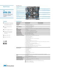
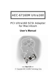
CONSOLEMgmt<strong>VTrak</strong> <strong>M610p</strong> <strong>Product</strong> <strong>Manual</strong><strong>VTrak</strong> Overview<strong>VTrak</strong> provides data storage solutions for applications where high performanceand data protection are required. The failure of any single drive will not affectdata integrity or accessibility of the data in a RAID protected logical drive.Figure 1. <strong>VTrak</strong> <strong>M610p</strong> front viewDrive Carrier LEDsDrive CarriersPower and Status LEDsA defective drive may be replaced without interruption of data availability to thehost computer. If so configured, a hot spare drive will automatically replace afailed drive, securing the fault-tolerant integrity of the logical drive. The selfcontainedhardware-based RAID logical drive provides maximum performance ina compact external chassis.Figure 2. <strong>VTrak</strong> <strong>M610p</strong> rear viewRAID ControllerPower Supply 1 Cooling Unit 1 Cooling Unit 2 Power Supply 22
Chapter 1: Introduction to <strong>VTrak</strong>Architectural DescriptionThe <strong>VTrak</strong> <strong>M610p</strong> is a parallel SCSI subsystem suitable for Direct AttachedStorage (DAS).The <strong>M610p</strong> subsystem supports:• 1.5 Gb/s SATA disk drives• 3.0 Gb/s SATA disk drivesAll <strong>M610p</strong> enclosure includes a mid-plane, RAID controller, power and coolingunits, and enclosure processor all in one cable-less chassis design. Multiple fansand power supplies provide redundancy to ensure continued usage duringcomponent failure. The RAID controller is hardware based and controls all logicaldrive functions transparently to the host system. <strong>VTrak</strong> appears to the computer’soperating system as a standard SCSI drive or drives.Features and BenefitsHighlights• 16 hot-swappable drive bays in a robust 3U rackmount chassis withredundant, hot-swappable power and cooling modules• Supports Serial ATA (SATA) 1.5 Gb/s and 3 Gb/s drives simultaneously inthe same system• Dual SCSI U320 host ports provide high-availability DAS• Simplified remote management with a comprehensive embedded webbasedmanagement via Ethernet—WebPAM PROe. Command LineInterface/Utility via DB9 Serial Port• Three years complete system limited warranty includes 24 x 7 email andphone support with highly experienced technical support technicians and anadvanced replacements program• Support for the latest RAID technology—RAID 6—Protection from acatastrophic double drive failure• Resilient data protection features such as Predictive Data Migration andPerfectRAID provide rock solid data protection• LUN Mapping and Masking bring flexibility for multiple application and OSsupport on the same storage subsystem• Open architecture, industry’s most comprehensive support for SATA harddrives and standards-based management interfaces including SNMP, CIM,and WBEM3
<strong>VTrak</strong> <strong>M610p</strong> <strong>Product</strong> <strong>Manual</strong>• Support for the industry standard Disk Data Format (DDF from SNIA)ensures interoperability and drive roaming even among different RAIDvendorsSubsystem and Controller FeaturesDrive Support: Up to sixteen 3.5" x 1" hard disk drives: SATA II 3Gb/s and1.5Gb/s.Supports any mix of SATA II 3 Gb/s or 1.5 Gb/s drives simultaneously in thesame system. Staggered physical drive spin-up.External I/O Ports: Dual SCSI U320 VHDCI host ports.Data Cache: Shared 256 MB predictive data cache (expandable to 1 GB);Automatic write cache destaging.Optional Battery Backup Unit (BBU) powers the data cache up to 72-hours in theevent of a power failure.Operational FeaturesRAID Levels: RAID 0, 1, 1E, 5, 6, 10, and 50 – Any combination of these RAIDlevels can exist at the same time.Configurable RAID stripe size: 64 KB, 128 KB, 256 KB, 512 KB, and 1 MB stripesize per logical drive.Background task priority tuning: Adjustment of minimum I/O reserved for serveruse during all background tasks.Hot spares: Multiple global or dedicated hot-spare drives with revert option.Maximum LUNs per subsystem: 256 in any combination of RAID levels.Maximum LUNs per array: 32 logical drives (LUNs). Supports LUN carving byallowing an array to be divided into multiple logical drives. Supports out-of-orderlogical drive deletion and re-creation.Max LUNs per Target ID: Up to 64, depending on host side driver and operatingsystem.LUN Masking and Mapping: Supports multiple hosts.Disk Data Formats: Supports Disk Data Format (DDF) for industry-widestandardization and drive roaming between <strong>VTrak</strong> systems.Background Activities: Media Patrol, background synchronizing, disk arrayrebuild, Redundancy Check, SMART condition pooling, Online CapacityExpansion (OCE), RAID Level Migration (RLM). <strong>Inc</strong>ludes priority control, ratecontrol, and watermarking per BGA in disk and NVRAM.4
Chapter 1: Introduction to <strong>VTrak</strong>Foreground Activities: Disk array initialization.Physical Drive Error Recovery: Predictive Data Migration (PDM), replaces unhealthydisk member in array, while maintaining normal array status during thedata transition. Bad Sector Mapping, Media Patrol, SMART, Hard/Soft Reset torecover HD from bad status, HD Power-control to recover HD from hung status.Array Error Recovery: Data recovery from bad sector or failed HD for redundantRAID, RAID 5/6 inconsistent data Prevent (Write Hole Table), Data content ErrorPrevent (Read/Write Check Table) NVRAM event logging.SCSI Commands: Supports extensive SCSI command set equivalent to SCSI/FChard disk drives. Variable sector size (512 byte to 4 KB) to break OS 2TBlimitation. 16 byte CDB support for 64-bit LBA addressing.ManagementSupported Operating Systems: Windows 2000 Server, Windows 2003 Server,Linux (Red Hat, SuSE), Macintosh OS X, Solaris.Management Tools: WebPAM PROe via out-of-band Ethernet. OS independent,localized in multiple languages, SSL Security support. Command Line Interface(CLI) and Command Line Utility (CLU) via DB9 Serial Port or Telnet.Standard Management Protocols: SNMP, WBEM/CIMRAID Creation: Automatic, Express, and Advanced configuration support fornovice to skilled users.Management Interfaces: WebPAM PROe, CLU, CLI, audible (buzzer) and visible(LEDs) alarms.Management Protocols: Embedded web server and management support—nohost agent needed. Ethernet, DB9 serial port, SNMP, SSL, Telnet, Email.SpecificationsCurrent (maximum): 8 A @ 100 VAC or 4 A @ 240 VAC Current rating with twopower cords.Power Consumption: 73 W (not including disk drives).Power Supply: Dual 400 W, 100-240 VAC auto-ranging, 50-60 Hz, dual hot swapand redundant with PFC, N+1 design.Operating Temperature: 5° to 40°C operational (-40° to 60°C non-operational)Relative Humidity: Maximum 95 percent.Vibration: Random, 0.21 grms, 5-500Hz, 30 Mins, X, Y, Z axis.5
<strong>VTrak</strong> <strong>M610p</strong> <strong>Product</strong> <strong>Manual</strong>Dimensions (H x W x D): 13.1 x 44.6 x 56.1 cm (5.2 x 17.6 x 22.1 in)Net Weight (subsystem only): 26.7 kg (58.7 lb) without drives, 34.7 kg (76.3 lb)with 16 drives, assuming 0.5 kg (1.1 lb) per drive.Gross Weight (including carton): 30 kg (66.1 lb) without drives.Safety: CE, FCC Class A, VCCI, C-Tick, cUL, TUV, CB, BSMI.Warranty and SupportWarranty: Three years complete system limited warranty.Support: 24 x 7 email and phone support (Americas and EMEA only). 24 x 7access to <strong>Promise</strong> support site for drivers, firmware, compatibility. Advancedreplacements program.FCC StatementThis device complies with Part 15 of the FCC Rules. Operation is subject to thefollowing two conditions: (1) this device may not cause harmful interference, and(2) this device must accept any interference received, including interference thatmay cause undesired operation.CE StatementWarning: This is a class A product. In a domestic environment this product maycause radio interference in which case the user may be required to takeadequate measures.MIC Statement6
Chapter 2: <strong>VTrak</strong> InstallationThis chapter covers the following topics:• Unpacking the <strong>VTrak</strong> (below)• Mounting <strong>VTrak</strong> in a Rack (page 8)• Installing Disk Drives (page 10)• Making Management and Data Connections (page 13)• Making Serial Cable Connections (page 15)• Connecting the Power (page 16)Unpacking the <strong>VTrak</strong>The <strong>VTrak</strong> box contains the following items:• <strong>VTrak</strong> Unit• Quick Start Guide• Null Modem Cable• Left and right center-mount brackets• Left and right mounting rails• 1.0m External VHDCI SCSI cable (2)• Screws for disk drives(66, including 2 spares)• 1.5m (4.9 ft) Power cords (2for US and 2 for Europe)• CD with SNMP files, <strong>Product</strong><strong>Manual</strong> and Quick Start GuideWarningThe electronic components within the <strong>VTrak</strong> disk array aresensitive to damage from Electro-Static Discharge (ESD).Observe appropriate precautions at all times when handling the<strong>VTrak</strong> or its subassemblies.ImportantUse the following categories of network cables with <strong>VTrak</strong>:• Cat 6, preferred• Cat 5E, minimum7
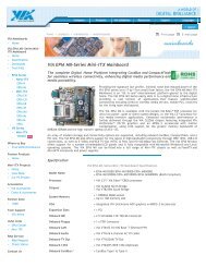
<strong>VTrak</strong> <strong>M610p</strong> <strong>Product</strong> <strong>Manual</strong>Mounting <strong>VTrak</strong> in a RackThe <strong>M610p</strong> subsytems installs to the rack using the supplied mounting rails. Youcan also use your existing rails.Figure 1. <strong>VTrak</strong> <strong>M610p</strong> mounted in a rack with the supplied railsVertical Rack Post<strong>VTrak</strong> <strong>M610p</strong>Handles mountoutside the rack postMounting rails (included)mount inside the rack postTo install the <strong>VTrak</strong> enclosure into a rack with the supplied mounting rails:1. Check the fit of the mounting rails in your rack system.2. Adjust the length of the mounting rails as needed.3. Attach the mounting rail assemblies to the inside of the rack posts, using theattaching screws from your rack system.Be sure the support is on the bottom facing inward.4. Square the rail assemblies in the rack.5. Tighten the adjustment screws and the attaching screws.6. Place the <strong>VTrak</strong> subsystem onto the rails.7. Secure the <strong>VTrak</strong> subsystem to the rack through each handle, using theattaching screws from your rack system.8Cautions• At least two persons are required to safely lift, place, andattach the <strong>VTrak</strong> enclosure into a rack system.• Do not lift or move the <strong>VTrak</strong> enclosure by the handles, powersupplies or the controller units. Hold the enclosure itself.• Do not install the <strong>VTrak</strong> enclosure into a rack without rails tosupport the enclosure.
Chapter 2: <strong>VTrak</strong> InstallationFigure 2. Rack mount assembly diagramRack front postRack back postRail attaching screw(not included)Rail attaching screw(not included)Front railRear railFlangeSupportInside of postRail adjustment screwRail adjustment screwInside of post9
<strong>VTrak</strong> <strong>M610p</strong> <strong>Product</strong> <strong>Manual</strong>Installing Disk DrivesYou can populate the <strong>VTrak</strong> with 3.5-inch, 1.5 Gb or 3.0 Gb SATA drives. Foroptimal performance, install physical drives of the same model and capacity. Thedrives’ matched performance allows the logical drive to function better as a singledrive. The table below shows the number of drives required for each RAID level.Level Number of Drives Level Number of DrivesRAID 0 1 or more RAID 6 4 to 16RAID 1 2 only RAID 10 4 or more*RAID 1E 2 or more RAID 50 6 or moreRAID 5 3 to 16* Must be an even number of drives.NoteUnlike other <strong>VTrak</strong> models, the <strong>M610p</strong> does not support ParallelATA disk drives. There is no PATA-to-SATA adapter available forthese models.Drive Slot NumberingYou can install any suitable disk drive into any slot in the enclosure. The diagrambelow shows how <strong>VTrak</strong>’s drive slots are numbered. Slot numbering is reflectedin the WebPAM PROe and CLU user interfaces.Figure 3. <strong>VTrak</strong> <strong>M610p</strong> drive slot numbering1 2 3 456789 10 11 1213 14 15 1610
Chapter 2: <strong>VTrak</strong> InstallationInstall all of the drive carriers into the <strong>VTrak</strong> enclosure to ensure proper airflow,even if you do not populate all the carriers with disk drives.Installing Disk Drives1. Remove a disk drive carrier.2. Carefully lay the disk drive into the drive carrier at the front, so that the screwholes on the bottom line up.3. Insert the screws through the holes in the drive carrier and into the bottom ofthe disk drive. See Figure 4.• Install only the counter-sink screws supplied with the <strong>VTrak</strong>.• Install four screws per drive.• Snug each screw. Be careful not to over-tighten.4. Reinstall the drive carrier into the <strong>VTrak</strong> chassis.Repeat steps 1 through 4 until all of your disk drives are installed.Figure 4. <strong>VTrak</strong> <strong>M610p</strong> drive carrier mounting holesSATA Drive Mounting HolesWARNING:Counter-sink screws only.SATA Drive Mounting Holes11
<strong>VTrak</strong> <strong>M610p</strong> <strong>Product</strong> <strong>Manual</strong>Figure 5. SATA Disk Drives mount at the front of the carrierSerial ATA Disk Drive12
Chapter 2: <strong>VTrak</strong> InstallationMaking Management and Data ConnectionsConfiguring Direct Attached StorageThis arrangement requires:• A network switch• A network interface card (NIC) in the PC• A SCSI HBA card in the PC• A SCSI cable that fits your HBA card and has a VHDCI connector to fit the<strong>VTrak</strong> SCSI channelData PathTo establish the data path:Connect a SCSI cable to the Host PC’s SCSI HBA card and one of the <strong>VTrak</strong>’sSCSI channels.<strong>VTrak</strong>’s SCSI connectors are bi-directional. However, the internal terminationfeature works only on the “Out” connector. Internal termination is set to Automaticby default.To use the internal termination feature, attach the SCSI cable to the “In”connector. An external terminator is not required for this arrangement.If you plan to connect multiple <strong>VTrak</strong>s on a SCSI chain, connect the “Out”connector of the same SCSI channel on the first <strong>VTrak</strong> to “In” connector of aSCSI channel on the second <strong>VTrak</strong>.See “Setting SCSI Termination” on page 60 or page 149 for more information.Management PathTo establish the management path:Connect the PC’s standard NIC and <strong>VTrak</strong>’s Management Port to your networkswitch to establish the management path.13
CONSOLEMgmt<strong>VTrak</strong> <strong>M610p</strong> <strong>Product</strong> <strong>Manual</strong>Figure 6. <strong>VTrak</strong> <strong>M610p</strong> DAS connectionsNetworkSwitchIn connectorSCSI Channel(1 of 2)Management PortNICSCSI HBA Card<strong>VTrak</strong>PC/Server14
CONSOLEMgmtChapter 2: <strong>VTrak</strong> InstallationMaking Serial Cable ConnectionsThe RS-232 Serial connection enables the Command Line Interface (CLI) andCommand Line Utility (CLU) on your PC to monitor and control <strong>VTrak</strong>.Figure 7. Serial connector for <strong>VTrak</strong> <strong>M610p</strong>DB-9 SerialConnectorCONSOLEMgmtTo set up a serial cable connection:1. Attach a null-modem cable to the DB9 connector on the <strong>VTrak</strong>.2. Attach the other end of the null-modem cable to a serial port on the Host PCor Server.You will establish a serial connection on the Host PC or Server (see page 19). Atthis time, continue with “Connecting the Power” on page 16.15
<strong>VTrak</strong> <strong>M610p</strong> <strong>Product</strong> <strong>Manual</strong>Connecting the PowerPlug the power cords and switch on both power supplies on. When the power isswitched on, the LEDs on the front of the <strong>VTrak</strong> will light up.When boot-up is finished and the <strong>VTrak</strong> is functioning normally:• Controller Heartbeat LED blinks green seven times in three seconds, goesdark for six seconds, then repeats the blink pattern.• Power, FRU, and Logical Drive Status LEDs display green continuously.• RAID Controller LED flashes green if there is activity on a SCSI channel.Figure 8. <strong>VTrak</strong> <strong>M610p</strong> front panel LED displayPowerFRU StatusLogical Drive StatusRAID Controller ActivityReservedController HeartbeatThere are two LEDs on each Drive Carrier. They report the presence of powerand a disk drive, and the current condition of the drive.Figure 9. <strong>VTrak</strong> <strong>M610p</strong> disk carrier LEDsDisk StatusAfter a few moments the Power/Activity should display Green.Power/Activity16
Chapter 2: <strong>VTrak</strong> InstallationIf there is no disk drive in the carrier, the Disk Status LED and the Power/ActivityLED will remain dark.The Power/Activity LED flashes during drive activity.The Disk Status LED displays Green when a drive is present and configured.17
<strong>VTrak</strong> <strong>M610p</strong> <strong>Product</strong> <strong>Manual</strong>18
Chapter 3: <strong>VTrak</strong> SetupThis chapter covers the following topics:• Setting up the Serial Connection (below)• Choosing DHCP or a Static IP Address (page 20)• Setting up <strong>VTrak</strong> with the CLI (page 21)• Setting up <strong>VTrak</strong> with the CLU (page 22)• Creating Disk Arrays with WebPAM PROe (page 24)Setting up the Serial Connection<strong>VTrak</strong> has a Command Line Interface (CLI) to manage all of its functions,including customization. A subset of the CLI is the Command Line Utility (CLU), auser-level interface that manages your <strong>VTrak</strong> via your PC’s terminal emulationprogram, such as Microsoft HyperTerminal. This procedure uses the serial cableconnection you made. See “Making Serial Cable Connections” on page 15.1. Change your terminal emulation program settings to match the followingspecifications:• Bits per second: 115200• Data bits: 8• Parity: None• Stop bits: 1• Flow control: none2. Start your PC’s terminal VT100 or ANSI emulation program.3. Press Enter once to launch the CLI.4. At the Login prompt, type administrator and press Enter.5. At the Password prompt, type password and press Enter.At this point, you are in the CLI. You can continue using the CLI to makenetwork settings or you can switch to the CLU. Go to:• Setting up <strong>VTrak</strong> with the CLI (page 21)• Setting up <strong>VTrak</strong> with the CLU (page 22)19
<strong>VTrak</strong> <strong>M610p</strong> <strong>Product</strong> <strong>Manual</strong>Choosing DHCP or a Static IP AddressWhen you setup your <strong>VTrak</strong>, you have the option of:• Enabling DHCP and letting your DHCP server assign the IP address to the<strong>VTrak</strong>’s management port.• Specifying a static IP address for the <strong>VTrak</strong>’s management port.If you choose to enable DHCP, have your Network Administrator dedicate an IPaddress for the <strong>VTrak</strong>, linked to the <strong>VTrak</strong>’s MAC address. This action willprevent the DHCP server from assigning a new IP address when the <strong>VTrak</strong>restarts, with the result that users can no longer log in.To access the MAC address for <strong>VTrak</strong>’s management port:• In the CLI, type net and press Enter.• In the CLU Main Menu, highlight Network Management and press Enter.20
Chapter 3: SetupSetting up <strong>VTrak</strong> with the CLI1. Type the following string to set the system date and time, then press Enter.administrator@cli> date -a mod -d 2006/12/26 -t 14:50:05In the above example, the date and time are included as examples only.Your values will be different. Use yyyyy/mm/dd for the date and a 24-hourclock for the time.2. Type the following string to set the Management Port IP address and othersettings, then press Enter.administrator@cli> net -a mod -t mgmt -s "primaryip=192.168.10.87,primaryipmask=255.255.255.0, gateway=192.168.10.1"In the above example, the IP addresses and subnet mask are included asexamples only. Your values will be different.If you prefer to let your DHCP server assign the IP address, type thefollowing string, then press Enter.administrator@cli> net -a mod -t mgmt -s "dhcp=enable"Note that the IP address described above belongs to the <strong>VTrak</strong> subsystem,not to the RAID controller. Use this IP address to log into the <strong>VTrak</strong> overyour network.3. To verify the settings, type net and press Enter.administrator@cli> net===========================================CId Port Type IP Mask Gateway Link===========================================1 1 Mgmt 192.168.10.87 255.255.255.0 192.168.10.1 UpThis completes the Management port setup. Go to “Creating Disk Arrays withWebPAM PROe” on page 24.To see the full set of CLI commands, at the admin@cli> prompt, type help andpress Enter.21
<strong>VTrak</strong> <strong>M610p</strong> <strong>Product</strong> <strong>Manual</strong>Setting up <strong>VTrak</strong> with the CLU1. At the administrator@cli> prompt, type menu and press Enter.The CLU main menu appears.Figure 1. CLU main menu2. With Quick Setup highlighted, press Enter.The first Quick Setup screen enables you to make Date and Time settings.Setting system date and time1. Press the arrow keys to highlight System Date.2. Press the backspace key to erase the current date.3. Type the new date.4. Follow the same procedure to set the System Time.5. Press Ctrl-A to save these settings and move to the Management Portconfiguration screen.Making Management Port settingsBy default, DHCP is disabled on <strong>VTrak</strong> and the default Management Port IPaddress is set to 10.0.0.1.Use a new Management Port IP address to log into the <strong>VTrak</strong> over your network.<strong>Manual</strong> IP settingsTo make Management Port settings manually:1. Press the arrow keys to highlight IP Address.2. Press the backspace key to erase the current IP Address.3. Type the new IP Address.22
Chapter 3: Setup4. Follow the same procedure to specify the Subnet Mask, Gateway IPAddress and DNS Server IP Address.If you do not have a DNS server, skip the DNS Server IP address.5. Press Ctrl-A to save your settings.Automatic IP settingsTo make Management Port settings automatically:1. Press the arrow keys to highlight DHCP.2. Press the spacebar to toggle to Enable.3. Press Ctrl-A to save these settings.Viewing IP address and settingsTo view the current IP address and network settings when using DHCP:1. Press the arrow keys to highlight DHCP.2. Press the spacebar to toggle to Disable.The current Management Port settings are displayed.3. Press the spacebar to toggle DHCP back to Enable.4. Press Ctrl-A to save these settings and move to the RAID configurationscreen.Exiting the CLU1. Highlight Skip the Step and Finish and press Enter.2. Highlight Return to CLI and press Enter.This completes the Management Port setup. Go to “Creating Disk Arrays withWebPAM PROe” on page 24.23
<strong>VTrak</strong> <strong>M610p</strong> <strong>Product</strong> <strong>Manual</strong>Creating Disk Arrays with WebPAM PROeNoteYou can also use the CLU to create disk arrays and logical drives.See “Creating a Disk Array” on page 133 for more information.Setting up disk arrays with WebPAM PROe consists of the following actions:• Logging into WebPAM PROe (below)• Selecting a Language (page 26)• Creating a Disk Array (page 26)• Logging out of WebPAM PROe (page 30)• Using WebPAM PROe over the Internet (page 31)• Obtaining a Security Certificate (page 31)Logging into WebPAM PROe1. Launch your Browser.2. In the Browser address field, type in the IP address of the <strong>VTrak</strong> subsystem.Use the IP address you set in the CLI (page 21) or CLU (page 22). Note thatthe IP address shown below is only an example. The IP address you typeinto your browser will be different.Regular Connection• WebPAM PROe uses an HTTP connection. . . . . . . . . . . . . . . .http://• Enter the <strong>VTrak</strong>’s Management Port IP address . . . . 192.168.1.105Together, your entry looks like this:http://192.168.1.105Secure Connection• WebPAM PROe uses a secure HTTP connection. . . . . . . . . .https://• Enter the <strong>VTrak</strong>’s Management Port IP address . . . . 192.168.1.105Together, your entry looks like this:https://192.168.1.105NoteWhether you select a regular or a secure connection, your login toWebPAM PROe and your user password are always secure.24
Chapter 3: Setup3. When the log-in screen (Figure 2) appears:• Type administrator in the User Name field.• Type password in the Password field.• Click the Login button.The User Name and Password are case sensitive.4. Click the Login button.Figure 2. WebPAM PROe log-in screenAfter sign-in, the WebPAM PROe opening screen appears. If there are anyunconfigured physical drives in the enclosure, an Array Configuration menu willalso appear (see page 26).NoteMake a Bookmark (Netscape Navigator) or set a Favorite (InternetExplorer) of the Login Screen so you can access it easily nexttime.25
<strong>VTrak</strong> <strong>M610p</strong> <strong>Product</strong> <strong>Manual</strong>Selecting a LanguageWebPAM PROe displays in English, German, French, Italian, Japanese, ChineseTraditional, Chinese Simple, and Korean.1. Click Language on the WebPAM PROe Header.The language list appears in the Header.2. Click on the language you prefer.The WebPAM PROe user interface displays in the selected language.Figure 3. Clicking “Language” on the WebPAM PROe HeaderCreating a Disk ArrayOn a newly activated <strong>VTrak</strong> subsystem, there are no disk arrays or logical drives.To create a disk array:1. Click on the Disk Arrays icon, then click on the Create tab.The Array Configuration menu appears. See Figure 4.2. Choose one of the options:• Automatic – Creates a new disk array based on a default set ofparameters, including one logical drive. The number of unconfiguredphysical drives available determines the RAID level of the disk arrayand whether a spare drive is created. See page 27.• Express – Creates a new disk array based on the characteristics youspecify. You can create multiple logical drives. However, all of thelogical drives will be the same size and RAID level. See page 28.• Advanced – Enables you to directly specify all parameters for a newdisk array and its logical drives. See page 29.3. Click the Next button.Figure 4. The Array Configuration menu26
Chapter 3: SetupAutomaticWhen you choose the Automatic option, the following parameters appear on thescreen:• Disk Arrays – The number of physical drives in the disk array, their IDnumbers, configurable capacity, and the number of logical drives to becreated• Logical Drives – The ID number of the logical drive(s), their RAID level,capacity, and stripe size• Spare Drives – The physical drive slot number of the dedicated hot spareassigned to this disk array. A hot spare drive is created for all RAID levelsexcept RAID 0, when five or more unconfigured physical drives are availableIf you accept these parameters, click the Submit button.The new disk array appears in the Disk Array List on the Information tab.If you do NOT accept these parameters, use the Express (page 28) or Advanced(page 29) option to create your disk array.27
<strong>VTrak</strong> <strong>M610p</strong> <strong>Product</strong> <strong>Manual</strong>ExpressWhen you choose the Express option, a set of characteristics and optionsappears on the screen.1. Check the boxes to select any one or a combination of:• Redundancy – The array will remain available if a physical drive fails• Capacity – The greatest possible amount of data capacity• Performance – The highest possible read/write speed• Spare Drive – A hot spare drive is created when you selectRedundancy, Spare Drive, and five or more unconfigured physicaldrives are available2. In the Number of Logical Drives field, enter the number of logical drives youwant to make from this disk array.The maximum possible number of logical drives appears to the right of thisfield.3. From the Application Type menu, select an application that best describesyour intended use for this disk array:• File Server• Video Stream• Transaction Data• Transaction Log• Other4. Click the Update button.Or check the Automatic Update box and updates will occur automatically.The following parameters display:• Disk Arrays – The number of physical drives in the disk array, their IDnumbers, configurable capacity, and the number of logical drives to becreated• Logical Drives – The ID number of the logical drive(s), their RAID level,capacity, and stripe size• Spare Drives – The physical drive ID number of the dedicated hotspare assigned to this disk array (all RAID levels except RAID 0)If you accept these parameters, proceed to the next step.If you do NOT accept these parameters, review and modify your selectionsin the previous steps.5. When you are done, click the Submit button.The new disk array appears in the Disk Array List on the Information tab.28
Chapter 3: SetupAdvancedNoteFor an explanation of the parameters under the Advanced option,see “Chapter 7: <strong>Technology</strong> Background” on page 189.When you choose the Advanced option, the Step 1 – Disk Array Creation screendisplays.Step 1 – Disk Array Creation1. Enter a name for the disk array in the field provided.2. Check the box if you want to enable Media Patrol.For more information, see “Media Patrol” on page 208.3. Check the box if you want to enable PDM.For more information, see “Predictive Data Migration (PDM)” on page 209.4. Highlight physical drives you want in the disk array from the Available listand press the >> button to move them to the Selected list.You can also double-click them to move them.5. When you are done, click the Next button.Step 2 – Logical Drive CreationLogical Drive Creation enables you to specify logical drives under the new diskarray. Enter the information for a logical drive, then click the Update button. Ifthere is free capacity remaining, you can specify another logical drive now or waituntil later.6. Enter an alias for the logical drive in the field provided.7. Choose a RAID level for the logical drive from the dropdown menu.The choice of RAID levels depends the number of physical drives youselected.8. RAID 50 only – Specify the number of axles for your array.For more information on axles, see “RAID 50 Axles” on page 196.9. Specify a Capacity and the unit of measure (MB, GB, TB).This value will be the data capacity of the first logical drive in your new diskarray. If you specify less than disk array's maximum capacity, the remainderwill be available for additional logical drives which you can create later.10. Specify a Stripe size from the dropdown menu.64 KB, 128 KB, 256 KB, and 1 MB are available. 64 KB is the default.11. Specify a Sector size from the dropdown menu.512 B, 1 KB, 2 KB, and 4 KB are available. 512 B is the default.29
<strong>VTrak</strong> <strong>M610p</strong> <strong>Product</strong> <strong>Manual</strong>12. Specify a Read (cache) Policy from the dropdown menu.Read Cache, Read Ahead Cache, and No Cache are available. Read Aheadis the default.13. Specify a Write (cache) Policy from the dropdown menu.Write Back and Write Through (Thru) are available. Write Back is the default.14. Click the Update button.A new logical drive is displayed under New Logical Drives.Repeat the above steps to specify additional logical drives as desired.15. When you are done specifying logical drives, click the Next button.Step 3 – SummaryThe Summary lists the disk array and logical drive information you specified.16. To proceed with disk array and logical drive creation, click the Submitbutton.Logging out of WebPAM PROeThere are two ways to log out of WebPAM PROe:• Close your browser window• Click Logout on the WebPAM PROe bannerFigure 5. Clicking “Logout” on the WebPAM PROe bannerClicking Logout brings you back to the Login Screen. See page 25.After logging out, you must enter your user name and password in order to log inagain.30
Chapter 3: SetupUsing WebPAM PROe over the InternetThe above instructions cover connections between <strong>VTrak</strong> and your companynetwork. It is also possible to connect to a <strong>VTrak</strong> from the Internet.Your MIS Administrator can tell you how to access your network from outside thefirewall. Once you are logged onto the network, you can access the <strong>VTrak</strong> usingits IP address.While only a SCSI-capable PC can read and write data to the logical drives onthe <strong>VTrak</strong>, other PCs can monitor the <strong>VTrak</strong> from virtually any location.Obtaining a Security Certificate<strong>Promise</strong> <strong>Technology</strong> provides a default security certificate for the web server aswell as for internal data communication. However, in most cases it is better toinstall and verify your own certificate. And, if possible, verify your certificatethrough a certificate authority, such as Verisign or Thwate. See your MISAdministrator for guidance.To download your security certificate to WebPAM PROe, see “Making WebServer Settings” on page 64.31
<strong>VTrak</strong> <strong>M610p</strong> <strong>Product</strong> <strong>Manual</strong>32
Chapter 4: Management with WebPAM PROeThis chapter covers the following topics:• Logging into WebPAM PROe(page 34)• Selecting a Language (page 36)• Perusing the Interface (page 37)• Logging out of WebPAM PROe(page 41)• Working with the Storage Network(page 42)• Working with Subsystems (page 43)• Managing Users (page 53)• Managing the Network Connection(page 58)• Managing SCSI Connections(page 59)• Managing Storage Services (page 61)• Managing Software Services(page 63)• Exporting the User Database(page 71)• Importing a User Database(page 72)• Updating the Firmware (page 73)• Restoring Factory Defaults(page 74)• Clearing Statistics (page 75)• Shutting Down the Subsystem(page 76)• Restarting the Subsystem (page 77)• Managing Controllers (page 78)• Managing Enclosures (page 82)• Managing Physical Drives (page 87)• Managing Disk Arrays (page 92)• Managing Logical Drives(page 105)• Managing Spare Drives (page 111)• Working with the Logical DriveSummary (page 115)For information about <strong>VTrak</strong>’s audible alarm and LEDs, see “Chapter 8:Troubleshooting” on page 213.33
<strong>VTrak</strong> <strong>M610p</strong> <strong>Product</strong> <strong>Manual</strong>Logging into WebPAM PROeIn order to log into WebPAM PROe, you must first setup a network connectionbetween your Host PC and the <strong>VTrak</strong> subsystem, as described in “Chapter 3:<strong>VTrak</strong> Setup” on page 19.To log into WebPAM PROe:1. Launch your Browser.2. In the Browser address field, type in the IP address of the <strong>VTrak</strong>Management port.Note that the IIP address shown below is only an example. The IP addressyou type into your browser will be different.Regular Connection• WebPAM PROe uses an HTTP connection. . . . . . . . . . . . . . . .http://• Enter the <strong>VTrak</strong>’s Management Port IP address . . . . 192.168.1.105Together, your entry looks like this:http://192.168.1.105Secure Connection• WebPAM PROe uses a secure HTTP connection. . . . . . . . . .https://• Enter the <strong>VTrak</strong>’s Management Port IP address . . . . 192.168.1.105Together, your entry looks like this:https://192.168.1.105NoteWhether you select a regular or a secure connection, your login toWebPAM PROe and your user password are always secure.3. When the log-in screen (Figure 1) appears:• Type administrator in the User Name field.• Type password in the Password field.• Click the Login button.The User Name and Password are case sensitive.4. Click the Login button.34
Chapter 4: Management with WebPAM PROeFigure 1. The WebPAM PROe log-in screen35
<strong>VTrak</strong> <strong>M610p</strong> <strong>Product</strong> <strong>Manual</strong>Selecting a LanguageWebPAM PROe displays in English, German, French, Italian, Japanese, ChineseTraditional, Chinese Simple, and Korean.1. Click Language the WebPAM PROe Header.The language list appears in the Header.2. Click the language you prefer.The WebPAM PROe user interface displays in the selected language.Figure 2. Clicking “Language” in the Header36
Chapter 4: Management with WebPAM PROePerusing the InterfaceWebPAM PROe is browser-based RAID management software with a graphicuser interface.Figure 3. WebPAM PROe interfaceThere are four major parts to the graphic user interface:• Header (see page 38)• Tree (see page 39)• Management View (see page 40)• Event Frame (see page 40)37
<strong>VTrak</strong> <strong>M610p</strong> <strong>Product</strong> <strong>Manual</strong>Using the HeaderThe Header contains the following items:• Language – To change languages, see “Selecting a Language” on page 36.• View – To view the Event Frame, see “Viewing the Event Frame” onpage 40.• Storage Network – To view all of the <strong>VTrak</strong> subsystem enclosures currentlyaccessible the network, see “Working with the Storage Network” on page 42.• Contact Us – Click on Contact Us for a list of contact information, includingTechnical Support. Also see “Contacting Technical Support” on page 255.• Logout – To logout of WebPAM PROe, see “Logging out of WebPAMPROe” on page 41• Help – Click on Help in the Header to access the main online help menu.• About – Click on About in the Header to display the WebPAM PROesoftware version and build date.38
Chapter 4: Management with WebPAM PROeUsing Tree ViewTree View enables you to navigate around all components of the Subsystem,including SCSI management, network and service management, RAID controller,enclosure, physical drives, disk arrays, logical drives, and spare drives. Thefigure below shows the components of Tree View.Figure 4. WebPAM PROe Tree ViewName of logged-in userSubsystem IP address and modelPhysical Drivesin this EnclosureThe Administrative Tools section is different for the Super User than for otherusers. The remainder of the Tree is the same for all users.Management View displays information according to the item you select in TreeView.39
<strong>VTrak</strong> <strong>M610p</strong> <strong>Product</strong> <strong>Manual</strong>Using Management ViewManagement View provides the actual user interface with the <strong>VTrak</strong>, includingcreation, maintenance, deletion, and monitoring of disk arrays and logical drives.Function Tabs control specific actions and processes. This window changesdepending on which item you select in Tree View and which tab you select inManagement View itself.Click the Help button in Management View to access online help for the functionthat is currently displayed.Viewing the Event FrameTo view the Event Frame:1. Click on View in the Header.2. Click the Show Event Frame popup option.The <strong>VTrak</strong> user interface will display the Event Frame below ManagementView.3. Click View again to hide the Event Frame.In the event frame, events are listed and sorted by:• Item Number – A consecutive decimal number assigned to a specific event• Device – Battery, controller, logical drive, physical drive, port, etc.• Event ID – The hexadecimal number that identifies the specific type of event• Severity – Information, Warning, Minor, Major, Critical, and Fatal. Theseverity level is user-specified. See “Setting-up User Event Subscriptions”on page 54.• Time – Time and date of the occurrence• Description – A brief description of the eventSorting EventsYou can sort the events by Item Number, Device, Event ID, Severity, Time andDate, or Description.Click on the link at the top of the column by which you want to sort the events.After you click on the item, a triangle icon appears.• If the triangle points upward, the column is sorted low-to-high or old-to-new.• If the triangle points downward, the column is sorted high-to-low or new-toold.Click the link a second time to change to flip the triangle and reverse the sortsequence.40
Chapter 4: Management with WebPAM PROeLogging out of WebPAM PROeThere are two ways to log out of WebPAM PROe:• Close your browser window• Click Logout the WebPAM PROe banner (belowFigure 8. Clicking “Logout” in the Header)Clicking Logout brings you back to the Login Screen. After logging out, you mustenter your user name and password in order to log in again.41
<strong>VTrak</strong> <strong>M610p</strong> <strong>Product</strong> <strong>Manual</strong>Working with the Storage NetworkWhen you log into WebPAM PROe, you access a specific <strong>VTrak</strong> subsystem. See“Logging into WebPAM PROe” on page 34.The Storage Network feature enables you to access all of the <strong>VTrak</strong> subsytemswith a Management Port connection to your network.Each <strong>VTrak</strong> subsystem is identified by its Management Port IP address.Storage Network functions include:• Viewing other subsystems• Updating the list of subsystems• Logging into a subsystem• Hiding the other subsystemsViewing Other SubsytemsTo view the other <strong>VTrak</strong> subsytems the Storage Network:1. Click on Storage Network in the Header.2. Click the Show Network Subsystems popup option.The list will show all subsystems the network at the time the GUI waslaunched.Updating the List of SubsystemsTo update the list of the <strong>VTrak</strong> subsytems the Storage Network:Click the Discover button at the bottom of the subsystem list.Logging into a SubsystemTo log into any of the displayed <strong>VTrak</strong> subsystems:1. In Tree View, click the Subsystem icon of the subsystem you want to see.If your user name and password do not match the subsystem you arelogging into, the log in screen will appear.2. Log into the new subsystem, as needed.Hiding the Other SubsystemsTo hide the other <strong>VTrak</strong> subsystems the Storage Network:1. Click on Storage Network in the Header.2. Click the Hide Network Subsystems popup option.42
Working with SubsystemsChapter 4: Management with WebPAM PROeA <strong>VTrak</strong> subsystem is identified by its Management Port IP address. Subsystemfunctions include:• Viewing Subsystem Information (page 43)• Setting an Alias for the Subsystem (page 43)• Setting Subsystem Date and Time (page 44)• Viewing the Runtime Event Log (page 44)• Saving the Runtime Event Log (page 45)• Clearing the Runtime Event Log (page 45)• Viewing NVRAM Events (page 45)• Saving NVRAM Events (page 46)• Clearing NVRAM Events (page 46)• Viewing Current Background Activities (page 46)• Making Background Activity Settings (page 47)• Running Background Activities (page 48)• Running Media Patrol (page 48)• Running PDM (page 48)• Viewing Scheduled Activities (page 49)• Scheduling an Activity (page 49)• Deleting a Scheduled Activity (page 50)• Viewing Lock Status (page 50)• Setting the Lock (page 51)• Renewing the Lock (page 51)• Releasing the Lock (page 51)Viewing Subsystem InformationTo view information about a subsystem, click the SubsystemView. Management View displays the subsystem information.icon in TreeSetting an Alias for the SubsystemAn alias is optional. To set an alias for this subsystem:1. In Tree View, click the Subsystem icon.2. In Management View, click the Settings tab.43
<strong>VTrak</strong> <strong>M610p</strong> <strong>Product</strong> <strong>Manual</strong>3. Enter a name into the Alias field.Maximum of 48 characters. Use letters, numbers, space between words,and underscore.4. Click the Submit button.Setting Subsystem Date and TimeTo set a Date and Time for this subsystem:1. In Tree View, click the Subsystem icon.2. In Management View, click the Settings tab dropdown menu and select Dateand Time Settings.3. Under Subsystem Date, select the Month and Day from the dropdownmenus.4. Type the current year into the Year field.5. Under Subsystem Time, select the Hour, Minutes and Seconds from thedropdown menus.6. Click the Submit button.Viewing the Runtime Event LogRuntime Events lists information about the 1023 most recent runtime eventsrecorded since the system was started. To view runtime events:1. In Tree View, click the Subsystem icon.2. In Management View, click the Events tab dropdown menu and selectRuntime Events.Events are displayed by:• Item Number – A consecutive decimal number assigned to a specificevent• Device – Battery, controller, logical drive, physical drive, port, etc.• Event ID – The hexadecimal number that identifies the specific type ofevent• Severity – Information, Warning, Minor, Major, Critical, and Fatal. Theseverity level is user-specified. See “Setting-up User EventSubscriptions” on page 54.• Time – Time and date of the occurrence• Description – A brief description of the event3. Click on the link at the top of the column by which you want to sort theevents. After you click on the item, a triangle icon appears.44
Chapter 4: Management with WebPAM PROe• If the triangle points upward, the column is sorted low-to-high or old-tonew.• If the triangle points downward, the column is sorted high-to-low or newto-old.Click the link a second time to change to flip the triangle and reverse the sortsequence.Saving the Runtime Event LogTo save the runtime event log as a text file:1. In Tree View, click the Subsystem icon.2. In Management View, click the Events tab dropdown menu and selectRuntime Events.3. Click the Save Event Log button.4. In the File Download dialog box, click the Save button.5. In the Save dialog box, name the file, navigate to the folder where you wantto save the log file, and click the Save button.Clearing the Runtime Event LogTo clear the runtime event log:1. In Tree View, click the Subsystem icon.2. In Management View, click the Events tab dropdown menu and selectRuntime Events.3. Click the Clear Event Log button.4. In the Confirmation dialog box, type confirm and click the OK button.Viewing NVRAM EventsNVRAM Events lists information about the 191 most recent important events.NVRAM events are stored in non-volatile memory. To view runtime events:1. In Tree View, click the Subsystem icon.2. In Management View, click the Events tab dropdown menu and selectSystem Events in NVRAM.Events are displayed by:• Item Number – A consecutive decimal number assigned to a specificevent• Device – Battery, controller, logical drive, physical drive, port, etc.• Event ID – The hexadecimal number that identifies the specific type ofevent45
<strong>VTrak</strong> <strong>M610p</strong> <strong>Product</strong> <strong>Manual</strong>• Severity – Information, Warning, Minor, Major, Critical, and Fatal. Theseverity level is user-specified. See “Setting-up User EventSubscriptions” on page 54.• Time – Time and date of the occurrence• Description – A brief description of the event3. Click on the link at the top of the column by which you want to sort theevents. After you click on the item, a triangle icon appears.• If the triangle points upward, the column is sorted low-to-high or old-tonew.• If the triangle points downward, the column is sorted high-to-low or newto-old.Click the link a second time to change to flip the triangle and reverse the sortsequence.Saving NVRAM EventsTo save the NVRAM event log as a text file:1. In Tree View, click the Subsystem icon.2. In Management View, click the Events tab dropdown menu and selectSystem Events in NVRAM.3. Click the Save Event Log button.4. In the File Download dialog box, click the Save button.5. In the Save dialog box, name the file, navigate to the folder where you wantto save the log file, and click the Save button.Clearing NVRAM EventsTo clear the NVRAM event log:1. In Tree View, click the Subsystem icon.2. In Management View, click the Events tab dropdown menu and selectSystem Events in NVRAM.3. Click the Clear Event Log button.4. In the Confirmation dialog box, type confirm and click the OK button.Viewing Current Background ActivitiesTo view the current background activities:1. In Tree View, click the Subsystem icon.2. In Management View, click the Background Activities tab.A list of current background activities appears, including:46
Chapter 4: Management with WebPAM PROe• Rebuild• PDM – Predictive Data Migration• Synchronization• Redundancy Check• Migration• Transition• Initialization• Media PatrolMaking Background Activity SettingsTo make settings for background activities:1. In Tree View, click the Subsystem icon.2. In Management View, click the Background Activities tab and select Settingsfrom the dropdown menu.3. Click the dropdown menu to choose a priority of Low, Medium, and High forthe following functions:• Rebuild – Rebuilds the data from a failed drive in a disk array• Synchronization – Checks the data integrity on disk arrays• Initialization – Sets all data bits in the logical drive to zero• Redundancy Check – Checks, reports and can correct datainconsistencies in logical drives• Migration – Change RAID level or add physical dries to disk arrays• PDM – Looks for bad blocks the physical drives of disk arrays• Transition – Returns a revertible spare drive to spare statusThe rates are defined as follows:• Low – Fewer resources to activity, more to data read/write.• Medium – Balance of resources to activity and data read/write.• High – More resources to activity, fewer to data read/write.4. Highlight the following PDM trigger settings and type a value into thecorresponding field:• Reassigned Block Threshold – 1 to 512 blocks• Error Block Threshold – 1 to 1024 blocks5. Check to enable or uncheck to disable the following functions:• Media Patrol – Checks the magnetic media on physical drives• Auto Rebuild – If there is a spare drive of adequate capacity, a criticaldisk array will begin to rebuild automatically. If not spare drive is47
<strong>VTrak</strong> <strong>M610p</strong> <strong>Product</strong> <strong>Manual</strong>available, the disk array will begin to rebuild as soon as you replace thefailed physical drive with an unconfigured physical drive of equal orgreater size.6. Click the Submit button to save your settings.Running Background ActivitiesTo run a background activity from the Background Activities tab:1. In Tree View, click the Subsystem icon.2. In Management View, click the Background Activities tab and select one ofthe following from the dropdown menu.• Media Patrol – See “Running Media Patrol” on page 48• Rebuild – See “Rebuilding a Disk Array” on page 101• PDM – See “Running PDM” on page 48• Transition – See “Transitioning a Disk Array” on page 103• Initialization – See “Initializing a Logical Drive” on page 107• Redundancy Check – See “Running Redundancy Check” on page 1083. In the next screen, make the choices as requested.4. Click the Start button.Running Media PatrolMedia Patrol checks the magnetic media on physical drives. When it finds thespecified number of bad blocks, it will trigger PDM. See “Making BackgroundActivity Settings” on page 47 and “Running PDM” on page 48.You can schedule Media Patrol to run automatically, see “Scheduling an Activity”on page 49.To run Media Patrol:1. In Tree View, click the Subsystem icon.2. From the dropdown menu on the Background Activities tab, select StartMedia Patrol.3. In the next screen, click the Start button.Running PDMPredictive Data Migration (PDM) migrates data from the suspect physical drive toa spare disk drive, similar to Rebuilding. But unlike Rebuilding, PDM acts beforethe disk drive fails and your Logical Drive goes Critical.You an also run PDM on a specific disk array, see “Running PDM on a DiskArray” on page 102.48
Chapter 4: Management with WebPAM PROeAlso see “Predictive Data Migration (PDM)” on page 209.To run PDM:1. In Tree View, click the Subsystem icon.2. In Management View, click the Background Activities tab and select StartMedia Patrol from the dropdown menu.3. In the next screen, select the Source and Target physical drives.The suspect physical drive is the source. The replacement physical drive isthe target.4. Click the Start button.Viewing Scheduled ActivitiesTo view scheduled activities for this subsystem:1. Click the Subsystem icon Tree View.2. Click the Scheduler tab in Management View.Scheduling an ActivityTo set a scheduled activity for this subsystem:1. Click the Subsystem icon Tree View.2. From the dropdown menu on the Scheduler tab, choose an item:• Media Patrol. See “Running Media Patrol” on page 48• Redundancy Check. See “Running Redundancy Check” on page 108• Battery Reconditioning. See “Reconditioning a Battery” on page 85• Spare Drive Check. See “Running Spare Check” on page 1143. In the Scheduler dialog box, check the Enable This Schedule box.4. Select a start time (24-hour clock).5. Select a Recurrence Pattern.• Daily – Enter the number of days between events.• Weekly – Enter the number of weeks between events and select whichdays of the week.• Monthly – Select a calendar day of the month (1 – 31).If you select a higher number than there are days in the current month, theactual start date will occur at the beginning of the following month.Or, select a day of the week and select the first, second, third, fourth, or lastoccurrence of that day in the month.Then, select the months in which you want the activity to occur.6. Select a Range of Occurrence.49
<strong>VTrak</strong> <strong>M610p</strong> <strong>Product</strong> <strong>Manual</strong>• Start-from date. The default is today's date.• End-on date.Select No End Date (perpetual).Or, select a number of occurrences for this activity.Or, select a specific end date. The default is today's date.7. For Redundancy Check only:• Choose the Auto Fix option. This feature attempts to repair the problemwhen it finds an error.• Choose the Pause on Error option. This feature stops the process whenit finds an error• Check the boxes beside the logical drives (all except RAID 0) to whichthis activity will apply.Each logical drive can have only one scheduled Redundancy Check.NoteYou can schedule only ONE Redundancy Check for each logicaldrive.8. Click the Submit button.Deleting a Scheduled ActivityTo delete a scheduled activity for this subsystem:1. Click the Subsystem icon Tree View.2. From the dropdown menu on the Scheduler tab, choose Delete Schedules.3. Check the box to the left of the schedule you want to delete.4. Click the Submit button.Viewing Lock StatusThe lock prevents other sessions (including by the same user) from making aconfiguration change to the controller until the lock expires or a forced unlock isdone.To view the lock status for this subsystem:1. Click the Subsystem icon Tree View.2. Click the Lock tab in Management View.The following information is displayed:• Lock Status – The User who set (owns) the current lock.50
Chapter 4: Management with WebPAM PROe• Expiration Time – Amount of time left until the lock automaticallyreleases.• Expire At Time – The date and time when the lock will automaticallyrelease.Setting the LockThe lock prevents other sessions (including by the same user) from making aconfiguration change to the controller until the lock expires or a forced unlock isdone.You can set the lock to last from one minute to one day. To set the lock for thissubsystem:1. Click the Subsystem icon Tree View.2. Click the Lock tab in Management View.3. Click the Lock option.4. Enter a time interval between 1 and 1440 minutes (one day) that you wantthe lock to stay active.5. Click the Submit button.Renewing the LockThe lock prevents other sessions (including by the same user) from making aconfiguration change to the controller until the lock expires or a forced unlock isdone.Renewing the lock extends the period of time the controller remains locked. Torenew an existing lock for this subsystem:1. Click the Subsystem icon Tree View.2. Click the Lock tab in Management View.3. Click the Renew option.4. Enter a time interval between 1 and 1440 minutes (one day) that you wantthe lock to stay active.The renew time replaces the previous Expiration Time.5. Click the Submit button.Releasing the LockThe lock prevents other sessions (including by the same user) from making aconfiguration change to the controller until the lock expires or a forced unlock isdone.51
<strong>VTrak</strong> <strong>M610p</strong> <strong>Product</strong> <strong>Manual</strong>When the user who locked the controller logs out, the lock is automaticallyreleased. You can also release the lock before the scheduled time.To release the lock for this subsystem:1. Click the Subsystem icon Tree View.2. Click the Lock tab in Management View.If you are the User who set the lock, click the Unlock option.If another User set the lock and you are a Super User, click the Unlockoption and check the Force Unlock box.3. Click the Submit button.52
Chapter 4: Management with WebPAM PROeManaging UsersUser Management includes all functions dealing with user accounts. Functionsinclude:• Viewing User Information (page 53)• Making User Settings (page 53)• Making Your Own User Settings (page 54)• Setting-up User Event Subscriptions (page 54)• Changing Another User’s Password (page 55)• Changing Your Own Password (page 55)• Creating a User (page 56)• Deleting a User (page 57)• Viewing User Sessions (page 57)• Logging out Other Users (page 57)Viewing User InformationThe view a list of users, their status, access privileges, display name, and emailaddress:1. Click the Subsystem icon in Tree View.2. Click the Administrative Tools icon.3. Click the User Management icon.The Information tab appears in Management View.Making User SettingsTo change settings of other users:1. Log into WebPAM PROe as the Administrator or a Super User.2. Click the Subsystem icon in Tree View.3. Click the Administrative Tools icon.4. Click the User Management icon.5. On the Information tab, click the link of the user whose settings you want tochange.The Settings screen for the selected user displays.6. Make the following settings as needed.• Check the Enable box to enable this user.• Uncheck the box to disable this user.• Enter or change the display name.53
<strong>VTrak</strong> <strong>M610p</strong> <strong>Product</strong> <strong>Manual</strong>• Enter or change the email address.• From the Privilege dropdown menu, choose a new level.See “List of User Privileges” on page 567. Click the Submit button.The Administrator or Super User can change another user’s password. See“Changing Another User’s Password” on page 55 for more information.Making Your Own User SettingsTo change your own user settings:1. Log into WebPAM PROe under your own user name.2. Click the Subsystem icon in Tree View.3. Click the Administrative Tools icon.4. Click the User Management icon.5. Click the Settings tab in Management View.6. Enter or change the display name or mail address.7. Click the Submit button.Setting-up User Event SubscriptionsAn event subscription enables a user to receive email messages about eventstaking place in the <strong>VTrak</strong> subsystem. To make or change user eventsubscriptions:1. Click the Subsystem icon in Tree View.2. Click the Administrative Tools icon.3. Click the User Management icon.4. Click the Event Subscription tab in Management View.5. Check the box to enable event notification.6. Under the subheadings, select the lowest level of Severity to be reported foreach event. The selected level plus all higher levels of Severity will bereported.• Information – Information only, no action is required• Warning – User can decide whether or not action is required• Minor – Action is needed but the condition is not a serious at this time• Major – Action is needed now• Critical – Action is needed now and the implications of the condition areserious54
Chapter 4: Management with WebPAM PROe• Fatal – Non-Recoverable error or failure has occurred• None – Deactivates this event for notification purposes7. Click the Submit button.The user’s account must have an email address. See “Making User Settings” onpage 53.For information about the email service, see “Making Email Settings” on page 63.To send a test message to the email address in the listed under General Info,click the Test Email button.Changing Another User’s PasswordTo change a user’s password:1. Log into WebPAM PROe as the Administrator or a Super User.2. Click the Subsystem icon in Tree View.3. Click the Administrative Tools icon.4. Click the User Management icon.5. In the list of users, click the link of the user whose settings you want tochange.The Settings screen for the selected user displays.6. Click the Password tab in Management View.7. Enter the new password in the New Password field.8. Enter the new password in the Retype Password field.9. Click the Submit button.Changing Your Own PasswordTo set or change your own password:1. Log into WebPAM PROe under your own user name.2. Click the Subsystem icon in Tree View.3. Click the Administrative Tools icon.4. Click the User Management icon.5. Click the Password tab in Management View.6. Enter the current password in the Old Password field.If you do not have a password, leave this field blank.7. Enter the new password in the New Password field.8. Enter the new password in the Retype Password field.55
<strong>VTrak</strong> <strong>M610p</strong> <strong>Product</strong> <strong>Manual</strong>9. Click the Submit button.Creating a UserTo create a user:1. Log into WebPAM PROe as the Administrator or a Super User.2. Click the Subsystem icon in Tree View.3. Click the Administrative Tools icon.4. Click the User Management icon.5. Click the Create tab in Management View.6. Enter a user name in the User Name field.7. Enter a password for this user in the New Password and Retype Passwordfields.A password is optional. If you do not specify a password, log into WebPAMPROe with the User Name and leave the password field blank.8. Enter a display name in the Display Name field.A display name is optional.9. Enter the user's email address in the Email Address field.An email address is required in order to receive email event notification.10. Select a privilege level from the Privilege dropdown menu.For definitions of each privilege level, see the List of User Privileges below.11. Check the Enabled box to enable this user on this subsystem.12. Click the Submit button.List of User Privileges• View – Allows the user to see all status and settings but not to make anychanges• Maintenance – Allows the user to perform maintenance tasks includingRebuilding, PDM, Media Patrol, and Redundancy Check• Power – Allows the user to create (but not delete) disk arrays and logicaldrives, change RAID levels, change stripe size; change settings ofcomponents such as disk arrays, logical drives, physical drives, and thecontroller.• Super – Allows the user full access to all functions including create anddelete users and changing the settings of other users, and delete disk arraysand logical drives. The default “administrator” account is a Super User.56
Chapter 4: Management with WebPAM PROeDeleting a UserThere will always be at least one Super User account. You cannot delete the useraccount you used to log in.To delete a user:1. Log into WebPAM PROe as the Administrator or a Super User.2. Click the Subsystem icon in Tree View.3. Click the Administrative Tools icon.4. Click the User Management icon.5. Click the Delete tab in Management View.6. Check the box to the left of the user you want to delete.7. Click the Submit button.8. Click OK in the confirmation box.Viewing User SessionsTo view the current sessions:1. Click the Subsystem icon in Tree View.2. Click the Administrative Tools icon.3. Click the User Management icon.4. Click the Sessions tab in Management View.Logging out Other UsersTo logout other users:1. Log into WebPAM PROe as the Administrator or a Super User.2. Click the Subsystem icon in Tree View.3. Click the Administrative Tools icon.4. Click the User Management icon.5. Click the Sessions tab in Management View.6. Check the box to the left of the user you want to log out.7. Click the Logout button.8. Click OK in the confirmation box.57
<strong>VTrak</strong> <strong>M610p</strong> <strong>Product</strong> <strong>Manual</strong>Managing the Network ConnectionThe network connection deals with network connections to the <strong>VTrak</strong>’sManagement Ports. Functions include:• Making Subsystem Management Port Settings (page 58)Making Subsystem Management Port SettingsWhen you log into the <strong>VTrak</strong> over your network, you use the management port.Before you change settings, please see “Choosing DHCP or a Static IP Address”on page 20.To make changes to the Subsystem Management Port settings:1. Click the Subsystem icon in Tree View.2. Click the Administrative Tools icon.3. Click the Network Management icon.4. Click the Port Configuration link in Management View.5. To enable DHCP, check the DHCP box.When DHCP is NOT enabled, enter:• Primary IP address• Primary subnet mask• Default gateway IP address• Enter a primary DNS server IP address.6. Click the Submit button.58
Chapter 4: Management with WebPAM PROeManaging SCSI ConnectionsFunctions include:• Viewing SCSI Channel Information (page 59)• Enabling SCSI Targets (page 59)• Setting SCSI Termination (page 60)• Viewing SCSI Target Information (page 60)Viewing SCSI Channel Information1. Click the Subsystem icon in Tree View.2. Click the Administrative Tools icon.3. Click on the SCSI Management icon.The Channel tab displays SCSI Channel Information:• Maximum Data Transfer Rate• Termination Status• List of currently enabled targetsTo see Target information, click the Target tab.Enabling SCSI TargetsTo enable a SCSI target:1. Click the Subsystem icon in Tree View.2. Click the Administrative Tools icon.3. Click on the SCSI Management icon.The Channel tab displays SCSI Channel Information:4. Click on the Channel 1 or the Channel 2 link.5. Check (click on) the TID box beside the target you want to enable.Checked means enabled, unchecked means disabled.6. Click the Submit button.Notes• You must make target settings for each SCSI channelseparately.• You must restart the <strong>VTrak</strong> for new settings to becomeeffective. See “Restarting the Subsystem” on page 77.59
<strong>VTrak</strong> <strong>M610p</strong> <strong>Product</strong> <strong>Manual</strong>Setting SCSI TerminationTo set Termination for the <strong>VTrak</strong> SCSI controller “Out” connectors:1. Click the Subsystem icon in Tree View.2. Click the Administrative Tools icon.3. Click on the SCSI Management icon.The Channel tab displays SCSI Channel Information:4. Click on the Channel 1 or the Channel 2 link.5. From the Termination dropdown menu, select Automatic, ON or OFF.Automatic means the termination function will set itself automatically.6. Click the Submit button.Cautions• Turn off termination only when the <strong>VTrak</strong> is NOT the lastdevice in the SCSI chain.• Internal termination only works on the “Out” SCSI connectors.Viewing SCSI Target Information1. Click the Subsystem icon in Tree View.2. Click the Administrative Tools icon.3. Click on the SCSI Management icon.The Channel tab displays SCSI Channel Information:4. Click on the Target tab.The Target tab displays information about the 16 SCSI targets on each ofthe two SCSI channels:• SCSI Port ID – 1 or 2• Target ID – 0 to 15• Status – Enabled or Disabled• Negotiated Transfer Rate – Data Transfer Rate in MB/s• Bus Width – Narrow or WideA value of N/A under Transfer Rate or Bus Width appears when the Target isdisabled. To enable a SCSI Target, see “Enabling SCSI Targets” onpage 59.60
Chapter 4: Management with WebPAM PROeManaging Storage ServicesThe Storage Services–LUN Map tab displays the Target IDs and LUNs assignedto each logical drive.For SCSI, LUN Mapping is the process of applying a LUN Map so that eachchannel can access the logical drive (target).Features include:• Viewing a LUN Map (page 61)• Editing a LUN Map (page 61)Viewing a LUN MapTo view the current LUN Map:1. Click the Subsystem icon in Tree View.2. Click the Administrative Tools icon.3. Click on the Storage Services icon.4. Click the LUN Map tab in Management View.Editing a LUN MapImportantYou must enable a Target before you assign a LUN to it. See“Enabling SCSI Targets” on page 59.To edit a LUN map:1. Click on the Subsystem icon in Tree view.2. Click on the Administrative Tools icon.3. Click on the Storage Services icon.4. Click the LUN Map tab in Management View.5. From the LUN Map tab dropdown menu, select Edit LUN Map.6. Select Port 1 or Port 2 from the Port ID dropdown menu.7. In the LUN Mapping and Masking table, select a Logical Drive ID with emptyTarget ID and LUN fields.8. Type a Target ID into the Target ID field.Target IDs range from 0 to 15.9. Type a LUN into the LUN field.61
<strong>VTrak</strong> <strong>M610p</strong> <strong>Product</strong> <strong>Manual</strong>LUNs range from 0 to 63. The number of available LUNs may be less,depending on the capability of your SCSI HBA card.You must enter different LUN numbers for each logical drive.10. Click the Submit button.LUN Mapping Parameters• Logical Drive ID – The disk array ID number.• RAID Level – RAID Level of the logical drive.• Capacity – Capacity of the logical drive.• WWN – World Wide Number of the logical drive.• Target ID – Active Target ID on this logical drive for the selected port.• LUN – Logical Unit Number on this logical drive for the selected port. Eachlogical drive has a unique LUN.62
Chapter 4: Management with WebPAM PROeManaging Software ServicesSoftware Services include the following functions:• Making Email Settings (page 63)• Making SLP Settings (page 64)• Making Web Server Settings (page 64)• Making Telnet Settings (page 66)• Making SNMP Settings (page 66)• Making CIM Settings (page 68)• Making Netsend Settings (page 69)Making Email SettingsThe Email sends notification messages to users. See Setting-up User EventSubscriptions (page 54).To make Email service settings:1. Click the Subsystem icon in Tree View.2. Click the Administrative Tools icon.3. Click the Email Setting link in Management View.4. Enter the IP address for your SMTP server.5. Enter server port number for your SMTP server.25 is the default.6. Select Yes to enable SMTP authentication or No to Yes.7. If you selected Yes for SMTP authentication, enter a Username andPassword in the fields provided.8. Enter an Email sender address (example: RAIDmaster@mycompany.com).9. Enter an Email subject (example: <strong>VTrak</strong> Status).10. Click the Submit button.Sending a Test MessageTo send one test message to the User currently logged into WebPAM PROe:1. Under Test Email, check the “Send A Test Email” box.2. Click the Submit button.If you do not receive the Test Email message, see your Network Administrator forassistance with the mail server setup, email accounts, and other issues.Changing the Startup Setting1. Under Startup Type:63
<strong>VTrak</strong> <strong>M610p</strong> <strong>Product</strong> <strong>Manual</strong>• Click on the Automatic option to start the service automatically duringsystem startup. Recommended.• Click on the <strong>Manual</strong> option to start the service manually (the servicedoes not start during system startup).2. Click on the Submit button.Stopping Email serviceTo stop the Email service:1. Click the Stop button.2. Click OK in the confirmation box.Starting or Restarting Email serviceTo start or restart the Email service, click the Start or Restart button.Making SLP Settings<strong>VTrak</strong>'s SLP service discovers services available over the Internet. To make SLPservice settings:1. Click the Subsystem icon in Tree View.2. Click the Administrative Tools icon.3. Click on the Software Management icon.4. Click the SLP link.5. Choose the Startup Type.• Click on the Automatic option to start the service automatically duringsystem startup. Recommended.• Click on the <strong>Manual</strong> option to start the service manually (the servicedoes not start during system startup).6. Click the Submit button.Stopping SLP serviceTo stop the SLP service:1. Click the Stop button.2. Click OK in the confirmation box.Starting or Restarting SLP serviceTo start or restart the SLP service, click the Start or Restart button.Making Web Server Settings<strong>VTrak</strong>’s Web Server service connects the <strong>VTrak</strong> GUI to the <strong>VTrak</strong> subsystemthough your browser.64
Chapter 4: Management with WebPAM PROeTo make Web Server settings:1. Click the Subsystem icon in Tree View.2. Click the Administrative Tools icon.3. Click the Web Server Setting link in Management View.4. Enter the HTTP Port number.80 is the default.5. Enter Session Time Out interval.This setting causes WebPAM PROe to timeout after a period of inactivity. 24minutes is the default. The range is 1 to 1440 minutes (one day).6. If you want to use a secure connection, check the Enable SSL box.7. If you checked the Enable SSL box, enter a HTTPS Port number.443 is the default.8. If you want to download a SSL Certificate, check the Download Certificatebox.9. If you checked the Download Certificate box, enter the Certificate filenameor click the Browse... button to locate it.10. Click the Submit button.11. Click OK in the confirmation box to restart the Web Server service with yourchanges.Changing the Startup Setting1. Under Startup Type:• Click on the Automatic option to start the service automatically duringsystem startup. Recommended.• Click on the <strong>Manual</strong> option to start the service manually (the servicedoes not start during system startup).2. Click on the Submit button.Stopping Web Server serviceTo stop the Web Server service:1. Click the Stop button.2. Click OK in the confirmation box.Starting or Restarting Web Server serviceTo start or restart the Web Server service, click the Start or Restart button.65
<strong>VTrak</strong> <strong>M610p</strong> <strong>Product</strong> <strong>Manual</strong>Making Telnet Settings<strong>VTrak</strong>’s Telnet service enables you to access <strong>VTrak</strong>’s Command Line Interface(CLI) through a network connection. To make Telnet settings:1. Click the Subsystem icon in Tree View.2. Click the Administrative Tools icon.3. Click the Telnet Setting link in Management View.4. Enter the Telnet Port number.2300 is the default.5. Enter the Maximum Number of Connections.4 is the default.6. Enter the Session Time Out interval.24 minutes is the default.7. Click the Submit button.8. Click OK in the confirmation box to restart the Telnet service with yourchanges.Changing the Startup Setting1. Under Startup Type:• Click on the Automatic option to start the service automatically duringsystem startup. Recommended.• Click on the <strong>Manual</strong> option to start the service manually (the servicedoes not start during system startup).2. Click on the Submit button.Stopping Telnet serviceTo stop the Telnet service:1. Click the Stop button.2. Click OK in the confirmation box.Starting or Restarting Telnet serviceTo start or restart the Telnet service, click the Start or Restart button.Making SNMP Settings<strong>VTrak</strong>’s SNMP service enables the SNMP browser to obtain information from the<strong>VTrak</strong>. The Trap Sink is where SNMP events are sent and can be viewed.To change the SNMP settings:1. Click the Subsystem icon in Tree View.66
Chapter 4: Management with WebPAM PROe2. Click the Administrative Tools icon.3. Click the SNMP Management link in Management View.4. Enter the SNMP Port number.161 is the default.5. Enter a System Name.There is no default name.6. Enter a System Location.USA is the default.7. Enter a System Contact (the email address of the administrator or otherindividual).8. Enter the Read Community.Public is the default.The Write Community is always Private.To add a Trap Sink, see “Adding Trap Sinks” below.9. Click OK in the confirmation box to restart the SNMP service with yourchanges.Adding Trap SinksTo add a trap sink:1. Enter a Trap Sink IP address.2. Select a Trap Filter, select the lowest level of Severity to be reported foreach event.See “Setting-up User Event Subscriptions” on page 54 for an explanation ofthe Severity levels.3. Click the Update button.The new trap sink appears in the Trap Sinks list.4. Click the Submit button.5. Click OK in the confirmation box.Deleting Trap SinksTo delete a trap sink:1. Highlight the trap sink you want to delete from the list.2. Click the Delete button to remove the trap sink from the list.3. Click the Submit button.4. Click OK in the confirmation box.Changing the Startup Setting1. Under Startup Type:67
<strong>VTrak</strong> <strong>M610p</strong> <strong>Product</strong> <strong>Manual</strong>• Click on the Automatic option to start the service automatically duringsystem startup. Recommended.• Click on the <strong>Manual</strong> option to start the service manually (the servicedoes not start during system startup).2. Click on the Submit button.Stopping SNMP serviceTo stop the SNMP service:1. Click the Stop button.2. Click OK in the confirmation box.Starting or Restarting SNMP serviceTo start or restart the SNMP service, click the Start or Restart button.Making CIM Settings<strong>VTrak</strong>’s CIM (Common Information Model [a protocol]) service provides adatabase for information about computer systems and network devices.To change the CIM settings:1. Click the Subsystem icon in Tree View.2. Click the Administrative Tools icon.3. Click the CIM Setting link in Management View.4. Click the Start button to start the CIM service.5. To enable CIM using a HTTP connection:• Choose the Yes option• Enter a port number in the field provided (5988 is the default)6. To enable CIM using a HTTPS connection:• Choose the Yes option• Enter a port number in the field provided (5989 is the default)7. To enable authentication for your CIM connection(s):• Choose the Yes option• Enter the old password in the field provided (password is the default)• Enter a new password in the field providedTo change your password, the CIM service must be running. See “Starting orRestarting CIM service” on page 69.There is only one user. The default name is “cim.” No changes are possible.8. Click the Submit button.68
Chapter 4: Management with WebPAM PROeChanging the Startup Setting1. Under Startup Type:• Click on the Automatic option to start the service automatically duringsystem startup. Recommended.• Click on the <strong>Manual</strong> option to start the service manually (the servicedoes not start during system startup).2. Click on the Submit button.Stopping CIM serviceTo stop the CIM service:1. Click the Stop button.2. Click OK in the confirmation box.Starting or Restarting CIM serviceTo start or restart the CIM service, click the Start or Restart button.Making Netsend Settings<strong>VTrak</strong>’s Netsend service sends <strong>VTrak</strong> subsystem events in the form of textmessages to your Host PC and other networked PCs. This service is normallyStopped and set to <strong>Manual</strong> start. See “Netsend Requirements” on page 70.To change the Netsend settings:1. Click the Subsystem icon in Tree View.2. Click the Administrative Tools icon.3. Click the Netsend link.4. Click the Start button to start the Netsend service.5. Click the Submit button.Adding Netsend recipientsSee “Netsend Requirements” on page 70. To add a Netsent recipient:1. In the Recipient Address field, type the IP address of the recipient PC.2. Under Recipient filter, select the lowest level of Severity to be reported foreach event.See “Setting-up User Event Subscriptions” on page 54 for an explanation ofthe Severity levels.3. Click the Update button to add the new recipient to the list4. Click the Submit button.5. Click OK in the confirmation box.69
<strong>VTrak</strong> <strong>M610p</strong> <strong>Product</strong> <strong>Manual</strong>Deleting Netsend RecipientsTo delete a Netsend recipient:1. Highlight the recipient you want to delete in the recipient list.2. Click the Delete button to remove the recipient from the list.3. Click the Submit button.4. Click OK in the confirmation box.Changing the Startup Setting1. Under Startup Type:• Click on the Automatic option to start the service automatically duringsystem startup. Recommended if you plan to use this feature.• Click on the <strong>Manual</strong> option to start the service manually (the servicedoes not start during system startup). The default setting.2. Click on the Submit button.Stopping Netsend serviceTo stop the Netsend service:1. Click the Stop button.2. Click OK in the confirmation box.Starting or Restarting Netsend serviceTo start or restart the Netsend service, click the Start or Restart button.Netsend RequirementsIn order to use Netsend:• Netsend must be running the <strong>VTrak</strong>• You must provide the IP address for each recipient PC• The Messenger service must be running on each recipient PCIf your Netsend and Messenger service settings are correct but the recipient PCdoes not receive event messages, check the recipient PC’s Firewall settings.Refer to your OS documentation for more information.70
Chapter 4: Management with WebPAM PROeExporting the User DatabaseYou can export the User Database file to share user information and settingsamong multiple <strong>VTrak</strong> subsystems.The Export action saves a text file a designated folder the Host PC. From there,you can import the User Database file to other <strong>VTrak</strong> subsystems.To export the User Database file:1. Click the Subsystem icon in Tree View.2. Click the Administrative Tools icon.3. Click the Export link in Management View.4. Click the Export button.5. In the Opening export dialog box, click the Save to Disk option.6. Click the OK button.The user database file is saved to the Host PC from which you accessWebPAM PROe.NoteThe Encryption box is grayed out. Encryption is always enabled.71
<strong>VTrak</strong> <strong>M610p</strong> <strong>Product</strong> <strong>Manual</strong>Importing a User DatabaseCautionDo NOT use this function to update the <strong>VTrak</strong> firmware.The Software Management–Import tab enables you to import the User Databasefile from the Host PC's file system to the <strong>VTrak</strong> subsystem. When you make usersettings to one <strong>VTrak</strong>, you can export the User Database file to the Host PC.From there, you can import the User Database file to other <strong>VTrak</strong> s so that allhave the same User information and settings.To import the User Database file to this subsystem:1. Click the Subsystem icon in Tree View.2. Click the Administrative Tools icon.3. Click the Software Management icon.4. Click the Import tab.5. Under the Type dropdown list, select User Database.6. Enter the name of the file to be imported.Or, click the Browse... button to search for the file.Look for a file called export.7. Click the Submit button.8. Click the Next button.If the imported file is a valid user database, an warning will appear to informyou that it will overwrite the previous settings.9. In the Warning box, click the OK button.This user settings are applied to this <strong>VTrak</strong> subsystem.NoteThe Decryption box is grayed out. Decryption is always enabled.72
Updating the FirmwareChapter 4: Management with WebPAM PROeThis procedure is covered in Chapter 6: Maintenance. See “Updating theFirmware in WebPAM PROe” on page 175 for instructions.73
<strong>VTrak</strong> <strong>M610p</strong> <strong>Product</strong> <strong>Manual</strong>Restoring Factory Defaults<strong>VTrak</strong> includes a function to restore the default settings to its Firmware andSoftware settings.CautionThe action of restoring default settings can disrupt your <strong>VTrak</strong>functions. Use this feature only when necessary and only thesettings that must reset to default in order to set them correctly.To access the Restore Defaults feature:1. Click the Subsystem icon in Tree View.2. Click the Administrative Tools icon.The Administrative Tools list appears.3. Click the Restore Factory Defaults link at the bottom of the list inManagement View.The Restore Factory Defaults screen appears.4. Check the Firmware and Software functions you want to restore to defaultsettings.5. Click the Submit button.6. In the confirmation box, type the word confirm in the field provided.7. Click the OK button.The functions you selected will be automatically restored to their default settings.74
Chapter 4: Management with WebPAM PROeClearing StatisticsThe Clear Statistics function clears statistical data on controllers, SCSI ports,physical drives, and logical drives. To clear statistical data:1. Click the Subsystem icon in Tree View.2. Click the Administrative Tools icon.3. Click the Clear Statistics link.The Clear Statistics tab appears in Management View.4. Click the Submit button.5. In the confirmation box, type the word confirm in the field provided.6. Click the OK button.75
<strong>VTrak</strong> <strong>M610p</strong> <strong>Product</strong> <strong>Manual</strong>Shutting Down the SubsystemYou can only do part of this function in WebPAM PROe. Additional action isrequired, as described below. To shutdown the subsystem:1. Click the Subsystem icon in Tree View.2. Click the Administrative Tools icon.3. Click the Shutdown link in Management View.A Shutdown or Restart tab will appear.4. On the Shutdown or Restart tab, select Shutdown from the dropdown menu.5. Click the Submit button.6. In the confirmation box, type the word confirm in the field provided.7. Click the OK button.When the controller shuts down, your WebPAM PROe connection will belost.8. Wait for no less than two minutes.9. <strong>Manual</strong>ly turn off the power supply switches the back of the subsystem.Monitoring the ShutdownTo monitor a shutdown, you must use the Command Line Interface (CLI) thougha serial connection to the <strong>VTrak</strong>.At the “administrator@CLI>” prompt, type shutdown -a shutdown.When the “Shutdown complete. It is now safe to power off the subsystem.”message appears, turn off the power supply switches.76
Chapter 4: Management with WebPAM PROeRestarting the SubsystemYou can only do part of this function in WebPAM PROe. Additional action isrequired, as described below. To restart the subsystem1. Click the Subsystem icon in Tree View.2. Click the Administrative Tools icon.3. Click the Shutdown link in Management View.A Shutdown or Restart tab will appear.4. On the Shutdown or Restart tab, select Restart from the dropdown menu.5. Click the Submit button.6. In the warning box, click the OK button.7. In the confirmation box, type the word confirm in the field provided.8. Click the OK button.When the controller shuts down, your WebPAM PROe connection will belost.9. Wait for two to three minutes.10. In your browser, log into WebPAM PROe once again.If you cannot log in, wait for 30 seconds, and try again. Repeat until login issuccessful.Monitoring the RestartTo monitor a restart, you must use the Command Line Interface (CLI) though aserial connection to the <strong>VTrak</strong>.At the “administrator@CLI>” prompt, type shutdown -a restart.When the “Login:” prompt appears, the restart is finished.77
<strong>VTrak</strong> <strong>M610p</strong> <strong>Product</strong> <strong>Manual</strong>Managing ControllersThe RAID controller is are the heart of the <strong>VTrak</strong> subsystem. ControllerManagement includes the following functions:• Viewing the Controller (page 78)• Locating a Controller (page 78)• Viewing Controller Information (page 79)• Viewing Controller Statistics (page 80)• Making Controller Settings (page 80)• Clearing an Orphan Watermark (page 81)Viewing the ControllerTo view information about the controller:1. Click the Subsystem icon in Tree View.2. Click the Controllers icon.The controller information appears under the Information tab in ManagementView. Controller information includes:• Controller ID (1)• Alias, if assigned• Model, if applicable• Status – OK means normal• Readiness Status – Active or Standby• Locate – Click on the button to locate the controller. See below<strong>VTrak</strong> subsystems, such as the <strong>M610p</strong>, with only one controller will always showthat the second controller is “Missing.”Locating a ControllerTo identify a specific controller in the <strong>VTrak</strong> subsystem:1. Click the Subsystem icon in Tree View.2. Click the Controllers icon.3. In Management View, click the Locate Controller button.4. The Controller Dirty Cache LED and Status LED, on the back of theController, will flash for one minute. See the illustrations below.78
Chapter 4: Management with WebPAM PROeFigure 9. The <strong>VTrak</strong> <strong>M610p</strong> controller LEDsCONSOLEMgmtStatus LEDDirty Cache LEDViewing Controller InformationTo view Controller information:1. Click the Subsystem icon in Tree View.2. Click the Controllers icon.3. Click the Controller icon.The controller information appears the Information tab in Management View.Adjustable itemsYou can set or adjust the following items:• Alias, if assigned• Coercion, enable or disable• Coercion Method• SMART – Self-Monitoring, Analysis, and Reporting System for physicaldrives.• SMART Polling Interval• Write Back Cache Flush Interval• Enclosure Polling IntervalSee “Making Controller Settings” on page 80.Upgradable itemsYou can upgrade the following items:• Boot loader Version• Firmware Version number• Software Version number• Memory SizeSee “Chapter 6: Maintenance” on page 175.79
<strong>VTrak</strong> <strong>M610p</strong> <strong>Product</strong> <strong>Manual</strong>Viewing Controller StatisticsTo view controller statistics:1. Click the Subsystem icon in Tree View.2. Click the Controllers icon.3. Click the Controller icon.4. Click the Information tab in Management View and select Statistics fromdropdown menu.Clearing StatisticsTo clear statistics, see “Clearing Statistics” on page 75.Making Controller SettingsTo make Controller settings:1. Click the Subsystem icon in Tree View.2. Click the Controllers icon.3. Click the Controller icon.4. Click the Settings tab in Management View.5. Make the following settings as needed:• Enter a name into the Alias field.Maximum of 48 characters. Use letters, numbers, space betweenwords, and underscore. An alias is optional.• Check the SMART Log box to enable the Self-Monitoring, Analysis, andReporting System (SMART).• Enter a polling interval (1 to 1440 minutes) in SMART Polling Intervalfield.• Check the Coercion Enabled box to enable disk drive capacity coercion.When disk drives of different capacities are used in the same array,coercion reduces the usable capacity of the larger disk drive(s) in orderto match the smallest capacity drive.For more information, see “Capacity Coercion” on page 204.• Select a coercion method from the Coercion Method dropdown menu.The choices are:GB Truncate – (Default) Reduces the useful capacity to the nearest1,000,000,000 byte boundary.10GB Truncate – Reduces the useful capacity to the nearest10,000,000,000 byte boundary.80
Chapter 4: Management with WebPAM PROeGroup Rounding – Uses an algorithm to determine how much totruncate. Results in the maximum amount of usable drive capacity.Table Rounding – Applies a predefined table to determine how muchto truncate.• Enter a time interval (1 to 12 seconds) in the Write Back Cache FlushInterval field.For more information, see “Cache Policy” on page 202.• Enter a time interval (15 to 255 seconds) in the Enclosure PollingInterval field.• Check the Adaptive Writeback Cache box to enable the AdaptiveWriteback Cache feature.For more information, see “Adaptive Writeback Cache” on page 203.6. Click the Submit button.The changes take effect immediately.Clearing an Orphan WatermarkAn Orphan Watermark condition is the result of a disk drive failure during anNVRAM RAID level migration on a disk array.To clear an Orphan Watermark:1. Click the Subsystem icon in Tree View.2. Click the Controllers icon.3. Click the Controller icon.4. Click on the Clear tab in Management View.5. Click the Submit button.The changes take effect immediately.81
<strong>VTrak</strong> <strong>M610p</strong> <strong>Product</strong> <strong>Manual</strong>Managing EnclosuresEnclosure Management includes the following functions:• Viewing the Enclosures (page 82)• Locating an Enclosure (page 82)• Viewing Enclosure Information (page 83)• Making Enclosure Settings (page 84)• Viewing FRU VPD Information (page 84)• Checking the Batteries (page 84)• Reconditioning a Battery (page 85)• Making Buzzer Settings (page 86)• Testing the Buzzer (page 86)Viewing the EnclosuresTo view information about the enclosures:1. Click the Subsystem icon in Tree View.2. Click the Enclosures icon.The following information is shown:• Enclosure ID number• Enclosure Type• Operational Status• Status Description – Specific components in need of attention, if anyLocating an EnclosureTo locate an enclosure (subsystem):1. Click the Subsystem icon in Tree View.2. Click the Enclosures icon.3. Click the Locate Enclosure button.The Disk Status LEDs on the front of the enclosure will flash for one minute.See the illustrations below.82
Chapter 4: Management with WebPAM PROeFigure 11. <strong>VTrak</strong> <strong>M610p</strong> front viewDrive Carrier LEDsDrive CarriersFigure 12.<strong>VTrak</strong> <strong>M610p</strong> drive carrier LEDsDisk StatusViewing Enclosure InformationTo view enclosure information:1. Click the Subsystem icon in Tree View.2. Click the Enclosures icon.3. Click the Enclosure icon.Enclosure information appears the Information tab in Management View.You can monitor power supplies, cooling units, enclosure temperatures andvoltages, and the battery.Adjustable itemsYou can set or adjust the following items:• Enclosure Warning and Critical temperature thresholds• Controller Warning and Critical temperature thresholdsSee “Making Enclosure Settings” on page 84.For information on Enclosure problems, see “Chapter 8: Troubleshooting” onpage 213.83
<strong>VTrak</strong> <strong>M610p</strong> <strong>Product</strong> <strong>Manual</strong>Making Enclosure SettingsTo make Enclosure settings:1. Click the Subsystem icon in Tree View.2. Click the Enclosures icon.3. Click the Enclosure icon.4. Click the Settings tab in Management View.5. Enter a value in the following fields as necessary:• Enclosure Warning Temperature Threshold• Enclosure Critical Temperature Threshold• Controller Warning Temperature Threshold• Controller Critical Temperature Threshold6. Click the Submit button.The changes take effect immediately.Viewing FRU VPD InformationFRU VPD refers to Vital <strong>Product</strong> Data (VPD) information about Field ReplaceableUnits (FRU) in the enclosure. The number and type of FRU depends on thesubsystem model.To view FRU VPD information:1. Click the Subsystem icon in Tree View.2. Click the Enclosures icon.3. Click the Enclosure icon.4. Click the FRU VPD tab in Management View.Use this information when communicating with Technical Support and whenordering replacement units. For contact information, see “Contacting TechnicalSupport” on page 255.Checking the BatteriesThe Enclosure–Battery tab displays information about the cache backup battery(or batteries) in the <strong>VTrak</strong> subsystem enclosure. To check the batteries:1. Click the Subsystem icon in Tree View.2. Click the Enclosures icon.3. Click the Enclosure icon.4. Click the Battery tab in Management View.84
Chapter 4: Management with WebPAM PROeBattery NotesEach battery works with a controller. If the battery is present in the subsystem butthe corresponding controller is not present, the battery will not appear in theinterface.If a battery does not reflect normal conditions and it is not currently underreconditioning, run the Recondition function before you replace the battery. See“Reconditioning a Battery” on page 85.During reconditioning, the battery is fully discharged then fully recharged. Duringthat time, the controller cache is reset to Write Thru, unless the AdaptiveWriteback Cache function is enabled. See “Making Controller Settings” onpage 80.If a battery reaches the threshold temperature while charging or discharging, thecharge or discharge pauses and the blower runs at high speed until the batterytemperature falls below the threshold.If the battery does not maintain normal values after a Recondition, replace thebattery. See “Replacing a Cache Battery” on page 184.<strong>VTrak</strong> automatically reconditions the battery every two months. To set theschedule, see “Scheduling an Activity” on page 49.When you install a new battery, the cycle count shows 0. <strong>VTrak</strong> automaticallyruns a recondition on the battery to verify it. If you restart the subsystem orcontroller before reconditioning is finished, the battery is charged to 100%, thenreconditioning starts again.Reconditioning a BatteryTo recondition the battery:1. Click the Subsystem icon in Tree View.2. Click the Enclosures icon.3. Click the Enclosure icon.4. Click the Battery tab in Management View.5. From the Battery tab dropdown menu, select Recondition.6. Click the Submit button.During reconditioning, Battery status can show “discharging” and“recharging”, and a value will display next to Current. During that time, thecontroller cache is reset to Write Thru. Reconditioning runs in thebackground and stops automatically upon completion.<strong>VTrak</strong> automatically reconditions the battery every two months. To set therecondition schedule, see “Scheduling an Activity” on page 49.85
<strong>VTrak</strong> <strong>M610p</strong> <strong>Product</strong> <strong>Manual</strong>Making Buzzer SettingsThe buzzer sounds to inform you that the <strong>VTrak</strong> needs attention. See “<strong>VTrak</strong> isBeeping” on page 214 for more information.To make buzzer settings:1. Click the Subsystem icon in Tree View.2. Click the Enclosures icon.3. Click the Enclosure icon.4. Click the Buzzer tab in Management View.5. From the Buzzer tab dropdown menu, select Settings.6. Check the Buzzer Enable box to enable the buzzer.Uncheck the Buzzer Enable box if you do not want the buzzer to sound.7. Click the Submit button.Testing the BuzzerTo test buzzer function:1. Click the Subsystem icon in Tree View.2. Click the Enclosures icon.3. Click the Enclosure icon.4. Click the Buzzer tab in Management View.5. From the Buzzer tab dropdown menu, select Settings.6. Check the Buzzer Enabled box.7. Check the Test Buzzer box.8. Click the Submit button.The buzzer will sound for one minute.86
Chapter 4: Management with WebPAM PROeManaging Physical DrivesManaging Physical Drives deals with the physical disk drives installed in the<strong>VTrak</strong> subsystem enclosure, including the following functions:• Viewing a List of Physical Drives (page 87)• Identifying a Physical Drive (page 87)• Making Global Physical Drive Settings (page 87)• Viewing Physical Drive Information (page 88)• Viewing Physical Drive Statistics (page 89)• Making Physical Drive Settings (page 89)• Clearing Stale and PFA Conditions (page 89)• Forcing a Physical Drive Offline or Online (page 90)Viewing a List of Physical DrivesTo view a list of physical drives in this enclosure:1. Click the Subsystem icon in Tree View.2. Click the Enclosures icon.3. Click the Enclosure icon.4. Click the Physical Drives icon.The list of physical drives appears in Management View.Identifying a Physical DriveTo identify physical drive in the <strong>VTrak</strong> subsystem enclosure:1. Click the Subsystem icon in Tree View.2. Click the Enclosures icon.3. Click the Enclosure icon.4. Click the Physical Drives icon.5. In Management View, click the physical drives in the graphic.The location of the physical drive is highlighted in the Enclosure Front Viewdiagram.Making Global Physical Drive SettingsGlobal settings apply to all of the physical disk drives installed in the <strong>VTrak</strong>subsystem enclosure. To make global physical drive settings:1. Click the Subsystem icon in Tree View.87
<strong>VTrak</strong> <strong>M610p</strong> <strong>Product</strong> <strong>Manual</strong>2. Click the Enclosures icon.3. Click the Enclosure icon.4. Click the Physical Drives icon.5. Click the Global Settings tab in Management View.6. Make the settings as needed.Check the boxes to enable:• Write Cache• Read Look Ahead Cache• Command Queuing (for disk drives that support Command Queuing)• From the DMA Mode dropdown menu, select a DMA mode.7. Click the Submit button.The functions you enable here depend on whether the physical drivessupport those functions. See “Viewing Physical Drive Information” onpage 88 to determine which functions a particular drive supports.Viewing Physical Drive InformationTo view physical drive information:1. Click the Subsystem icon in Tree View.2. Click the Enclosures icon.3. Click the Enclosure icon.4. Click the Physical Drives icon.5. Click on a Physical Drive icon.Useful information provided here includes:• The location of the physical drive is highlighted in the Enclosure Front Viewdiagram.• Operational Status – OK is normal. Can also show Rebuilding, ForcedOnline, Forced Offline, Transition Running, PDM Running, Media PatrolRunning, Stale, PFA, Offline, or Dead.• Configuration Status – The array to which the drive is assigned or its sparedesignation, including Unconfigured, Stale, PFA, Global Spare, DedicatedSpare, Revertible Global Spare, Revertible Dedicated Spare.Adjustable Items• Write Cache• Read Look Ahead Cache• Command Queuing88
Chapter 4: Management with WebPAM PROe• DMA ModeSee “Making Global Physical Drive Settings” on page 87.Viewing Physical Drive StatisticsTo view physical drive statistics:1. Click the Subsystem icon in Tree View.2. Click the Enclosures icon.3. Click the Enclosure icon.4. Click the Physical Drives icon.5. Click on a Physical Drive icon.6. From the dropdown menu on the Information tab, choose Statistics.Clearing StatisticsTo clear statistics, see “Clearing Statistics” on page 75.Making Physical Drive SettingsAn alias is the only setting you can make to an individual physical drive. All othersettings are global. See “Making Global Physical Drive Settings” on page 87.To make physical drive settings:1. Click the Subsystem icon in Tree View.2. Click the Enclosures icon.3. Click the Enclosure icon.4. Click the Physical Drives icon.5. Click on a Physical Drive icon.6. Click the Settings tab in Management View.7. Type an alias into the Physical Drive Alias field.Maximum of 32 characters. Use letters, numbers, space between words,and underscore. An alias is optional.8. Click the Submit button.Clearing Stale and PFA ConditionsThe Clear tab only appears when those conditions are present.• Stale – The physical drive contains obsolete disk array information.• PFA – The physical drive has errors resulting in a prediction of failure.89
<strong>VTrak</strong> <strong>M610p</strong> <strong>Product</strong> <strong>Manual</strong>Be sure you have corrected the condition by a physical drive replacement, rebuildoperation, etc., first. Then clear the condition. See “Physical Drive Problems” onpage 243 for more information.To clear a Stale or PFA status from a physical drive:1. Click the Subsystem icon in Tree View.2. Click the Enclosures icon.3. Click the Enclosure icon.4. Click the Physical Drives icon.5. Click on a Physical Drive icon.6. in Management View, click the Clear tab.7. In the Confirmation box, click OK to confirm.NoteIf a physical drive has both a Stale and a PFA condition, click theClear tab once to clear the Stale condition, then click again to clearthe PFA condition.Forcing a Physical Drive Offline or OnlineThe Physical Drive–Force Offline/Online tab enables you to force an:• Online physical drive to go Offline• Offline physical drive to go OnlineThe Force Offline/Online tab appears only for physical drives that are assigned todisk arrays.CautionForcing a physical drive offline or online is likely to cause dataloss. Back up your data before you proceed. Use these functionsonly when required.ImportantForcing a physical drive offline will cause your logical drives tobecome degraded. If Auto Rebuild is enabled and a spare drive isavailable, the disk array will begin rebuilding itself automatically.To force a physical drive offline or online:1. Click the Subsystem icon in Tree View.90
Chapter 4: Management with WebPAM PROe2. Click the Enclosures icon.3. Click the Enclosure icon.4. Click the Physical Drives icon.5. Click on a Physical Drive icon.6. Click the Force Offline/Online tab in Management View.7. Click the Submit button.8. In the confirmation box, type the word confirm in the field provided.9. Click the OK button.91
<strong>VTrak</strong> <strong>M610p</strong> <strong>Product</strong> <strong>Manual</strong>Managing Disk ArraysDisk Array Management includes the following functions:• Viewing Disk Arrays (page 92)• Creating a Disk Array (page 92)• Deleting a Disk Array (page 96)• Viewing Disk Array Information (page 97)• Making Disk Array Settings (page 98)• Creating a Logical Drive (page 98)• Deleting a Logical Drive (page 99)• Migrating a Disk Array (page 100)• Rebuilding a Disk Array (page 101)• Running PDM on a Disk Array (page 102)• Transitioning a Disk Array (page 103)• Preparing a Disk Array for Transport (page 103)Viewing Disk ArraysTo view the disk arrays in this enclosure plus any expanded or cascadedenclosures:1. Click the Subsystem icon in Tree View.2. Click the Disk Arrays icon.A list of disk arrays appears in Management View.Click the DA link to view a specific disk array. See “Viewing Disk ArrayInformation” on page 97.Creating a Disk ArrayThe CLU provides three methods of creating a disk array:• Automatic – Creates a default disk array and logical drive based onunconfigured physical drives in the system. No user choices. See “Creatinga Disk Array – Automatic” on page 93.• Express – You select the RAID characteristics and type of application.Creates a disk array and logical drive(s) based on your input. See “Creatinga Disk Array – Express” on page 93.• Advanced – You specify all parameters for a new disk array. One logicaldrive will be made automatically when you create the disk array. If you selectless than the total available capacity, you can use the remaining space tocreate additional logical drives at a later time. See “Creating a Disk Array –Advanced” on page 94.92
Chapter 4: Management with WebPAM PROeCreating a Disk Array – AutomaticThe Disk Array Automatic Creation option enables you to create a new disk arrayfollowing a default set of parameters. One logical drive will be made automaticallywhen you create the disk array. To create a Disk Array using the Automaticfunction:1. Click the Subsystem icon in Tree View.2. Click the Disk Arrays icon.3. Click the Create tab in Management View.4. From the Create tab dropdown menu, select Automatic.The following parameters display:• Disk Arrays – The number of physical drives in the disk array, their slotnumbers, configurable capacity, and the number of logical drives to becreated• Logical Drives – The ID number of the logical drive(s), their RAID level,capacity, and stripe size• Spare Drives – The physical drive slot number of the dedicated hotspare assigned to this disk array. A hot spare drive is created for allRAID levels except RAID 0, when five or more unconfigured physicaldrives are available5. If you accept these parameters, click the Submit button.The new disk array appears in the Disk Array List the Information tab.If you do NOT accept these parameters, use the Advanced option to createyour disk array.Creating a Disk Array – ExpressThe Disk Array Express Creation option enables you to choose the parametersfor a new disk array by specifying the characteristics you want. With this method,you can create multiple logical drives at the same time you create your disk array.However, all of the logical drives will be the same.If you prefer to specific the parameters directly, use the Advanced option tocreate your disk array.If you are uncertain about choosing parameters for your disk array, use theAutomatic option.To create a new disk array:1. Click the Subsystem icon in Tree View.2. Click the Disk Arrays icon.93
<strong>VTrak</strong> <strong>M610p</strong> <strong>Product</strong> <strong>Manual</strong>3. Click the Create tab in Management View.4. From the Create tab dropdown menu, select Express.5. Check the boxes to select any one or combination of:• Redundancy – The array will remain available if a physical drive fails• Capacity – The greatest possible amount of data capacity• Performance – The highest possible read/write speed• Spare Drive – A hot spare drive is created when you selectRedundancy, Spare Drive, and five or more unconfigured physicaldrives are available6. In the Number of Logical Drives field, enter the number of logical drives youwant to make from this disk array.7. From the Application Type menu, select an application that best describesyour intended use for this disk array:• File Server• Video Stream• Transaction Data• Transaction Log• Other8. Click the Update button.Or check the Automatic Update box and updates will occur automatically.The following parameters display:• Disk Arrays – The number of physical drives in the disk array, their slotnumbers, configurable capacity, and the number of logical drives to becreated• Logical Drives – The slot number of the logical drive(s), their RAIDlevel, capacity, and stripe size• Spare Drives – The physical drive slot number of the dedicated hotspare assigned to this disk array (all RAID levels except RAID 0)If you accept these parameters, proceed to the next step.If you do NOT accept these parameters, review and modify your selectionsin the previous steps.9. When you are done, click the Submit button.The new disk array appears in the Disk Array List the Information tab.Creating a Disk Array – AdvancedThe Disk Array Advanced Creation option enables you to directly specify allparameters for a new disk array. One logical drive will be made automatically94
Chapter 4: Management with WebPAM PROewhen you create the disk array. If you select less than the total available capacity,you can use the remaining space to create additional logical drives at a later time.If you are uncertain about choosing parameters for your disk array, use theExpress or Automatic option to create your disk array.To create a new disk array:1. Click the Subsystem icon in Tree View.2. Click the Disk Arrays icon.3. From the Create tab dropdown menu, select Advanced.Step 1 – Disk Array Creation4. Enter an alias for the disk array in the field provided.5. Check the box if you want to enable Media Patrol.For more information, see “Media Patrol” on page 208.6. Check the box if you want to enable PDM.For more information, see “Predictive Data Migration (PDM)” on page 209.7. Highlight physical drives you want in the disk array from the Available listand press the >> button to move them to the Selected list.You can also double-click them to move them.8. When you are done, click the Next button.Step 2 – Logical Drive CreationLogical Drive Creation enables you to specify logical drives under the new diskarray. Enter the information for a logical drive, then click the Update button. Ifthere is free capacity remaining, you can specify another logical drive now or waituntil later.9. Enter an alias for the logical drive in the field provided.10. Choose a RAID level for the logical drive from the dropdown menu.The choice of RAID levels depends the number of physical drives youselected.11. RAID 50 – Specify the number of axles for your array.For more information on axles, see “RAID 50 Axles” on page 196.12. Specify a Capacity and the unit of measure (MB, GB, TB).This value will be the data capacity of the first logical drive in your new diskarray. If you specify less than disk array's maximum capacity, the remainderwill be available for additional logical drives which you can create later.13. Specify a Stripe size from the dropdown menu.64 KB, 128 KB, 256 KB, and 1 MB are available. 64 KB is the default.95
<strong>VTrak</strong> <strong>M610p</strong> <strong>Product</strong> <strong>Manual</strong>14. Specify a Sector size from the dropdown menu.512 B, 1 KB, 2 KB, and 4 KB are available. 512 B is the default.15. Specify a Read (cache) Policy from the dropdown menu.Read Cache, Read Ahead Cache, and No Cache are available. Read Aheadis the default.16. Specify a Write (cache) Policy from the dropdown menu.Write Back and Write Through (Thru) are available. Write Back is the default.17. Click the Update button.A new logical drive is displayed under New Logical Drives.Repeat the above steps to specify additional logical drives as desired.18. When you are done specifying logical drives, click the Next button.Step 3 – SummaryThe Summary lists the disk array and logical drive information you specified.19. To proceed with disk array and logical drive creation, click the Submitbutton.The new disk array appears in the Disk Array List the Information tab.NoteThis function does not automatically create a hot spare drive. Afterthe disk array is created, you can create a hot spare drive for it.For more information, see “Creating a Spare Drive” on page 112.Deleting a Disk ArrayThe Disk Arrays–Delete tab enables you to delete existing disk arrays.To delete a disk array:1. Click the Subsystem icon in Tree View.2. Click the Disk Arrays icon.3. Click the Delete tab in Management View.4. Check the box to the left of the disk array you want to delete.5. Click the Submit button.96CautionIf you delete a disk array, you also delete any logical drives thatbelong to it, along with the data in those logical drives. Back upany important data before deleting a disk array.
Chapter 4: Management with WebPAM PROe6. In the confirmation box, type the word confirm in the field provided.7. Click the OK button.The selected disk array disappears from the Disk Array List the Information tab.Viewing Disk Array InformationTo view Disk Array information:1. Click the Subsystem icon in Tree View.2. Click the Disk Arrays icon.3. Click the Disk Array icon.The disk array information is shown in Management View.Disk Array Operational Status• OK – This is the normal state of a logical drive. When a logical drive isFunctional, it is ready for immediate use. For RAID Levels other than RAID 0(Striping), the logical drive has full redundancy.• Synchronizing – This condition is temporary. Synchronizing is amaintenance function that verifies the integrity of data and redundancy in thelogical drive. When a logical drive is Synchronizing, it will function and yourdata is available. However, access will be slower due to the synchronizingoperation.• Critical/Degraded – This condition arises as the result of a physical drivefailure. A degraded logical drive will still function and your data is stillavailable. However, the logical drive has lost redundancy (fault tolerance).You must determine the cause of the problem and correct it.• Rebuilding – This condition is temporary. When a physical drive has beenreplaced, the logical drive automatically begins rebuilding in order to restoreredundancy (fault tolerance). When a logical drive is rebuilding, it willfunction and your data is available. However, access will be slower due tothe rebuilding operation.• Transport Ready – After you perform a successful Prepare for Transportoperation, this condition means you can remove the physical drives of thisdisk array and move them to another enclosure or different drive slots. Afteryou relocate the physical drives, the disk array status will show OK.Adjustable Items• Alias – Optional.• Media Patrol – Enabled or disabled.• PDM – Enabled or disabled.See “Making Disk Array Settings” on page 98.97
<strong>VTrak</strong> <strong>M610p</strong> <strong>Product</strong> <strong>Manual</strong>Making Disk Array SettingsTo make Disk Array settings:1. Click the Subsystem icon in Tree View.2. Click the Disk Arrays icon.3. Click the Disk Array icon.4. Click the Settings tab in Management View.5. Optional. Enter an alias in the Disk Array Alias field.Maximum of 32 characters. Use letters, numbers, space between words,and underscore. An alias is optional.6. To enable Media Patrol support, check the Media Patrol box.7. To enable PDM support, check the PDM box.8. Click the Submit button.Creating a Logical DriveWhen you create a disk array, you automatically create one logical drive also. Ifthe initial logical drive used less than the full capacity of the disk array, you cancreate additional logical drives from the same disk array.To create a logical drive:1. Click the Subsystem icon in Tree View.2. Click the Disk Arrays icon.3. Click the Disk Array icon.4. Click the Create LD tab in Management View.5. Enter an alias (name) in the Alias field.Maximum of 32 characters. Use letters, numbers, space between words,and underscore. An alias is optional.6. From the RAID Level dropdown list, select a RAID level for this logical drive.All RAID levels supported by the disk array appear in the list. See “Choosinga RAID Level” on page 198.7. RAID 50 – Specify the number of axles for your array.For more information on axles, see “RAID 50 Axles” on page 196.8. Enter a capacity and select unit of measure (MB, GB, TB).The default value is the available capacity of the disk array. You can use thisvalue or any lesser amount.9. From the Stripe dropdown menu, select a Stripe size for this logical drive.98
Chapter 4: Management with WebPAM PROeThe choices are 64 KB, 128 KB, 256 KB, 512 KB, and 1 MB. 64 KB is thedefault. See “Choosing Stripe Size” on page 201.10. From the Sector dropdown menu, select a Sector size for this logical drive.The choices are 512 B, 1 KB, 2 KB, and 4 KB. 512 B is the default. See“Choosing Sector Size” on page 201.11. From the Read Policy dropdown menu, select a Read Cache policy for thislogical drive.The choices are Read Cache, Read Ahead, and No (read) Cache. ReadAhead is the default. See “Cache Policy” on page 202.12. From the Write Policy dropdown menu, select a Write Cache policy for thislogical drive.The choices are Write Through (thru) and Write Back. Write Back is thedefault. If you selected No Cache under Read Cache, this setting will beWrite Through. See “Cache Policy” on page 202.13. Click the Update button to enter the logical drive parameters.14. Review the results. If there is remaining space the disk array, you can createanother logical drive, following the steps above. Each logical drive can havea different set of parameters.15. Click the Next button when you are done.A new window displays with the disk array information and the proposedlogical drives with their parameters.16. Click the Submit button create the logical drives.The new logical drive appears in the Logical Drive List the Information tab.If you created a fault-tolerant logical drive (any RAID level except RAID 0), theOperational Status of new logical drive will display Synchronizing for severalminutes after creation. You can use the logical drive during this period but read/write performance could be slower than normal.Deleting a Logical DriveTo delete a logical drive:1. Click the Subsystem icon in Tree View.2. Click the Disk Arrays icon.3. Click the Disk Array icon.99CautionAll data the logical drive will be lost. Back up any valuable databefore deleting the logical drive.
<strong>VTrak</strong> <strong>M610p</strong> <strong>Product</strong> <strong>Manual</strong>4. Click the Delete LD tab in Management View.5. Check the box to the left of the logical drive you want to delete.6. Click the Submit button.In the confirmation box, type the word confirm in the field provided.7. Click the OK button.The selected logical disappears from the Logical Drive List the Information tab.Migrating a Disk ArrayThe action of migrating a disk array means either or both:• Change the RAID Level• Expand the storage capacityFor a list of Migration options and other important information, see “RAID LevelMigration” on page 205.To Migrate an existing disk array:1. Click the Subsystem icon in Tree View.2. Click the Disk Arrays icon.3. Click the Disk Array icon.Notes• You can add physical drives to a RAID 50 array but youcannot change the number of axles.• If you add an odd number of physical drives to a RAID 10array, it will become a RAID 1E array by default.4. From the dropdown menu the Background Activities tab, select StartMigration.5. Highlight physical drives you want in the disk array from the Available listand press the >> button to move them to the Selected list.You can also double-click them to move them.6. When you are done, click the Next button.7. Select a new RAID Level, if desired.8. To expand the disk array's capacity, check the Expand Capacity box.9. If you checked the Expand Capacity box, enter a number into the Capacityfield and select the appropriate unit of measure (MB, GB, TB).10. Under Capacity Usage, highlight the logical drive whose RAID level youwant to change or whose capacity you want to expand.100
Chapter 4: Management with WebPAM PROe11. Click the Update button.The logical drive changes to reflect your choices.12. Update other logical drives using the same method.13. When you are done making the changes, click the Next button.14. Click the Submit button to begin Migration.To set Migration priority, see “Making Background Activity Settings” on page 47.Rebuilding a Disk ArrayWhen you rebuild a disk array, you are actually rebuilding the data on areplacement physical drive.Rebuilding AutomaticallyNormally, a disk array would rebuild itself using a hot disk drive, after goingCritical. However, if the Auto Rebuild function is disabled or no spare drives areavailable, you must initiate the procedure.To enable Auto Rebuild, see “Making Background Activity Settings” on page 47.To create a spare drive, see “Creating a Spare Drive” on page 112.For more information, see “Hot Spare Drive(s)” on page 205.Rebuilding <strong>Manual</strong>lyIf a physical drive has failed, identify and replace the drive, then rebuild the diskarray as described below:1. Click the Subsystem icon in Tree View.2. Click the Disk Arrays icon.3. Click the Disk Array icon.If there are multiple disk arrays, choose the icon with the yellow !.4. From the dropdown menu the Background Activity tab, select Start Rebuild.5. Select the Source physical drive.This is a remaining functional physical drive in the disk array.6. Select the Target physical drive.This is the replacement physical drive.7. Click the Submit button.The Disk Array Background Activity tab shows the rebuild progress on thereplacement (target) physical drive. Depending the size of the physical diskinvolved, this process will take some time.101
<strong>VTrak</strong> <strong>M610p</strong> <strong>Product</strong> <strong>Manual</strong>To view more information, click the Rebuild on PDx link.To set Rebuild priority, see “Making Background Activity Settings” on page 47.Running Media Patrol on a Disk ArrayMedia Patrol checks the magnetic media on physical drives. When it finds thespecified number of bad blocks, it will trigger PDM. See “Making BackgroundActivity Settings” on page 47 and “Running PDM” on page 48.You can schedule Media Patrol to run automatically, see “Scheduling an Activity”on page 49.To start Media Patrol:1. Click the Subsystem icon in Tree View.2. Click the Disk Arrays icon.3. Click the Disk Array icon.4. From the dropdown menu the Background Activities tab, choose Start MediaPatrol.5. Click the Start button.Running PDM on a Disk ArrayPredictive Data Migration (PDM) migrates data from the suspect physical drive toa spare physical drive, similar to Rebuilding. But unlike Rebuilding, PDM actsbefore the disk drive fails and your Logical Drive goes Critical.See “Predictive Data Migration (PDM)” on page 209.To start PDM:1. Click the Subsystem icon in Tree View.2. Click the Disk Arrays icon.3. Click the Disk Array icon.4. Click the Background Activities tab in Management View.5. From the dropdown menu the Background Activities tab, choose Start PDM.6. In the next screen, select the Source and Target physical drives.The suspect physical drive is the source. The replacement physical drive isthe target.7. Click the Start button.102
Chapter 4: Management with WebPAM PROeTransitioning a Disk ArrayTransition is the process of replacing a revertible spare drive that is currently partof a disk array with an unconfigured physical drive or a non-revertible spare. Therevertible spare drive returns to its original status. For more information, see“Transition” on page 210.In order to run the Transition function:• The spare drive must be Revertible.• You must specify an unconfigured physical drive of the same or largercapacity to replace the revertible spare drive.To run Transition:1. Click the Subsystem icon in Tree View.2. From the dropdown menu on the Background Activities tab, select StartTransition.3. Select an unconfigured physical drive from the list of available drives.4. From the Target Physical Drive dropdown menu, choose an unconfiguredphysical drive.5. Click the Submit button.After Transition is completed, refresh the screen. The revertible spare drive willbe listed under the Spare Drives icon and the disk array’s operational status willshow OK.To set Transition priority, see “Making Background Activity Settings” on page 47.Preparing a Disk Array for TransportTransport is the action of moving the physical drives of a disk array:• To different slots in the same <strong>VTrak</strong> enclosure• From one <strong>VTrak</strong> enclosure to anotherTo prepare a disk array for transport:1. Click the Subsystem icon in Tree View.2. Click the Disk Arrays icon.103ImportantBefore you can use this feature:• There must be a dedicated spare disk drive assigned to thisdisk array.• The disk array’s Operational Status must be OK.
<strong>VTrak</strong> <strong>M610p</strong> <strong>Product</strong> <strong>Manual</strong>3. Click the Disk Array icon.4. Click the Transport tab in Management View.5. Click the Submit button.6. In the confirmation box, type the word confirm in the field provided.7. Click the OK button.8. After the Transition is complete, move the physical drives comprising thedisk array to their new locations.9. Click the Refresh button in your Browser.The drives appear in their new locations and disk array status displays OK.104
Chapter 4: Management with WebPAM PROeManaging Logical DrivesLogical drives are made from disk arrays. In the Tree, you can see a graphicrepresentation of the logical drives that belong to each array. You can see asummary of all logical drives in the subsystem under Logical Drive Summary.Logical drive management includes the following functions:• Viewing Information for All Logical Drives (page 105)• Viewing Logical Drive Information (page 106)• Viewing Logical Drive Statistics (page 107)• Making Logical Drive Settings (page 107)• Initializing a Logical Drive (page 107)• Running Redundancy Check (page 108)• Viewing the Logical Drive Check Table (page 109)• Making Logical Drive LUN Settings (page 110)Viewing Information for All Logical DrivesTo view information about all logical drives in a disk array:1. Click the Subsystem icon in Tree View.2. Click the Disk Arrays icon.3. Click the Disk Array icon.4. Click the Logical Drives iconLogical Drive Status• OK – This is the normal state of a logical drive. When a logical drive isFunctional, it is ready for immediate use. For RAID Levels other than RAID 0(Striping), the logical drive has full redundancy.• Synchronizing – This condition is temporary. Synchronizing is amaintenance function that verifies the integrity of data and redundancy in thelogical drive. When a logical drive is Synchronizing, it will function and yourdata is available. However, access will be slower due to the synchronizingoperation.• Rebuilding – This condition is temporary. When a physical drive has beenreplaced, the logical drive automatically begins rebuilding in order to restoreredundancy (fault tolerance). When a logical drive is rebuilding, it willfunction and your data is available. However, access will be slower due tothe rebuilding operation.• Critical – This condition arises as the result of a physical drive failure. Adegraded logical drive will still function and your data is still available.105
<strong>VTrak</strong> <strong>M610p</strong> <strong>Product</strong> <strong>Manual</strong>However, the logical drive has lost redundancy (fault tolerance). You mustdetermine the cause of the problem and correct it.• Offline – This condition arises as the result of a second physical drive failure.An Offline logical drive is not accessible but some or all of your data mayremain intact. You must determine the cause of the problem and correct it.• Transport Ready – After you perform a successful Prepare for Transportoperation, this condition means you can remove the physical drives of thisdisk array and move them to another enclosure or different drive slots. Afteryou relocate the physical drives, the disk array status will show OK.To create a logical drive, see “Creating a Logical Drive” on page 98.To delete a logical drive, see “Deleting a Logical Drive” on page 99.For a Degraded or Offline logical drive, see “Critical & Offline Disk Arrays” onpage 239.Viewing Logical Drive InformationTo view information for a single logical drive:1. Click the Subsystem icon in Tree View.2. Click the Disk Arrays icon.3. Click the Disk Array icon.4. Click the Logical Drives icon5. Click the Logical Drive icon.To specify an Alias or set the Read and Write Policies, click the Settings tab.Logical Drive StatusSee “Logical Drive Status” on page 105.Logical Drive SynchronizationSynchronization is an automatic procedure applied to logical drives when theyare created. Yes means the logical drive was synchronized.Adjustable Items• Alias – Optional.• Read Policy• Write PolicySee “Making Logical Drive Settings” on page 107.106
Chapter 4: Management with WebPAM PROeViewing Logical Drive StatisticsTo view information for a single logical drive:1. Click the Subsystem icon in Tree View.2. Click the Disk Arrays icon.3. Click the Disk Array icon.4. Click the Logical Drives icon5. Click the Logical Drive icon.6. In Management View, click on the dropdown menu on the Information taband choose Statistics.Clearing StatisticsTo clear statistics, see “Clearing Statistics” on page 75.Making Logical Drive SettingsTo make Logical Drive settings:1. Click the Subsystem icon in Tree View.2. Click the Disk Arrays icon.3. Click the Disk Array icon.4. Click the Logical Drives icon5. Click the Logical Drive icon.6. Click the Settings tab in Management View.7. Optional. Enter an alias in the Logical Drive Alias field.Maximum of 32 characters. Use letters, numbers, space between words,and underscore. An alias is optional.8. From the Read Policy dropdown menu, select a Read Cache policy.The choices are Read Cache, Read Ahead, and No Cache.9. From the Write Policy dropdown menu, select a Write Cache policy.The choices are Write Back and Write Through (Thru). If you select No ReadCache, Write policy is automatically Write Through.10. Click the Submit button.Initializing a Logical DriveInitialization is done to logical drives after they are created from a disk array.Initialization sets all data bits in the logical drive to zero. The action is useful107
<strong>VTrak</strong> <strong>M610p</strong> <strong>Product</strong> <strong>Manual</strong>because there may be residual data the logical drives left behind from earlierconfigurations. For this reason, Initialization is recommended for all new logicaldrives.Initialize a Logical Drive:1. Click the Subsystem icon in Tree View.2. Click the Logical Drive Summary icon.3. Click the icon of the logical drive you want to Initialize.You can also start Initialization from the Subsystem icon BackgroundActivities tab4. Click the Background Activities tab in Management View.5. From the Background Activities dropdown menu, select Initialization.6. To select Quick Initialization, check the box.If you checked the box, enter a value in the Quick Initialization Size field.This value is the size of the initialization blocks in MB.7. If you did not select Quick Initialization, enter a hexidecimal value in theInitialization Pattern in Hex field or use the default 00000000 value.8. Click the Submit button.9. In the confirmation box, type the word confirm in the field provided.10. Click the OK button.To view the progress of the Initialization, click the Background Activity tab.To set Initialization priority, see “Making Background Activity Settings” onpage 47.Running Redundancy CheckCautionWhen you initialize a logical drive, all the data the logical drive willbe lost. Backup any important data before you initialize a logicaldrive.Redundancy Check is a routine maintenance procedure for fault-tolerant logicaldrives (those with redundancy) that ensures all the data matches exactly.Redundancy Check can also correct inconsistencies. You can also schedule aRedundancy Check. See “Scheduling an Activity” on page 49.Redundancy Check a Logical Drive:1. Click the Subsystem icon in Tree View.2. Click the Logical Drive Summary icon.108
Chapter 4: Management with WebPAM PROe3. Click the icon of the logical drive you want to Initialize.You can also start Redundancy check from the Subsystem iconBackground Activities tab4. From the dropdown menu on the Background Activities tab, selectRedundancy Check.5. To select Auto Fix, check the box.This feature attempts to repair the problem when it finds an error.6. To select Pause On Error, check the box.This feature stops the process when it finds an error.If Auto Fix is also checked, the process stops only when it finds a nonrepairableerror.7. Click the Submit button.To view the progress of the Redundancy Check, click the Background Activitytab.To set Redundancy Check priority, see “Making Background Activity Settings” onpage 47.Viewing the Logical Drive Check TableThe Logical Drive Check Table displays errors related to a logical drive. Use thisinformation to evaluate the integrity of the logical drive and to determine whethercorrective action is needed. To View the tables:1. Click the Subsystem icon in Tree View.2. Click the Disk Arrays icon.3. Click the Disk Array icon.4. Click the Logical Drives icon5. Click the Logical Drive icon.6. Click the Check Table tab in Management View.7. Click the option for the table you want to see.The default is All tables.If there are entries, they are listed as follows:• Entry Number – A number assigned to each block of entry.• Table Type – Read Check, Write Check or <strong>Inc</strong>onsistent Block (seebelow).• Start Logical Block Address – LBA of the first block for this entry.• Count – Number of continuous blocks starting from this LBA.109
<strong>VTrak</strong> <strong>M610p</strong> <strong>Product</strong> <strong>Manual</strong>Table Definitions• Read Check Table – Contains a list of read errors for this logical drive.• Write Check Table – Contains a list of write errors for this logical drive.• <strong>Inc</strong>onsistent Block Table – Contains a list of inconsistent blocks for thislogical drive. Mirror data for RAID Levels 1, 1E, and 10 or Parity data forRAID Levels 5, 6, and 50 identified by the Redundancy Check (abackground function).Making Logical Drive LUN SettingsFor SCSI, LUN Mapping is the process of applying a LUN Map so that each portcan access the logical drive (target).You must enable a Target before you assign a LUN to it. See page 59.To specify a SCSI LUN Map:1. Click the Subsystem icon in Tree View.2. Click the Disk Arrays icon.3. Click the Disk Array icon.4. Click the Logical Drives icon5. Click the Logical Drive icon.6. Click the LUN Map tab in Management View.7. From the Assigned Channel List, click on Channel 1 or 2.The Channel ID number appears under LUN Assignment Worksheet.8. From the Target ID dropdown menu, select a Target ID number.Target IDs range from 0 to 15.9. From the LUN dropdown menu, select a LUN.LUNs range from 0 to 63. The number of available LUNs may be less,depending on the capability of your SCSI HBA card.You must enter different LUN numbers for each logical drive.10. Click the Assign button.11. Click the Submit button.LUN Mapping Parameters• Channel ID – The <strong>VTrak</strong> controller SCSI channel, 1 or 2• Target ID – Active Target ID on this logical drive for the selected port.• LUN – Logical Unit Number on this logical drive for the selected initiator. Youmust enter different LUN numbers for each logical drive.110
Chapter 4: Management with WebPAM PROeManaging Spare DrivesWhen a physical drive in a disk array fails and a spare drive of adequate capacityis available, the disk array will begin to rebuild automatically using the sparedrive. See “Critical & Offline Disk Arrays” on page 239.Spare drive management includes the following functions:• Viewing a List of Spare Drives (page 111)• Locating a Spare Drive (page 111)• Creating a Spare Drive (page 112)• Deleting Spare Drive (page 113)• Making Spare Drive Settings (page 113)• Running Spare Check (page 114)Viewing a List of Spare DrivesTo view a list of spare drives:1. Click the Subsystem icon in Tree View.2. Click the Spare Drives icon.The information includes:• ID – The unique ID number assigned to the spare drive.• Operational Status – OK is normal. Can also show Rebuilding, TransitionRunning, PDM Running, or Offline.• Physical Drive ID – The ID number of the physical drive in the subsystemenclosure.• Capacity – The data storage capacity of this spare drive.• Revertible – Yes or No. A revertible spare drive automatically returns to itsspare drive assignment after the failed physical drive in the disk array isreplaced.• Type – Global, can be used by any disk array. Dedicated, can only be usedby the assigned disk array.• Dedicated to Array – For dedicated spares, the disk array to which it isassigned. Global spares show N/A.Locating a Spare DriveTo locate a physical drive assigned as a spare drive in the <strong>VTrak</strong> subsystemenclosure:1. Click the Subsystem icon in Tree View.2. Click the Spare Drives icon.111
<strong>VTrak</strong> <strong>M610p</strong> <strong>Product</strong> <strong>Manual</strong>3. Click the Spare Drive icon.In Management View, the Enclosure Front View diagram appears with thelocation of the spare drive highlighted.Creating a Spare DriveImportant• There must be an unconfigured physical drive available forselection as a spare drive. See “Viewing a List of PhysicalDrives” on page 87.• Be sure the unconfigured physical drive has adequatecapacity to replace the largest drive in the disk array.To create a spare drive:1. Click the Subsystem icon in Tree View.2. Click the Spare Drives icon.3. Click the Create tab in Management View.4. Select a spare type, Global or Dedicated.Global can be used by any disk array. Dedicated can only be used by theassigned disk arrays5. To make a revertible spare drive, check the Revertible box.A revertible spare drive can be returned to spare drive status after it replacesa failed drive in a disk array. See “Transition” on page 210 for moreinformation.6. In the Physical drives field, highlight the physical drive you want to assign asa spare drive in the Available list and press the >> button to move the driveto the Selected list.You can also double-click drives to move them.7. If you selected a Dedicated spare drive, in the Dedicated to Disk Arrays field,highlight disk arrays to which you want assign the spare drive from theAvailable list and press the >> button to move the array to the Selected list.You can also double-click arrays to move them.8. Click the Update button.Your choices are displayed under New Hot Spare Drives.9. If you agree with the proposed choices, click the Submit button.112
Chapter 4: Management with WebPAM PROeDeleting Spare DriveTo delete a spare drive:1. Click the Subsystem icon in Tree View.2. Click the Spare Drives icon.3. Click the Delete tab in Management View.4. Check the box to the left of the spare drive you want to delete.5. Click the Submit button.In the confirmation box, type the word confirm in the field provided.6. Click the OK button.Making Spare Drive SettingsNoteIf an existing spare drive has the wrong parameters for yourneeds, click the Settings tab to change the parameters rather thandelete the spare drive and create a new one.The Spare Drive–Settings tab enables you to change the settings of an existingspare drive. To change spare drive settings:1. Click the Subsystem icon in Tree View.2. Click the Spare Drives icon.3. Click the Spare Drive icon.4. Click the Settings tab in Management View.5. Select a spare type, Global or Dedicated.Global can be used by any disk array. Dedicated can only be used by theassigned disk arrays6. To make a revertible spare drive, check the Revertible box.A revertible spare drive automatically returns to its spare drive assignmentafter the failed physical drive in the disk array is replaced.7. If you selected a Dedicated spare drive, in the Dedicated to Disk Arrays field,highlight the disk arrays to which you want assign the spare drive from theAvailable list and press the >> button to move them to the Selected list.You can also double-click array to move it.8. Click the Submit button.113
<strong>VTrak</strong> <strong>M610p</strong> <strong>Product</strong> <strong>Manual</strong>Running Spare CheckSpare Check verifies the operational status of your spare drives. You can alsoschedule a Spare Check. See “Scheduling an Activity” on page 49.To check a spare drive:1. Click the Subsystem icon in Tree View.2. Click the Spare Drives icon.3. Click the Spare Check tab in Management View.4. From the Physical Drive dropdown menu, select the spare drive you want tocheck.Or select All to check all the spare drives at the same time.5. Click the Submit button.The results of the Spare Check appear under Spare Check Status in theInformation tab. “Healthy” means normal condition.114
Chapter 4: Management with WebPAM PROeWorking with the Logical Drive SummaryThe Logical Drive Summary displays a list of all logical drives in the <strong>VTrak</strong>enclosure plus the expanded or cascaded enclosures. This list does not arrangethe logical drives under the disk array to which they belong nor under theenclosure in which they are located.Logical Drive Summary includes the following functions:• Viewing a List of All Logical Drives (page 115)• Viewing Individual Logical Drive Information (page 115)Viewing a List of All Logical DrivesTo view a list of all logical drives in all enclosures:1. Click the Subsystem icon in Tree View.2. Click the Drive Summary icon.Viewing Individual Logical Drive Information1. Click the Subsystem icon in Tree View.2. Click the Drive Summary icon.3. Click the Logical Drive icon.The information and location for the logical drive appear in ManagementView. See Viewing Logical Drive Information (page 106).115
<strong>VTrak</strong> <strong>M610p</strong> <strong>Product</strong> <strong>Manual</strong>116
Chapter 5: Management with the CLUThis chapter covers the following topics:• Logging into the CLU (page 118) • Managing Spare Drives (page 154)• Running Quick Setup (page 121) • Working with LUN Mapping• Managing the Subsystem (page 122) (page 157)• Managing the Controllers (page 124) • Managing Users (page 158)• Managing the Enclosure (page 126) • Working with Software Management(page 161)• Managing Physical Drives(page 130)• Flashing through TFTP (page 168)• Managing Disk Arrays (page 133) • Clearing Statistics (page 169)• Managing Logical Drives (page 144) • Restoring Factory Defaults(page 170)• Managing the Network Connection(page 147)• Shutting Down the Subsystem(page 171)• Managing SCSI Connections(page 148)• Restarting the Subsystem(page 173)• Managing Background Activity(page 150)• Making Buzzer Settings (page 174)• Working with the Event Viewer(page 152)For information about <strong>VTrak</strong>’s audible alarm and LEDs, see “Chapter 8:Troubleshooting” on page 213.117
<strong>VTrak</strong> <strong>M610p</strong> <strong>Product</strong> <strong>Manual</strong>Logging into the CLUThere are two connections methods for the CLU:• Serial – Requires a null-modem cable to connect the serial ports on the HostPC and <strong>VTrak</strong>• Telnet – Requires a network connection between the Host PC and <strong>VTrak</strong>’sManagement PortMaking a Serial ConnectionBefore you begin, be sure the null modem cable is connected between the HostPC and <strong>VTrak</strong>, and that both machines are booted and running. Then do thefollowing actions:1. Start your PC’s terminal emulation program.2. Press Enter once to launch the CLU.Making a Telnet ConnectionIf your Telnet connection has not been setup, refer to “Making Serial CableConnections” on page 15.To start the telnet program:1. Go to the command line prompt (Windows) or click the terminal icon (Linux),then run:telnet 192.168.1.56 2300The IP address above is only an example. Use your <strong>VTrak</strong>'s Managementport IP address. 2300 is the Telnet port for the <strong>VTrak</strong>.The telnet login screen appears:2. At the Login prompt, type the user name and press Enter.The default user name is administrator.3. At the Password prompt, type the password and press Enter.The default password is password.The CLI screen appears.4. At the CLI prompt, type menu and press EnterThe CLU Main Menu appears.118
Chapter 5: Management with the CLUFigure 4. The CLU main menuQuick Setup – A sequence of four steps to setup System Date & Time,Management Port, and RAID Configuration.Subsystem Management – View controller information, lock/unlock thecontroller, set date and time, and monitor the enclosure.Physical Drive Management – View disk drive assignments and parameters,change disk drive cache settings and command queuing, and locate a physicaldrive.Disk Array Management – View disk array information, create and delete diskarrays, transport, rebuild, PDM, and transition functions, and locate a disk array,create and delete logical drives.Logical Drive Management – View logical drive information, name logicaldrives, initialization and redundancy check, and locate a logical drive.Network Management – Set the IP address for Management Port, gateway, andDNS server; subnet mask.SCSI Management – Channel information, Enable/disable targets, Terminationsettings, Target information and statistics.Background Activity – Settings for Media Patrol, Auto Rebuild, Rebuild,Migration, PDM, Transition, Synchronization, Initialization, Redundancy Checkrate, and thresholds.Event Viewer – View the event logs.119
<strong>VTrak</strong> <strong>M610p</strong> <strong>Product</strong> <strong>Manual</strong>Additional Info and Management – Spare Drives, LUN Mapping, Usermanagement, EMail, SLP, Webserver, Telnet, SNMP, CIM, and Netsendsettings, firmware flash, clear statistics and restore factory default settings.Buzzer – Enable, disable or silence the buzzer (audible alarm).Accessing Online HelpTo access online help on any CLU screen, press Ctrl-E.To return to the CLU, press Enter.Logging out of the CLU1. Highlight Return to Previous Menu and press Enter.Repeat this action until you arrive at the Main Menu.2. From the Main Menu, highlight Return to CLI and press Enter to exit3. Close the terminal emulation, Telnet or terminal window.120
Running Quick SetupChapter 5: Management with the CLUQuick Setup is discussed under “Setting up the Serial Connection” on page 19.121
<strong>VTrak</strong> <strong>M610p</strong> <strong>Product</strong> <strong>Manual</strong>Managing the SubsystemSubsystem Management includes the following functions:• Setting an Alias for the Subsystem (page 122)• Running Media Patrol (page 122)• Locking or Unlocking the Subsystem (page 122)• Setting Subsystem Date and Time (page 123)Setting an Alias for the SubsystemAn alias is optional. To set an Alias for this subsystem:1. From the Main Menu, highlight Subsystem Management and press Enter.2. Type and alias into the Alias field.Maximum of 48 characters. Use letters, numbers, space between wordsand underscore.3. Press Ctrl-A to save your settings.Running Media PatrolMedia Patrol is a routine maintenance procedure that checks the magnetic mediaon each disk drive. Media Patrol checks all physical drives assigned to diskarrays and spare drives. It does not check unconfigured drives.To start, stop, pause or resume Media Patrol:1. From the Main Menu, highlight Subsystem Management and press Enter.2. Highlight Media Patrol and press enter.3. Highlight Start, Stop, Pause, or Resume and press Enter.4. If you chose Stop, press Y to confirm.Locking or Unlocking the SubsystemThe lock prevents other sessions (including by the same user) from making aconfiguration change to the controller until the lock expires or a forced unlock isdone. When the user who locked the controller logs out, the lock is automaticallyreleased.Setting the LockTo set the lock:1. From the Main Menu, highlight Subsystem Management and press Enter.2. Highlight Lock Management and press Enter.3. In the Lock Time field, type a lock time in minutes.1440 minutes = 24 hours122
Chapter 5: Management with the CLU4. Highlight Lock and press Enter.Resetting the LockTo reset the lock with a new time:1. From the Main Menu, highlight Subsystem Management and press Enter.2. Highlight Lock Management and press Enter.3. In the Lock Time field, type a lock time in minutes.1 to 1440 minutes (24 hours)4. Highlight Renew and press Enter.Releasing the Lock1. From the Main Menu, highlight Subsystem Management and press Enter.2. Highlight Lock Management and press Enter.3. Highlight Unlock and press Enter.Releasing a Lock set by another userTo release somebody else’s lock:1. From the Main Menu, highlight Subsystem Management and press Enter.2. Highlight Lock Management and press Enter.3. Highlight Force Unlock and press the Spacebar to change to Yes.4. Highlight Unlock and press Enter.Setting Subsystem Date and TimeUse this screen to make Date and Time settings:1. From the Main Menu, highlight Subsystem Management and press Enter.2. Highlight Modify System Date and Time and press Enter.3. Highlight the System Date or System Time setting.4. Press the backspace key to erase the current value.5. Type in a new value.6. Press Ctrl-A to save your settings.123
<strong>VTrak</strong> <strong>M610p</strong> <strong>Product</strong> <strong>Manual</strong>Managing the ControllersController Management includes the following functions:• Viewing Controller Information (page 124)• Clearing an Orphan Watermark (page 124)• Making Controller Settings (page 124)• Locating the Controller (page 125)Viewing Controller InformationController Management includes information, settings and statistics.To access Controller Management:1. From the Main Menu, highlight Subsystem Management and press Enter.2. Highlight Controller Management and press Enter.3. Highlight the controller you want and press Enter.Basic Controller information displays.To access additional controller information, highlight Advanced Information andpress Enter.To access controller statistics, highlight Controller Statistics and press Enter.Clearing an Orphan WatermarkThis condition is the result of a disk drive failure during an NVRAM RAID levelmigration on a disk array.To clear an orphan watermark:1. From the Main Menu, highlight Subsystem Management and press Enter.2. Highlight Controller Management and press Enter.3. Highlight one of the controllers and press Enter.4. Highlight Clear Orphan Watermark and press Enter.The condition is cleared. See “Physical Drive Failed” on page 243 for moreinformation.Making Controller SettingsAn alias is optional. To set an Alias for this controller:1. From the Main Menu, highlight Subsystem Management and press Enter.2. Highlight Controller Management and press Enter.3. Highlight the controller you want and press Enter.4. Highlight Controller Settings and press Enter.124
Chapter 5: Management with the CLU5. Make the following settings as required:• Type and alias into the Alias field.Maximum of 48 characters. Use letters, numbers, space between wordsand underscore. An alias is optional.• Highlight Coercion and press the spacebar to toggle between Enableand Disable.• Highlight Coercion Method and press the spacebar to toggle through:GB Truncate – Reduces the capacity to the nearest 1 GB boundary10 GB Truncate – Reduces the capacity to the nearest 10 GB boundaryGrp (group) Rounding – Uses an algorithm to determine truncation.Results in the maximum amount of usable drive capacityTable Rounding – Applies a predefined table to determine truncation• Highlight Cache Flush Interval and press the backspace key to erasethe current value. Type a new interval value (1 to 12 seconds).• Highlight SMART and press the spacebar to toggle between Enable andDisable.• Highlight SMART Poll Interval and press the backspace key to erase thecurrent value. Type a new interval value (1 to 1440 minutes).• Highlight Adaptive Writeback Cache and press the spacebar to togglebetween Enabled and Disabled.6. Press Ctrl-A to save your settings.Locating the ControllerTo locate this controller:1. From the Main Menu, highlight Subsystem Management and press Enter.2. Highlight Controller Management and press Enter.3. Highlight the controller you want and press Enter.4. Highlight Controller Settings and press Enter.5. Highlight Locate Controller and press Enter.Controller Dirty Cache LED and Status LED, on the back of theController, will flash for one minute.125
<strong>VTrak</strong> <strong>M610p</strong> <strong>Product</strong> <strong>Manual</strong>Managing the EnclosureEnclosure Management includes the following functions:• Viewing Enclosure Information (page 126)• Viewing Power Supply Status (page 126)• Locating a Power Supply (page 126)• Viewing Blower Status (page 127)• Viewing Voltage Sensor Status (page 127)• Viewing Temperature Sensor Status (page 127)• Setting Temperature Thresholds (page 127)• Checking the Batteries (page 128)• Reconditioning a Battery (page 128)• Locating an Enclosure (page 129)Viewing Enclosure InformationEnclosure Management includes information, status, settings and location. Toaccess Enclosure Management:1. From the Main Menu, highlight Subsystem Management and press Enter.2. Highlight Enclosure Management and press Enter.To access FPU VPD information (vital product data on field replaceable units),highlight FPU VPD Information and press Enter.To access the current status of the power supplies, blowers, temperature orvoltage sensors, highlight the item you want and press Enter.Viewing Power Supply StatusTo view the status of the power supplies:1. From the Main Menu, highlight Subsystem Management and press Enter.2. Highlight Enclosure Management and press Enter.3. Highlight Power Supplies and press Enter.The screen displays the operational and fan status of <strong>VTrak</strong>’s two powersupplies. If any status differs from normal or the fan speed is below the HealthyThreshold value, there is a fan/power supply malfunction. See “Replacing aPower Supply” on page 180.Locating a Power SupplyTo locate a power supply:1. From the Main Menu, highlight Subsystem Management and press Enter.126
Chapter 5: Management with the CLU2. Highlight Enclosure Management and press Enter.3. Highlight Power Supplies and press Enter.4. Highlight Locate Power Supply and press Enter.The LED on the selected power supply blinks for one minute.Viewing Blower StatusTo view the status of the blowers:1. From the Main Menu, highlight Subsystem Management and press Enter.2. Highlight Enclosure Management and press Enter.3. Highlight Blowers and press Enter.The screen displays the status and speed of <strong>VTrak</strong>’s blowers. There is oneblower in each cooling unit. If blower speed is below the Healthy Threshold, thereis a blower malfunction. See “Replacing a Cooling Unit Fan” on page 181.Viewing Voltage Sensor StatusTo view the status of the voltage sensors:1. From the Main Menu, highlight Subsystem Management and press Enter.2. Highlight Enclosure Management and press Enter.3. Highlight Voltage Sensors and press Enter.If any voltage is outside the Healthy Threshold values, there is a voltagemalfunction in the enclosure. See “Chapter 8: Troubleshooting” on page 213.Viewing Temperature Sensor StatusTo view the status of the temperature sensors:1. From the Main Menu, highlight Subsystem Management and press Enter.2. Highlight Enclosure Management and press Enter.3. Highlight Temperature Sensors and press Enter.If any temperature exceeds the Healthy Threshold value, there is an overheatcondition in the enclosure. See “Setting Temperature Thresholds” on page 127and “Chapter 8: Troubleshooting” on page 213.Setting Temperature ThresholdsTo change temperature thresholds:1. From the Main Menu, highlight Subsystem Management and press Enter.2. Highlight Enclosure Management and press Enter.3. Highlight Enclosure Settings and press Enter.127
<strong>VTrak</strong> <strong>M610p</strong> <strong>Product</strong> <strong>Manual</strong>4. Highlight the Temperature Warning threshold you want to change.5. Press the backspace key to erase the current value.6. Type a new interval value in degrees C.7. Press Ctrl-A to save your settings.Checking the BatteriesThis feature enables you monitor and recondition the subsystem battery orbatteries.1. From the Main Menu, highlight Subsystem Management and press Enter.2. Highlight Enclosure Management and press Enter.3. Highlight Batteries and press Enter.4. Highlight the battery you want to monitor and press Enter.Battery NotesEach battery works with a controller. If the battery is present in the subsystem butthe corresponding controller is not present, the battery will not appear in theinterface.If a battery does not reflect normal conditions and it is not currently underreconditioning, run the Recondition function before you replace the battery. See“Reconditioning a Battery” on page 128.If a battery reaches the threshold temperature while charging or discharging, thecharge or discharge pauses and the blower runs at high speed until the batterytemperature falls below the threshold.If the battery does not maintain normal values after a Recondition, replace thebattery. See “Replacing a Cache Battery” on page 184.<strong>VTrak</strong> automatically reconditions the battery every two months.When you install a new battery, the cycle count shows 0. <strong>VTrak</strong> automaticallyruns a recondition on the battery to verify it. If you restart the subsystem orcontroller before reconditioning is finished, the battery is charged to 100%, thenreconditioning starts again.Reconditioning a BatteryTo recondition the subsystem battery:1. From the Main Menu, highlight Subsystem Management and press Enter.2. Highlight Enclosure Management and press Enter.3. Highlight Batteries and press Enter.4. Highlight the battery you want to monitor and press Enter.128
Chapter 5: Management with the CLU5. Highlight Recondition Battery and press Enter.6. Press Y to confirm.During reconditioning, Battery status can show “discharging” and“recharging”, and a value will display next to Current. During that time, thecontroller cache is reset to Write Thru. Reconditioning runs in thebackground and stops automatically upon completion.<strong>VTrak</strong> automatically reconditions the battery every two months.Locating an EnclosureThis feature helps you identify the physical <strong>VTrak</strong> enclosure you are working withthrough the CLU.1. From the Main Menu, highlight Subsystem Management and press Enter.2. Highlight Enclosure Management and press Enter.3. Highlight Locate Enclosure and press Enter.The LEDs on the front of the <strong>VTrak</strong> will blink for one minute.129
<strong>VTrak</strong> <strong>M610p</strong> <strong>Product</strong> <strong>Manual</strong>Managing Physical DrivesPhysical Drive Management includes the following functions:• Making Global Physical Drive Settings (page 130)• Setting an Alias (page 130)• Viewing Advanced Information (page 131)• Viewing Physical Drive Statistics (page 131)• Clearing Stale and PFA Conditions (page 131)• Forcing a Physical Drive Offline or Online (page 131)• Locating a Physical Drive (page 132)Making Global Physical Drive SettingsAll physical drive settings are made globally, except for setting an alias, whichapplies to individual drives.To make global physical drive settings:1. From the Main Menu, highlight Physical Drive Management and press Enter.2. Highlight Global Physical Drives Settings and press Enter.3. Change the following settings as required:• Highlight Write Cache and press the spacebar to toggle betweenEnabled and Disabled.• Highlight Read Look Ahead Cache and press the spacebar to togglebetween Enabled and Disabled.• Highlight CmdQueuing and press the spacebar to toggle betweenEnabled and Disabled.• Highlight DMA Mode and press the spacebar to toggle through UDMA0–5 and MDMA 0–2.4. Press Ctrl-A to save your settings.Setting an AliasAn alias is optional. To set an Alias for a physical drive:1. From the Main Menu, highlight Physical Drive Management and press Enter.2. Highlight the physical drive of your choice and press Enter.3. Type an alias into the Alias field.Maximum of 32 characters. Use letters, numbers, space between wordsand underscore.4. Press Ctrl-A to save your settings.130
Chapter 5: Management with the CLUViewing Advanced InformationTo view advanced information about the selected physical drive:1. From the Main Menu, highlight Physical Drive Management and press Enter.2. Highlight the physical drive of your choice and press Enter.3. Highlight Advanced Information and press Enter.Viewing Physical Drive StatisticsTo view the statistics for the selected physical drive:1. From the Main Menu, highlight Physical Drive Management and press Enter.2. Highlight the physical drive of your choice and press Enter.3. Highlight Physical Drive Statistics and press Enter.Clearing Stale and PFA ConditionsThe Clear Stale and Clear PFA functions only appear when those conditionsexist on the physical drive. To clear a Stale or PFA condition on a physical drive:1. From the Main Menu, highlight Physical Drive Management and press Enter.2. Highlight the physical drive of your choice and press Enter.3. Highlight Clear Stale or Clear PFA and press Enter.If a physical drive is still online and shows a PFA error but “Clear PFA” does notappear, use PDM to copy the data to a new physical drive. Go to Disk Array Infoand Settings.If a physical drive is offline and shows a PFA error, rebuild the disk array. Go toDisk Array Info and Settings. After rebuilding, the drive will show Stale. Run ClearStale then run Clear PFA.If the physical drive with a PFA error is a spare, you must delete the drive as aspare, then Clear PFA will be available.After you clear a PFA error, watch for another PFA error to appear. If it does,replace the physical drive.Forcing a Physical Drive Offline or OnlineThis function enables you to force an:• Online physical drive to go Offline• Offline physical drive to go Online131
<strong>VTrak</strong> <strong>M610p</strong> <strong>Product</strong> <strong>Manual</strong>The Force Offline/Online function appears only for physical drives that areassigned to disk arrays.To force a physical drive offline or online:1. From the Main Menu, highlight Physical Drive Management and press Enter.2. Highlight Global Physical Drives Settings and press Enter.3. Highlight the physical drive of your choice and press Enter.4. Highlight Force Offline or Force Online and press Enter.5. Press Y to confirm.Locating a Physical DriveCautionForcing a physical drive offline or online is likely to cause dataloss. Back up your data before you proceed. Use these functionsonly when required.This feature helps you identify a physical drive within the <strong>VTrak</strong> enclosure youare working with through the CLU. To locate a physical drive:1. From the Main Menu, highlight Physical Drive Management and press Enter.2. Highlight Global Physical Drives Settings and press Enter.3. Highlight the physical drive of your choice and press Enter.4. Highlight Locate Physical Drive and press Enter.The drive carrier LEDs on the front of the <strong>VTrak</strong> will blink for one minute.132
Chapter 5: Management with the CLUManaging Disk ArraysDisk Array Management includes the following functions:• Creating a Disk Array (page 133)• Deleting a Disk Array (page 137)• Viewing Disk Array Information (page 138)• Setting an Alias for a Disk Array (page 138)• Enabling Media Patrol on a Disk Array (page 139)• Enabling PDM on a Disk Array (page 139)• Preparing the Disk Array for Transport (page 139)• Rebuilding a Disk Array (page 140)• Migrating a Disk Array (page 140)• Running PDM (page 141)• Running Transition on a Disk Array (page 141)• Locating a Disk Array (page 142)• Locating a Disk Array (page 142)• Creating a Logical Drive (page 142)• Deleting a Logical Drive (page 143)Creating a Disk ArrayThe CLU provides three methods of creating a disk array:• Automatic – Creates a default disk array and logical drive based onunconfigured physical drives in the system. No user choices. See “Creatinga Disk Array – Automatic” on page 134.• Express – You select the RAID characteristics and type of application.Creates a disk array and logical drive(s) based on your input. See “Creatinga Disk Array – Express” on page 135.• Advanced – You specify all parameters for a new disk array. One logicaldrive will be made automatically when you create the disk array. If you selectless than the total available capacity, you can use the remaining space tocreate additional logical drives at a later time. See “Creating a Disk Array –Advanced” on page 136.133
<strong>VTrak</strong> <strong>M610p</strong> <strong>Product</strong> <strong>Manual</strong>Creating a Disk Array – AutomaticTo create a disk array using the Automatic feature:1. From the Main Menu, highlight Disk Array Management and press Enter.2. Highlight Create New Array and press Enter.3. Highlight Configuration Method and press the spacebar to toggle toAutomatic.4. Review the proposed configuration of disk array and logical drive(s).• To accept the proposed configuration and create the disk array andlogical drive(s), highlight Save Configuration and press Enter.• To reject the proposed configuration, highlight Cancel ArrayConfiguration and press Enter. You will return to the Disk ArraysSummary screen.To create a disk array with different characteristics, repeat the stepsabove specifying different parameters but choose the Express orAdvanced option.134
Chapter 5: Management with the CLUCreating a Disk Array – ExpressTo create a disk array using the Express feature:1. From the Main Menu, highlight Disk Array Management and press Enter.2. Highlight Create New Array and press Enter.3. Highlight Configuration Method and press the spacebar to toggle to Express.4. Highlight Configuration Method and press to spacebar to select each of thefollowing characteristics for your disk array:• Redundancy• Capacity• Performance• Spare Drive5. Highlight Number of Logical Drives and press the backspace key to erasethe current value.6. Enter the number of logical drives you want.7. Highlight Application Type and press the spacebar to toggle though theapplications and select the best one for your disk array.• File Server• Video Stream• Transaction Data• Transaction Log• Other8. Press Ctrl-A to save your settings and move to the next screen.9. Review the proposed configuration of disk array and logical drive(s).To accept the proposed configuration and create the disk array and logicaldrive(s), highlight Save Configuration and press Enter.To reject the proposed configuration, highlight Cancel Array Configurationand press Enter. You will return to the Disk Arrays Summary screen.To create a disk array with different characteristics, highlight Create NewArray and press Enter. Repeat the steps above specifying differentparameters.135
<strong>VTrak</strong> <strong>M610p</strong> <strong>Product</strong> <strong>Manual</strong>Creating a Disk Array – AdvancedFor more information on the choices below, see “Chapter 7: <strong>Technology</strong>Background” on page 189. To create a disk array using the Advanced feature:1. From the Main Menu, highlight Disk Array Management and press Enter.2. Highlight Create New Array and press Enter.3. Highlight Configuration Method and press the spacebar to toggle toAdvanced.4. Choose whether to enable Media Patrol and PDM.5. If you want to specify an alias to the disk array, highlight Alias and type aname.Maximum of 32 characters. Use letters, numbers, space between words andunderscore.6. Highlight Save Settings and Continue and press Enter.7. Highlight a physical drive you want to add to your array and press thespacebar to select it.Repeat this action until you have selected all the physical drives for yourarray.8. Highlight Save Settings and Continue and press Enter.9. If you want to specify an alias to the logical drive, highlight Alias and type aname.Maximum of 32 characters. Use letters, numbers, space between words andunderscore.10. Highlight RAID Level and press the spacebar to toggle though a list ofavailable RAID levels.11. If you want to create multiple logical drives, highlight Capacity, press thebackspace key to remove the current value, then type a new smaller value.12. Highlight Number of Axles and press the spacebar to select the number ofaxles. Applies to RAID 50 only.13. Highlight Stripe and press the spacebar to toggle through stripe sizes andselect 64 KB, 128 KB, 256 KB, 512 KB, or 1 MB.14. Highlight Sector and press the spacebar to toggle through sector sizes andselect 512 B, 1 KB, 2 KB, or 4 KB.15. Highlight Write Policy and press the spacebar to toggle write cache policybetween WriteBack and WriteThru (write though).16. Highlight Read Policy and press the spacebar to toggle read cache policythough ReadCache, ReadAhead, and NoCache.17. Highlight Save Logical Drive and press Enter.136
Chapter 5: Management with the CLU18. Review logical drive(s) you are about to create for your new array. Then doone of the following actions:• If you agree with the logical drive(s) as specified, highlight CompleteDisk Array Creation and press Enter. A note will appear to remind you toset up LUN mapping for your new logical drive(s). Press any key tocontinue.• If you specified less than the full capacity for the logical drive in theprevious screen, and you want to add another logical drive now,highlight Create New Logical Drive and press Enter.• If you do not agree with the logical drive(s), highlight Return to PreviousScreen and press Enter to begin the process again.Deleting a Disk ArrayCautionWhen you delete a disk array, you delete all the logical drives andthe data they contain. Back up all important data before deleting adisk array.1. From the Main Menu, highlight Disk Array Management and press Enter.2. Highlight the disk array you want to delete and press the spacebar to mark it.The mark is an asterisk (*) to the left of the listing.3. Highlight Delete Marked Arrays and press Enter.4. Press Y to confirm the deletion.137
<strong>VTrak</strong> <strong>M610p</strong> <strong>Product</strong> <strong>Manual</strong>Viewing Disk Array Information1. From the Main Menu, highlight Disk Array Management and press Enter.2. Highlight the disk array you want and press Enter.The information and settings screen appears.3. Highlight any of the following and press Enter to view a list of:• Spare drives in this array, dedicated and global• Physical drives in this array• Logical drives in this arrayDisk Array Operational Status• OK – This is the normal state of a logical drive. When a logical drive isFunctional, it is ready for immediate use. For RAID Levels other than RAID 0(Striping), the logical drive has full redundancy.• Synchronizing – This condition is temporary. Synchronizing is amaintenance function that verifies the integrity of data and redundancy in thelogical drive. When a logical drive is Synchronizing, it will function and yourdata is available. However, access will be slower due to the synchronizingoperation.• Critical/Degraded – This condition arises as the result of a physical drivefailure. A degraded logical drive will still function and your data is stillavailable. However, the logical drive has lost redundancy (fault tolerance).You must determine the cause of the problem and correct it.• Rebuilding – This condition is temporary. When a physical drive has beenreplaced, the logical drive automatically begins rebuilding in order to restoreredundancy (fault tolerance). When a logical drive is rebuilding, it willfunction and your data is available. However, access will be slower due tothe rebuilding operation.• Transport Ready – After you perform a successful Prepare for Transportoperation, this condition means you can remove the physical drives of thisdisk array and move them to another enclosure or different drive slots. Afteryou relocate the physical drives, the disk array status will show OK.Setting an Alias for a Disk ArrayThis function sets an alias for the disk array. To set an alias:1. From the Main Menu, highlight Disk Array Management and press Enter.2. Highlight the disk array you want and press Enter.3. To set an alias for this disk array, highlight Alias and type an alias into thefield.138
Chapter 5: Management with the CLUMaximum of 32 characters. Use letters, numbers, space between words andunderscore. An alias is optional.4. Press Ctrl-A to save your settings.Accepting an <strong>Inc</strong>omplete ArrayThis condition is the result of a missing physical drive. See “<strong>Inc</strong>omplete Array” onpage 242 before you use this function.To accept an incomplete array:1. From the Main Menu, highlight Disk Array Management and press Enter.2. Highlight the disk array you want and press Enter.3. Highlight Accept <strong>Inc</strong>omplete Array and press Enter.Enabling Media Patrol on a Disk ArrayMedia Patrol checks the magnetic media on physical drives.To run Media Patrol on a disk array:1. From the Main Menu, highlight Disk Array Management and press Enter.2. Highlight the disk array you want and press Enter.3. Highlight Media Patrol and press the spacebar to toggle between Enableand Disable.4. Press Ctrl-A to save your settings.Enabling PDM on a Disk ArrayThis function enables and disables Predictive Data Migration (PDM).To enable or disable PDM:1. From the Main Menu, highlight Disk Array Management and press Enter.2. Highlight the disk array you want and press Enter.3. Highlight PDM and press the spacebar to toggle between Enable andDisable.4. Press Ctrl-A to save your settings.See “Running PDM” on page 141.Preparing the Disk Array for TransportTo run the Transport function on a disk array:1. From the Main Menu, highlight Disk Array Management and press Enter.2. Highlight the disk array you want and press Enter.139
<strong>VTrak</strong> <strong>M610p</strong> <strong>Product</strong> <strong>Manual</strong>3. Highlight Transport and press Enter.4. Press Y to confirm.Rebuilding a Disk ArrayBefore you can rebuild, you must have a replacement physical drive of adequatecapacity or your disk array. To rebuild a disk array:1. From the Main Menu, highlight Disk Array Management and press Enter.2. Highlight the disk array you want and press Enter.3. Highlight Background Activities and press Enter.4. Highlight Rebuild and press Enter.5. Specify the source and target physical drives.6. Highlight Start and press Enter.Migrating a Disk ArrayIn order to migrate RAID level, you may have to add physical drives. For moreinformation, see “RAID Level Migration” on page 205.To migrate a disk array:1. From the Main Menu, highlight Disk Array Management and press Enter.2. Highlight the disk array you want and press Enter.3. Highlight Background Activities and press Enter.4. Highlight Migration and press Enter.5. Highlight the physical drive you want to add and press the spacebar to selectit.Repeat this action to add more physical drives.Notes• You can add physical drives to a RAID 50 array but youcannot change the number of axles.• If you add an odd number of physical drives to a RAID 10array, it will become a RAID 1E array by default.6. Highlight Save Settings and Continue and press Enter.7. To change RAID level, Highlight the logical drive in the list and press Enter.8. Highlight RAID Level and press the spacebar to toggle through the availableRAID levels.9. Optional. If you want to increase capacity, highlight Expand Capacity andpress the spacebar to toggle to Yes.140
Chapter 5: Management with the CLU10. Optional. If you want to increase capacity, highlight Capacity, press thebackspace key to erase the current logical drive capacity and type in the newvalue.The new value must be equal or larger than the current capacity.11. Highlight Save Logical Drive and press Enter.The screen returns to Disk Array Migration Logical Drives.12. Highlight Complete Disk Array Migration and press Enter.13. In the confirmation message, press Y to confirm.The screen jumps to Disk Arrays Summary.Running PDMBe sure PDM must be enabled. See “Enabling PDM on a Disk Array” onpage 139.To run Predictive Data Migration on a disk array:1. From the Main Menu, highlight Disk Array Management and press Enter.2. Highlight the disk array you want and press Enter.3. Highlight Background Activities and press Enter.4. Highlight Predictive Data Migration and press Enter.5. Specify the source and target physical drives.6. Highlight Start and press Enter.Running Transition on a Disk ArrayTransition is the process of replacing a revertible spare drive that is currently partof a disk array with an unconfigured physical drive or a non-revertible spare drive.For more information, see “Transition” on page 210.In order to run Transition:• The spare drive must be Revertible.• You must have an unconfigured physical drive of the same or larger capacityto replace the spare drive.To run Transition on a disk array:1. From the Main Menu, highlight Disk Array Management and press Enter.2. Highlight the disk array you want and press Enter.3. Highlight Background Activities and press Enter.4. Highlight Transition and press Enter.5. Specify the source and target physical drives.6. Highlight Start and press Enter.141
<strong>VTrak</strong> <strong>M610p</strong> <strong>Product</strong> <strong>Manual</strong>Locating a Disk ArrayThis feature helps you identify the physical drives assigned to the disk array youare working with in the CLU.To locate a disk array:1. From the Main Menu, highlight Disk Array Management and press Enter.2. Highlight the disk array you want and press Enter.3. Highlight Locate Disk Array and press Enter.The drive carrier LEDs pertaining to this disk array will blink for one minute.Creating a Logical DriveYou can create logical drives on existing disk arrays if there is available space inthe array. For more information on the choices below, see “Chapter 7:<strong>Technology</strong> Background” on page 189.To create a logical drive from an existing disk array:1. From the Main Menu, highlight Disk Array Management and press Enter.2. Highlight the disk array in which you want to create a logical drive and pressEnter.3. Highlight Create New Logical Drive and press Enter.The Disk Array ID number and Maximum capacity available for the newlogical drive are displayed.4. Highlight the following parameters and press the backspace key to erase thecurrent value:• Alias - Type an alias into the field, if desired. Maximum of 32 characters.Use letters, numbers, space between words and underscore.• Capacity - Maximum capacity shown. Enter a smaller capacity ifdesired.5. Highlight the following parameters and press the spacebar to toggle thoughthe available choices:• Stripe size – Press the spacebar to select: 64 KB, 128 KB, 256 KB,512 KB, or 1 MB• Sector size – Press the spacebar to select: 512 B; 1 KB, 2 KB, or 4 KB• Write Policy – Press spacebar to select: Write Back or Write Through• Read Policy – Press spacebar to select: No Cache, Read Cache, orRead Ahead Cache6. Highlight Number of Axles and press the spacebar to select the number ofaxles. Applies to RAID 50 only.7. Press Ctrl-A to save your settings.142
Chapter 5: Management with the CLUNoteIf you did not use all of the available capacity of the disk array, youcan create an additional logical drive at this point.Deleting a Logical DriveCautionWhen you delete a logical drive, you delete all the data it contains.Back up all important data before deleting a logical drive.To delete a logical drive from a disk array:1. From the Main Menu, highlight Disk Array Management and press Enter.2. Highlight the disk array that contains the logical drive you want to delete andpress Enter.3. Highlight the logical drive you want to delete and press the spacebar to markit.The mark is an asterisk (*) to the left of the listing.4. Highlight Delete Marked Logical Drives and press Enter.5. Press Y to confirm the deletion.143
<strong>VTrak</strong> <strong>M610p</strong> <strong>Product</strong> <strong>Manual</strong>Managing Logical DrivesThe Logical Drive Management function deals with settings and functions ofexisting logical drives. To create or delete a logical drive, see “Managing DiskArrays” on page 133. Logical drive management includes:• Viewing Logical Drive Information (page 144)• Setting an Alias for a Logical Drive (page 144)• Setting Write Cache Policy (page 144)• Setting Read Cache Policy (page 145)• Initializing a Logical Drive (page 145)• Running Redundancy Check (page 146)• Locating a Logical Drive (page 146)Viewing Logical Drive InformationTo view logical drive information:1. From the Main Menu, highlight Logical Drive Management and press Enter.2. Highlight the logical drive you want and press Enter.The information and settings screen appears.3. Highlight any of the following and press Enter to view more information:• Check Table – Read Check, Write Check, and <strong>Inc</strong>onsistency CheckTables• Logical Drive StatisticsSetting an Alias for a Logical DriveTo set an alias for a logical drive:1. From the Main Menu, highlight Logical Drive Management and press Enter.2. Highlight the logical drive you want and press Enter.3. To set an alias for this disk array, highlight Alias and type an alias into thefield.Maximum of 32 characters. Use letters, numbers, space between words andunderscore. An alias is optional.4. Press Ctrl-A to save your settings.Setting Write Cache PolicyTo set write cache policy on a logical drive:1. From the Main Menu, highlight Logical Drive Management and press Enter.2. Highlight the logical drive you want and press Enter.144
Chapter 5: Management with the CLU3. To set write cache policy for this disk array, highlight WritePolicy and pressthe spacebar to toggle between WriteBack and WriteThru (write though).4. Press Ctrl-A to save your settings.Setting Read Cache PolicyTo set read cache policy on a logical drive:1. From the Main Menu, highlight Logical Drive Management and press Enter.2. Highlight the logical drive you want and press Enter.3. To set read cache policy for this disk array, highlight ReadPolicy and pressthe spacebar to toggle though ReadCache, ReadAhead and None.4. Press Ctrl-A to save your settings.Initializing a Logical DriveThis function sets all data bits in the logical drive to zero.CautionWhen you initialize a logical drive, you delete all the data itcontains. Back up all important data before initializing a logicaldrive.To initialize a logical drive:1. From the Main Menu, highlight Logical Drive Management and press Enter.2. Highlight the logical drive you want and press Enter.3. Highlight Background Activity and press Enter.4. Highlight Start Initialization and press Enter.The initialization parameters appear.• Initialization pattern. The default 00000000 is best for most applications• Quick Initialization – Yes means only the disk data format of the logicaldrives are initialized.• Quick Initialization Rate – Enter a value or use the default 64 bits.To change a parameter, highlight it and press the backspace key to erasethe current value, then type the new value.5. Highlight Start and press Enter.If necessary, you can pause and resume or stop and restart the Initialization.You cannot access the logical drive until Initialization has finished.145
<strong>VTrak</strong> <strong>M610p</strong> <strong>Product</strong> <strong>Manual</strong>Running Redundancy CheckRedundancy Check is a maintenance procedure for logical drives in fault-tolerantdisk arrays that ensures all the data matches exactly. To run Redundancy Check:1. From the Main Menu, highlight Logical Drive Management and press Enter.2. Highlight the logical drive you want and press Enter.3. Highlight Background Activity and press Enter.4. Highlight Start Redundancy Check and press Enter.The redundancy check parameters appear.• Auto Fix – Corrects inconsistencies automatically• Pause On Error – Pauses the Redundancy Check when an error isfoundTo change a parameter, highlight it and press the backspace toggle betweenYes and No.5. Highlight Start and press Enter.If necessary, you can pause and resume or stop and restart the RedundancyCheck. You can use the logical drive while Redundancy Check is running.Locating a Logical DriveThis feature helps you identify the physical drives assigned to the logical driveyou are working with in the CLU. To locate a logical drive:1. From the Main Menu, highlight Logical Drive Management and press Enter.2. Highlight the disk array you want and press Enter.3. Highlight Locate Logical Drive and press Enter.The drive status LEDs for the physical drives in this logical drive will blink forone minute.146
Chapter 5: Management with the CLUManaging the Network ConnectionNetwork Management deals with network connections and settings for theManagement Port:• Making Management Port Settings (page 147)Making Management Port SettingsBefore you change settings, please see “Choosing DHCP or a Static IP Address”on page 20.Making Automatic Settings1. From the Main Menu, highlight Network Management and press Enter.2. Highlight the Management port in the list and press Enter.3. Highlight NetMgmt Ethernet Port Settings and press Enter4. Highlight DHCP and press the spacebar to toggle to Enabled.5. Press Ctrl-A to save your settings.Making <strong>Manual</strong> Settings1. From the Main Menu, highlight Network Management and press Enter.2. Highlight the management port in the list and press Enter.3. Highlight NetMgmt Ethernet Port Settings and press Enter4. Highlight DHCP and press the spacebar to toggle to Disabled.5. Highlight each of the following and press the backspace key to erase thecurrent value, then type the new value.• IP Address• Subnet Mask• Default Gateway IP Address• DNS Server IP Address6. Press Ctrl-A to save your settings.147
<strong>VTrak</strong> <strong>M610p</strong> <strong>Product</strong> <strong>Manual</strong>Managing SCSI ConnectionsSCSI Management deals with all SCSI settings and includes the followingfunctions:• Viewing Channel Information (page 148)• Enabling SCSI Targets (page 148)• Setting SCSI Termination (page 149)• Viewing SCSI Target Information (page 149)Viewing Channel InformationTo view the current SCSI channel information:1. From the Main Menu, highlight SCSI Management and press Enter.2. Highlight one of the SCSI ports to select it and press Enter.3. Highlight Channel Info and press Enter.This screen displays SCSI Channel Information:• Maximum Data Transfer Rate• Maximum LUNs per Target• Termination Status• List of currently assigned targets• Status of currently assigned targetsThere are no user settings on this screen.Enabling SCSI TargetsTo enable a SCSI target:1. From the Main Menu, highlight SCSI Management and press Enter.2. Highlight one of the SCSI ports to select it and press Enter.3. Highlight Channel Settings and press Enter.4. Highlight the target you want.5. Press the spacebar to toggle between Enabled and Disabled.6. Type Ctrl-A save your settings.Note• You must make target settings for each SCSI channelseparately.• You must restart the <strong>VTrak</strong> for new settings to becomeeffective. See page 173.148
Chapter 5: Management with the CLUSetting SCSI TerminationTo set Termination for the <strong>VTrak</strong> SCSI controller “Out” connectors:1. From the Main Menu, highlight SCSI Management and press Enter.2. Highlight one of the SCSI ports to select it and press Enter.3. Highlight Channel Settings and press Enter.4. Highlight Termination Control.5. Press the spacebar to toggle through Automatic, On and Off.6. Type Ctrl-A save your settings.Cautions• Turn off termination only when the <strong>VTrak</strong> is NOT the lastdevice in the SCSI chain.• Internal termination only works on the “Out” SCSI connectors.Viewing SCSI Target Information1. From the Main Menu, highlight SCSI Management and press Enter.2. Highlight one of the SCSI ports to select it and press Enter.3. Highlight Target Info and press Enter.This screen displays a list of the 16 SCSI Targets for the selected SCSI channel.To see information and statistics on an enabled SCSI Target, highlight the Target149
<strong>VTrak</strong> <strong>M610p</strong> <strong>Product</strong> <strong>Manual</strong>Managing Background ActivityBackground activity refers to any of several functions that take place in thebackground while normal operation of the <strong>VTrak</strong> continues.Background activities work in conjunction with disk arrays and logical drives. See“Managing Disk Arrays” on page 133 and “Managing Logical Drives” on page 144for more information about how and when to use background activities.Background Activity Management includes the following functions:• Viewing Current Background Activities (page 150)• Making Background Activity Settings (page 150)Viewing Current Background ActivitiesFrom the Main Menu, highlight Background Activity and press Enter. A count ofcurrent background activities appears, including:• Rebuild• PDM – Predictive Data Migration• Synchronization• Redundancy Check• Migration• Transition• Initialization• Media PatrolMaking Background Activity Settings1. From the Main Menu, highlight Background Activity and press Enter.2. Highlight Background Activity Settings and press Enter.3. Highlight following and press the spacebar to toggle between Enabled andDisabled.• Media Patrol – Checks the magnetic media on physical drives• Auto Rebuild – If there is a spare drive of adequate capacity, a criticaldisk array will begin to rebuild automatically. If not spare drive isavailable, the disk array will begin to rebuild as soon as you replace thefailed physical drive with an unconfigured physical drive of equal orgreater size.4. Highlight following and press the spacebar to toggle through Low, Medium,and High rates:• Rebuild – Checks the data integrity on disk arrays• Migration – Change RAID level or add physical dries to disk arrays150
Chapter 5: Management with the CLU• PDM – Looks for bad blocks on the physical drives of disk arrays• Transition – Returns a revertible spare drive to spare status• Synchronization – Checks the data integrity on disk arrays• Initialization – Sets all data bits in the logical drive to zero• Redundancy Check – Checks, reports and can correct datainconsistencies in logical drivesThe rates are defined as follows:• Low – Fewer resources to activity, more to data read/write.• Medium – Balance of resources to activity and data read/write.• High – More resources to activity, fewer to data read/write.5. Highlight the following PDM trigger settings and press the backspace key toerase the current value:• Reassigned Block Threshold – 1 to 512 blocks• Error Block Threshold – 1 to 1024 blocks6. Press Ctrl-A to save your settings.151
<strong>VTrak</strong> <strong>M610p</strong> <strong>Product</strong> <strong>Manual</strong>Working with the Event ViewerThe Event Viewer displays log of subsystem events. Events are classified as:• Runtime Events – A list of and information about the 1023 most recentruntime events recorded since the subsystem was started• NVRAM Events – A list of and information about most important events overmultiple subsystem startups. NVRAM events are stored in non-volatilememoryWorking with the Event Viewer includes the following functions:• Viewing Runtime Events (page 152)• Clearing Runtime Events (page 152)• Viewing NVRAM Events (page 152)• Clearing NVRAM Events (page 153)Viewing Runtime EventsTo display Runtime Events:1. From the Main Menu, highlight Event Viewer and press Enter.The log of Runtime Events appears. Events are added to the top of the list.Each item includes:• Sequence number – Begins with 0 at system startup.• Device – Disk Array, Logical Drive, Physical Drive by its ID number.• Severity – (lowest to highest) Information, Warning, Minor, Major,Critical and Fatal• Timestamp – Date and time the event happened.• Description – A description of the event in plain language.2. Press the up and down arrow keys to scroll through the log.Clearing Runtime EventsTo clear the Runtime Event log:1. From the Main Menu, highlight Event Viewer and press Enter.2. Highlight Clear Runtime Event Log and press Enter.3. Press Y to confirm.Viewing NVRAM EventsThis screen displays a list of and information about 63 most important eventsover multiple subsystem startups.To display NVRAM events:152
Chapter 5: Management with the CLU1. From the Main Menu, highlight Event Viewer and press Enter.2. Highlight NVRAM Events and press Enter.The log of NVRAM Events appears. Events are added to the top of the list.Each item includes:• Sequence number – Begins with 0 at system startup.• Device – Disk Array, Logical Drive, Physical Drive by its ID number.• Severity – (lowest to highest) Information, Warning, Minor, Major,Critical and Fatal• Timestamp – Date and time the event happened.• Description – A description of the event in plain language.3. Press the up and down arrow keys to scroll through the log.Clearing NVRAM EventsTo clear the Runtime Event log:1. From the Main Menu, highlight Event Viewer and press Enter.2. Highlight NVRAM Events and press Enter.3. Highlight Clear NVRAM Event Log and press Enter.4. Press Y to confirm.153
<strong>VTrak</strong> <strong>M610p</strong> <strong>Product</strong> <strong>Manual</strong>Managing Spare DrivesSpare Drive Management includes the following functions:• Viewing a list of Spare Drives (page 154)• Creating a Spare Drive (page 154)• Making Spare Drive Settings (page 155)• Running Spare Check (page 155)• Deleting a Spare Drive (page 156)Viewing a list of Spare DrivesTo view a list of spare drives:1. From the Main Menu, highlight Additional Info and Management and pressEnter.2. Highlight Spare Drive Management and press Enter.A list of the current spare drives appears, including the following parameters:• ID number• Operational Status• Physical Drive ID number• Configured Capacity• Revertible – The spare drive returns to spare status after you replacethe failed drive in the disk array. See “Transition” on page 210 for moreinformation.• Type – Global (all disk arrays) or Dedicated (to specified disk arrays)• Dedicated to Array – The array to which a dedicated spare is assignedCreating a Spare DriveOnly unconfigured physical drives can be used to make spares. Check youravailable drives under Physical Drive Management. See “Managing PhysicalDrives” on page 130.1. From the Main Menu, highlight Additional Info and Management and pressEnter.2. Highlight Spare Drive Management and press Enter.3. Highlight Create New Spare Drive and press Enter.4. Highlight Physical Drive Number and press the backspace key to erase thecurrent value, then type the new value.Specify the number of the physical drive you want for your spare. Theavailable drive numbers are in parentheses.5. Highlight Revertible and press the spacebar to toggle between Yes and No.154
Chapter 5: Management with the CLUA revertible drive can be returned to spare status after you replace the faileddrive in a disk array. See “Transition” on page 210 for more information.6. Highlight Spare Type and press the spacebar to toggle between Dedicatedand Global.Dedicated means this spare drive can only be used with the specified diskarrays. Global means this spare drive can be used by any disk array.7. If you chose Dedicated, highlight Dedicated to Arrays and press thebackspace key to erase the current value, then type the new value.Specify the number(s) of the disk array(s) you want to assign your spare.The current disk arrays are listed in parentheses.8. Press Ctrl-A to save the spare drive.Making Spare Drive SettingsTo change spare drive settings:1. From the Main Menu, highlight Additional Info and Management and pressEnter.2. Highlight Spare Drive Management and press Enter.A list of the current spare drives appears, including the following parameters:3. Highlight the spare drive you want to change and press Enter.4. Highlight the setting you want to change:• Revertible – A revertible drive can be returned to spare status after youreplace the failed drive in a disk array. See “Transition” on page 210 formore information.• Type – Dedicated means this spare drive can only be used with thespecified disk array(s). Global means this spare drive can be used byany disk array.5. Press the spacebar to toggle between the choices.6. For dedicated spares, type the array number the spare is assigned to.7. Press Ctrl-A to save your settings.Running Spare CheckTo run Spare Check:1. From the Main Menu, highlight Additional Info and Management and pressEnter.2. Highlight Spare Drive Management and press Enter.A list of the current spare drives appears.3. Highlight the spare drive you want to check and press Enter.4. Highlight Start Spare Check and press Enter.155
<strong>VTrak</strong> <strong>M610p</strong> <strong>Product</strong> <strong>Manual</strong>The results appear next to Spare Check Status.Deleting a Spare DriveCautionIf the spare drive you delete is the only spare, the controller willnot rebuild a critical array until you provide a new spare drive.1. Highlight the spare drive you want to delete and press the spacebar to markit.The mark is an asterisk (*) to the left of the listing.2. Highlight Delete Marked Spare Drives and press Enter.3. Press Y to confirm the deletion.156
Chapter 5: Management with the CLUWorking with LUN MappingFor SCSI, LUN Mapping is the process of applying a LUN Map so that eachchannel can access the logical drive (target).Features include:• Viewing a LUN Map (page 157)• Editing a LUN Map (page 157)Viewing a LUN MapTo view the current LUN Map:1. From the Main Menu, highlight Additional Info and Management and pressEnter.2. Highlight LUN Mapping and press Enter.3. Highlight a SCSI Channel and press Enter.A list of the current logical drives appears.Editing a LUN MapImportantYou must enable a Target before you assign a LUN to it. See“Enabling SCSI Targets” on page 148.To edit a LUN map:To assign a Target and LUN to a logical drive:1. From the Main Menu, highlight Additional Info and Management and pressEnter.2. Highlight LUN Mapping and press Enter.3. Highlight a SCSI Channel and press Enter.4. Highlight the logical drive you want from the list.5. Under Target ID, type the Target number you want to use.Target IDs range from 0 to 15.6. Press the right arrow key to move to the LUN column.7. Under LUN, type the LUN number you want to use.LUNs range from 0 to 63. The number of available LUNs may be less,depending on the capability of your SCSI HBA card.8. Press Ctrl-A to save the LUN Map.If you select an invalid Target number or LUN, a warning message displays.157
<strong>VTrak</strong> <strong>M610p</strong> <strong>Product</strong> <strong>Manual</strong>Managing UsersUser Management includes the following functions:• Viewing User Information (page 158)• Creating a User (page 158)• Changing a User’s Password (page 159)• Changing a User’s Display Name and Email Address (page 159)• Changing a User’s Privilege and Status (page 160)• Deleting a User (page 160)Viewing User InformationEach user types their user name and password to log into the CLI.To view a list of current user accounts:1. From the Main Menu, highlight Additional Info and Management and pressEnter.2. Highlight User Management and press Enter.A list of the current users appears.Creating a UserTo create a new user account:1. From the Main Menu, highlight Additional Info and Management and pressEnter.2. Highlight User Management and press Enter.3. Highlight Create New User and press Enter.4. Highlight each field and type in the appropriate information:• User name (no spaces)• Password (Optional. Maximum 32 characters. Use letters, numbers,space between words and underscore)• Display name (Optional)5. Highlight Privilege and press the space bar to toggle though the options:For definitions of each privilege level, see the List of User Privileges below.6. Highlight Status and press the space bar to toggle between the options:• Enabled – Allows the user to log in to the system• Disabled – Prevents the user from logging in to the system7. Press Ctrl-A to save the user.158
Chapter 5: Management with the CLUList of User Privileges• View – Allows the user to see all status and settings but not to make anychanges• Maintenance – Allows the user to perform maintenance tasks includingRebuilding, PDM, Media Patrol, and Redundancy Check• Power – Allows the user to create (but not delete) disk arrays and logicaldrives, change RAID levels, change stripe size; change settings ofcomponents such as disk arrays, logical drives, physical drives, and thecontroller.• Super – Allows the user full access to all functions including create anddelete users and changing the settings of other users, and delete disk arraysand logical drives. The default “administrator” account is a Super User.Changing a User’s PasswordEach user can change their own password. A Super user can change otheruser’s passwords. To change a user’s password:1. From the Main Menu, highlight Additional Info and Management and pressEnter.2. Highlight User Management and press Enter.3. Highlight a User in the list and press Enter.4. Highlight Change Password... and press Enter.5. Highlight New Password and type the password.6. Highlight Retype Password and type the password again to verify.7. Press Ctrl-A to save the password.Changing a User’s Display Name and Email AddressEach user can change their display name and email address. To change adisplay name or email address:1. From the Main Menu, highlight Additional Info and Management and pressEnter.2. Highlight User Management and press Enter.3. Highlight a User in the list and press Enter.4. Highlight Display Name and press Enter.5. Highlight the items you want and press the backspace key to erase thecurrent value, then type the new value:• User name• Email address6. Press Ctrl-A to save the settings.159
<strong>VTrak</strong> <strong>M610p</strong> <strong>Product</strong> <strong>Manual</strong>Changing a User’s Privilege and StatusNo user can change their own privilege or status. To change another user’sprivilege or status.1. Log in as the Administrator or a Super user.2. From the Main Menu, highlight Additional Info and Management and pressEnter.3. Highlight User Management and press Enter.4. Highlight a User in the list and press Enter.5. Highlight Display Name and press Enter.6. Highlight Privilege and press the space bar to toggle though the options:For definitions of each privilege level, see “List of User Privileges” onpage 159.7. Highlight Status and press the space bar to toggle between the options:• Enabled – Allows the user to log in to the system• Disabled – Prevents the user from logging in to the system8. Press Ctrl-A to save the settings.Deleting a UserTo delete a user:1. Log in under a user name other than the one you want to delete.2. From the Main Menu, highlight Additional Info and Management and pressEnter.3. Highlight User Management and press Enter.4. Highlight the user you want to delete and press the spacebar to mark it.The mark is an asterisk (*) to the left of the listing.5. Highlight Delete Marked Users and press Enter.6. Press Y to confirm the deletion.160
Chapter 5: Management with the CLUWorking with Software ManagementSoftware Management includes the following functions:• Making Email Settings (page 161)• Making SLP Settings (page 162)• Making Webserver Settings (page 162)• Making Telnet Settings (page 163)• Making SNMP Settings (page 163)• Managing SNMP Trap Sinks (page 164)• Making CIM Settings (page 165)• Making Netsend Settings (page 165)• Managing Netsend Recipients (page 166)Making Email SettingsBy default, Email service is set to Automatic and its normal status is Started.To make Email service settings:1. From the Main Menu, highlight Additional Info and Management and pressEnter.2. Highlight Software Management and press Enter.3. Highlight Email and press Enter.4. Highlight Startup Type and press the spacebar to toggle between Automaticand <strong>Manual</strong>.5. Highlight the following and press the backspace key to erase the currentvalue, then type the new value:• Server IP address• Server Port number – 25 is the default6. Highlight Authentication and press the spacebar to toggle between Yes andNo.If you selected Yes, type in a User name and Password in the fieldsprovided.7. The following items are optional but recommended. Highlight and press thebackspace key to erase the current value, then type the new value:• Sender’s email address• Subject Line for the email message8. Press Ctrl-A to save your settings.To start, stop or restart the Email service, highlight Start, Stop or Restart andpress Enter.161
<strong>VTrak</strong> <strong>M610p</strong> <strong>Product</strong> <strong>Manual</strong>Making SLP SettingsBy default, SLP service is set to Automatic and its normal status is Started.To make SLP service settings:1. From the Main Menu, highlight Additional Info and Management and pressEnter.2. Highlight Software Management and press Enter.3. Highlight SLP and press Enter.4. Highlight Startup Type and press the spacebar to toggle between Automaticand <strong>Manual</strong>.5. Press Ctrl-A to save your settings.To start, stop or restart the SLP service, highlight Start, Stop, or Restart andpress Enter.Making Webserver SettingsBy default, Webserver service is set to Automatic and its normal status is Started.To make Webserver service settings:1. From the Main Menu, highlight Additional Info and Management and pressEnter.2. Highlight Software Management and press Enter.3. Highlight Webserver and press Enter.4. Highlight Startup Type and press the spacebar to toggle between Automaticand <strong>Manual</strong>.5. Highlight the following and press the backspace key to erase the currentvalue, then type the new value:• HTTP Port – 80 is the default• Session Time Out – 24 minutes is the default. 1440 minutes = 24 hours6. Highlight SSL and press the spacebar to toggle between Enabled andDisabled.7. Highlight HTTPS Port and press the backspace key to erase the currentvalue, then type the new value. 443 is the default.8. Press Ctrl-A to save your settings.To start, stop or restart the Webserver service, highlight Start, Stop, or Restartand press Enter.162
Chapter 5: Management with the CLUMaking Telnet SettingsBy default, Telnet service is set to Automatic and its normal status is Started. Tomake Telnet service settings:1. From the Main Menu, highlight Additional Info and Management and pressEnter.2. Highlight Software Management and press Enter.3. Highlight Telnet and press Enter.4. Highlight Startup Type and press the spacebar to toggle between Automaticand <strong>Manual</strong>.5. Highlight the following and press the backspace key to erase the currentvalue, then type the new value:• Port number – 2300 is the default• Session Time Out – 24 minutes is the default. 1440 minutes = 24 hours• Maximum number of connections – 4 is the default6. Press Ctrl-A to save your settings.To start, stop or restart the Telnet service, highlight Start, Stop, or Restart andpress Enter.Making SNMP SettingsBy default, SNMP (Simple Network Management Protocol) service is set toAutomatic and its normal status is Started.To make SNMP service settings:1. From the Main Menu, highlight Additional Info and Management and pressEnter.2. Highlight Software Management and press Enter.3. Highlight SNMP and press Enter.4. Highlight Startup Type and press the spacebar to toggle between Automaticand <strong>Manual</strong>.5. Highlight the following and press the backspace key to erase the currentvalue, then type the new value:• Port Number – 161 is the default• System Name – (optional) Type a system name in this field• System Location – Type a country name in this field• System Contact – Type the email address of your system administratorin this field• Read Community – Type a community name in this field• Write Community – private (no change possible)163
<strong>VTrak</strong> <strong>M610p</strong> <strong>Product</strong> <strong>Manual</strong>6. Press Ctrl-A to save your settings.To start, stop or restart the SNMP service, highlight Start, Stop, or Restart andpress Enter.Managing SNMP Trap SinksCreating a SNMP trap sinkTo create a trap sink:1. From the Main Menu, highlight Additional Info and Management and pressEnter.2. Highlight Software Management and press Enter.3. Highlight SNMP and press Enter.4. Highlight Trap Sinks and press Enter.A list of the current trap sinks appears.Adding a trap sinkTo add a trap sink:1. From the Main Menu, highlight Additional Info and Management and pressEnter.2. Highlight Software Management and press Enter.3. Highlight Create New Trap Sink and press Enter4. Highlight Trap Sink IP address and press the backspace key to erase thecurrent value, then type the new IP address in this field.5. Highlight Trap Filter and press the spacebar to toggle through the severitylevels.The Severity Levels are (lowest to highest) Information, Warning, Minor,Major, Critical and Fatal.6. Press Ctrl-A to save the Trap Sink.Deleting a trap sinkTo delete a trap sink:1. From the Main Menu, highlight Additional Info and Management and pressEnter.2. Highlight Software Management and press Enter.3. Highlight the trap sink you want to delete and press the spacebar to mark it.The mark is an asterisk (*) to the left of the listing.4. Highlight Delete Marked Entries and press Enter.164
Chapter 5: Management with the CLUMaking CIM SettingsBy default, CIM (Common Information Model [a protocol]) service is set toAutomatic and its normal status is Started.To make CIM service settings:1. From the Main Menu, highlight Additional Info and Management and pressEnter.2. Highlight Software Management and press Enter.3. Highlight CIM and press Enter.4. Highlight Startup Type and press the spacebar to toggle between Automaticand <strong>Manual</strong>.5. Highlight HTTP and press the spacebar to toggle between Enabled andDisabled.6. Highlight HTTP Port, press the backspace key to erase, type new value.5988 is the default port number.7. Highlight HTTPS and press the spacebar to toggle between Enabled andDisabled.8. Highlight HTTPS Port, press the backspace key to erase, type new value.5989 is the default port number.9. Highlight Authentication and press the spacebar to toggle between Enabledand Disabled.Note: There is only one user. The default name is cim. No changes arepossible.Note: CIM service must be running to change the password.The default password is password.10. Highlight Change Password... and press Enter to change the password.11. Highlight Old Password and type the current password.12. Highlight New Password and type a new password.13. Highlight Retype Password and type the new password again.14. Press Ctrl-A to save your settings.To start, stop or restart the CIM service, highlight Start, Stop, or Restart andpress Enter.Making Netsend SettingsBy default, Netsend service is set to <strong>Manual</strong> and its normal status is Stopped.To make Netsend service settings:165
<strong>VTrak</strong> <strong>M610p</strong> <strong>Product</strong> <strong>Manual</strong>1. From the Main Menu, highlight Additional Info and Management and pressEnter.2. Highlight Software Management and press Enter.3. Highlight Netsend and press Enter.4. Highlight Startup Type and press the spacebar to toggle between Automaticand <strong>Manual</strong>.5. Press Ctrl-A to save your settings.To start, stop or restart the Netsend service, highlight Start, Stop, or Restart andpress Enter.Managing Netsend RecipientsNote that the Messenger service must be running on the recipient PC in order toreceive reports.Adding a recipientTo add a recipient:1. From the Main Menu, highlight Additional Info and Management and pressEnter.2. Highlight Software Management and press Enter.1. Highlight Netsend and press Enter.2. Highlight Message Recipient and press Enter.3. Highlight Create New Message Recipient and press Enter.4. Type the recipient’s IP address into the field provided.5. Highlight Message Event Severity Filter and press the spacebar to changeseverity levels.The selected level and all higher severity levels of severity will be reported.Severity levels (from lowest to highest) are: Info, Warning, Minor, Major,Critical, and Fatal.6. Press Ctrl-A to save your settings.Changing Recipient SettingsTo change recipient settings:1. From the Main Menu, highlight Additional Info and Management and pressEnter.2. Highlight Software Management and press Enter.1. Highlight the recipient whose settings you want to change and press Enter.2. Type the recipient’s IP address into the field provided.166
Chapter 5: Management with the CLU3. Highlight Message Event Severity Filter and press the spacebar to changeseverity levels.4. Press Ctrl-A to save your settings.Deleting a RecipientTo delete a recipient:1. From the Main Menu, highlight Additional Info and Management and pressEnter.2. Highlight Software Management and press Enter.1. Highlight the recipient you want to delete and press the spacebar to mark it.The mark is an asterisk (*) to the left of the listing2. Highlight Delete Marked Entries and press Enter.Netsend RequirementsIn order to use Netsend:• Netsend must be running the <strong>VTrak</strong>• You must provide the IP address for each recipient PC• The Messenger service must be running on each recipient PCIf your Netsend and Messenger service settings are correct but the recipient PCdoes not receive event messages, check the recipient PC’s Firewall settings.Refer to your OS documentation for more information.167
<strong>VTrak</strong> <strong>M610p</strong> <strong>Product</strong> <strong>Manual</strong>Flashing through TFTPUse this function to flash the <strong>VTrak</strong>’s firmware. See “Updating the Firmware inthe CLU” on page 178 for this procedure.168
Chapter 5: Management with the CLUClearing StatisticsThis function clears the statistical counts for the RAID controller, SCSI ports,physical drives, and logical drives. To clear statistics:1. From the Main Menu, highlight Additional Info and Management and pressEnter.2. Highlight Clear Statistics and press Enter.3. Press Y to confirm the deletion.169
<strong>VTrak</strong> <strong>M610p</strong> <strong>Product</strong> <strong>Manual</strong>Restoring Factory DefaultsThis function restores the factory default settings to the firmware and softwareitems you select.CautionUse this function with care. Do not restore to default settings forany item unless you are sure this action is needed.1. From the Main Menu, highlight Additional Info and Management and pressEnter.2. Highlight Restore Factory Defaults and press Enter.3. Highlight the setting group you want and press the spacebar to togglebetween Yes and No.Yes means this setting will be restored to the default value.4. Highlight Restore Factory Defaults and press Enter.5. Press Y to confirm the reset.170
Chapter 5: Management with the CLUShutting Down the SubsystemThere are two methods for shutting down the subsystem. Choose one of thefollowing procedures:• Shutting down the <strong>VTrak</strong> – Telnet Connection (page 171)• Shutting down the <strong>VTrak</strong> – Serial Connection (page 171)Shutting down the <strong>VTrak</strong> – Telnet ConnectionThis function enables you to shutdown the <strong>VTrak</strong> subsystem on a Telnetconnection. You can only do part of this procedure in the CLU. Additional actionis required, as described below. To shutdown the <strong>VTrak</strong>:1. From the Main Menu, highlight Additional Info and Management and pressEnter.2. Highlight Shutdown or Restart and press Enter.3. Highlight Shutdown or Restart and press Enter.4. Highlight Option and press the spacebar to display Restart.5. Highlight Submit and press Enter.A warning message appears.6. Press Y to continue.The screen will go blank.7. Wait for no less than two minutes.8. <strong>Manual</strong>ly turn off the power supply switches on the back of the subsystem.Shutting down the <strong>VTrak</strong> – Serial ConnectionThis function enables you to shutdown the <strong>VTrak</strong> subsystem on a serialconnection. You can only do part of this procedure in the CLU. Additional actionis required, as described below. To shutdown the <strong>VTrak</strong>:1. From the Main Menu, highlight Additional Info and Management and pressEnter.2. Highlight Shutdown or Restart and press Enter.3. Highlight Shutdown or Restart and press Enter.4. Highlight Option and press the spacebar to display Restart.5. Highlight Submit and press Enter.A warning message appears.6. Press Y to continue.7. Turn off the power supply switches when you see the following message:171
<strong>VTrak</strong> <strong>M610p</strong> <strong>Product</strong> <strong>Manual</strong>Shutdown complete. It is now safe to power offthe subsystem.172
Chapter 5: Management with the CLURestarting the SubsystemThere are two methods for restarting the subsystem. Choose one of the followingprocedures:• Restarting the Subsystem (page 173)• Restarting <strong>VTrak</strong> – Serial Connection (page 173)Restarting <strong>VTrak</strong> – Telnet ConnectionThis function enables you to restart the <strong>VTrak</strong> subsystem on a Telnet connection.You can only do part of this procedure in the CLU. Additional action is required,as described below. To restart the <strong>VTrak</strong>:1. From the Main Menu, highlight Additional Info and Management and pressEnter.2. Highlight Shutdown or Restart and press Enter.3. Highlight Option and press the spacebar to display Restart.4. Highlight Submit and press Enter.A warning message appears.5. Press Y to continue.The screen will go blank.6. Wait for no less than two minutes.7. Re-establish your Telnet connection to the <strong>VTrak</strong> CLU.If you cannot re-establish a connection, wait 30 seconds, then try again.Restarting <strong>VTrak</strong> – Serial ConnectionThis function enables you to restart the <strong>VTrak</strong> subsystem on a serial connection.You can only do part of this procedure in the CLU. Additional action is required,as described below. To restart the <strong>VTrak</strong>:1. From the Main Menu, highlight Additional Info and Management and pressEnter.2. Highlight Shutdown or Restart and press Enter.3. Highlight Option and press the spacebar to display Restart.4. Highlight Submit and press Enter.A warning message appears.5. Press Y to continue.The screen will display shutdown and startup functions.6. When the Login: prompt appears, log into the CLU again.173
<strong>VTrak</strong> <strong>M610p</strong> <strong>Product</strong> <strong>Manual</strong>Making Buzzer SettingsThis function enables the buzzer on the controller. When you first power-up the<strong>VTrak</strong>, it beeps twice to show normal operation. To change buzzer settings:1. From the Main Menu, highlight Buzzer and press Enter.A list of Controllers appears with the current buzzer setting and status.2. Highlight the Controller whose buzzer you want to set and press Enter.3. Highlight Enabled and press the spacebar to toggle between Yes and No.4. Press Ctrl-A to save your settings.The buzzer provides the audible alarm. See “<strong>VTrak</strong> is Beeping” on page 214.174
Chapter 6: MaintenanceThis chapter covers the following topics:• Updating the Firmware in WebPAM PROe (page 175)• Updating the Firmware in the CLU (page 178)• Replacing a Power Supply (page 180)• Replacing a Cooling Unit Fan (page 181)• Replacing a Cache Battery (page 184)• Replacing a RAID Controller (page 187)Updating the Firmware in WebPAM PROeA firmware update consists of the following actions:• Downloading the Firmware Image File (page 175)• Updating Firmware from TFTP Server (page 175) orUpdating Firmware from your PC (page 176)• Restarting the Subsystem (page 177)Downloading the Firmware Image FileGo to the <strong>Promise</strong> website at http://www.promise.com/support and download thelatest firmware image (.img) file to your TFTP server or your PC. The firmwareupdate image file includes all of the files for the <strong>VTrak</strong>, including:• Firmware• Software• Kernel• RedBoot• Other filesUpdating Firmware from TFTP ServerTo update the firmware from a TFTP server:1. Click the Subsystem icon in Tree View.2. Click the Administrative Tools icon.3. Click on the Software Management icon.4. Click on the Firmware Update tab.5. Do one of the following actions:• Click on the Download from TFTP Server option, then click on the Nextbutton.175
<strong>VTrak</strong> <strong>M610p</strong> <strong>Product</strong> <strong>Manual</strong>• From the Firmware Update tab dropdown menu, select Download fromTFTP Server.6. Enter the hostname or IP address of your TFTP server in the field provided.7. Enter the port number of your TFTP server in the field provided (69 is thedefault).8. Enter the filename of the Firmware Update file in the field provided.9. Click the Submit button.10. When the download is completed, click the Next button.A popup message appears warning you not to reboot the <strong>VTrak</strong> during thefirmware update procedure.11. In the popup message, click the OK button.The update progress displays. Then a popup message appears to tell you toreboot the <strong>VTrak</strong>.12. In the popup message, click the OK button.13. Restart the <strong>VTrak</strong>. See “Restarting the Subsystem” on page 177.NoteAfter you click the Submit button, if WebPAM PROe displays thismessage: error transferring image, you entered an incorrect filename or an incorrect location. Check the information and tryagain.Updating Firmware from your PCTo update the firmware from your PC:1. Click the Subsystem icon in Tree View.2. Click the Administrative Tools icon.3. Click on the Software Management icon.4. Click on the Firmware Update tab.5. Do one of the following actions:• Click on the Download Flash File from Local File through HTTP option,then click on the Next button.• From the Firmware Update tab dropdown menu, select Download fromLocal File.6. Enter the filename of the Firmware Update file in the field provided.Or, click the Browse... button and select the Firmware Update file in theOpen dialog box.7. Click the Submit button.176
Chapter 6: Maintenance8. When the download is completed, click the Next button.A popup message appears to warn you not to reboot the <strong>VTrak</strong> during thefirmware update procedure.9. In the popup message, click the OK button.The update progress displays. Then a popup message appears to tell you toreboot the <strong>VTrak</strong>.10. In the popup message, click the OK button.11. Restart the <strong>VTrak</strong>. See “Restarting the Subsystem” on page 177.NoteAfter you click the Submit button, if WebPAM PROe displays thismessage: error transferring image, you entered an incorrect filename or an incorrect location. Check the information and tryagain.Restarting the SubsystemWarningDo not restart the <strong>VTrak</strong> during a firmware upgrade procedure.Wait until the upgrade is one and you are prompted to restart.To restart the <strong>VTrak</strong> subsystem:1. Click on the Subsystem icon in Tree View.2. Click on the Administrative Tools icon.3. Click on the Shutdown link in Management View.A Shutdown or Restart tab will appear.4. On the Shutdown or Restart tab, select Restart from the dropdown menu.5. Click the Submit button.6. In the warning box, click the OK button.7. In the confirmation box, type the word confirm in the field provided.8. Click the OK button.When the controller shuts down, your WebPAM PROe connection will belost.9. Wait for two to three minutes.10. In your browser, log into WebPAM PROe once again.If you cannot log in, wait for 30 seconds, and try again. Repeat until login issuccessful.177
<strong>VTrak</strong> <strong>M610p</strong> <strong>Product</strong> <strong>Manual</strong>Updating the Firmware in the CLUA firmware update consists of the following actions:• Downloading the Firmware Image File (page 178)• Updating the Firmware (page 178)• Restarting Subsystem over a Telnet Connection (page 178)• Restarting Subsystem over a Serial Connection (page 179)Downloading the Firmware Image FileGo to the <strong>Promise</strong> website at http://www.promise.com/support and download thelatest firmware image file to your TFTP server.Updating the FirmwareTo update the firmware file in the CLU:1. From the Main Menu, highlight Additional Info and Management, and pressEnter.2. Highlight Flash through TFTP and press Enter.3. Highlight TFTP Server and type the IP address of your TFTP server in thefield provided.4. Highlight Port Number and press the backspace key to erase the currentvalue, then type the new value. 69 is the default.A list of the current users appears.5. Highlight File Name and type the file name of the firmware image file in thefield provided.6. Highlight Start and press Enter.A message appears to tell you to reboot the <strong>VTrak</strong>.7. Restart the <strong>VTrak</strong>.See “Restarting Subsystem over a Telnet Connection” on page 178 or“Restarting Subsystem over a Serial Connection” on page 179.Restarting Subsystem over a Telnet ConnectionWarningDo not restart the <strong>VTrak</strong> during a firmware upgrade procedure.Wait until the upgrade is one and you are prompted to restart.To restart the <strong>VTrak</strong> subsystem on a Telnet connection:178
Chapter 6: Maintenance1. From the Main Menu, highlight Additional Info and Management, and pressEnter.2. Highlight Shutdown or Restart and press Enter.3. Press the spacebar to display Restart then press Enter.A warning message appears.4. Press Y to continue.The screen will go blank.5. Wait for two to three minutes.6. Re-establish your Telnet connection to the <strong>VTrak</strong> CLU.If you cannot re-establish a connection, wait 30 seconds, then try again.Restarting Subsystem over a Serial ConnectionWarningDo not restart the <strong>VTrak</strong> during a firmware upgrade procedure.Wait until the upgrade is one and you are prompted to restart.To restart the <strong>VTrak</strong> subsystem on a serial connection:1. From the Main Menu, highlight Additional Info and Management, and pressEnter.2. Highlight Shutdown or Restart and press Enter.3. Press the spacebar to display Restart then press Enter.A warning message appears.4. Press Y to continue.The screen will display shutdown and startup functions.5. When the Login: prompt appears, log into the CLU again.179
<strong>VTrak</strong> <strong>M610p</strong> <strong>Product</strong> <strong>Manual</strong>Replacing a Power SupplyThe power supply and its fans are replaced as one unit. There are no individuallyserviceable parts. No tools are required for this procedure.Remove the Old Power SupplyTo remove the power supply:1. Verify that the power supply LED is amber or red.2. Switch off the power.3. Unplug the power cord.4. Press the release button and pull the handle downward as shown. SeeFigure 1.5. Pull the power supply out of the <strong>VTrak</strong> enclosure.Install a New Power SupplyTo install the power supply:1. Carefully slide the power supply into the enclosure.2. Gently press the handle in and upward until it locks. See Figure 1.3. Plug in the power cord.4. Switch on the power supply.5. Verify that the new power supply LED is green.Figure 1. Replacing a <strong>VTrak</strong> power supplyThis completes the power supply replacement procedure.180
Chapter 6: MaintenanceReplacing a Cooling Unit FanThe fan in each cooling unit is replaced as an individual part. No tools arerequired for this procedure.Remove and Replace a FanTo replace a fan:1. Verify that the Fan LED is amber or red.Figure 2. Fan LEDFan LED2. Press the release button and pull the handle downward. See Figure 3.3. Pull the cooling unit out of the <strong>VTrak</strong> enclosure.Figure 3. Removing a cooling unit from the enclosure4. Loosen the thumbscrew. A retainer keeps the thumbscrew in place.5. Grasp the top section near the thumbscrews and lift it off the bottom section.Separate the cooling unit section to access the blower. See Figure 4.181
<strong>VTrak</strong> <strong>M610p</strong> <strong>Product</strong> <strong>Manual</strong>Figure 4. Loosen the thumbscrews and remove the coverLoosen the thumbscrews6. Lift the fan off the mounting pins and detach the electrical connector.Figure 5. The fan and its electrical connectorElectricalconnectorFan7. Attach the electrical connector of the new blower and set the blower in place.Be sure you position the blower onto the mounting pins. See Figure 6.182
Chapter 6: MaintenanceFigure 6. Position the fan onto the mounting pins, pointed outwardBe sure the fan points outward, towards the handle.8. Place the top section of the cooling unit onto the bottom section and tightenthe thumbscrews.9. Carefully slide the cooling unit into the enclosure.10. Gently press the handle in and upward until it locks.Figure 7. Locking the cooling unit handle11. Verify that the Fan LEDs are green.This completes the fan replacement procedure.183
<strong>VTrak</strong> <strong>M610p</strong> <strong>Product</strong> <strong>Manual</strong>Replacing a Cache BatteryThe cache battery is located inside the Cooling Unit. The battery is replaced asan individual part.To replace a cache battery:1. Verify that the Battery LED is amber or red.Figure 8. Battery LEDCautions• Try reconditioning the battery before you replace it. Seepage 85 or page 128 for more information.• The battery assembly is replaced as a unit. Do not attempt todisconnect the battery by itself.• Installing the wrong replacement battery can result in anexplosion.• Dispose of used batteries according to the instructions thataccompany the battery.• While the battery is removed, your system will be vulnerableto data loss if the power fails while data is being written to thelogical drives.• If power service has failed, do not remove the cooling unit ifthe Controller’s Dirty Cache LED is flashing. See “BrowserDoes Not Connect to WebPAM PROe” on page 251.Battery LED2. Press the release button and pull the handle downward as shown above.3. Pull the cooling unit out of the <strong>VTrak</strong> enclosure.184
Chapter 6: MaintenanceFigure 9. Removing the cooling unit from the enclosure3. Loosen the thumbscrew. A retainer keeps the thumbscrew in place.4. Grasp the top section near the thumbscrews and lift it off the bottom section.Separate the cooling unit section to access the blower. See Figure 10.Figure 10.Loosen the thumbscrews and remove the coverLoosen the thumbscrews5. Remove the two screws holding the battery assembly in place.6. Detach the connector on the circuit board.Do not detach any other connectors.185
<strong>VTrak</strong> <strong>M610p</strong> <strong>Product</strong> <strong>Manual</strong>Figure 11. Removing the mounting screws and detaching the connectorRemove this screwDetach this connectorRemove this screw7. Lift the battery assembly out of the cooling unit.8. Place a new battery assembly into the cooling unit.9. Attach the connector on the circuit board.10. Install the two screws holding the battery assembly in place to the coolingunit.11. Place the top section of the cooling unit onto the bottom section and tightenthe thumbscrews.12. Carefully slide the cooling unit into the enclosure.13. Gently press the handle in and upward until it locks.Figure 12.Replacing the cooling unit into the enclosure.This completes the battery replacement procedure.186
Chapter 6: MaintenanceReplacing a RAID ControllerThe RAID Controller monitors and manages the logical drives. When thiscontroller is replaced, all of your logical drive data and configurations remainintact because this logical drive information is stored on the disk drives.CautionThe RAID Controller is NOT a hot-swappable device. Power-downthe <strong>VTrak</strong> before removing it.ImportantDo not replace the RAID Controller based on LED colors alone.Only replace the RAID Controller when directed to do so by<strong>Promise</strong> Technical Support. See page 255.Removing the old controllerTo remove the RAID Controller:1. Shutdown the <strong>VTrak</strong>. See “Shutting Down the Subsystem” on page 76(WebPAM PROe) or page 171 (CLU).2. Switch off the power.3. Disconnect the SCSI cables, management, serial, and power cables.4. On the controller handle, press the release button and pull the handledownward. See Figure 13.5. Pull the controller out of the <strong>VTrak</strong> enclosure.Installing the new controllerTo install the new controller:1. Carefully slide the controller into the enclosure.2. Gently press the handle in and upward until it locks. See Figure 13.3. Connect the SCSI cables, management, serial, and power cables.4. Switch on the power.The <strong>VTrak</strong> will restart. For more information about <strong>VTrak</strong>’s start-up behavior,see “Connecting the Power” on page 16.187
<strong>VTrak</strong> <strong>M610p</strong> <strong>Product</strong> <strong>Manual</strong>Figure 13.Removing and replacing the controllerThis completes the controller replacement procedure.188
Chapter 7: <strong>Technology</strong> BackgroundThis chapter covers the following topics:• Introduction to RAID (below)• Choosing a RAID Level (page 198)• Choosing Stripe Size (page 201)• Choosing Sector Size (page 201)• Cache Policy (page 202)• Capacity Coercion (page 204)• Initialization (page 204)• Hot Spare Drive(s) (page 205)• Partition and Format the Logical Drive (page 205)• RAID Level Migration (page 205)• Media Patrol (page 208)• Predictive Data Migration (PDM) (page 209)• Transition (page 210)Introduction to RAIDRAID (Redundant Array of Independent Disks) allows multiple hard drives to becombined together in a disk array. Then all or a portion of the disk array is formedinto a logical drive. The operating system sees the logical drive as a singlestorage device, and treats it as such. The RAID software and/or controller handleall of the individual drives on its own. The benefits of a RAID can include:• Higher data transfer rates for increased server performance• <strong>Inc</strong>reased overall storage capacity for a single drive designation (such as, C,D, E, etc.)• Data redundancy/fault tolerance for ensuring continuous system operation inthe event of a hard drive failureDifferent types of disk arrays use different organizational models and havevarying benefits. Also see “Choosing a RAID Level” on page 198. The followingoutline breaks down the properties for each type of RAID disk array:189
<strong>VTrak</strong> <strong>M610p</strong> <strong>Product</strong> <strong>Manual</strong>RAID 0 – StripeWhen a disk array is striped, the read and write blocks of data are interleavedbetween the sectors of multiple drives. Performance is increased, since theworkload is balanced between drives or “members” that form the disk array.Identical disk drives are recommended for performance as well as data storageefficiency. The disk array’s data capacity is equal to the number of disk drivemembers multiplied by the smallest drive's capacity.DataStripeDisk DrivesFigure 1. RAID 0 Striping interleaves data across multiple drivesFor example, one 100GB and three 120GB drives will form a 400GB (4 x 100GB)disk array instead of 460 GB.RAID 0 arrays require one or more physical drives.Recommended applications: Image Editing, Pre-Press Applications, otherapplications requiring high bandwidth.190
Chapter 7: <strong>Technology</strong> BackgroundRAID 1 – MirrorWhen a disk array is mirrored, identical data is written to a pair of drives, whilereads are performed in parallel. The reads are performed using elevator seekand load balancing techniques where the workload is distributed in the mostefficient manner. Whichever drive is not busy and is positioned closer to the datawill be accessed first. With RAID 1, if one drive fails or has errors, the othermirrored drive continues to function. This is called Fault Tolerance. Moreover, if aspare drive is present, the spare drive will be used as the replacement drive anddata will begin to be mirrored to it from the remaining good drive.Data MirrorDisk DrivesFigure 2. RAID 1 Mirrors identical data to two drivesDue to the data redundancy of mirroring, the drive capacity of the disk array isonly the size of the smallest drive. For example, two 100GB drives which have acombined capacity of 200GB instead would have 100GB of usable storage whenset up in a mirrored disk array. Similar to RAID 0 striping, if drives of differentcapacities are used, there will also be unused capacity on the larger drive.RAID 1 arrays use two physical drives. You can create multiple RAID 1 diskarrays on the same <strong>Promise</strong> product.Recommended applications: Accounting, Payroll, Financial, other applicationsrequiring very high availability.191
<strong>VTrak</strong> <strong>M610p</strong> <strong>Product</strong> <strong>Manual</strong>RAID 1E – Enhanced MirrorRAID 1E offers the security of mirrored data provided by RAID 1 plus the addedcapacity of more than two disk drives. It also offers overall increased read/writeperformance plus the flexibility of using an odd number of disk drives. With RAID1E, each data stripe is mirrored onto two disk drives. If one drive fails or haserrors, the other drives continue to function, providing fault tolerance.Enhanced Data MirrorsDisk DrivesThe advantage of RAID 1E is the ability to use an odd number of disk drives,unlike RAID 1 and RAID 10. You can also create a RAID 1E Logical Drive with aneven number of disk drives. However, if you have an even number of disks, youwill obtain greater security with comparable performance using RAID 10.RAID 1E arrays consist of three or more physical drives. You can create an arraywith just two physical drives and specify RAID 1E. But the resulting array willactually be a RAID 1.Recommended applications: Imaging Applications, Database Servers, GeneralFileservers.192
Chapter 7: <strong>Technology</strong> BackgroundRAID 5 – Block and Parity StripeRAID 5 organizes block data and parity data across the physical drives.Generally, RAID Level 5 tends to exhibit lower random write performance due tothe heavy workload of parity recalculation for each I/O. RAID 5 is generallyconsidered to be the most versatile RAID levelDistributed ParityDataBlocksDisk DrivesFigure 3. RAID 5 Stripes all drives with data and parity informationThe capacity of a RAID 5 disk array is the smallest drive size multiplied by thenumber of drives less one. Hence, a RAID 5 disk array with (4) 100 GB harddrives will have a capacity of 300GB. A disk array with (8) 120GB hard drives and(1) 100GB hard drive will have a capacity of 800GB.RAID 5 requires a minimum of three physical drives and a maximum of 16.Recommended applications: File and Application Servers; WWW, E-mail, Newsservers, Intranet Servers193
<strong>VTrak</strong> <strong>M610p</strong> <strong>Product</strong> <strong>Manual</strong>RAID 6 – Block and Double Parity StripeRAID level 6 stores dual parity data is rotated across the physical drives alongwith the block data. A RAID 6 disk logical drive can continue to accept I/Orequests when any two physical drives fail.DataBlocksDouble Distributed (Wide-space Q+Q) Parityphysical drivesThe total capacity of a RAID 6 disk logical drive is the smallest physical drivetimes the number of physical drives, minus two.Hence, a RAID 6 disk logical drive with (6) 100 GB hard drives will have acapacity of 400 GB. A disk logical drive with (4) 100 GB hard drives will have acapacity of 200GB.RAID 6 becomes more capacity efficient in terms of physical drives as thenumber of physical drives increases.RAID 6 offers double fault tolerance. Your logical drive remains available whenup to two physical drives fail.RAID 6 is generally considered to be the safest RAID level.RAID 6 requires a minimum of four physical drives and a maximum of 16.Recommended applications: Accounting, financial, and database servers; anyapplication requiring very high availability.194
Chapter 7: <strong>Technology</strong> BackgroundRAID 10 – Mirror + StripeMirroring/striping combines both of the previous RAID 1 and RAID 0 disk arraytypes. RAID 10 is similar though not identical to RAID 0+1. RAID 10 can increaseperformance by reading and writing data in parallel while protecting data withduplication. At least four drives are needed for RAID 10 to be installed. With fourdisk drives, the drive pairs are striped together with one pair mirroring the firstpair. The data capacity is similar to a RAID 1 disk array, with half of the totalstorage capacity used for redundancy. An added plus for using RAID 10 is that, inmany situations, such a disk array offers double fault tolerance. Double faulttolerance may allow your logical drive to continue to operate depending on whichtwo disk drives fail.Data StripeDataMirrorDisk DrivesFigure 4. RAID 10 takes a data mirror on one drive pair and stripes it overtwo drive pairsRAID 10 arrays require an even number of physical drives and a minimum offour.For RAID 10 characteristics with an odd number of disk drives, use RAID 1E.Recommended applications: Imaging Applications, Database Servers, GeneralFileservers.195
<strong>VTrak</strong> <strong>M610p</strong> <strong>Product</strong> <strong>Manual</strong>RAID 50 – Striping of Distributed ParityRAID 50 combines both RAID 5 and RAID 0 features. Data is striped acrossdisks as in RAID 0, and it uses distributed parity as in RAID 5. RAID 50 providesdata reliability, good overall performance and supports larger volume sizes.Distributed ParityDataStripesAxle 1Axle 2Disk DrivesFigure 5. RAID 50 Striping of Distributed Parity disk arraysRAID 50 also provides high reliability because data is still available even ifmultiple disk drives fail (one in each axle). The greater the number of axles, thegreater the number of disk drives that can fail without the RAID 50 array goingoffline.RAID 50 arrays consist of six or more physical drives.Recommended applications: File and Application Servers, TransactionProcessing, Office applications with many users accessing small files.RAID 50 AxlesWhen you create a RAID 50, you must specify the number of axles. An axlerefers to a single RAID 5 array that is striped with other RAID 5 arrays to makeRAID 50. An axle can have from 3 to 16 physical drives, depending on thenumber of physical drives in the array.The chart below shows RAID 50 arrays with 6 to 16 physical drives, the availablenumber of axles, and the resulting distribution of physical drives on each axle.196
Chapter 7: <strong>Technology</strong> BackgroundRAID 50 ArrayNo. of Drives No. of Axles Drives per Axle6 2 3,37 2 3,48 2 4,49 2 4,53 3,3,310 2 5,53 3,3,411 2 5,63 3,4,412 2 6,63 4,4,44 3,3,3,313 2 6,73 4,4,54 3,3,3,414 2 7,73 4,5,54 3,3,4,415 2 7,83 5,5,54 3,4,4,45 3,3,3,3,316 2 8,83 5,5,64 4,4,4,45 3,3,3,3,4197
<strong>VTrak</strong> <strong>M610p</strong> <strong>Product</strong> <strong>Manual</strong>Choosing a RAID LevelThere are several issues to consider when choosing the RAID Level for your<strong>VTrak</strong> disk array. The following discussion summarizes some advantages,disadvantages, and applications for each choice.RAID 0Recommended Applications for RAID 0• Image Editing• Pre-Press Applications• Any application requiring high bandwidthRAID 1AdvantagesImplements a striped disk array, thedata is broken down into blocks andeach block is written to a separate diskdriveI/O performance is greatly improved byspreading the I/O load across manychannels and drivesNo parity calculation overhead isinvolvedDisadvantagesNot a true RAID because it is not faulttolerantThe failure of just one drive will result inall data in an disk array being lostShould not be used in mission criticalenvironmentsAdvantagesSimplest RAID storage subsystemdesignCan increase read performance byprocessing data requests in parallelsince the same data resides on twodifferent drivesDisadvantagesVery high disk overhead - uses only50% of total capacityRecommended Applications for RAID 1• Accounting• Payroll• Financial• Any application requiring very high availability198
Chapter 7: <strong>Technology</strong> BackgroundRAID 1EAdvantagesImplemented as a mirrored disk arraywhose segments are RAID 0 diskarraysHigh I/O rates are achieved thanks tomultiple stripe segmentsCan use an odd number of disksDisadvantagesVery high disk overhead - uses only50% of total capacityRecommended Applications for RAID 1E• Imaging applications• Database servers• General fileserverRAID 5AdvantagesHigh Read data transaction rateMedium Write data transaction rateGood aggregate transfer rateDisadvantagesDisk failure has a medium impact onthroughputRecommended Applications for RAID 5• File and Application servers• WWW, E-mail, and News servers• Intranet servers• Most versatile RAID levelRAID 6AdvantagesHigh Read data transaction rateMedium Write data transaction rateGood aggregate transfer rateSafest RAID levelDisadvantagesHigh disk overhead – equivalent of twodrives used for paritySlightly lower performance than RAID 5Recommended Applications for RAID 6• Accounting and Financial• Database servers• Any application requiring very high availability199
<strong>VTrak</strong> <strong>M610p</strong> <strong>Product</strong> <strong>Manual</strong>RAID 10AdvantagesImplemented as a mirrored disk arraywhose segments are RAID 0 diskarraysHigh I/O rates are achieved thanks tomultiple stripe segmentsDisadvantagesVery high disk overhead - uses only50% of total capacityRecommended Applications for RAID 10• Imaging applications• Database servers• General fileserverRAID 50AdvantagesHigh Read data transaction rateMedium Write data transaction rateGood aggregate transfer rateHigh reliabilitySupports large volume sizesDisadvantagesHigher disk overhead than RAID 5Recommended Applications for RAID 50• File and Application servers• Transaction processing• Office application with many users accessing small files200
Chapter 7: <strong>Technology</strong> BackgroundChoosing Stripe SizeStripe Size, also called “Stripe Block Size”, refers to the size of the data blockswritten to, and read from, the physical drives. Stripe Size is specified when youcreate a disk array. In order to change the Stripe Size of an existing disk array,you must delete the disk array and create a new one. You can select Stripe Sizedirectly when you use the Advanced function to create a disk array. If you use theExpress function to create a disk array, WebPAM PRO selects the Stripe Sizewhen you choose an Application Type.The available Stripe Sizes are 64, 128, 256 KB, 512 KB, and 1 MB. 64 KB is thedefault. There are two issues to consider when selecting the Stripe Size.First, you should choose a Stripe Size equal to, or smaller than, the smallestcache buffer found on any physical drive in the disk array. Selecting a largervalue slows read/write performance because physical drives with smaller cachebuffers need more time for multiple accesses to fill their buffers.Second, if your data retrieval consists of fixed data blocks, such as with somedatabase or video applications, then you should choose that size as your StripeSize.If you do not know the cache buffer or fixed data block sizes, <strong>Promise</strong> suggestsyou select 64 KB as your Stripe Size. Generally speaking, email, POS, andwebservers prefer smaller stripe sizes. Video and database applications preferlarger stripe sizes.Choosing Sector SizeA sector is the smallest addressable area on a physical disk drive. Sector Sizerefers to the size of sector measured by the number of bytes of data it can hold.The most common sector size is 512 bytes (512 B). A smaller sector size resultsin a more efficient use of a disk drive’s capacity. 512 B is the default sector sizefor logical drives on SuperTrak.The number of usable sectors is limited by the addressing method of thecomputer's operating system:• Windows 2000 and Windows XP (32-bit) support 10-bit logical bit addressing(LBA), so with 512 B sectors, they can only support up to 2 terabytes (TB) ofdata storage capacity. To increase the capacity, you must use larger sectors.See “2 TB Limitation” on page 202.• Windows XP (64-bit), Windows 2003 Server, and Windows Vista support 64-bit LBA, so they are not affected by this limitation. For these OSes, alwayschoose the default 512 B sector size.• Linux operating systems with the 2.4 kernel do not support variable sectorsizes. For these OSes, always choose the default 512 B sector size.201
<strong>VTrak</strong> <strong>M610p</strong> <strong>Product</strong> <strong>Manual</strong>• Linux operating systems with the 2.6 kernel support 64-bit LBA. For theseOSes, always choose the default 512 B sector size.2 TB LimitationIf your Host PC runs Windows 2000 or Windows XP (32-bit), and you want tocreate logical drives larger than 2TB, you must choose a sector size larger than512 B when you create the logical drive. The table below correlates sector sizewith logical drive capacity.Logical Drive SizeSector SizeBecause logical drives can be expanded, you may encounter a situation wherethe usable capacity of your expanded logical drive is reduced by the addressingissue described above. There are two alternatives:• Limit your logical drive expansion to within the limits described in the chart.• Back up your data, then delete your existing logical drive and create a newone with a larger sector size.Cache PolicyAs it is used with <strong>VTrak</strong>, the term cache refers to any of several kinds of highspeed,volatile memory that hold data moving from your computer to the physicaldrives or vice-versa. Cache is important because it can read and write data muchfaster than a physical drive. There are read caches, which hold data as it is readfrom a physical drive; and write caches, which hold data as it is written to aphysical drive.In order to tune the cache for best performance in different applications, useradjustablesettings are provided. Cache settings are made in conjunction withlogical drives:• When you create a logical drive. See “Creating a Logical Drive” on page 98• On an existing logical drive. See “Making Logical Drive Settings” onpage 107Read Cache Policy8 to 16 TB 4096 bytes (4 KB)4 to 8 TB 2048 bytes (2 KB)2 to 4 TB 1024 bytes (1 KB)0 to 2 TB 512 bytes (512 B)• Read Cache – The read cache is enabled.202
Chapter 7: <strong>Technology</strong> Background• Read Ahead – The read cache and the read-ahead feature are enabled.Read-ahead anticipates the next read and performs it before the request ismade. Can increase read performance.• No Cache – The read cache is disabled.Write Cache Policy• Write Back – Data is written first to the cache, then to the physical drive.Better performance. <strong>VTrak</strong> has a cache backup battery to protect data in thecache from a sudden power failure.• Write Thru – Also “Write Through”. Data is written to the cache and thephysical drive at the same time. Safer.If Write Policy is set to Write Back, and the cache backup battery goes offline, theWrite Policy automatically changes to Write Thru. When the battery comes backonline, the Write Policy automatically changes back to Write Back.If Write Policy is set to Write Back, and the Adaptive Writeback Cache feature isenabled, the Write Policy will remain at Write Back even when the battery isoffline. Any data in the controller cache will be lost in the event of a power failure.Adaptive Writeback CacheOn the <strong>VTrak</strong> subsystem, you can set the logical drive write cache policy to WriteThrough or Write Back.If you set the write cache policy to Write Back, your data is first written to thecontroller cache, and later to the physical drive. This action improvesperformance. To preserve the data in the cache in the event of a power failure,the subsystem has a backup battery that powers the cache up to 72 hours.Normally, if the cache backup battery is not present or the battery is beingreconditioned, your logical drive write cache policy is automatically set to WriteThrough, so no data is stored in the controller cache. This action slightly reducesperformance but avoids data loss in the event of a power failure. When a batteryis installed or finishes reconditioning, the write cache policy is automatically resetto Write Back.The Adaptive Writeback Cache option enables you to set your logical drive writecache policy to Write Back, even if no cache backup battery is present or thebattery is being reconditioned. This action improves performance but also risks aloss of data in the event of a power failure.To enable the Adaptive Writeback Cache option, click on the Controller Settingstab. See “Making Controller Settings” on page 80 or page 124.Also see “Replacing a Cache Battery” on page 184.203
<strong>VTrak</strong> <strong>M610p</strong> <strong>Product</strong> <strong>Manual</strong>Capacity CoercionThis feature is designed for fault-tolerant logical drives (RAID 1, 1E, 5, 10, 50,and 60). It is generally recommended to use physical drives of the same size inyour disk arrays. When this is not possible, physical drives of different sizes willwork but the system must adjust for the size differences by reducing or coercingthe capacity of the larger drives to match the smaller ones. With <strong>VTrak</strong>, you canchoose to enable Capacity Coercion and any one of four methods.Enable Capacity Coercion and select the Method in the Controller Settings menu.See page 80. The choices are:• GB Truncate – (Default) Reduces the useful capacity to the nearest1,000,000,000 byte boundary.• 10GB Truncate – Reduces the useful capacity to the nearest10,000,000,000 byte boundary.• Group Rounding – Uses an algorithm to determine how much to truncate.Results in the maximum amount of usable drive capacity.• Table Rounding – Applies a predefined table to determine how much totruncate.Capacity Coercion also affects a replacement drive used in a disk array.Normally, when an physical drive fails, the replacement drive must be the samecapacity or larger. However, the Capacity Coercion feature permits theinstallation of a replacement drive that is slightly smaller (within 1 gigabyte) thanthe remaining working drive. For example, the remaining working drives can be80.5 GB and the replacement drive can be 80.3, since all are rounded down to80 GB. This permits the smaller drive to be used.Without Capacity Coercion, the controller will not permit the use of a replacementphysical drive that is slightly smaller than the remaining working drive(s).InitializationInitialization is done to logical drives after they are created from a disk array.Initialization sets all data bits in the logical drive to zero. The action is usefulbecause there may be residual data on the logical drives left behind from earlierconfigurations. For this reason, Initialization is recommended for all new logicaldrives. See “Initializing a Logical Drive” on page 107.CautionWhen you initialize a logical drive, all the data on the logical drivewill be lost. Backup any important data before you initialize alogical drive.204
Chapter 7: <strong>Technology</strong> BackgroundHot Spare Drive(s)A hot spare is a disk drive that is connected to the disk array system but is notassigned as a member of the disk array. In the event of the failure of a drivewithin a functioning fault tolerant disk array, the hot spare is activated as amember of the disk array to replace a drive that has failed.<strong>VTrak</strong> will replace a failing disk drive in a disk array with an unassigned drive, ifone is available. The unassigned drive is not part of any disk array. Such a driveis called a hot spare drive. There are two types:• Global – An unassigned disk drive available to any disk array on the <strong>VTrak</strong>.• Dedicated – An unassigned disk drive that can only be used by a specifieddisk array.The hot spare policy function lets you select whether a disk array will access anyunassigned disk drive or a designated drive in the event of disk drive failure. See“Managing Spare Drives” on page 111 (WebPAM PROe) or page 154 (CLU) forinformation on how to make this setting.The spare drive effectively takes the place of the failed drive and the RAIDsystem immediately begins to rebuild data onto the drive. When the rebuild iscomplete, the disk array is returned to fault tolerant status.<strong>VTrak</strong> includes a function that enables you to return a hot spare drive from a diskarray back to spare status. When you create the hot spare drive, check theRevertible box to enable this feature. See “Transition” on page 210.See also “Critical & Offline Disk Arrays” on page 239.Partition and Format the Logical DriveLike any other type of fixed disk media in your system, a RAID logical drive mustalso be partitioned and formatted before use. Use the same method ofpartitioning and formatting on an logical drive as you would any other fixed disk.Depending on the operating system you use, there may or may not be variouscapacity limitations applicable for the different types of partitions.RAID Level MigrationTo migrate a disk array is to do one or both:• Change its RAID level• <strong>Inc</strong>rease the number of disk drives (sometimes called Expansion)Migration takes place on an existing Functional disk array without disturbing theexisting data. While the disk array is migrating, you can access the data as205
<strong>VTrak</strong> <strong>M610p</strong> <strong>Product</strong> <strong>Manual</strong>before. When migration is complete, your disk array will have a different RAIDlevel and/or a larger capacity.Different types of disk arrays use different organizational models and havevarying benefits. The following outline breaks down the properties for each typeof RAID supported by <strong>Promise</strong> products.FromTo<strong>Inc</strong>reaseRedundancyCapacity Performance Add LoseRAID 50 RAID 10 •RAID 5•*RAID 1E•RAID 0 • • •RAID 10 RAID 50 •RAID 5 •RAID 1E •RAID 0 • • •RAID 6 RAID 50 • • •*RAID 10 • • •*RAID 5 • • •*RAID 1E • • •*RAID 0 • • •RAID 5 RAID 50 •RAID 10 • •RAID 1E •RAID 0 • • •RAID 1E RAID 50 •RAID 10 •RAID 5 •RAID 0 • •RAID 1 RAID 50 • •RAID 10 •RAID 5 • •RAID 1E •RAID 0 • • •206
Chapter 7: <strong>Technology</strong> BackgroundFromTo<strong>Inc</strong>reaseRAID 0 RAID 50 • •RAID 10 • •RAID 5•RAID 1E • •RAID 1•* Decreases the existing redundancyRedundancyCapacity Performance Add LoseImportant• The Target disk array may require more disk drives than theSource disk array• If the Target disk array requires an EVEN number of diskdrives but the Source disk array has an ODD number, ADD adisk drive as part of the migration process• You cannot reduce the number of disk drives in your diskarray, even if the Target disk array requires fewer disk drivesthan the Source disk array• RAID 1 (mirroring) works with two drives only. Only a singledriveRAID 0 disk array or a single-drive JBOD can migrate toRAID 1. Other RAID Levels use too many drives to migrate• You cannot migrate a disk array when it is Critical orperforming activities such as Synchronizing, Rebuilding, andPDM• You cannot migrate to RAID 6. You must create a new diskarray and move your data to itRanges of Disk Array ExpansionThe Windows 2000 and Windows XP (32-bit) operating systems support a 10-byte LBA format. As a result, these OSes can only recognize 4 billion addresses.If you create a logical drive using the default 512 B sector size, the logical drivewill be limited to 2 TB of data, even if there is more space available on your diskdrives.This limitation does not apply to Windows XP (64-bit), 2003 Server, Vista, andLinux OSes with the 2.6 kernel. Linux OSes with the 2.4 kernel do not supportvariable sector sizes, therefore you cannot apply the solution described here tothose OSes.207
<strong>VTrak</strong> <strong>M610p</strong> <strong>Product</strong> <strong>Manual</strong>Note that once you create your logical drive, you cannot change the size of thesectors. Nor can you increase the number of address blocks that the OSrecognizes.You can direct WebPAM PROe to expand a logical drive beyond the maximumexpansion size. When the expansion is finished:• WebPAM PROe will show the logical drive in the desired size.• Your operating system might show the logical drive at the maximum sizelisted in the table below.• Additional capacity might appear as unpartitioned and unformatted.At this point, you have the choice of:• Format the unpartitioned/unformatted capacity as a second logical drive• Delete the existing disk array and create a new one in the desired sizeDelete and RecreateIf you require a logical drive larger than the maximum expansion size:1. Backup the data from the current logical drive.2. Delete the current logical drive.See page 99 (WebPAM PROe) or page 143 (CLU).3. Create a new logical drive with the desired capacity.See page 98 (WebPAM PROe) or page 142 (CLU).4. Restore the data to the new logical drive.Media PatrolCurrent LD SizeMaximum LDExpansion SizeSector Size8 to 16 TB 16 TB 4096 bytes4 to 8 TB 8 TB 2048 bytes2 to 4 TB 4 TB 1024 bytesup to 2 TB 2 TB 512 bytesMedia Patrol is a routine maintenance procedure that checks the magnetic mediaon each disk drive. Media Patrol checks all physical drives assigned to diskarrays. Media Patrol does not check unconfigured drives.Media Patrol will also check spare drives, if those drives have Media Patrolenabled. Media Patrol for spare drives is enabled by default. You can disable it in<strong>VTrak</strong>’s Command Line Interface (CLI).208
Chapter 7: <strong>Technology</strong> BackgroundUnlike Synchronization and Redundancy Check, Media Patrol is concerned withthe condition of the media itself, not the data recorded on the media. If MediaPatrol encounters a critical error, it triggers PDM if PDM is enabled.You can run Media Patrol from the subsystem. See “Running Media Patrol” onpage 48 (WebPAM PROe) or page 122 (CLU).You can also run Media Patrol on a disk array. See “Running Media Patrol on aDisk Array” on page 102 (WebPAM PROe) or page 139 (CLU).Predictive Data Migration (PDM)Predictive Data Migration (PDM) is the migration of data from the suspect diskdrive to a spare disk drive, similar to Rebuilding a Logical Drive. But unlikeRebuilding, PDM constantly monitors your disk drives and automatically copiesyour data to a spare disk drive before the disk drive fails and your Logical Drivegoes Critical. See “Running PDM” on page 48 for WebPAM PROe or page 141for the CLU.After the data is copied from the suspect disk drive, the controller marks it with aStale configuration and a PFA error.You can clear the Stale configuration and PFA error and put the disk drive backinto service. See “Clearing Stale and PFA Conditions” on page 89 for WebPAMPROe or page 131 for the CLU. In some cases, however, you might remove thedisk drive for repair or replacement.PDM TriggersThe following actions trigger PDM:• A disk drive with unhealthy status (see below)• Media Patrol finds a disk critical error*• You initiate PDM manually*PDM also counts the number of media errors reported by Media Patrol.A disk drive becomes unhealthy when:• A SMART error is reported• The bad sector remapping table fills to the specified levelBecause data would be lost if written to a bad sector, when a bad sector isdetected, the disk drive creates a map around it. These maps are saved in thebad sector remapping table, which has a capacity of 512 reassigned blocks and1024 error blocks.209
<strong>VTrak</strong> <strong>M610p</strong> <strong>Product</strong> <strong>Manual</strong>When the table fills to a specified percentage of its capacity, PDM triggers amigration of data from the suspect drive (the disk drive with the bad sectors) to aspare disk drive.During data migration, you will have access to the Logical Drive but it will respondmore slowly to read/write tasks because of the additional operation. The timerequired for data migration depends on the size of the disk drive.See “Making Background Activity Settings” on page 47 (WebPAM PROe) orpage 150 (CLU).TransitionThe Transition feature enables you to specify “permanent” spare drives for your<strong>VTrak</strong> subsystem. Transition is the process of replacing a revertible spare drivethat is currently part of a disk array with an unconfigured physical drive or a nonrevertiblespare. The revertible spare drive returns to its original status.Transition happens automatically when the following sequence of events takesplace:• You create a revertible spare drive.See page 112 (WebPAM PROe) or page 154 (CLU).• A physical drive assigned to your disk array fails and the array goes criticalor degraded.• <strong>VTrak</strong> automatically rebuilds your array to the revertible spare drive and thearray becomes functional again.• You replace the failed physical drive with a new physical drive of equal orgreater capacity.• <strong>VTrak</strong> automatically transitions (moves) the data from the revertible spare tothe new physical drive.• The new physical drive becomes part of the array and the revertible sparedrive returns to its original spare status.Transition happens manually when you specify a different unconfigured physicaldrive to transition (move) the data from the revertible spare drive.See the example below.210
Chapter 7: <strong>Technology</strong> BackgroundExampleFollowing is an example to explain the Transition function.In the example above, there is a four-drive RAID 5 disk array and a global sparedrive. Physical drives 1, 2, 3, and 4 belong to the disk array. Physical drive 5remains unconfigured. Physical drive 6 is a revertible spare drive.If a physical drive fails in a disk array and there is a spare drive of adequatecapacity available, the controller automatically rebuilds the array using the sparedrive. In this example, physical drive 3 failed and the array is rebuilt usingphysical drive 6, the revertible spare drive.When the rebuild is complete, the spare drive has replaced the failed drive. In thisexample, failed drive 3 was replaced by spare drive 6. The disk array nowconsists of physical drives 1, 2, 4, and 6.211
<strong>VTrak</strong> <strong>M610p</strong> <strong>Product</strong> <strong>Manual</strong>There is no spare drive at this moment. Even if physical drive 5 is of adequatecapacity, it has not been designated as a spare, therefore the controller cannotuse it as a spare.Automatic TransitionAt this juncture, you would replace the failed drive in slot 3 with a new one of thesame or greater capacity.When the <strong>VTrak</strong> controller detects the new drive in slot 3, it will:• Automatically transition the data on drive 6 to drive 3• Return drive 6 to spare statusWhen the Automatic Transition is finished, physical drives 1, 2, 3, and 4 belong tothe disk array and physical drive 6 is a revertible spare drive. The originalconfiguration is restored.<strong>Manual</strong> TransitionIf you wanted to use the drive in slot 5 as a member of the disk array, rather thanthe drive in slot 3, you would run the Transition function manually. See page 103(WebPAM PROe) or page 141 (CLU).When the <strong>Manual</strong> Transition is finished, physical drives 1, 2, 4, and 5 belong tothe disk array and physical drive 6 is a revertible spare drive.At this point, you would replace the drive in slot 3. The new drive in slot 3 will beunconfigured until you assign it to a disk array or as a spare.212
Chapter 8: TroubleshootingThis chapter covers the following topics:• <strong>VTrak</strong> is Beeping (page 214)• LEDs Display Amber or Red (page 215)• CLU Reports a Problem (page 220)• WebPAM PROe Reports a Problem (page 222)• LEDs Display Amber or Red (page 215)• Event Notification Response (page 225)• Critical & Offline Disk Arrays (page 239)• <strong>Inc</strong>omplete Array (page 242)• Physical Drive Problems (page 243)• Enclosure Problems (page 245)• Connection Problems (page 248)• Browser Does Not Connect to WebPAM PROe (page 251)• Unsaved Data in the Controller Cache (page 252)213
<strong>VTrak</strong> <strong>M610p</strong> <strong>Product</strong> <strong>Manual</strong><strong>VTrak</strong> is Beeping1<strong>VTrak</strong>’s alarm has five different patterns, as shown below.Figure 1. Audible alarm sound patters.25s .25s .25s1x2.25s.75s.25s.75s.25s2.5s3.25s.5s.25s6s4.25s .25s .25s.5s.25s.75s.25s1s .25s 1.25s.25s3s2x58sWhen you first power-up the <strong>VTrak</strong>, it beeps twice to show normal operation.The audible alarm sounds at other times to inform you that the <strong>VTrak</strong> needsattention. But the alarm does not specify the condition. When the alarm sounds:• Check the front and back of <strong>VTrak</strong> for red or amber LEDs, as describedabove.• If email notification is enabled, check for new messages.• Check for yellow !s red Xs in Tree View (see page 222).• Check the event log. See page 44 (WebPAM PROe) or page 152 (CLU).When a continuous tone sounds, there are multiple alarm patterns sounding atthe same time.To make alarm settings or cancel an alarm, see page 86 (WebPAM PROe) orpage 174 (CLU).214
Chapter 8: TroubleshootingLEDs Display Amber or RedFront PanelWhen the power is switched on, the LEDs on the front of the <strong>VTrak</strong> will light up.Figure 2. <strong>VTrak</strong> <strong>M610p</strong> front panel LED displayPowerFRU StatusLogical Drive StatusRAID Controller ActivityReservedController HeartbeatWhen boot-up is finished and the <strong>VTrak</strong> is functioning normally:• Controller Heartbeat LED blinks once every two seconds.• Power, FRU, and Logical Drive LEDs display green continuously.• The RAID Controller LED flashes green if there is activity on a SCSIchannel.See the table below.215
<strong>VTrak</strong> <strong>M610p</strong> <strong>Product</strong> <strong>Manual</strong>StateLEDsDarkSteadyGreenFlashingGreenAmberRedPower System Off NormalFRU* System Off NormalFan, batteryor PSUProblemFan, batteryor PSUFailedLogicalDriveSystem OffNormalLogicalDrive CriticalLogicalDrive OfflineControllerActivityControllerHeartbeatNo ActivitySystem OffActivityNormal*** Field Replacement Unit: includes fan, battery, and power supply unit (PSU).** Blinks once every two seconds.See page 175 for more information about field-replaceable components.See page 239 for a discussion of critical and offline logical drives.Drive Status IndicatorsThere are two LEDs on each Drive Carrier. They report the presence of powerand a disk drive, and the current condition of the drive.The <strong>VTrak</strong> spins up the disk drives sequentially in order to equalize power drawduring start-up. After a few moments the Power/Activity and Disk Status LEDsshould display green.Figure 3. <strong>VTrak</strong> <strong>M610p</strong> drive carrier LEDsDisk StatusPower/Activity216
CONSOLEMgmtChapter 8: TroubleshootingLEDsDarkSteadyGreenStateFlashingGreenAmberRedPower/ActivityNo DriveDrivePresentActivityStatusNo Power/No DriveDrive OKDriveRebuildingDriveErrorSee “Critical & Offline Disk Arrays” on page 239 for a discussion of rebuilding andfailed disk drives.Back of EnclosureWhen the FRU Status LED on <strong>VTrak</strong>’s front panel shows Amber or Red, checkthe LEDs on the back of <strong>VTrak</strong>. These LEDs give the status of the fieldreplaceable units.Figure 1. <strong>VTrak</strong> <strong>M610p</strong> rear viewRAID ControllerPower Supply 1 Cooling Unit 1 Cooling Unit 2 Power Supply 2217
<strong>VTrak</strong> <strong>M610p</strong> <strong>Product</strong> <strong>Manual</strong>Figure 4. Fan LEDFan LEDUnder normal conditions, the power supply and fan LEDs should display green.LEDsStateDark Green Amber RedPower supply Not detected OK Fan failed FailedFan Not detected OK Wrong speed FailedTo check a component’s installation, follow the same procedure as replacing thecomponent, except that you reinstall the original component rather than a newone. In most cases, this action fixes a bad connection and allows <strong>VTrak</strong> to detectthe component. If this action does not correct the problem, replace the unit. Seepage 175 for instructions.The Controller Location LEDs, on the back of the <strong>VTrak</strong> subsystem, will flash forone minute.Figure 5. The <strong>VTrak</strong> <strong>M610p</strong> controller LEDsCONSOLEMgmtStatus LEDDirty Cache LEDUnder normal conditions, the Controller Status LED (marked with icon) isgreen and the Dirty Cache LED (marked with ) icon is dark. See the tablebelow.218
Chapter 8: TroubleshootingLEDsStateDark Green AmberStatus no power OK ErrorDirty CacheOKUnsaved datain cacheFlashingAmberOKIf the Controller Status LED is amber, restart the <strong>VTrak</strong>. See “Restarting theSubsystem” on page 77 or page 173.If the Controller Status LED continues to display amber after startup, contact<strong>Promise</strong> Technical Support. See “Contacting Technical Support” on page 255.The Dirty Cache LED flashes during input/output operation. If the LED shinesamber and the power is off, there is unsaved data in the cache. Do NOT powerdown the <strong>VTrak</strong> while this LED is on. See “Browser Does Not Connect toWebPAM PROe” on page 251 for more information.219
<strong>VTrak</strong> <strong>M610p</strong> <strong>Product</strong> <strong>Manual</strong>CLU Reports a ProblemThe CLU reports information passively—you must determine which functions tocheck based on the sound of the <strong>VTrak</strong>’s audible alarm (see page 214) and anyamber or red LEDs (see page 215).Check the event logs first. Then check the reported component.Viewing Runtime EventsTo display Runtime Events:1. From the Main Menu, highlight Event Viewer and press Enter.The log of Runtime Events appears. Events are added to the top of the list.Each item includes:• Sequence number – Begins with 0 at system startup.• Device – Disk Array, Logical Drive, Physical Drive by its ID number.• Severity – (lowest to highest) Information, Warning, Minor, Major,Critical and Fatal• Timestamp – Date and time the event happened.• Description – A description of the event in plain language.Press the up and down arrow keys to scroll through the log.Viewing NVRAM EventsThis screen displays a list of and information about 63 most important eventsover multiple subsystem startups.To display NVRAM events:1. From the Main Menu, highlight Event Viewer and press Enter.2. Highlight NVRAM Events and press Enter.The log of NVRAM Events appears. Events are added to the top of the list.Each item includes:• Sequence number – Begins with 0 at system startup.• Device – Disk Array, Logical Drive, Physical Drive by its ID number.• Severity – (lowest to highest) Information, Warning, Minor, Major,Critical and Fatal• Timestamp – Date and time the event happened.• Description – A description of the event in plain language.3. Press the up and down arrow keys to scroll through the log.220
Chapter 8: TroubleshootingChecking a Reported ComponentIn this example, let us check disk array status.1. Open the CLU.2. Highlight Disk Array Management and press Enter.3. Observe the status of your disk arrays.DaId Alias OpStatus CfgCapacity FreeCapacity MaxContiguousCap-------------------------------------------------------------------------------------------0 DA0 OK 75.44GB 66.06GB 66.06GB1 DA1 Degraded 189.06GB 179.68GB 179.68GB2 DA2 OK 73.57GB 64.20GB 64.20GBAt this point, you can highlight the Degraded array and press Enter to see moreinformation. See below.Disk Array ID : 1 Physical Capacity : 189.06GBOperationalStatus : Degraded MaxContiguousCapacity : 11.18GBFreeCapacity : 179.68 GB ConfigurableCapacity : 179.68GBSupportedRAIDLevels: 0 5 10 1EDisk Array AliasMediaPatrolPDM: DA1: Enabled: EnabledTransportRebuildPredictive Data MigrationTransitionDedicated Spare Drives in the ArrayPhysical Drives in the ArrayLogical Drives in the Array[Locate Disk Array]Save Settings [CTRL-A]Restore Settings [CTRL-R]Return to Previous MenuFrom this screen:• Highlight Physical Drives in the Array and press Enter to identify the faileddisk drive• Highlight Rebuild and press Enter to rebuild the array after you replace thefailed disk driveFor more information, see “Critical & Offline Disk Arrays” on page 239.221
<strong>VTrak</strong> <strong>M610p</strong> <strong>Product</strong> <strong>Manual</strong>WebPAM PROe Reports a ProblemWebPAM PROe aids in troubleshooting your logical drives and enclosure bycontinuous monitoring and reporting to the User in the following ways:• Displays yellow !s red Xs in Tree View.Figure 6. Yellow !s and red Xs in Tree View• Sends email messages, per your configuration.• Displays popup messages, per your configuration.To set up email and popup message notification, see “Setting-up User EventSubscriptions” on page 54.Figure 7. An example of a popup message• Keeps a record in the Event Log.222
Chapter 8: TroubleshootingFigure 8. The Event Log• Keeps a record in the Event Log.• Displays full information in Management View.Figure 9. A failed disk drive shown in Management ViewFailed Disk DriveAuto RebuildReplacement DriveCritical / Rebuilding Status223
<strong>VTrak</strong> <strong>M610p</strong> <strong>Product</strong> <strong>Manual</strong>Also see these troubleshooting topics:• “Event Notification Response” on page 225• “Critical & Offline Disk Arrays” on page 239• “Frequently Asked Questions” on page 253224
Chapter 8: TroubleshootingEvent Notification ResponseWhen you select Event Notification, WebPAM PROe sends popup and/or emailmessages regarding its status. The messages you see depend on yournotification selection and what is currently happening in the <strong>VTrak</strong>. See “SettingupUser Event Subscriptions” on page 54.The table below cites:• Reported Events – Events that require you to take action• Corrective Actions – The action you should take in response to the eventA list of event categories is shown below.• Battery (page 225)• Blowers (page 226)• Cache (page 227)• Controller (page 227)• Disk Array (page 227)• Drive Interface Controller(page 228)• Enclosure (page 228)• Event Log (page 228)• Host Interface Controller(page 229)• Logical Drive (page 229)• Media Patrol (page 230)• Online Capacity Expansion(page 231)• PDM (page 231)• Physical Disk (page 232)• PSU (Power Supply Units)(page 233)• PSU Fans (page 234)• RAID Level Migration (page 234)• Rebuild (page 235)• Redundancy Check (page 235)• Resource (page 236)• Spare Check (page 236)• Spare Drives (page 236)• SMART (page 237)• Stripe Level Migration (page 237)• Synchronization (page 237)• System (<strong>VTrak</strong>) (page 238)• Transition (page 238)• Watermark (page 238)Reported EventBatteryBattery temperature isabove the thresholdBattery temperature isnormalBattery capacity is belowthe thresholdCorrective ActionThe battery is too hot. Verify proper airflow aroundthe through the <strong>VTrak</strong>. If airflow is OK, replace thebattery. See page 184.Normal.Battery is drained. Run battery reconditioning. Seepage 85 or page 128.225
<strong>VTrak</strong> <strong>M610p</strong> <strong>Product</strong> <strong>Manual</strong>Reported EventBattery capacity is normal Normal.Battery is discharging Battery is undergoing reconditioning.Battery is charging Battery is being recharged.Battery reconditioning is Battery reconditioning is finished.completeBattery is malfunctioning Run battery reconditioning. See page 85 orpage 128. If this message reappears, replace thebattery.Battery reconditioned Battery reconditioning is finished.successfullyBattery reconditioning has Replace the battery. See page 184.failedBattery is reaching end of Replace the battery. See page 184.lifeBattery is removed The battery was disconnected or removed. Reinstallthe battery. See page 184.Battery charging failed Replace the battery. See page 184.Battery reconditioning Battery reconditioning has begun.startedBattery reconditionterminatedBlowersBlowers have startedBlowers have stoppedBlower speed isincreasedBlower speed isdecreasedBlowers are NOTfunctioningBlowers have beeninsertedThe battery was disconnected or removed duringreconditioning. Reinstall the battery. See page 184.Normal.Verify that the cooling unit is properly installed. If theblower still does not turn, replace the blowers. Seepage 181.Check the <strong>VTrak</strong> for overheating. See page 245.Temporary overheat condition was corrected.Replace the blowers. See page 181.Normal.Corrective Action226
Chapter 8: TroubleshootingReported EventBlowers have beenremovedBlowers are functioningnormallyReinstall the cooling unit(s). If the blowers does notturn, replace the blowers. See page 181.Normal.Blowers are NOT installed Reinstall the cooling unit(s). If the blowers does notturn, replace the blowers. See page 181.Blower status is unknown Check for airflow out of the cooling unit. If there isnone, check for proper installation.CacheBBU flushing has started <strong>VTrak</strong>’s cache is being flushed.BBU flushing has ended <strong>VTrak</strong>’s cache has been flushed.BBU flushing has failed <strong>VTrak</strong>’s cache could not be flushed. Check yourcache flush interval setting. See page 80.ControllerThe controllerparameter(s) changed byuserThe controller has newcrash informationController temperature isabove the threshold/warning thresholdController temperature isabove the criticalthresholdDisk ArrayNew disk array has beencreatedDisk array has beendeletedDisk array has beenaddedDisk array has beenremovedCorrective ActionThe user successfully change controller settings. Seepage 80.Check the event logs. See page 44.The <strong>VTrak</strong> controller is overheating. Check for airflowaround and through the controller, and verify that allfans are working. Replace fans as needed.The <strong>VTrak</strong> controller is seriously overheating. Checkfor airflow around and through the controller, andverify that all fans are working. Replace fans asneeded.Result of settings or user action. Normal.Result of settings or user action. Normal.Result of settings or user action. Normal.The physical drives of the disk array were removedfrom the enclosure.227
<strong>VTrak</strong> <strong>M610p</strong> <strong>Product</strong> <strong>Manual</strong>Reported EventDisk array settings havebeen changedDrive Interface ControllerDrive-interface controller Normal.foundDrive-interface controlleris NOT foundDrive-interfacediagnostics has passedDrive-interfacediagnostics has failedDrive-interface controllerhas generated a general/data parity error.EnclosureEnclosure temperature isabove the threshold/warning thresholdEnclosure temperature isabove the criticalthresholdEnclosure temperature iswithin the normal rangeEvent LogEvent logging is enabledEvent logging is disabledEvent log buffer is clearedin RAMEvent log buffer is clearedin NVRAMEvent log buffer is clearedin MDDThe user successfully logical drive settings. Seepage 98.Restart the <strong>VTrak</strong>. See page 177. If this messageappears repeatedly, contact Technical Support. Seepage 255.Normal.Restart the <strong>VTrak</strong>. See page 177. If this messageappears repeatedly, contact Technical Support. Seepage 255.Drive-to-controller parity error. If this messageappears repeatedly, contact Technical Support. Seepage 255.The <strong>VTrak</strong> is overheating. Check for airflow aroundand through the <strong>VTrak</strong>, and verify that all fans areworking. Replace fans as needed.The <strong>VTrak</strong> is seriously overheating. Check for airflowaround and through the <strong>VTrak</strong>, and verify that all fansare working. Replace fans as needed.Normal.Corrective ActionEvent logging has been successfully enabled.Event logging has been disabled.The event log was cleared.The non-volatile RAM event log was cleared.The MDD (disk drive) event log was cleared.228
Chapter 8: TroubleshootingReported EventHost Interface ControllerHost-interface controllerhas detected bus resetHost-interface controllerhas encountered anunrecoverable errorHost-interface controllerhas received an aborttask/abort task set/cleartask set command.Host-interface controllerhas received an clearACA command.Host-interface controllerhas received a LUN resetcommand.Host-interface controllerhas received a bus rebootHost-interface controllerhas encountered anunknown errorHost-interface controllerhas encountered asystem errorHost-interface controllerhas encountered a fatalerrorHost-interface controllersettings have changedLogical DriveLogical drive initializationhas startedLogical drive initializationhas completedCorrective ActionThe initiator sent a reset command. If this messageappears repeatedly, contact Technical Support. Seepage 255.Restart the <strong>VTrak</strong>. See page 177.Result of user action. Normal.Result of clearing an auto contingent alliancecondition. If this message appears repeatedly,contact Technical Support. See page 255.Result of user action. Normal.The <strong>VTrak</strong> rebooted itself. If this message appearsrepeatedly, contact Technical Support. Seepage 255.An unidentified error occurred. If this messageappears repeatedly, contact Technical Support. Seepage 255.A <strong>VTrak</strong> system error occurred. If this messageappears repeatedly, contact Technical Support. Seepage 255.Restart the <strong>VTrak</strong>. See page 177. If this messageappears repeatedly, contact Technical Support. Seepage 255.Result of user action. Normal.Result of user action. Normal.Logical drive is ready to use. Normal.229
<strong>VTrak</strong> <strong>M610p</strong> <strong>Product</strong> <strong>Manual</strong>Reported EventLogical drive initializationhas pausedLogical drive initializationhas resumedLogical drive initializationhas stoppedLogical drive initializationmarks the logical driveofflineLogical drive initializationis aborted due to aninternal error.Logical drive initializationis queuedA new logical drive hasbeen createdLogical drive has beendeletedLogical drive has beenplaced onlineLogical drive has beenplaced online. Possibledata lossLogical drive has been setto critical.Logical drive axle hasbeen placed onlineMedia PatrolMedia patrol is startedInitialization paused because of user intervention,schedule or a higher priority background activity.Initialization has resumed again after a pause.Initialization stopped because of user intervention,schedule or the logical drive was deleted or wentcritical or offline.Initialization failure due to a failed disk drive. Replacethe disk drive, delete and recreate the logical drive.See page 10 and page 98.System resources are low. Reduce system load orrestart the <strong>VTrak</strong>. See page 177.Initialization has been set manually or by schedule.Result of user action. Normal.Result of user action. Normal.The physical drives of the array are restored to onlinestatus.One or more physical drives in the array went offline.See page 239.One or more physical drives in the array went offline.See page 239.RAID 50. One of the axles (RAID 5 arrays) returnedon online status.Result of settings or user action. Normal.Media patrol is completed Normal.Media patrol is paused Media patrol paused because of user intervention,schedule or a higher priority background activity.Media patrol is resumedCorrective ActionMedia patrol has resumed again after a pause.230
Chapter 8: TroubleshootingReported EventMedia patrol is stoppedMedia patrol is aborteddue to an internal error.Media patrol is queuedMedia patrol is stoppedinternallyCorrective ActionMedia patrol stopped because of user intervention,schedule or the logical drive was deleted or wentcritical or offline.System resources are low. Reduce system load orrestart the <strong>VTrak</strong>. See page 177.Media patrol has been set manually or by schedule.Media patrol stopped because the disk array wasdeleted or removed.Online Capacity ExpansionOnline capacityResult of settings or user action. Normal.expansion has startedOnline capacityNormal.expansion has completedOnline capacityexpansion has pausedOnline capacityexpansion has resumedOnline capacityexpansion has stoppedOnline capacityexpansion hasencountered a physicaldisk errorOnline capacityexpansion is aborted dueto an internal error.Online capacityexpansion is queuedPDMPDM is startedPDM is completedPDM is pausedPDM is resumedExpansion paused because of user intervention,schedule or higher priority background activity.Expansion has resumed again after a pause or areboot.Expansion stopped because of user intervention,schedule or the logical drive was deleted or wentcritical or offline.Bad block found on a disk drive. Migration will finish.Check the disk drive check table after migration andreplace disk drive as needed. See page 109.System resources are low. Reduce system load orrestart the <strong>VTrak</strong>. See page 177.Synchronization has been set manually or byschedule.Result of settings or user action. Normal.Normal.PDM paused because of user intervention, scheduleor a higher priority background activity.PDM has resumed again after a pause.231
<strong>VTrak</strong> <strong>M610p</strong> <strong>Product</strong> <strong>Manual</strong>Reported EventPDM is stoppedPDM is switched torebuild.PDM stopped because of user intervention, scheduleor the logical drive was deleted or went critical oroffline.PDM changed to rebuild because the logical drivewent criticalPDM is stopped internally The destination drive was removed or used for arebuild.Physical DiskPhysical disk is marked Disk drive restored to normal operation.onlinePhysical disk is markedonlinePhysical disk is markedas dead.Physical disk has beenresetPhysical disk assigned asglobal sparePhysical disk is no longerassigned as global sparePhysical disk assigned asdedicated sparePhysical disk is no longerassigned as dedicatedsparePhysical disk has beeninsertedPhysical disk has beenremovedBad sector is found onphysical diskError is detected in remapsectorsCommand times out onphysical driveCorrective ActionDisk drive removed from service due to errors. Ifnecessary, try to force the disk online. See page 90or page 131.Disk drive failure. Replace the disk drive. Seepage 10.Disk drive reset after error and should functionnormally.Result of settings or user action. Normal.Result of settings or user action. Normal.Result of settings or user action. Normal.Result of settings or user action. Normal.A disk drive has been inserted into the <strong>VTrak</strong>subsystem.A disk drive has been removed from the <strong>VTrak</strong>subsystem.Disk drive has a bad sector. The drive should remaparound the bad sector. If this message appearsrepeatedly, replace the disk drive.Disk drive has a bad remap sectors. If this messageappears repeatedly, replace the disk drive.Disk drive not responding to commands. If thismessage appears repeatedly, replace the disk drive.232
Chapter 8: TroubleshootingReported EventPhysical disk negotiationspeed is decreased.Previously configured diskis no longer foundA physical disk hasencountered an unknown(non-ECC) media error.A physical disk hasencountered PFAconditionA configured deadphysical drive has beeninsertedA physical drive page 0/1settings have beenchangedPhysical disk is markedas dead due to removal/failure of reassignsectors/PFA condition/forced offline statePSU (Power Supply Units)PSU is not inserted/hasbeen removedPSU is offPSU is onPSU is installed/operational and turned onPSU is installed/operational and turned offPSU is malfunctioningand turned on/offPSU 12V/5V/3.3V poweris out of the thresholdrangeDisk drive had to reduce its data rate. If this messageappears repeatedly, replace the disk drive.Disk drive may have failed or was removed from theenclosure. Replace or reinstall the disk drive asneeded.Disk drive experienced an unknown error. If thismessage appears repeatedly, replace the disk drive.A potentially faulty address or bad sector was found.The disk drive inserted into the <strong>VTrak</strong> was marked asdead and will not work on the <strong>VTrak</strong>. Replace the diskdrive.Result of settings or user action. Normal.Replace the disk drive.A power supply unit is missing from the <strong>VTrak</strong>.Reinstall the power supply unit.A power supply unit is present but turned off. Turn onhe power supply.Normal.Normal.Corrective ActionA power supply unit is present but turned off. Turn onhe power supply.Replace the power supply unit.Replace the power supply unit.233
<strong>VTrak</strong> <strong>M610p</strong> <strong>Product</strong> <strong>Manual</strong>Reported EventPSU 12V/5V/3.3V power Normal.is within the rangePSU FansPSU fan has turned on. Normal.PSU fan has turned off. Verify that the power supply is turned on. If the fanstill does not turn, replace the power supply. Seepage 180.PSU fan speed increased. Check the <strong>VTrak</strong> for overheating. See page 245.PSU fan speedTemporary overheat condition was corrected.decreased.PSU fan is malfunctioning Replace the power supply. See page 180.PSU fan is functioning Normal.normallyPSU fan status isunknown.RAID Level MigrationRAID Level migration isstartedRAID Level migration iscompletedRAID Level migration ispausedRAID Level migration isresumedRAID Level migration isstoppedRAID Level migration hasencountered a physicaldisk errorRAID Level migration isaborted due to an internalerror.RAID Level migration isqueuedCheck for airflow out of the power supply. If there isnone, check for proper installation and turn the powersupply on.Result of settings or user action. Normal.Normal.Corrective ActionMigration paused because of user intervention,schedule or a higher priority background activity.Migration has resumed again after a pause.Migration stopped because of user intervention,schedule or the logical drive was deleted or wentcritical or offline.Bad block found on a disk drive. Migration will finish.Check the disk drive check table after migration andreplace disk drive as needed. See page 109.System resources are low. Reduce system load orrestart the <strong>VTrak</strong>. See page 177.Migration has been set manually or by schedule.234
Chapter 8: TroubleshootingReported EventMigration has detected/cleared stale NVWatermarkArray was incomplete dueto missing NV WatermarkWatermarks are progress markers left as the result ofinterrupted RAID migrations. If the watermark wascleared, migration should finish.RAID migration was interrupted by a shutdown. Ifarray is online, try migration again. See page 100. Ifarray is offline, delete and recreate array. Seepage 96 and page 94.RebuildRebuild is started Result of settings or user action. Normal.Rebuild is completed Normal.Rebuild is paused Rebuild paused because of user intervention,schedule or a higher priority background activity.Rebuild is resumed Rebuild has resumed again after a pause.Rebuild is stopped Rebuild stopped because of user intervention,schedule or the logical drive was deleted or the targetdisk drive encountered an error. If rebuild stopped byuser intervention, restart the rebuild. See page 101.Rebuild stopped internally The logical drive is offline. See page 239.Rebuild is aborted due toan internal error.Rebuild is queuedRebuild marks logicaldrive synchronized uponrebuild completionCorrective ActionSystem resources are low. Reduce system load orrestart the <strong>VTrak</strong>. See page 177.Rebuild has been set manually or by schedule.Result of successful rebuild. Normal.Redundancy CheckRedundancy Check isstartedRedundancy Check iscompletedRedundancy Check ispausedRedundancy Check isresumedRedundancy Check has started manually or byschedule.Redundancy Check has finished.Redundancy Check paused because of userintervention, schedule or a higher priority backgroundactivity.Redundancy Check has resumed again after apause.235
<strong>VTrak</strong> <strong>M610p</strong> <strong>Product</strong> <strong>Manual</strong>Reported EventRedundancy Check isstoppedRedundancy Check isaborted due to internalerrorRedundancy Checkencountered inconsistentblock(s)Redundancy Check taskis queuedRedundancy Check taskis stopped internallyResourceResource is NOTavailableSpare CheckSpare check started onthe given spare driveSpare check completedsuccessfully on the givenspare driveSpare DrivesPhysical disk assigned asglobal sparePhysical disk is no longerassigned as global spareGlobal Spare has beendeletedPhysical disk assigned asdedicated sparePhysical disk is no longerassigned as dedicatedspareDedicated Spare hasbeen deletedRedundancy Check stopped because of userintervention, schedule or the logical drive was deletedor went critical or offline.System resources are low. Reduce system load orrestart the <strong>VTrak</strong>. See page 177.Check the logical drive’s inconsistent block table. Seepage 109. Rebuild the disk array if necessary.page 101.Redundancy Check has been set manually or byschedule.The logical drive is offline. See page 239.System resources are low. Reduce system load orrestart the <strong>VTrak</strong>. See page 177.Result of settings or user action. Normal.Normal.Corrective ActionResult of settings or user action. Normal.Result of settings or user action. Normal.Result of settings or user action. Normal.Result of settings or user action. Normal.Result of settings or user action. Normal.Result of settings or user action. Normal.236
Chapter 8: TroubleshootingReported EventSMARTSMART error is receivedStripe Level MigrationStripe Level migration isstartedStripe Level migration iscompletedStripe Level migration ispausedStripe Level migration isresumedStripe Level migration isstoppedStripe Level migration hasencountered a physicaldisk errorStripe Level migration isaborted due to an internalerror.A disk drive reported a SMART error. If this messageappears repeatedly, replace the disk drive.Result of settings or user action. Normal.Normal.Migration paused because of user intervention,schedule or a higher priority background activity.Migration has resumed again after a pause.Migration stopped because of user intervention,schedule or the logical drive was deleted or wentcritical or offline.Bad block found on a disk drive. Migration will finish.Check the disk drive check table after migration andreplace disk drive as needed. See page 109.System resources are low. Reduce system load orrestart the <strong>VTrak</strong>. See page 177.Stripe Level migration is Migration has been set manually or by schedule.queuedSynchronizationSynchronization is started Result of settings or user action. Normal.Synchronization is Normal.completedSynchronization ispausedSynchronization isresumedSynchronization isstoppedCorrective ActionSynchronization paused because of userintervention, schedule or higher priority backgroundactivity.Synchronization has resumed again after a pause ora reboot.Synchronization stopped because of userintervention, schedule or the logical drive was deletedor went critical or offline.237
<strong>VTrak</strong> <strong>M610p</strong> <strong>Product</strong> <strong>Manual</strong>Reported EventSynchronization isaborted due to an internalerror.Synchronization isqueuedSynchronization isstopped internallySystem (<strong>VTrak</strong>)The system is startedThe system is stoppedTransitionTransition is startedTransition is completedTransition is pausedTransition is resumedTransition is stoppedTransition was switchedto rebuildWatermarkMigration has detected/cleared stale NVWatermarkArray was incomplete dueto missing NV WatermarkCorrective ActionSystem resources are low. Reduce system load orrestart the <strong>VTrak</strong>. See page 177.Synchronization is already running on another logicaldrive in the same array.Synchronization stopped because the disk array wasdeleted or removed.The <strong>VTrak</strong> has been started.The <strong>VTrak</strong> was shut down.Result of settings or user action. Normal.Normal.Transition paused because of user intervention,schedule or a higher priority background activity.Transition has resumed again after a pause.Transition stopped because of user intervention orthe logical drive was deleted.Transition changed to rebuild because the logicaldrive went critical.Watermarks are progress markers left as the result ofinterrupted RAID migrations. If the watermark wascleared, migration should finish.RAID migration was interrupted by a shutdown. Ifarray is online, try migration again. See page 100. Ifarray is offline, delete and recreate array. Seepage 96 and page 94.238
Chapter 8: TroubleshootingCritical & Offline Disk ArraysA fault-tolerant disk array—RAID 1, 1E, 5, 10, and 50—goes critical when a diskdrive is removed or fails. A RAID 6 disk array—goes degraded when a disk driveis removed or fails and critical when two disk drives are removed of fail.Due to the fault tolerance of the disk array, the data is still available and online.However, once the disk array goes critical, the disk array has lost its faulttolerance, and performance may be adversely affected.If the fault was caused by a failed drive that was removed, the drive must bereplaced by another drive, either identical or larger, in order for the RAID systemto rebuild and restore optimal configuration.If your fault-tolerant disk array—RAID 1, 1E, 5, 6, 10, and 50— goes offline,contact <strong>Promise</strong> Technical Support. See “Contacting Technical Support” onpage 255.A non-fault tolerant disk array—RAID 0—goes offline when a disk drive isremoved or fails. Since the disk array is not fault tolerant, the data stored in thedisk array is no longer accessible.If one disk drive fails, all of the data on the disk array is lost. You must replace thefailed drive. Then, if the disk array had more than one disk drive, delete the diskarray and re-create it. Restore the data from a backup source.When a Physical Drive Fails<strong>VTrak</strong> provides both audible and visual indicators to alert you of a disk drivefailure. The following will occur when a disk drive fails or goes offline:• The Logical Drive LED changes from green to amber. See page 215.• The Disk Carrier Status LED changes from green to red. See page 216.• The audible alarm repeatedly sounds two short beeps. See page 214.• WebPAM PROe reports the condition. See page 222.Also see “Physical Drive Problems” on page 243.With a Hot Spare DriveWarningTake no further corrective action until you have consulted with<strong>Promise</strong> Technical Support.When a physical drive in a disk array fails and a spare drive of adequate capacityis available, the disk array will begin to rebuild automatically using the sparedrive.239
<strong>VTrak</strong> <strong>M610p</strong> <strong>Product</strong> <strong>Manual</strong>After the disk array rebuilds itself using the spare drive, you must replace thefailed drive.To set up a spare drive, see “Creating a Spare Drive” on page 112 (WebPAMPROe) or page 154 (CLU).Without a Hot Spare DriveIf there is no hot spare drive of adequate capacity, you must remove the faileddrive and install an unconfigured replacement drive of the same or greatercapacity in the same slot as the failed drive. Until you install the replacementdrive, the logical drive will remain Degraded.• If the Auto Rebuild function is ENABLED, the disk array will begin to rebuildautomatically as soon as you replace the failed drive.• If the Auto Rebuild function is DISABLED, you must manually rebuild thedisk array after you replace the failed drive.To enable Automatic Rebuild, see “Making Background Activity Settings” onpage 47 (WebPAM PROe) or page 150 (CLU).To set Hot Spare Policy, see “Making Spare Drive Settings” on page 113(WebPAM PROe) or page 155 (CLU).ImportantIf your replacement disk drive was formerly part of a different diskarray or logical drive, you must clear the configuration data on thereplacement drive before you use it.See “Clearing Stale and PFA Conditions” on page 89 (WebPAMPROe) or page 131 (CLU).Rebuild OperationDuring rebuild:• The alarm sounds a single short beep, repeated• No warning icon displays over the Disk Array or Logical Drive in the Tree.Management View reports the Disk Array’s Operational Status as OK,Rebuilding.• The drive carrier holding the rebuilding physical drive displays a greenActivity (lower) LED while the Status (upper) LED flashes green once persecond.240
Chapter 8: TroubleshootingFigure 10.Drive carrier LEDsStatusDuring rebuilding, you can still read and write data to the logical drive. However,fault tolerance is lost until the Disk Array returns to OK (not-rebuilding) status.After a successful rebuild:• The alarm is silent• The Disk Array’s Operational Status as OK• The rebuilt disk drive Status LED displays steady greenActivity241
<strong>VTrak</strong> <strong>M610p</strong> <strong>Product</strong> <strong>Manual</strong><strong>Inc</strong>omplete ArrayAn incomplete array results from a physical drive that fails or becomes missingduring:• RAID level migration under NVRAM• Physical drive transportSee “Physical Drive Failed” on page 243 for more information.When <strong>VTrak</strong> discovers an incomplete array, WebPAM PROe displays a dialogbox asking you to:• Click the OK button to accept the incomplete array• Click the Cancel button to reject the incomplete arrayBefore you accept the incomplete array, be sure all of the physical drives arepresent and that their drive carriers are properly installed into the enclosure. See“Installing Disk Drives” on page 11.If you choose to accept the incomplete array:1. Click OK in the incomplete array dialog box.2. Check the operational status of the logical drives in the array.• If the logical drives are critical or degraded, proceed with a rebuild.See “Rebuilding a Disk Array” on page 101 or page 140.• If the logical drives are offline, contact Technical Support.See “Contacting Technical Support” on page 2553. Restore your data from a backup source, if required.The CLU displays the option Accept <strong>Inc</strong>omplete Array on the Disk Array Info andSettings screen. Highlight the option and press Enter to accept the incompletearray.If you choose NOT to accept the incomplete array:1. Click Cancel in the incomplete array dialog box.2. Do one of the following:• Delete the array. See “Deleting a Disk Array” on page 96 or page 137.• Replace the missing physical drive.242
Chapter 8: TroubleshootingPhysical Drive ProblemsPhysical Drive OfflineCheck the drive for:• PFA Condition – Caused by a bad block or sector.See “Clearing Stale and PFA Conditions” on page 89.• Stale Configuration – Caused by obsolete array information on the physicaldrive. Identify the disk array to which the physical drive belongs. Then deletethe disk array. See “Deleting a Disk Array” on page 96.If the error condition remains on the physical drive, clear the error condition.See “Clearing Stale and PFA Conditions” on page 89.Physical Drive FailedWhen physical drive status shows failed, the physical drive cannot be repaired.You must replace the failed drive.Physical Drive Fails during Migration<strong>VTrak</strong> has two methods for migrating a disk array:• DDF – The default setting. Slower but reliable• NVRAM – An optional setting that requires special access. Faster but risksdata lossNormally, RAID level migration is done under the default Disk Data Format (DDF)setting. If a physical drive or the controller fails during migration, the disk arraygoes critical, and you can rebuild it. Migration under DDF can take up to severalhours depending on the number and size of the physical drives and data input/output activity.You can set the <strong>VTrak</strong> to migrate disk arrays under Non-Volatile Random AccessMemory (NVRAM), a much faster process because it writes data to the memoryin the controller. However, if a physical drive or the controller fails duringmigration, the logical drives will go offline and you will lose data. See “<strong>Inc</strong>ompleteArray” on page 242.Because the setting for migration under NVRAM requires special access, mostusers will not encounter this condition.Physical Drive Fails during TransportTransport is the action of moving the physical drives of a disk array:• To different slots in the same <strong>VTrak</strong> enclosure• From one <strong>VTrak</strong> enclosure to another243
<strong>VTrak</strong> <strong>M610p</strong> <strong>Product</strong> <strong>Manual</strong>If a physical drive fails during a transport, or you do not move all of the physicaldrives to their new locations, WebPAM PROe will display an incomplete array.See “<strong>Inc</strong>omplete Array” on page 242.244
Chapter 8: TroubleshootingEnclosure ProblemsWebPAM PROe displays yellow !s red Xs in Tree View to identifycomponents that need attention.When a yellow ! appears over a Subsystem in Tree View, click on theEnclosure icon. The Enclosure screen will display (below).Figure 11. Enclosure information in Management ViewIn this example, a power supply has failed. The Enclosure Diagram displayscolor and motion changes to identify the failed power supply. In this case, youmust replace the power supply.Note that the image above was shortened to fit on the page.245
<strong>VTrak</strong> <strong>M610p</strong> <strong>Product</strong> <strong>Manual</strong>OverheatingOverheating is a potentially serious condition because theexcessively high temperatures can lead to disk drive failure andcontroller malfunction.Overheating usually results from:• Fan failure• Poor air circulation around the enclosureWebPAM PROe reports failed fans along with elevatedtemperature. On <strong>VTrak</strong>, there are two kinds of fans:• Power supply, 2 fans each• Cooling units, 1 fan eachIf a power supply fan fails, you must replace the power supply. Ifa cooling unit fan fails, you can remove the cooling unit andreplace only the fan itself.No tools are required for either procedure. See page 181 forinstructions on replacing the fans.Air circulation around the <strong>VTrak</strong> enclosure may be a morecomplex problem. Use the thermometer icons to help you locatethe specific hot spot. Check for these conditions:• Accumulated dust or objects blocking the fans• Less than a minimum of 5 inches (13 cm) space between theback of the <strong>VTrak</strong> and the wall or other object• Ambient temperature above 95°F (35°C) where the <strong>VTrak</strong> isoperatingTo cool down a <strong>VTrak</strong>:• Correct any problems identified above• Power it down and let it sit for an hour or longer246
Chapter 8: TroubleshootingPower SuppliesBattery<strong>VTrak</strong>s are equipped with redundant power supplies. Theadvantage of dual power supplies is that, should one fail, theother will continue powering the subsystem until the faulty onecan be replaced. <strong>VTrak</strong> is capable of operating on a single powersupply. As a result, if one power supply fails you must watch thefront panel LEDs or WebPAM PROe in order to become aware ofthe condition.The power supplies are hot-swappable, meaning you can leavethe <strong>VTrak</strong> running when you replace the bad one. Be careful,however, to remove the faulty power supply and not the goodone, or <strong>VTrak</strong> will come to an immediate stop and your data willbe unavailable until the system is powered and booted again.As noted above, if a power supply fan fails, you must replace thepower supply. Without the fan to cool it, the power supply willoverheat and eventually fail anyway.No tools are required for the procedure. See your page 180 forinstructions on replacing a power supply.<strong>VTrak</strong> uses a battery as backup power for the cache. Should apower failure occur, the battery enables the cache to hold data upto 72 hours. The battery recharges during normal <strong>VTrak</strong>operation.In most cases, installing a replacement battery will correct amarginal or failed condition. The battery is located in the coolingunit above the controller. Remove the cooling unit for access. Thebattery is hot-swappable.No tools are required for the procedure. See page 184 forinstructions on replacing the battery.Also see “Reconditioning a Battery” on page 85 or page 128.247
<strong>VTrak</strong> <strong>M610p</strong> <strong>Product</strong> <strong>Manual</strong>Connection ProblemsWhen you install your <strong>Promise</strong> product following the instructions in the QuickStart Guide and this <strong>Product</strong> <strong>Manual</strong>, you should have little trouble getting yourequipment to work the first time. But connection problems can arise that are notthe User's or Installer's fault. Every conceivable problem cannot be covered inthe documentation but some guidelines could be helpful.Connection problems cause a majority of failures in almost any electrical system.While the installation of the cables and components was correct, they don'tfunction properly, or at all, because:• A connector is dirty or corroded• A connector is loose or damaged• A cable looks OK outside but has an open circuit inside• The wrong cable was used<strong>VTrak</strong>s ship with a full set of new cables, as required for each specific model. Besure to use these components because: 1.) They are the proper ones for yourRAID subsystem, 2.) They are in brand-new condition, and 3.) You paid for themwith the purchase of your <strong>VTrak</strong>.Serial Connections<strong>VTrak</strong> uses a serial connection for the command line interface (CLI) and thecommand line utility (CLU). After you set the IP address, you can access the CLIand CLU through a network connection, also. Normally, users prefer WebPAMPROe because of its graphic user interface. But the CLI and CLU can do thesame jobs. And they will work when your network connection is down.For <strong>VTrak</strong>, you must use the CLI or CLU to set the Management Port IP addressin order for WebPAM PROe to connect with it. See “Setting up the SerialConnection” on page 19. This issue is discussed further under NetworkConnections (below). See the “Making Serial Cable Connections” on page 15 formore information on making the connection.The CLI and CLU control and manage but they do not move data. Theycommunicates through a null-modem cable, supplied with the <strong>VTrak</strong>. A straightthroughserial cable will not work for this purpose. You may choose not use theCLI or CLU often and want to disconnect and store the cable. Consider leaving itconnected, to be sure it will be there when you need it.Network ConnectionsEach controller has an Ethernet (RJ45) Management Port connector on the backof the enclosure. This is a Gigabit Ethernet connector designed to connect to248
Chapter 8: Troubleshootingyour network. The <strong>VTrak</strong> becomes a node on your network like any other PC,server or other component with an IP address.<strong>VTrak</strong> ships from the factory an IP address of 10.0.0.1. You must change thisaddress to one that will work with your network. You make the initial IP addresssetting using the CLI or CLU. See “Setting up the Serial Connection” on page 19.Figure 12.Management port connection on the RAID controllerConnectivity LEDMgmtActivity LEDStateLEDsDark Green Flashing GreenConnectivity 10BaseT 100BaseTActivity No activity ActivityNote that <strong>VTrak</strong> Management Port can accept IP address assignments from aDHCP server. Use <strong>VTrak</strong>’s Command Line Utility (CLU) to enable this feature. Ifyou have not activated DHCP support but there is a DHCP server on yournetwork, there is a chance that it will inadvertently assign the <strong>VTrak</strong>’sManagement Port IP address to another node. You might see a warning to thiseffect on your PC's monitor. If this happens, WebPAM PROe may not be able toconnect. See your network administrator to work out a suitable arrangement.SCSI Connections<strong>VTrak</strong> uses a network connection to pass command and managementinformation. Data is transmitted via the SCSI bus. Proper termination and SCSI-3compliant cables are required for the system to operate correctly.SCSI connections are both physical (outside) and electrical (inside). You can seea physical connection, you can clean it or try a different cable on it. Electricalconnections are made by firmware and software.<strong>VTrak</strong> makes use of SCSI Target IDs (TIDs) and Logical Unit Numbers (LUNs) toenable multiple <strong>VTrak</strong> arrays managed by a single Host PC.SCSI channels are completely intolerant of TID conflicts. If you have a conflict,the devices on your SCSI chain will not work correctly until it is resolved.249
<strong>VTrak</strong> <strong>M610p</strong> <strong>Product</strong> <strong>Manual</strong>The <strong>VTrak</strong> RAID subsystem is sensitive to the presence of other devices on theSCSI chain. Do not connect other devices to the SCSI chain with a <strong>VTrak</strong>, exceptfor an other <strong>VTrak</strong>.Termination<strong>VTrak</strong> has an internal termination feature but it works only on the “Out”connector. Internal termination is set to “Automatic” by default. For terminationsettings, see “Setting SCSI Termination” on page 60 or page 149.This means you can, for example, connect your Host PC to one of the <strong>VTrak</strong>’sSCSI “In” ports without the need of an external SCSI terminator. You can alsoconnect both SCSI connectors in a “daisy-chain” with other <strong>VTrak</strong>s.Be sure to enable termination on the last <strong>VTrak</strong> in the chain. <strong>Promise</strong>recommends that you attach the SCSI cable to the “In” connector and set theinternal termination to “On” or “Automatic”.Or you can attach the SCSI cable to the “Out” connector and install a physicalterminator (not supplied) onto the “In” connector.Figure 13.<strong>VTrak</strong> <strong>M610p</strong> SCSI “Out” connectorsCONSOLEMgmtSCSI “Out”connectorSCSI “Out”connector250
Chapter 8: TroubleshootingBrowser Does Not Connect to WebPAM PROeIf you successfully setup and connected to WebPAM PROe, then suddenly youcan no longer connect, it might be the result of the following three conditions:• DHCP is enabled on your <strong>VTrak</strong>’s management port• The DHCP server does not have a dedicated IP address for the <strong>VTrak</strong>• The <strong>VTrak</strong> restarted and your DHCP server assigned a new IP addressYou must obtain the new IP address for the management port in order to directyour browser to the <strong>VTrak</strong> and start WebPAM PROe.To access the new IP address:1. Start your PC’s terminal VT100 or ANSI emulation program.2. Press Enter once to launch the CLI.3. At the Login prompt, type administrator and press Enter.4. At the Password prompt, type password and press Enter.5. Type net and press Enter.administrator@cli> net===========================================CId Port Type IP Mask Gateway Link===========================================1 1 Mgmt 192.168.10.85 255.255.255.0 192.168.10.1 UpThe new management port IP address and other network settings display.6. Enter the new IP address into your browser to log into WebPAM PROe.For more information, see “Setting up the Serial Connection” on page 19 and“Logging into WebPAM PROe” on page 24.251
<strong>VTrak</strong> <strong>M610p</strong> <strong>Product</strong> <strong>Manual</strong>Unsaved Data in the Controller CacheAn LED (marked with the icon) is provided to inform you that there is data inthe cache that has not been saved to non-volatile memory. Such data issometimes called “dirty,” not to suggest it is corrupted in some way but because ithas not been saved to a disk drive.Figure 14.The <strong>VTrak</strong> <strong>M610p</strong> dirty cache LEDCONSOLEMgmtDirty Cache LEDIf there is unsaved data in the controller’s cache, the Dirty Cache LED shinesamber. During this time, do NOT power down the <strong>VTrak</strong>. Wait until the LED willgoes dark.252
Chapter 9: SupportThis chapter covers the following topics:• Frequently Asked Questions (below)• Contacting Technical Support (page 255)• Limited Warranty (page 258)• Returning product for repair (page 259)Frequently Asked QuestionsWhat kind of disk drives can I use with <strong>VTrak</strong>?<strong>VTrak</strong> supports 1.5 and 3.0 GB/s Serial ATA disk drives.Can I take the disk drives from my UltraTrak, put them into the <strong>VTrak</strong> andkeep my disk array or logical drive intact?Yes. UltraTrak and early <strong>VTrak</strong> subsystems used a proprietary method ofdisk metadata, stored in the reserve sector of each physical drive. <strong>VTrak</strong><strong>M610p</strong> uses the industry-standard DDF and has a metadata-to-DDFconversion feature. To use the conversion feature, you must restart the<strong>VTrak</strong> after installing disk drives from an older system.<strong>VTrak</strong> <strong>M610p</strong> does not support Parallel ATA (PATA) disk drives.Note that if you move the disk drives from the <strong>VTrak</strong> <strong>M610p</strong> to the oldersubsystems, they will not recognize your disk array or logical drive.How can I tell when the <strong>VTrak</strong> has fully booted?When the <strong>VTrak</strong> is fully booted up, the Power and FRU LEDs will light upgreen. If a disk array is present, the Logical Drive LED will light up greenalso. The Controller heartbeat LED blinks once every two seconds.Why does <strong>VTrak</strong> come with a Command Line Utility?First, to assign your <strong>VTrak</strong> an IP address in order for the WebPAMmanagement software to connect to it. Second, in the event of a networkfailure, you can still access the <strong>VTrak</strong>. Third, some users prefer theCommand Line Utility.253
<strong>VTrak</strong> <strong>M610p</strong> <strong>Product</strong> <strong>Manual</strong>WebPAM connection was working OK. But later on, it timed out. What do Ido now?The network condition can time-out for several reasons. When an openconnection has no action for a specific amount of time (the Administrator canchange it), the connection times-out automatically for security reasons.When you attempt to use WebPAM, it returns to the login screen. Enter youruser name and password and click Login, and WebPAM will establish a newconnection. See “Making Web Server Settings” on page 64.I can access the <strong>VTrak</strong> over my company’s intranet. But I can’t access itfrom an outside Internet connection. How do I make the Internet connectionwork?This condition is not related to <strong>VTrak</strong>, but is due to your firewall and networkconnection protocol. Contact your MIS Administrator.With other <strong>Promise</strong> <strong>VTrak</strong>s, I used the Server’s IP address in WebPAM toconnect with the RAID subsystem. Why is this <strong>VTrak</strong> <strong>M610p</strong> different?<strong>VTrak</strong> <strong>M610p</strong> has the server software embedded. With the earlier models,you point your browser directly to the <strong>VTrak</strong> rather than a server. Also, with<strong>M610p</strong>, you do not have to create a subsystem because the subsystemalready exists.Why can a RAID 1 logical drive on <strong>VTrak</strong> consist of only two disk drives?On <strong>VTrak</strong>, RAID 1 logical drives work in mirrored physical drive pairs. Youcould create up to six RAID 1 logical drives. Or you can create a single RAID10 logical drive with data mirroring and up to 16 physical drives. If you havean odd number of drives but still want data mirroring, use RAID 1E.See “Installing Disk Drives” on page 10 and “Introduction to RAID” onpage 189 for more information on the number of physical drives you can usefor each RAID level.Are logical drives on <strong>VTrak</strong> limited to 2 TB?No. But verify that your operating system supports logical drives over 2 TB.Also, for the operating system to recognize the full capacity of logical drivesover 2 TB, you must specify a sector size of 1 KB or larger when you createthe logical drive. See “Choosing Sector Size” on page 201 or moreinformation.I have two UltraTraks and use WebPAM to monitor them. Can I use myexisting WebPAM setup to monitor the <strong>VTrak</strong>s also?No. Use the WebPAM embedded with the <strong>VTrak</strong> <strong>M610p</strong>.254
Chapter 9: SupportHow can I be sure everything is working OK on the <strong>VTrak</strong>?Locally: The <strong>VTrak</strong> enclosure has LEDs on the front to monitor the status ofpower, field replaceable units (FRUs) and logical drives. When these aregreen, <strong>VTrak</strong> is functioning normally.Remotely: Check the Tree Icons in WebPAM. If there are no yellow or redwarning icons displayed, <strong>VTrak</strong> is functioning normally.What happens if a logical drive goes critical?On the front of <strong>VTrak</strong>, the logical drive LED turns amber and an audiblealarm sounds. See “Critical & Offline Disk Arrays” on page 239.Can <strong>VTrak</strong> run using just one power supply?Yes, it is possible to run <strong>VTrak</strong> on a single power supply. There are twopower supplies so that <strong>VTrak</strong> will continue running if one of the power supplyfails. But deliberately leaving one power supply off negates this advantage.In addition, leaving one power supply off reduces air flow through the <strong>VTrak</strong>enclosure and can contribute to overheating. Always switch on both powersupplies.Contacting Technical Support<strong>Promise</strong> Technical Support provides several support options for <strong>Promise</strong> users toaccess information and updates. We encourage you to use one of our electronicservices, which provide product information updates for the most efficient serviceand support.If you decide to contact us, please have the following information available:• <strong>Product</strong> model and serial number• BIOS, firmware, and driver version numbers• A description of the problem / situation• System configuration information, including: motherboard and CPU type,hard drive model(s), SATA/ATA/ATAPI drives & devices, and othercontrollers.Technical Support Services<strong>Promise</strong> Online Web Sitehttp://www.promise.com/support(technical documents, drivers, utilities, etc.)255
<strong>VTrak</strong> <strong>M610p</strong> <strong>Product</strong> <strong>Manual</strong>United StatesE-mail SupportFax Supporte-Support On-Line(408) 228-1097 Attn: Technical SupportPhone Support (408) 228-1400 option 4If you wish to write us forsupport:<strong>Promise</strong> <strong>Technology</strong>, <strong>Inc</strong>.580 Cottonwood DriveMilpitas, CA 95035, USAThe NetherlandsE-mail SupportFax Supporte-Support On-Line+31 (0) 40 256 9463 Attn: Technical SupportPhone Support +31 (0) 40 235 2600If you wish to write us forsupport:<strong>Promise</strong> <strong>Technology</strong> Europe B.V.Science Park Eindhoven 55425692 EL Son, The NetherlandsGermanyE-mail Supporte-Support On-LineFax Technical Support +49 (0) 2 31 56 76 48 - 29Attn: Technical SupportPhone Technical Support +49 (0) 2 31 56 76 48 - 10If you wish to write us forsupport:<strong>Promise</strong> <strong>Technology</strong> GermanyEuropaplatz 944269 Dortmund, Germany256
Chapter 9: SupportItalyE-mail SupportFax Supporte-Support On-Line0039 06 367 12400 Attn: Technical SupportPhone Support 0039 06 367 12626If you wish to write us forsupport:<strong>Promise</strong> <strong>Technology</strong> ItalyPiazza del Popolo 1800187 Roma, ItaliaTaiwanE-mail SupportFax Supporte-Support On-Line+886 3 578 2390 Attn: Technical SupportPhone Support +886 3 578 2395 (ext. 8811)If you wish to write us forsupport:<strong>Promise</strong> <strong>Technology</strong>, <strong>Inc</strong>.2F, No. 30, Industry E. Rd. IXScience-based Industrial ParkHsin-Chu 30075, Taiwan (R.O.C.)ChinaE-mail SupportFax Supporte-Support On-Line+86-10-8857-8015 Attn: Technical SupportPhone Support +86-10-8857-8085/8095If you wish to write us forsupport:<strong>Promise</strong> <strong>Technology</strong> ChinaRoom 1205, Tower CWebok Time Center, No.17South Zhong Guan Cun StreetHai Dian District, Beijing 100081, China257
<strong>VTrak</strong> <strong>M610p</strong> <strong>Product</strong> <strong>Manual</strong>Limited Warranty<strong>Promise</strong> <strong>Technology</strong>, <strong>Inc</strong>. (“<strong>Promise</strong>”) warrants that for three (3) years from thetime of the delivery of the product to the original end user:a) the product will conform to <strong>Promise</strong>’s specifications;b) the product will be free from defects in material and workmanship undernormal use and service.This warranty:a) applies only to products which are new and in cartons on the date ofpurchase;b) is not transferable;c) is valid only when accompanied by a copy of the original purchaseinvoice.d) Is not valid on spare parts, fans, and power suppliesThis warranty shall not apply to defects resulting from:a) improper or inadequate maintenance, or unauthorized modification(s),performed by the end user;b) operation outside the environmental specifications for the product;c) accident, misuse, negligence, misapplication, abuse, natural orpersonal disaster, or maintenance by anyone other than a <strong>Promise</strong> or a<strong>Promise</strong>-authorized service center.Disclaimer of other warrantiesThis warranty covers only parts and labor, and excludes coverage on softwareitems as expressly set above.Except as expressly set forth above, <strong>Promise</strong> DISCLAIMS any warranties,expressed or implied, by statute or otherwise, regarding the product, including,without limitation, any warranties for fitness for any purpose, quality,merchantability, non-infringement, or otherwise. <strong>Promise</strong> makes no warranty orrepresentation concerning the suitability of any product for use with any otheritem. You assume full responsibility for selecting products and for ensuring thatthe products selected are compatible and appropriate for use with other goodswith which they will be used.<strong>Promise</strong> DOES NOT WARRANT that any product is free from errors or that it willinterface without problems with your computer system. It is your responsibility toback up or otherwise save important data before installing any product andcontinue to back up your important data regularly.258
Chapter 9: SupportNo other document, statement or representation may be relied on to vary theterms of this limited warranty.<strong>Promise</strong>’s sole responsibility with respect to any product is to do one of thefollowing:a) replace the product with a conforming unit of the same or superiorproduct;b) repair the product.<strong>Promise</strong> shall not be liable for the cost of procuring substitute goods, services,lost profits, unrealized savings, equipment damage, costs of recovering,reprogramming, or reproducing of programs or data stored in or used with theproducts, or for any other general, special, consequential, indirect, incidental, orpunitive damages, whether in contract, tort, or otherwise, notwithstanding thefailure of the essential purpose of the foregoing remedy and regardless ofwhether <strong>Promise</strong> has been advised of the possibility of such damages. <strong>Promise</strong>is not an insurer. If you desire insurance against such damage, you must obtaininsurance from another party.Some states do not allow the exclusion or limitation of incidental or consequentialdamages for consumer products, so the above limitation may not apply to you.This warranty gives specific legal rights, and you may also have other rights thatvary from state to state. This limited warranty is governed by the State ofCalifornia.Your ResponsibilitiesYou are responsible for determining whether the product is appropriate for youruse and will interface with your equipment without malfunction or damage. Youare also responsible for backing up your data before installing any product andfor regularly backing up your data after installing the product. <strong>Promise</strong> is not liablefor any damage to equipment or data loss resulting from the use of any product.Returning <strong>Product</strong> For RepairIf you suspect a product is not working properly, or if you have any questionsabout your product, contact our Technical Support Staff through one of ourTechnical Services, making sure to provide the following information:• <strong>Product</strong> model and serial number (required)• Return shipping address• Daytime phone number• Description of the problem• Copy of the original purchase invoice259
<strong>VTrak</strong> <strong>M610p</strong> <strong>Product</strong> <strong>Manual</strong>The technician will assist you in determining whether the product requires repair.If the product needs repair, the Technical Support Department will issue an RMA(Return Merchandise Authorization) number.ImportantObtain an RMA number from Technical Support before you returnthe product and write the RMA number on the label. The RMAnumber is essential for tracking your product and providing theproper service.Return ONLY the specific product covered by the warranty (do not ship cables,manuals, diskettes, etc.), with a copy of your proof of purchase to:USA and Canada:Other Countries:<strong>Promise</strong> <strong>Technology</strong>, <strong>Inc</strong>.Customer Service Dept.Attn.: RMA # ______47654 Kato RoadFremont, CA 94538Return the product to your dealeror retailer.Contact them for instructionsbefore shipping the product.You must follow the packaging guidelines for returning products:• Use the original shipping carton and packaging• <strong>Inc</strong>lude a summary of the product’s problem(s)• Write an attention line on the box with the RMA number• <strong>Inc</strong>lude a copy of proof of purchaseYou are responsible for the cost of insurance and shipment of the product to<strong>Promise</strong>. Note that damage incurred due to improper transport or packaging isnot covered under the Limited Warranty.When repairing returned product(s), <strong>Promise</strong> may replace defective parts withnew or reconditioned parts, or replace the entire unit with a new or reconditionedunit. In the event of a replacement, the replacement unit will be under warrantyfor the remainder of the original warranty term from purchase date, or 30 days,whichever is longer.<strong>Promise</strong> will pay for standard return shipping charges only. You will be required topay for any additional shipping options (such as express shipping).260
Appendix A: Useful InformationThe appendix covers the following topics:• SNMP MIB Files (page 261)SNMP MIB Files<strong>Promise</strong> supplies six MIB files to integrate the <strong>VTrak</strong> <strong>M610p</strong> subsystem into yourSNMP system. These files are in the SNMP folder on the <strong>VTrak</strong> <strong>Product</strong> CD. TheMIB files include:• promise.mib• system.mib• interface.mib• <strong>Promise</strong>RAIDV4Storage.mib• <strong>Promise</strong>RAIDV4System.mib• IF-MIB.mibLoad MIB FilesTo prevent error messages, you must load the <strong>Promise</strong>-supplied MIB files in thisorder:1. Load the promise.mib file.2. Load the system.mib file.3. Load the interface.mib file.4. Load the remaining .mib files in any order.For help with this procedure, see the instructions that came with your MIBbrowser.261
<strong>VTrak</strong> <strong>M610p</strong> <strong>Product</strong> <strong>Manual</strong>262
IndexNumerics10GB Truncate 80, 125, 2042 TB Limitation 202, 254Aabout this manual 1adaptive writeback cache 81, 125adaptive writeback cache, defined203alarm sounds 214, 239alarm, cancel 174aliascontroller 80, 125disk array 95, 98, 136, 142logical drive 29, 95, 107, 136physical drive 89, 130subsystem 43, 122architectural description 3array incomplete, reported events238Auto Fix 50, 109, 146Auto Rebuild 47, 101, 150, 240axlesRAID 50 29, 95, 98, 136, 142,196Bbackground activitiesdeleting schedule 50list of scheduled 49running 48scheduling 49settings 47, 150view 46batteries 84, 128batteryfailure 247recondition 85, 128battery, cont.replace 184reported events 225, 226Battery Reconditioning 49BBU, reported events 227blower, reported events 226, 227browser, does not connect 251buzzersettings 86, 174sounding 214, 239test 86Ccache batteries 84, 128cancel alarm 86, 174capacity coercion 80, 125capacity coercion, defined 204capacity, specify for logical drive29, 95, 98, 136, 142CE statement 6certificate, security 31change RAID level 100, 140, 205Channel Information, SCSI 148check table, logical drive 109CIMservice 69, 165settings 68, 165clear statistics 75, 169clear tab, controller 81CLUlog in 118log out 120main menu 119online help 120problem reporting 220serial connection 118Telnet connection 118Command Line Interface (CLI) 19263
<strong>VTrak</strong> <strong>M610p</strong> <strong>Product</strong> <strong>Manual</strong>Command Line Utility (CLU) 19,253command queuing, physical drives88, 130configuration status, physical drive88connectionpower 16problems 248connectorRJ45 248serial 15controlleradaptive writeback cache 81alias 80, 125cache flush interval 81, 125clear tab 81information 79, 124locate 78, 125replace 187reported events 227, 228, 229settings 80, 124statistics 80unsaved data in cache 252view 78controller LED 215controller status LED 218cooling unitLED 218status 83, 127create 26disk array 92, 133logical drive 98spare drive 112, 154user 56, 158criticaldisk array 97, 138logical drive 105Ddate and time, subsystem 21, 22,44, 123dedicated spare drive 111, 112,113, 154, 155, 205default settings, restore 74, 170deletedisk array 96, 137logical drive 99, 143spare drive 113user 57, 160deleting schedule, background activities50DHCP server changed IP address251dirty cache LED 218Discover button 42disk array 26advanced creation 29, 94, 136alias 95, 98, 136, 142automatic creation 27, 93, 134create 26, 92, 133critical 97, 138, 239delete 96, 137expand 140expansion 207express creation 28, 93, 135incomplete array 139information 97, 138locate 142manual rebuild 101Media Patrol 102migrate 100, 140offline 239operational status 97, 138PDM 102, 141, 142physical drive selection 29, 95,136rebuild 101, 140, 240rebuilding 97, 138reported events 227264
Indexdisk array, cont.settings 98, 138, 139synchronizing 97, 138transition 103transport 103, 139transport ready 97, 138view 92disk drivesinstalling 10disk status LED 82, 216, 239, 240,241DMA mode, SATA drives 88, 130download firmware image file 175,178Eemailservice 64, 161settings 63, 161test message 55, 63email messages 222enable SCSI target 59, 148enclosureinformation 83, 126locate 82, 129overheat 246reported events 228settings 84, 127temperature 83, 127view 82voltage 83, 127error block threshold 47, 151event logclear 45, 46, 152, 153NVRAM 152, 220problem reporting 222reported events 228runtime 44, 152, 220save 45, 46event notification response 225event severity 54, 69, 166event subscriptions 54expand disk array 100, 140expansion ranges 207export user database 71Ffailedbattery 247power supply 245, 247power supply fan 246failure recovery, physical drive 239FCC statement 6Featureshighlights 3operational 4subsystem and controller 4system management 5firmwareupdate in CLU 178update in WebPAM PROe 175firmware image file, download 175,178firmware updatefrom PC 176from TFTP server 175, 178WebPAM PROe 175, 178flush interval, controller cache 81,125force offline 90, 131force online 90, 131forced unlock 51FRU LED 215FRU status LED 217FRU VPD 84, 126full initialization 107, 145GGB Truncate 80, 125, 204global spare drive 111, 112, 113,154, 155265
<strong>VTrak</strong> <strong>M610p</strong> <strong>Product</strong> <strong>Manual</strong>Group Rounding 81, 125, 204Hheartbeat LED 215hot spare drive 205, 239Iimport user database 72incomplete array 139, 242inconsistent block table 110informationcontroller 79, 124disk array 97, 138enclosure 83, 126FRU VPD 84, 126logical drive 105, 115, 144physical drive 88, 131subsystem 43Initialization 47, 151initialization, defined 204initialize logical drive 107, 145installing disk drives 10Internet acess to WebPAM PROe31intranet access to WebPAM PROe254IP addressDHCP or static 20DHCP server changed 251Email server 161management port 20, 21, 22,24, 34, 58, 118, 147, 249,251netsend recipient 70netsend recipient PC 69, 166SMTP server 63subsystem 39trap sink 67, 164Llanguage selection, WebPAMPROe 26, 36LEDcontroller 215, 253controller status 78, 125, 218cooling unit 218dirty cache 78, 125, 218, 252disk status 82, 216, 239, 240,241Ethernet connector 249fan 218FRU 253215FRU status 217heartbeat 215, 253logical drive 215, 239power 215, 253power supply 218power/activity 216red or amber 215RJ45 connector 249LEDsdrive carrier 16locatecontroller 78, 125disk array 142enclosure 82, 129logical drive 146physical drive 87, 88, 132power supply 83, 126spare drive 111lockreleasing 51, 123renewing 51, 123setting 51, 122subsystem 50, 122view status 50, 122log inCLI 19, 251CLU 118266
Indexlog in, cont.WebPAM PROe 24, 34log outCLU 120WebPAM PROe 30, 41logical drivealias 29, 95, 107, 136capacity 29, 95, 98, 136, 142check table 109create 98critical 105delete 99, 143information 105, 115, 144initialize 107, 145LED 239locate 146LUN 110offline 106partition and format 205RAID level 29, 95, 98, 136rebuilding 105Redundancy Check 108, 146reported events 229, 230settings 107, 144, 145status 105synchronization 106synchronizing 105transport ready 106view list of all 115Logical Drive Summary 115logout other users 57LUN mappingSCSI 61LUN, logical drive 110MMAC address 20main menu, CLU 119Media Patrol 102defined 208Media Patrol, cont.enable 29, 47, 95, 136, 139,150reported events 230run 48, 122schedule 49MIB files 261migratedisk array 100, 140reported events 234Migration 47, 150mount <strong>VTrak</strong> in a rack 8NNetSendrecipients 69, 166requirements 70, 167service 70, 166settings 69, 165null-modem cable 118NVRAM event log 152, 220Oofflinelogical drive 106physical drive 90, 131online capacity expansion 205reported events 231online helpCLU 120operational statusdisk array 97, 138orphan watermark 81, 124overheated enclosure 246overview of <strong>VTrak</strong> 2Ppartition and format 205passwordCLI/CLU 19, 118267
<strong>VTrak</strong> <strong>M610p</strong> <strong>Product</strong> <strong>Manual</strong>password, cont.CLU 159WebPAM PROe 25, 34, 55Pause On Error 109, 146Pause on Error 50PDM 47, 95, 102, 136, 139, 141,142, 151defined 209enable 29reported events 231running 48triggers 209PFA condition 89, 131phyical drivesettings 89physical drivealias 89, 130capacity coercion 80, 125, 204command queuing 88, 130configurational status 88DMA mode 88, 130failure recovery 239force offline or online 90, 131from older subsystem 253information 88, 131locate 87, 88, 132operational status 88read cache 88, 130reported events 232select for array 29, 95, 136select for spare 112, 154stale and PFA condition 89,131, 240, 243statistics 89supported 253write cache 88, 130physical drivesglobal settings 87, 130list 87physical drives, installing 10popup messages 222power connection 16power LED 215power supplyfailed 245, 247fan failure 246locate 126replace 180reported events 233status 83, 126power supply fan reported events234power supply LED 218Power/Activity LED 16power/activity LED 216Predictive Data Migration 209privileges,CLU user 159privileges,WebPAM PROe user 56problem reportingCLU 220WebPAM PROe 222, 239Qquick initialization 145Rrackmount the <strong>VTrak</strong> 8RAIDblock and double parity stripe194block and parity stripe 193enhanced mirror 192introduction 189mirror 191mirror + stripe 195stripe 190striping of distributed parity196RAID levelchange 47, 150, 205logical drive 29, 95, 98, 136268
IndexRAID levelschoosing 198RAID 0 190, 198RAID 1 191, 198RAID 10 195, 200RAID 1E 192, 199RAID 5 193, 199RAID 50 196, 200RAID 6 194, 199read cachephysical drive 88, 130read cache policy 30, 96, 99, 107,136, 142read cache policy, defined 202read check table 110reassigned block threshold 47, 151Rebuild 47, 150rebuilddisk array 101, 140, 240reported events 235rebuild, manual 101rebuildingdisk array 97, 138logical drive 105recipients, NetSend 69recondition a battery 85, 128red X 214, 222, 245Redundancy Check 47, 49, 50,108, 146, 151reported events 235regulatory statements 6releasing lock 51, 123renewing lock 51, 123repair, returning product for 259replacebattery 184blower 181controller 187fan 181power supply 180reported eventsarray incomplete 238battery 225, 226BBU 227blower 226, 227controller 227, 228, 229disk array 227enclosure 228event log 228logical drive 229, 230Media Patrol 230online capacity expansion 231PDM 231physical drive 232power supply 233power supply fan 234RAID level migration 234rebuild 235Redundancy Check 235resource not available 236SMART error 237Spare Check 236spare drive 236stripe level migration 237synchronization 237system 238transition 238watermark 238resource not available reportedevent 236response to event notification 225restart the subsystem 77, 173,177, 178, 179restore default settings 74, 170returning product for repair 259revertible spare drive 103, 111,112, 113, 154, 155, 210RJ45 connector 248RMA number 260RS232 connection 15running background activities 48269
<strong>VTrak</strong> <strong>M610p</strong> <strong>Product</strong> <strong>Manual</strong>runtime event log 44, 152, 220SSATA disk drive, install 12scheduling background activities49screws, counter-sink 11SCSIChannel Information 148connection problems 249Target Information 60, 149targets, enable 59, 148termination 60, 149sector size 29, 96, 99, 136, 142sector size, defined 201security certificate 31serial cable connections 15serial connection 118setting up 19setting lock 51, 122settingsbackground activities 47, 150buzzer 86, 174CIM 68, 165controller 80, 124disk array 98, 138, 139email 63, 161enclosure 84, 127logical drive 107, 144, 145NetSend 69, 165physical drive 89physical drives 87, 130restore default 74, 170SLP 64, 162SNMP 66, 163spare drive 113, 155subsystem management port58, 147Telnet 66, 163temperature 84, 127user 53, 54, 159, 160settings, cont.Web Server 64, 162severity of events 54, 69, 166shutdown the subsystem 76, 171SLPservice 64, 162settings 64, 162SMART 80, 125SMART error 237SNMPMIB files 261service 68, 164settings 66, 163trap sinks 67, 164Software Services 63Spare Check 114, 155reported events 236spare drive 205, 239create 112, 154delete 113locate 111reported events 236select physical drive 112, 154settings 113, 155Spare Check 114, 155transition 103view 111Spare Drive Check 49specifications 5stale condition 89, 131statisticsclear 75, 169controller 80, 124physical drive 89, 131statuscontroller 78, 124cooling unit 83, 127logical drive 105, 144physical drive 88, 131power supply 83, 126spare drive 111270
Indexstatus, cont.subsystem lock 50, 122Storage Network 42stripe level migration reportedevent 237stripe size 29, 95, 98, 136, 142stripe size, defined 201subsystemalias 43, 122date and time 21, 22, 44, 123fully booted 253information 43lock 50, 51, 122maintenance 175management port settings 58,147Media Patrol 122restart 77, 173, 177, 178, 179shutdown 76, 171subsystemslogging into 42subsytemsstorage network 42Synchronization 47, 151synchronization 99disk array 97, 138logical drive 105, 106reported events 237system reported event 238TTable Rounding 81, 125, 204Target Information, SCSI 60, 149Technical Support, contact 255Telnetconnection 118service 66, 163settings 66, 163temperatureenclosure 83, 127terminal emulation program 19termination, SCSI 60, 149testbuzzer 86email 55test email 63TFTP server 175, 178timing out, WebPAM PROe 254Transition 47, 151automatic 212defined 210manual 212reported events 238spare drive 103transitionreported events 238transport disk array 103, 139transport readydisk array 97, 138logical drive 106trap sinks 67, 164Uunpacking the <strong>VTrak</strong> 7usercreate 56, 158delete 57, 160event subscriptions 54logout others 57password, change 55privileges 56, 159settings 53, 54, 159, 160view sessions 57user databaseexport 71import 72user sessions, viewing 57username and passwordCLI/CLU 19, 118WebPAM PROe 25, 34users, view 53, 158271
<strong>VTrak</strong> <strong>M610p</strong> <strong>Product</strong> <strong>Manual</strong>Vviewbackground activities 46controllers 78disk arrays 92enclosure 82list of all logical drives 115lock status 50physical drives 87scheduled activities 49spare drives 111users 53, 158virtual management port 147voltage, enclosure 83, 127<strong>VTrak</strong>architectural description 3beeping 214features and benefits 3overview 2rackmounting 8specifications 5unpacking 7warranty 6<strong>VTrak</strong> is beeping 239Wwarranty 258watermark, orphan 81, 124watermark, reported events 238Web Serverservice 65, 162settings 64, 162WebPAM PROe 26, 36access over an intranet 254access over the Internet 31Event Frame 40Header 38interface 37log in 24, 34log out 30, 41Management View 40no browser connection 251problem reporting 222, 239times out 254Tree View 39username and password 25,34WebPAM PROe, initial setup using24write cache policy 30, 96, 99, 107,136, 142write cache policy, defined 203write cache, physical drive 88, 130write check table 110Yyellow ! 214, 222, 245272