CIPA HERITAGE DOCUMENTATION - CIPA - Icomos
CIPA HERITAGE DOCUMENTATION - CIPA - Icomos
CIPA HERITAGE DOCUMENTATION - CIPA - Icomos

You also want an ePaper? Increase the reach of your titles
YUMPU automatically turns print PDFs into web optimized ePapers that Google loves.
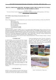
Figure 3: Results from automatic closing of large lacunas using the Rapid-<br />
Form2004 software.<br />
ic, manual or combined procedures. The filling of simple and<br />
small dimensions holes were conducted automatically, while<br />
for the complex and large lacunas the procedure was performed<br />
with the semi-automatic modality. The automatic procedure,<br />
applied in correspondence of the back of the wooden<br />
horse, carried out unsatisfactory results (Figure 3): the obtained<br />
surface is characterized by non adequate continuity<br />
with the adjacent surfaces and some topological anomalies<br />
are evident.<br />
The semi-automatic procedure allows to close the large<br />
lacunas (Figure 4a) respecting the topology of the adiacent<br />
surfaces. At first, a carrying skeleton has been created (Figure<br />
4b), taking in account the curved closing of the lacuna<br />
and, subsequently, the holes with small dimensions have<br />
been closed automatically (Figure 5).<br />
Mesh and Nurbs Surfaces Generation<br />
The lacunas filling have provided a global 3D model; the polygonal<br />
mesh has been simplified reducing the faces number<br />
and preserving the surface shape. In fact, the flat areas not<br />
need a large amount of data and allow to construct a lighter<br />
model with low computational effort.<br />
Adopting a 10% mesh-reduction, an increased smoothing<br />
is observed; moreover, the comparison between the decimated<br />
mesh and the original mesh provides residuals lower of the<br />
instrumental precision. This mesh has been used to extract<br />
nurbs surfaces. The operation is needed because the mesh<br />
modification is a slow and laborious procedure which involves<br />
also thousands of triangular faces. Using nurbs surfaces, the<br />
procedure is easier dealing with single elements covering the<br />
object.<br />
The nurbs surfaces extraction has been performed using<br />
an automatic procedure from the polygonal mesh; subsequently,<br />
the number and the control points’ distribution have<br />
been adjusted (Figure 6).<br />
Cross Sections and Profiles Extraction<br />
The polygonal mesh has been used to extract cross sections by<br />
means of the intersection between the 3D model with horizontal<br />
or vertical planes in the local reference system adopted (Figure<br />
7). Moreover, the same approach allows to generate profiles, pro-<br />
Figure 4: The big lacuna<br />
(a) on the back<br />
of the wooden horse<br />
was artificially subdivided<br />
in smaller lacunas<br />
(b) using a transversal<br />
skeleton structure.<br />
Figure 5: a) Construction<br />
of the longitudinal<br />
carrying skeleton;<br />
b) automatic reconstruction<br />
of the<br />
new lacunas (small<br />
dimension).<br />
FIllIng lacunas In terrestrIal laser cannIng data: tHe “cavallo lIgneo” oF tHe “Palazzo della ragIone” (Padua, Italy)<br />
19