CIPA HERITAGE DOCUMENTATION - CIPA - Icomos
CIPA HERITAGE DOCUMENTATION - CIPA - Icomos
CIPA HERITAGE DOCUMENTATION - CIPA - Icomos

Create successful ePaper yourself
Turn your PDF publications into a flip-book with our unique Google optimized e-Paper software.
Technological Approach<br />
Photogrammetric rectification<br />
The most of the applications that create rectified images,<br />
coming from either conventional or metric cameras, are using<br />
the projective transformation equations to define the relation<br />
between the film or digital sensor plane and the recording<br />
plane of a building’s facade. In this case, the building’s facade<br />
is considered flat and the low relief (if present) is assumed to<br />
produce negligible deformation on the final rectified image.<br />
The observation-measurements of at least four ground control<br />
points (predefined and topographically measured) on the image<br />
will lead to a solution of the unknown parameters that is<br />
connecting every point of the facade onto its digital image.<br />
The rectified image is finally generated through a resampling<br />
process.<br />
The advantages of the method are:<br />
➧ Quality control. By using more than the four minimum control<br />
points and through the statistical analysis it is possible<br />
to estimate the mean error and standard deviation of the<br />
produced rectified image. Adjustment is providing the optimal<br />
solution of the rectified image.<br />
➧ The connection of every point on the rectified image to the<br />
local coordinate system is feasible. The local coordinate<br />
system is implemented with the use of a common Total Station<br />
used to define the control points’ location on the building’s<br />
facades.<br />
➧ It is a fast and easy process.<br />
➧ It is leading to a complete digitisation, if the rectified image<br />
is used properly in a CAD environment.<br />
In the case where it is not possible to measure ground<br />
control points on the building’s facade (due to the inability to<br />
access the building, or if the image has been created from an<br />
old photograph scanning) the definition of the vanishing points<br />
on the image, through the collection of parallel horizontal or<br />
vertical lines, can determine the position of the camera in relation<br />
to the building’s facade locus (Karras, 1992). A similar<br />
product as the rectified image is generated. However, it lacks<br />
the quality control provided from the typical digital rectification<br />
process since no redundant control point measurements<br />
exist. No adjustment is applicable and only a couple of distance<br />
measurements can be used to calculate the final rectified<br />
product. The measurements that are used are horizontal<br />
and vertical distances that provide the correct scale of the rectified<br />
image (Karras, 1992; Fangi, 2001).<br />
However, the advantages of the method are the same as in<br />
the previous case of a rectified image using ground control<br />
point measurements. Additionally:<br />
➧ No complicated measuring devices and topographic networks<br />
are necessary.<br />
➧ They provide a rectified image product in a very short time.<br />
However, the users of this photogrammetric procedure<br />
might not or do not want to have any knowledge of photogrammetric<br />
theory.<br />
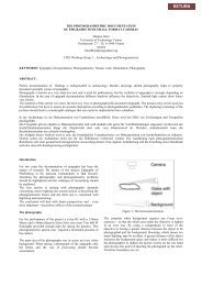
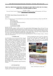
Figure 1: The rectified image was produced using control points measurements. In the lower right corner of the drawing space a magnifier window is displaying,<br />
in zoom, the region aground the cursor.<br />
50 <strong>CIPA</strong> <strong>HERITAGE</strong> <strong>DOCUMENTATION</strong> BEST PRACTICES AND APPLICATIONS Series I, 2007 & 2009