Example 4Moving Load No Propelling Force(W) WEIGHT(V) VELOCITYModel Selection: SALD 1-1/8 x 4STROKE(INCHES)W = 1,950 lbs.V = 5 ft./sec.F = 0C = 200/hr.E 1= .2WV² = .2 x 1,950 x 5² = 9,750 in-lbs.E 2= 0E 3= E 1+ E 2= 9,750 in.-lbsE 4= E 3x C = 9,750 x 200 = 1,950,000 in.-lbs./hr.WE = E 3/ [.2V²] = 1,950Example 5Moving Load With Propelling ForceCYLINDER: BORE DIA.PRESSURE(W) WEIGHT(V) VELOCITYModel Selection: SALD 1-1/8 x 2STROKE(INCHES)W = 1,950 lbs.V = 5 ft./sec.Cyl. Dia = 2 in.PSI = 80S = 2 in. *C = 100/hr.E 1= .2WV² = .2 x 1,950 x 5² = 9,750 in-lbs.F = Cyl. Force = .78 x D² x PSI = .78 x (2)² x 80 = 250 lbs.E 2= F x S = 250 x 2 = 500 in.-lbs.E 3= E 1+ E 2= 9,750 + 500 = 10,250 in.-lbs.E 4= E 3x C = 10,250 x 100 = 1,025,000 in.-lbs./hr.WE = E 3/ [.2V] = 10,250 / [.2(5)²] = 2,050 lbs.Example 6Moving Load Motor Driven(V) VELOCITY(W) WEIGHTModel Selection: SALD 1-1/8 x 2MOTOR RATING HPSTROKEW = 1,950 lbs.V = 5 ft./sec.HP= 1 HorsepowerS = 2 in. *C = 100/hr.E 1= .2WV² = .2 x 1,950 x 5² = 9,750 in-lbs.F = 1,375 x HP / [V] = 1,375 x 1 / [5] = 275 lbs.E 2= F x S = 550 in.-lbs.E 3= E 1+ E 2= 9,750 + 550 = 10,300 in.-lbsE 4= E 3x C = 10,300 x 100 = 1,030,000 in.-lbs./hr.WE = 10,300 / [.2V²] = 2,060 lbs.Example 7Moving Load Propelled by Drive Rollers (Chain/Belt Drive Conveyor)(W) WEIGHT(V) VELOCITYCOEFFICIENT OF FRICTIONSTROKEModel Selection: SALD 1-1/8 x 2*Note: These items will vary with individual applicationsand were selected for illustration purposes only.W = 1,950 lbs.V = 5 ft./sec.F = Coefficient of friction x WCoefficient of friction in thisexample = .18S = 2 in. *C = 100/hr.E 1= .2WV² = .2 x 1,950 x 5² = 9,750 in-lbs.E 2= F x S = (.18 x W) x 2 = 702 in.-lbs.E 3= E 1+ E 2= 9,750 + 702 = 10,452 in.-lbs.E 4= E 3x C = 10,452 x 100 = 1,045,200 in.-lbs./hr.WE = E 3/ [.2V] = 10,452 / [.2(5)²] = 2,090 lbs.Example 8Moving Load Down an Inclined Plane13(W) WEIGHTDISTANCE(INCHES)Model Selection: SALD 1½ x 2AºSTROKEW = 1,950 lbs.Angle of Incline = 15ºL = Distancetraveled= 30 in.S = 2 in. *C = 100/hr.23435 Industrial Park Dr., Farmington Hills, MI 48335 • p: 734-595-4500f: 734-595-6410 • customerservice@enertrols.com • www.enertrols.comE 1= W x Sin A x L = 1,950 x .26 x 30 = 15,210 in-lbs.E 2= W x Sin A x S = 1,950 x .26 x 2 = 1,014 in-lbs.E 3= E 1+ E 2= 15,210 + 1,014 = 16,224 in.-lbsE 4= E 3x C = 16,224 x 100 = 1,622,400 in.-lbs./hr.VS = √ 5.36 x (SinA) x L = √ 5.36 x .26 x 30 = 6.4 ft./sec.WE = E 3/ [.2VS²] = 16,224 / [.2(6.4)²] = 1980 lbs.
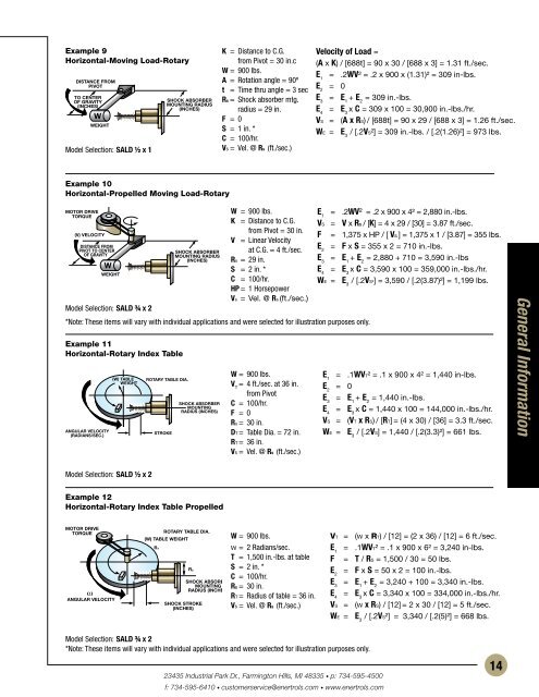
Example 9Horizontal-Moving Load-RotaryDISTANCE FROMPIVOTTO CENTEROF GRAVITY(INCHES)WEIGHTModel Selection: SALD ½ x 1SHOCK ABSORBERMOUNTING RADIUS(INCHES)K = Distance to C.G.from Pivot = 30 in.cW = 900 lbs.A = Rotation angle = 90ºt = Time thru angle = 3 secRs = Shock absorber mtg.radius = 29 in.F = 0S = 1 in. *C = 100/hr.Vs = Vel. @ Rs (ft./sec.)Velocity of Load =(A x K) / [688t] = 90 x 30 / [688 x 3] = 1.31 ft./sec.E 1= .2WV² = .2 x 900 x (1.31)² = 309 in-lbs.E 2= 0E 3= E 1+ E 2= 309 in.-lbs.E 4= E 3x C = 309 x 100 = 30,900 in.-lbs./hr.VS = (A x RS) / [688t] = 90 x 29 / [688 x 3] = 1.26 ft./sec.WE = E 3/ [.2VS²] = 309 in.-lbs. / [.2(1.26)²] = 973 lbs.Example 10Horizontal-Propelled Moving Load-RotaryMOTOR DRIVEW = 900 lbs.E 1= .2WV² = .2 x 900 x 4² = 2,880 in.-lbs.TORQUEK = Distance to C.G.VS = V x Rs / [K] = 4 x 29 / [30] = 3.87 ft./sec.from Pivot = 30 in.(V) VELOCITYF = 1,375 x HP / [ Vs ] = 1,375 x 1 / [3.87] = 355 lbs.V = Linear VelocityDISTANCE FROME 2= F x S = 355 x 2 = 710 in.-lbs.PIVOT TO CENTERSHOCK ABSORBER at C.G. = 4 ft./sec.OF GRAVITYMOUNTING RADIUS(INCHES) Rs = 29 in.E 3= E 1+ E 2= 2,880 + 710 = 3,590 in.-lbsS = 2 in. *E 4= E 3x C = 3,590 x 100 = 359,000 in.-lbs./hr.WEIGHTC = 100/hr.WE = E 3/ [.2VS²] = 3,590 / [.2(3.87)²] = 1,199 lbs.HP = 1 HorsepowerVs = Vel. @ Rs (ft./sec.)Model Selection: SALD ¾ x 2*Note: These items will vary with individual applications and were selected for illustration purposes only.Example 11Horizontal-Rotary Index TableANGULAR VELOCITY(RADIANS/SEC.)(W) TABLEWEIGHTROTARY TABLE DIA.STROKESHOCK ABSORBERMOUNTINGRADIUS (INCHES)W = 900 lbs.V T= 4 ft./sec. at 36 in.from PivotC = 100/hr.F = 0Rs = 30 in.DT = Table Dia. = 72 in.RT = 36 in.Vs = Vel. @ Rs (ft./sec.)E 1= .1WVT² = .1 x 900 x 4² = 1,440 in-lbs.E 2= 0E 3= E 1+ E 2= 1,440 in.-lbs.E 4= E 3x C = 1,440 x 100 = 144,000 in.-lbs./hr.VS = (VT x RS) / [RT] = (4 x 30) / [36] = 3.3 ft./sec.WE = E 3/ [.2VS] = 1,440 / [.2(3.3)²] = 661 lbs.General InformationModel Selection: SALD ½ x 2Example 12Horizontal-Rotary Index Table PropelledMOTOR DRIVETORQUEωANGULAR VELOCITYROTARY TABLE DIA.(W) TABLE WEIGHTRTRSSHOCK STROKE(INCHES)SHOCK ABSORBERMOUNTINGRADIUS (INCHES)W = 900 lbs.w = 2 Radians/sec.T = 1,500 in.-lbs. at tableS = 2 in. *C = 100/hr.Rs = 30 in.RT = Radius of table = 36 in.Vs = Vel. @ Rs (ft./sec.)VT = (w x RT) / [12] = (2 x 36) / [12] = 6 ft./sec.E 1= .1WVT² = .1 x 900 x 6² = 3,240 in-lbs.F = T / RS = 1,500 / 30 = 50 lbs.E 2= F x S = 50 x 2 = 100 in.-lbs.E 3= E 1+ E 2= 3,240 + 100 = 3,340 in.-lbs.E 4= E 3x C = 3,340 x 100 = 334,000 in.-lbs./hr.VS = (w x RS) / [12] = 2 x 30 / [12] = 5 ft./sec.WE = E 3/ [.2VS²] = 3,340 / [.2(5)²] = 668 lbs.Model Selection: SALD ¾ x 2*Note: These items will vary with individual applications and were selected for illustration purposes only.23435 Industrial Park Dr., Farmington Hills, MI 48335 • p: 734-595-4500f: 734-595-6410 • customerservice@enertrols.com • www.enertrols.com14
- Page 3: Any mechanism that moves and that m
- Page 8 and 9: Construction & Design FeaturesMinia
- Page 10 and 11: Standard Shock AbsorbersGold Line
- Page 12 and 13: Accessories & Special Application S
- Page 14 and 15: Selecting the Correct Type of Shock
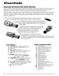
- Page 16: Selecting the Correct Size Shock Ab
- Page 21 and 22: Example 16Vertical-Rotating Beam Dr
- Page 23 and 24: Example 22Vertical Rotating Arm - C
- Page 25 and 26: Model Rating ChartsShock Absorber S
- Page 27 and 28: Self-Compensating ECA ModelsModel N
- Page 29 and 30: Construction and Parts Descriptions
- Page 31 and 32: Installation Recommendations and Ti
- Page 33 and 34: Additional Enertrols ProductsShock
- Page 35 and 36: SM 9 to SM 75MFSub-Miniature Shock
- Page 37 and 38: SNALD 150 to 600Miniature Shock Abs
- Page 39 and 40: SNALD 1/2 Bore x 1, 2"Miniature Sho
- Page 41 and 42: SA 30 to 150 & 1/4" BoreMiniature S
- Page 43 and 44: SALD 3/8 Bore x 1"Miniature Shock A
- Page 45 and 46: SALD 1/2 Bore x 1, 2"Miniature Shoc
- Page 47 and 48: Industrial Shock AbsorbersWeartec P
- Page 49 and 50: SNALD 33, 45 & 64 SeriesOrdering In
- Page 51 and 52: SNALD 33 SeriesMid-Size Shock Absor
- Page 53 and 54: SNALD 45 SeriesMid-Size Shock Absor
- Page 55 and 56: SNALD 64 SeriesMid-Size Shock Absor
- Page 57 and 58: AccessoriesSNALD Mid-Size 33, 45 &
- Page 59 and 60: SALD ½ x 1, 2-P, SALD ¾ x 1, 2, 3
- Page 61 and 62: Gold Line ® & Silverline ® Primar
- Page 63 and 64: Retention Kit for MSC Installations
- Page 65 and 66: SALD 3/4, 1-1/8,1-1/2, 2-1/4Gold Li
- Page 67 and 68:
Positive Stop Collar (-PSC) for Fix
- Page 69 and 70:
SILVERLINE ® SeriesDimensions in i
- Page 71 and 72:
High Precision Metric (HPM) Series
- Page 73 and 74:
EA 2 to EA3Heavy Industrial Shock A
- Page 75 and 76:
ECA and EA 2", 3" Bore SeriesECA Se
- Page 77 and 78:
ECA and EA 2", 3" Bore SeriesECA Se
- Page 79 and 80:
ECA 4" Bore SeriesHeavy Duty Models
- Page 81 and 82:
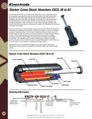
Stacker Crane Shock Absorbers ESCS-
- Page 83 and 84:
Stacker Crane Shock Absorbers ESCS-
- Page 85 and 86:
Industrial Crane Bumper Shocks ECB-
- Page 87 and 88:
Industrial Crane Bumper Shocks ECB-
- Page 89 and 90:
Dimensions in inches and (mm)ABCD0.
- Page 91 and 92:
AR0.27(R7)BC0.32(8.1)0.55(14)M8 x 1
- Page 93 and 94:
Mounting Brackets for Hydraulic Dam
- Page 95 and 96:
EDVC Velocity & Feed ControllersC51
- Page 97 and 98:
EVC Velocity & Feed Controllers wit
- Page 99:
Stocking DistributorsUSA, Canada an