SILVERLINE ® Series Specifications3/4, 1-1/8, 1-1/2,2-1/4 BoreSILVERLINE ® SpecificationsEnergy per HourWe E 3E 4SASLModelStrokein.Effective WeightMin/Maxlbs (kg)Max. Energy/Cyclein lbs (Nm)Internal Accumulatorin. lbs (Nm)External Accumulatorin. lbs (Nm)Mounting Strength2.5 x E3 (Max)Strokelbs (N)SASL 3/4x1 1300-260,000(136-117,936)3,000(339)1,100,000(124,284)1,600,000(180,776)7,500(33,300)SASL 3/4x2 2350-500,000(159-226,800)6,000(678)1,300,000(146,881)2,000,000(225,970)7,500(33,300)SASL 1-1/8x1 1700-700,000(318-317,520)8,000(904)1,250,000(141,231)2,500,000(282,463)20,000(89,000)SASL 1-1/8x2 2850-1,300,000(386-589,680)16,000(1,808)1,500,000(169,478)3,000,000(338,955)20,000(89,000)*SASL 1-1/2x2 222,000-1,360,000(9979-616,896)21,000(2,373)3,200,000(361,552)4,000,000(451,940)26,250(117,000)*SASL 2-1/4x2 250,000-3,175,000(22,680-1,440,180)56,000(6,327)16,000,000(1,807,760)20,000,000(2,259,700)32,500(144,600)*Special order, check availabilityOrdering InformationSASL 3/4 x 1 P - SFReturn Method and Accumulator StyleSASL = Internal Accumulator, Spring ReturnASLA = Internal Accumulator, Mechanical ReturnASLS = External Accumulator, Spring ReturnASL = External Accumulator, Air or Mech. ReturnBore Size Stroke Series3/41-1/81-1/22-1/412Fixed FlangeP-PrimaryMounting Style & OptionsPrimary, 3/4 & 1-1/8Basic Mounting Threads and one Jam Nut-SF Square Flange-RF Rectangle Flange - (not available 1-1/8 bore)-L Side-Foot Mount-C Clevis Mount-Z Blind-end Air Cylinder Mounting-SP Poly Pad except with -PSC, -MSC, -FSC, -C, or -Z-PSC Positive Stop Collar - for Basic or Rear Mount Only-FSC Flanged Stop Collar - for Basic Mount Only-MSC Mounting Stop Collar - for Basic Mount OnlyFixed Flange 3/4 to 2-1/4-F Square Front Flange (1-1/8, 1-1/2, 2-1/4 bore)-R Square Rear Flange (1-1/8, 1-1/2, 2-1/4 bore)-RF Rectangle Front Flange - (3/4, 1-1/2 bore)-RR Rectangle Rear Flange - (3/4, 1-1/2 bore)-L Side-Foot Mount (1-1/2, 2-1/4 bore)-C Clevis Mount-SP Poly Pad except with 2-1/4 bore, -PSC, -PSB, -C, or -Z-PSC Positive Stop Collar - for Rear Flange Mount Only-PSB Positive Stop Bars - for Front Flange Mount OnlyTechnical DataImpact velocity range: 0.25 to 2 ft/sec (0.076 to 0.61 m/sec)Operating temperature: 10º to 150º F (-12º to 66º C)Oil type: ISO 46 AWMaterials: Steel body, hardened steel piston rod.65<strong>Enertrols</strong> recommends that you select a model with 20% more capacity thanyour calculations indicate necessary. This extra capacity allows for changesif weight, velocity, or cycle rates should increase in <strong>the</strong> future.For velocities out of range, consult factory.23435 Industrial Park Dr., Farmington Hills, MI 48335 • p: 734-595-4500f: 734-595-6410 • customerservice@enertrols.com • www.enertrols.com
High Precision Metric (HPM) Series Fixed Flange - 19 mm Bore Mounting12DAC ±0519 DIAB7660*2919 DIAADJUSTERAC ±05 B 766038 54DIA DIA40 5738DIA40 57Rear FlangeBore Model A (mm) B (mm) C (mm) D (mm)19HPSL** - 3000 RRM PSC 144 24 120 35HPSL** - 6000 RRM PSC 195 50 145 47HP - 3000 RRM PSC 144 24 120 35HP - 6000 RRM PSC 195 50 145 47HP - 9000 RRM PSC 246 75 171 60**SILVERLINE models for low-velocity applicationsHigh Precision Metric (HPM) Series Fixed Flange - 28mm Bore Mounting45 DIABore Model A (mm) B (mm) C (mm) D (mm)199.0 DIA-THRU(4) MTG. HOLESIN FLANGEFront FlangeD12 FLANGETHICKNESS*(54 MM BODY CLEARANCE HOLE DIA. REQUIREDIN MOUNTING STRUCTURE)HPSL** - 3000 RFM PSB 144 24 38 35HPSL** - 6000 RFM PSB 195 50 38 47HP - 3000 RFM PSB 144 24 38 35HP - 6000 RFM PSB 195 50 38 47HP - 9000 RFM PSB 246 75 38 6615Bore Model A (mm) B (mm) C (mm) D (mm)28HPSL** - 8000 RM PSC 175 24 150 42HPSL** - 16000 RM PSC 225 50 175 55HP - 16000 RM PSC 225 50 175 55HP - 32000 RM PSC 327 101 226 80Energy Capacity RatingsBore Stroke Model No.1928DRear FlangeAC ±0519 DIA1" HPSL** - 30002" HPSL** - 60001" HP 30002" HP 60003" HP 90001" HPSL** - 80002" HPSL** - 160002" HP 160004" HP 32000B51 79DIA DIA**SILVERLINE models for low-velocity applications(We) Effective Weight (min/max)lbs. (kg)300-260,000(136-117,936)350-500,000(159-226,800)20-18,000(9-8,165)89 SQ70 SQ35-32,000(16-14,515)50-46,000(23-20,866)700-700,000(227-317,520)850-1,300,000(386-589,680)120-50,000(54-22,680)100-100,000(73-45,360)*3867 DIABore Model A (mm) B (mm) C (mm) D (mm)28Max. Capacityin lbs/cycle (Nm/cycle)3,000(339)6,000(678)3,000(339)6,000(678)9,000(1,017)8,000(791)16,000(1,582)16,000(1,582)32,000(3,164)19 DIA11.0 MM DIA-THRU(4) MTG HOLES INMOUNTING FLANGEFront FlangeAADJUSTER C ±05 B 89 SQD15 FLANGETHICKNESS*(79.4 MM BODY CLEARANCE HOLE DIA.REQUIRED IN MOUNTING STRUCTURE)51DIA70 SQHPSL** - 8000 FM PSB 175 24 51 42HPSL** - 16000 FM PSB 225 50 51 55HP - 16000 FM PSB 225 50 51 55HP - 32000 FM PSB 327 101 51 80Industrial Shock AbsorbersPositive Stop Collars for Fixed Flange, Rear Mounted ShockAbsorbers 19 mm - 28 mm Bore Size HPM SeriesPositive Stop Bars for Fixed Flange, Front Mounted ShockAbsorbers 19 mm - 28 mm Bore Size HPM Series23435 Industrial Park Dr., Farmington Hills, MI 48335 • p: 734-595-4500f: 734-595-6410 • customerservice@enertrols.com • www.enertrols.comBore Part Number19 3137-3451428 3142-34514Bore Part Number19 3137-3451628 3142-3451666
- Page 3:
Any mechanism that moves and that m
- Page 8 and 9:
Construction & Design FeaturesMinia
- Page 10 and 11:
Standard Shock AbsorbersGold Line
- Page 12 and 13:
Accessories & Special Application S
- Page 14 and 15:
Selecting the Correct Type of Shock
- Page 16:
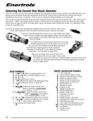
Selecting the Correct Size Shock Ab
- Page 19 and 20: Example 9Horizontal-Moving Load-Rot
- Page 21 and 22: Example 16Vertical-Rotating Beam Dr
- Page 23 and 24: Example 22Vertical Rotating Arm - C
- Page 25 and 26: Model Rating ChartsShock Absorber S
- Page 27 and 28: Self-Compensating ECA ModelsModel N
- Page 29 and 30: Construction and Parts Descriptions
- Page 31 and 32: Installation Recommendations and Ti
- Page 33 and 34: Additional Enertrols ProductsShock
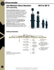
- Page 35 and 36: SM 9 to SM 75MFSub-Miniature Shock
- Page 37 and 38: SNALD 150 to 600Miniature Shock Abs
- Page 39 and 40: SNALD 1/2 Bore x 1, 2"Miniature Sho
- Page 41 and 42: SA 30 to 150 & 1/4" BoreMiniature S
- Page 43 and 44: SALD 3/8 Bore x 1"Miniature Shock A
- Page 45 and 46: SALD 1/2 Bore x 1, 2"Miniature Shoc
- Page 47 and 48: Industrial Shock AbsorbersWeartec P
- Page 49 and 50: SNALD 33, 45 & 64 SeriesOrdering In
- Page 51 and 52: SNALD 33 SeriesMid-Size Shock Absor
- Page 53 and 54: SNALD 45 SeriesMid-Size Shock Absor
- Page 55 and 56: SNALD 64 SeriesMid-Size Shock Absor
- Page 57 and 58: AccessoriesSNALD Mid-Size 33, 45 &
- Page 59 and 60: SALD ½ x 1, 2-P, SALD ¾ x 1, 2, 3
- Page 61 and 62: Gold Line ® & Silverline ® Primar
- Page 63 and 64: Retention Kit for MSC Installations
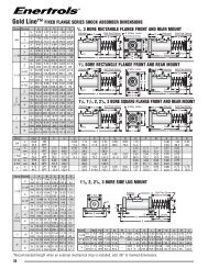
- Page 65 and 66: SALD 3/4, 1-1/8,1-1/2, 2-1/4Gold Li
- Page 67 and 68: Positive Stop Collar (-PSC) for Fix
- Page 69: SILVERLINE ® SeriesDimensions in i
- Page 73 and 74: EA 2 to EA3Heavy Industrial Shock A
- Page 75 and 76: ECA and EA 2", 3" Bore SeriesECA Se
- Page 77 and 78: ECA and EA 2", 3" Bore SeriesECA Se
- Page 79 and 80: ECA 4" Bore SeriesHeavy Duty Models
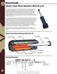
- Page 81 and 82: Stacker Crane Shock Absorbers ESCS-
- Page 83 and 84: Stacker Crane Shock Absorbers ESCS-
- Page 85 and 86: Industrial Crane Bumper Shocks ECB-
- Page 87 and 88: Industrial Crane Bumper Shocks ECB-
- Page 89 and 90: Dimensions in inches and (mm)ABCD0.
- Page 91 and 92: AR0.27(R7)BC0.32(8.1)0.55(14)M8 x 1
- Page 93 and 94: Mounting Brackets for Hydraulic Dam
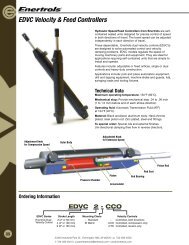
- Page 95 and 96: EDVC Velocity & Feed ControllersC51
- Page 97 and 98: EVC Velocity & Feed Controllers wit
- Page 99: Stocking DistributorsUSA, Canada an