View the Enertrols Main Catalog featuring industrial shock ...
View the Enertrols Main Catalog featuring industrial shock ...
View the Enertrols Main Catalog featuring industrial shock ...

You also want an ePaper? Increase the reach of your titles
YUMPU automatically turns print PDFs into web optimized ePapers that Google loves.
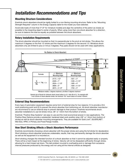
Installation Recommendations and TipsMounting Structure Considerations<strong>Enertrols</strong> <strong>shock</strong> absorbers should be rigidly bolted to a non-flexing mounting structure. Refer to <strong>the</strong> "MountingStrength Required" column in <strong>the</strong> Energy Capacity table for <strong>the</strong> model you have selected.Avoid side loads of more than 5º (3º for miniature models) and align <strong>the</strong> centerline of <strong>the</strong> piston as closely aspossible to <strong>the</strong> impacting object's center of gravity. When using more than one <strong>shock</strong> absorber for a direction,be sure to balance <strong>the</strong> load as equally as possible between <strong>the</strong> <strong>shock</strong> absorbers.Rotary Installation RequirementsThe <strong>shock</strong> absorber should be mounted so that it is perpendicular to <strong>the</strong> pivot at mid stroke. This allows <strong>the</strong>maximum 5 degrees on <strong>the</strong> first 1/2 stroke and <strong>the</strong> maximum 5 degrees for <strong>the</strong> second 1/2. Miniature <strong>shock</strong>absorbers only are limited to plus or minus 3 degrees. Poly pads should not be used with rotary applications.Rs (Radius to Shock Absorber)Plus 5 degrees Maximum at ImpactPerpendicularat Mid-StrokeMinus 5 degrees Maximum at Set-DownaaStrokeFormulaS < *No. = aRsExternal Stop Recommendations+/- MaximumMounting Angle.0175 = 1/2º.0349 = 1º.0524 = 1-1/2º.0699 = 2º.0875 = 2-1/2º+/- MaximumMounting Angle.1051 = 3º.1228 = 3-1/2º.1405 = 4º.1584 = 4-1/2º.1763 = 5º*Miniature models; 3 degrees maximum, all o<strong>the</strong>rs 5 degrees maximumGeneral rule of thumb for minimum <strong>shock</strong> mount radius is a 6:1 ratio (Rs to S). For example with1 inch (25mm) of <strong>shock</strong> absorber stroke, <strong>the</strong> minimum “Rs” mount radius is 6 inches (150mm).Every type of automation equipment requires some form of external stop for two reasons; (1) to provide a firmwork positioning point and (2) to prevent <strong>the</strong> <strong>shock</strong> absorber from bottoming out. All <strong>shock</strong> absorber manufacturersrecommend to use an external stop to prevent damage to <strong>the</strong>ir product. <strong>Enertrols</strong> recommends <strong>shock</strong>absorber installations to use full stroke minus .06" or 1.6mm from <strong>the</strong> bottom of stroke.<strong>Enertrols</strong> "Positive Stop Systems" are easy to use and <strong>the</strong> most economical answer in new applications. ThePositive Stop Options provide a substantial, hardened steel work position stop (.06" or 1.6mm from bottom ofstroke) as well as <strong>shock</strong> absorber mounting arrangements. They are available for Gold Line ® , SILVERLINE ® ,Mid-Size, HPM, in Primary and Fixed Flange models.General InformationHow Short Stroking Affects a Shock Absorbers Performance<strong>Enertrols</strong> recommends choosing a <strong>shock</strong> absorber with <strong>the</strong> proper stroke and using <strong>the</strong> full stroke for deceleration.Short stroking a <strong>shock</strong> absorber produces undesirable, results, that may permanently damage <strong>the</strong> <strong>shock</strong> absorberas well as <strong>the</strong> equipment it is mounted on.Short stroking changes <strong>the</strong> intended function of a <strong>shock</strong> absorber so that it cannot be adjusted easily or properly.There will be a hard impact at <strong>the</strong> beginning of stroke. Velocity will not be dissipated sufficiently through stroke,allowing for a hard impact set down. The last problem incurred is overheating and or damage from excessiveinternal pressures produced by <strong>the</strong> energy and not using all <strong>the</strong> internal orifices as designed.23435 Industrial Park Dr., Farmington Hills, MI 48335 • p: 734-595-4500f: 734-595-6410 • customerservice@enertrols.com • www.enertrols.com26