
Create successful ePaper yourself
Turn your PDF publications into a flip-book with our unique Google optimized e-Paper software.
Table of ContentsIntroduction 1<strong>Wood</strong> Codes & Materials 2Creating <strong>Wall</strong> Geometry 3Headers 7Assigning Design Parameter Regions 8<strong>Wall</strong> Design Rules 9Loading 12Designing the <strong>Wall</strong>: Segmented Design Method 14Segmented Results 17<strong>Wall</strong> Summary Detail Report 19Regions In-Plane Detail Report 21Designing the <strong>Wall</strong>: Perforated Design Method 23Perforated Results 24Perforated <strong>Wall</strong> Summary Detail Report 25Perforated Header Detail Report 27Designing the <strong>Wall</strong>: Force Transfer Design Method 28Force Transfer Results 31Force Transfer Summary Detail Report 32Force Transfer Header Detail Report 34Conclusion 35
RISA-3D <strong>Wood</strong> <strong>Panel</strong> <strong>Tutorial</strong>IntroductionThis hands-on guide will help introduce you to the RISA <strong>Wood</strong> <strong>Wall</strong> <strong>Panel</strong>, and walk you through an start-to-finishexample with helpful information along the way. This is intended for both experienced and first-time users of RISA-3D.All the action items in this guide are indicated with bullets shown below:• Action ItemThis guide is intended to show you the basics of the wall panel feature. If you have further questions beyond this guide,please refer to the RISA-3D General Reference and the online help file.Note: If you are not familiar with RISA-3D, you should also complete the tutorials in the RISA-3D User’s Guide available onthe RISA web site at www.risatech.comThe RISA-3D <strong>Wood</strong> <strong>Panel</strong> <strong>Tutorial</strong> is compatible with RISA-3D 10 or higher.1
RISA-3D <strong>Wood</strong> <strong>Panel</strong> <strong>Tutorial</strong><strong>Wood</strong> Codes & MaterialsLet’s start by setting the design code:• Click on the Global Parameters icon.• Choose the Codes tab.• Select the <strong>Wood</strong> code from the drop down list: AF & PA NDS-05/08:ASD.• Click OK.<strong>Wood</strong> Design Codes available in RISA:• NDS 2008: ASD• NDS 2005: ASD• NDS 2001: ASD• NDS 1997: ASDThe wood species available can be found byclicking in the Species column, and clickingon the dropdown arrow. The list is organizedwith all the species available in the NDSfirst, and the Glulam types at the bottom. Ifyou add your own Custom Material Species,you will find your new species name locatedbetween the NDS wood species and theglulam types.You can create your own Custom <strong>Wood</strong>Species by going to the Spreadsheet Menuand selecting Custom <strong>Wood</strong> Species.Let’s create the material for the wood wall:• Click on the Materials button on the Data Entry Toolbar:(If you don’t see your Data Entry Toolbar, click on theIcon).• Click on the <strong>Wood</strong> tab at the top of the dialog box.• We’ll use DF/SPine.• Click to close the spreadsheet.TIP: RISA-3D has a variety of defaultmaterial properties available; you can saveyour own default materials available bypressing the default icon at the top of thescreen when the Materials spreadsheet isopen.NOTE: If you don’t see the DF/SPine labelin your <strong>Wood</strong> Materials spreadsheet, youmay use the available wood species or go toTools > Reset All Program Defaults to get allthe wood species defaults for Version 10or higher.2
RISA-3D <strong>Wood</strong> <strong>Panel</strong> <strong>Tutorial</strong>Using the drawing grid to create a 10’ high rectangular wall:• Click on the bottom left corner (0,0,0),• Move your cursor to 10’ height and left click on (0,10,0),• Move the cursor to the top right corner and left click on (16,10,0),• Left click on the last point (16,0,0).The Drawing Grid will help you draw thewall. As the cursor hovers over the drawinggrid intersection lines, a red star will appearwhich indicates where the joint will belocated. If your drawing grid is not visible,click the icon.• Right-click the mouse or press Esc to stop drawing.Notice that you can view the cursorcoordinates in the lower right portion ofthe screen to help view the location of thenodes.The wall panel will be created after the fourth click of the mouse and shouldlook like the picture above.Let’s change the Units to inches:• Click on the Unit icon.• Under Lengths, click on the dropdown menu and select inches.• Click OK.4
RISA-3D <strong>Wood</strong> <strong>Panel</strong> <strong>Tutorial</strong>Let’s open the <strong>Wall</strong> <strong>Panel</strong> Editor:• Double click on the <strong>Wall</strong> <strong>Panel</strong> to view the <strong>Wall</strong> <strong>Panel</strong> Editor:The drawing grid in the <strong>Wall</strong> <strong>Panel</strong> Editor is atool that guides your placement of openings,holddowns, straps and boundary conditions.The grid is independent of your model, soyou may change the grid as you build themodel without changing any modeling.Note: In the Drawing Grid, you may usesymbols such as:Let’s change the drawing grid to locate the openings:• In the Draw Toolbox, click in the box next to the Grid Increments H(Horizontal), clear the current entry and type 40, 32, 3@40.• In the Draw Toolbox, click in the box next to the Grid Increments V(Vertical), clear the current entry and type 3@40.“@” (to specify multiple, equally spacedincrements).“/” (to subdivide a larger increment intosmaller increments).“,” (to enter multiple increments in theincrement field).• Press the Tab key.The grid will automatically resize to adjust to the new scale. You can alsotoggle the grid display on and off by clicking the icon.5
RISA-3D <strong>Wood</strong> <strong>Panel</strong> <strong>Tutorial</strong>We’ll create a window and a door opening:• Your mouse should automatically be changed Create NewOpenings icon. If not, click on the Create New Openings icon atthe top left of the <strong>Wall</strong> <strong>Panel</strong> Editor to create an opening.Let’s create the door opening:• Using the coordinates at the bottom right corner, left click on thebottom left corner of the opening (40,0,0).<strong>Wall</strong> <strong>Panel</strong>s can have rectangular openings.You can click on any location on the grid tocreate an opening.Openings can be created anywhere on thewall panel except the upper and side edges.Note: If you make a mistake, you can deletean opening by using the Delete tool.• Move the mouse to the top right corner (72,80,0) and left click on thegrid intersection.Now let’s create a window opening:• Left click on the bottom left corner (112,40,0),• Move the mouse to the top right corner (152,80,0) and left click on thegrid intersection.• Right click to escape.6
HeadersLet’s review the header design parameters:• Double left click directly inside the window opening to view theheader design parameters.• If the headers do not show, use the toggle icon to turn them on.Here we will walk through the different input options available for designing/analyzing headers.RISA-3D <strong>Wood</strong> <strong>Panel</strong> <strong>Tutorial</strong>Headers will automatically be created andplaced above the openings in wood walls.Within this window you must specify designoptions to design/analyze your header. Thetrimmers are input as well but only for thematerial take off.Each header can be designed separatelywith different parameters or you can chooseto match the properties of another Header.Assign the header design parameters:• Select <strong>Wall</strong> Design Rule: Typical.The header selection is based off the rule assigned in the <strong>Wall</strong> <strong>Panel</strong>Design Rules or you can click the button to assign the Header size andMaterial directly.• Click OK.We will review the header Design Rule in the next session.7
RISA-3D <strong>Wood</strong> <strong>Panel</strong> <strong>Tutorial</strong>Assigning Design ParameterRegionsLet’s define Regions inside the wall for design/ analysis of thewood shear wall:• Select the Generate <strong>Wall</strong> Regions Automatically icon.What is a Region?In RISA, we define a wall strip for design asa Region. In reference codes this is referredto as a full height wall segment or pier.Regions must be rectangular. To createthem, use the cursor to select two nodes orgrid intersections which define the lower leftcorner and upper right corner of the region.Note: Regions cannot overlap openings.RISA automatically creates a region forwalls. However, you can also manuallycreate Regions by selecting the Create NewRegions iconIn order to get a design a Segmented wall,a region must be defined for every piece ofthe wall.The wall drawing should now look like the picture above.• Click OK to exit the <strong>Wall</strong> <strong>Panel</strong> Editor<strong>Wall</strong> <strong>Panel</strong> ViewYou can use the <strong>Wood</strong> View Controls to Toggle the display of the <strong>Wall</strong> Studs, Chords , and Sill Plates after solution.8
<strong>Wall</strong> Design RulesRISA-3D <strong>Wood</strong> <strong>Panel</strong> <strong>Tutorial</strong>Let’s review the <strong>Wall</strong> <strong>Panel</strong> parameters in the Design Rulesspreadsheets.• Open the <strong>Wall</strong> Design Rules spreadsheet from the Data Entry toolbar,and click on the <strong>Wood</strong> <strong>Wall</strong> (Studs) tab.(If you don’t see your Data Entry toolbar, click on the Icon).• Top Plate: Select 2-2X6:Click on the red arrowSelect Thick/Diameter: 2Select Width: 6Select Multiple Plies: 2within the Top Plate column.Stud design is accomplished by taking theentire axial load in the wall and dividingit by the number of studs. The spacing isoptimized based on the range in the DesignRules (Studs) spreadsheet.Optimizing the <strong>Wall</strong> <strong>Panel</strong>sRISA will design and optimize the wallpanels based on the criteria in the <strong>Wall</strong><strong>Panel</strong> Design Rules. There is a setting in theGlobal Parameters Solution tab thatwill set the wall to optimize upon solution. Ifyou want to check an existing wall, you canexplicitly select the wall panel size and makesure to turn off the wall optimization.• Sill Plate: Select 2X6• Studs: Select 2X6• Min Stud Spacing: 16• Max Stud Spacing: 24• Green Lumber: Unchecked• Header Size: Select 2 - 2X69
RISA-3D <strong>Wood</strong> <strong>Panel</strong> <strong>Tutorial</strong>• Header Material: Same As <strong>Wall</strong>.• Click on the <strong>Wood</strong> <strong>Wall</strong> (Fasteners) tab.• Schedule: Click on the red arrow within the Schedule columnSelect IBC-06-09 <strong>Panel</strong> Database and make sure Select Entire <strong>Panel</strong>Group is selected.Click OK.The <strong>Wood</strong> <strong>Wall</strong> <strong>Panel</strong> Schedule and HoldDown Schedule are based on an XML filedatabase.The <strong>Wood</strong> <strong>Wall</strong> <strong>Panel</strong> Schedule database isspecified by an XML file in the Shear <strong>Panel</strong>sfolder, a sub-directory of the RISA_<strong>Wood</strong>_Schedules folder located in the C:\RISAfolder. (This defaults into the C:\RISA folder,but you can also find the directory locationby going to Tools>Menu>Preferences>FileLocations.)Min <strong>Panel</strong> Spacing: Type 0.3125Max <strong>Panel</strong> Spacing: Type 0.375Double Sided <strong>Panel</strong>?: Select OptimumMax. Nail Spacing: Select 6-inMin. Nail Spacing: Select 3-inHD Chords: Select 2-2x6HD Chords Matl: Same as <strong>Wall</strong>Hold Down: Select HDU_DFClick on the red arrow within the Schedule columnSelect Simpson_HDU from the Select Manufacturer dropdownThe Hold Down Schedule database isspecified by an XML file in the HoldDownsfolder, a sub-directory of the RISA_<strong>Wood</strong>_Schedules folder.The wall panel design is optimized basedon the shear capacity. The shear demandis determined for the wall, and the panel ischosen with the closest shear capacity.You can select an entire series or list ofpanels, or select one panel by clicking onthe Label.Select HDU_DF in the Available HD Series list and make sure UseEntire Series is selected.Click OK.10
RISA-3D <strong>Wood</strong> <strong>Panel</strong> <strong>Tutorial</strong>You can modify these databases or createnew databases. For more information onthe formatting requirements, refer to theAppendix F <strong>Wood</strong> Shear <strong>Wall</strong> Files in theHelp Menu of RISA-3D.• Close the Design Rules spreadsheet.To better view the wall, click on the Rendered Iconto Isometric view tool .twice, and the SnapNote: To view the wall panel rendered to 100%, go to the Plot Optionsdialog, and click the <strong>Panel</strong>s tab and select 100% using the drop-down menu.11
RISA-3D <strong>Wood</strong> <strong>Panel</strong> <strong>Tutorial</strong>LoadingLet’s create the Basic Load Cases:• Open the Basic Load Case spreadsheet on the Data Entry toolbar orpress the icon.• Type Dead Load on the first line under the BLC Description column.• Select DL (Dead Load) from the Category drop-down menu.• Type -1 into the Y Gravity column.<strong>Wall</strong>s can be loaded with joint, surfaceloads, or distributed loads.You must define the Category in order to usethe Load Combination Generator.Typing a -1 in the Y Gravity column creates aBasic Load Case which includes self-weight.Let’s add wind load case:• Type Wind Load on the second line under the BLC Descriptioncolumn.• Select WL (Wind Load) from the Category drop-down menu.• Exit BLC Spreadsheet by clicking the on the top right corner.Add a distributed load to the wood wall:• Click on Distributed Load icon.• Select Y for Direction in the drop-down menu.• Type -0.10 as the Start Magnitude; End Magnitude will automaticallyfill in.• Select Basic Load Case 1: Dead Load.• Click Apply Load by Clicking Members/<strong>Wall</strong> <strong>Panel</strong> EdgesIndividually.• Press Apply.• Click on the top of the wall.• Right click to escape.12
RISA-3D <strong>Wood</strong> <strong>Panel</strong> <strong>Tutorial</strong>Let’s add a point load of wind load to this wall:• Click on Joint Load icon.Joint loads can only be applied in the globaldirections. We can tell that this is the globalaxis because the X is upper case.• Select This is a Load.• Select Direction: X from the dropdown list.• Type Magnitude: 2.• Select Basic Load Case 2: Wind Load.• Select Apply Load by Clicking/Boxing Joints.• Click Apply.• Click or box Node N2.13
RISA-3D <strong>Wood</strong> <strong>Panel</strong> <strong>Tutorial</strong>Designing the <strong>Wall</strong>: SegmentedDesign MethodThe LC Generator allows you to create loadcombinations quickly based on the code youselect.Let’s create the load combinations using the LC Generator:• Open the Load Combination spreadsheet by selecting the Icon atthe top of the screen.• Select LC Generator .• Select United States for the LC Region.• Select 2009 IBC ASD for the LC Code.• Uncheck RLL, SL, RL.• Click Generate• Click on Wind tab.14
RISA-3D <strong>Wood</strong> <strong>Panel</strong> <strong>Tutorial</strong>• Click the 2D Only button under Wind Load Options.• Check the Reversible option.• Click Generate.• Click Close.The Load Combination spreadsheet will automatically generate all the loadcombinations from the IBC 2009 and should look like the picture below• Close LC spreadsheet.Let’s review the loads as they are applied to the wall:• Toggle the loads display to On by clicking the icon if they’re notalready turned on.• The load display control panel is on the top of the screen.To display loads, we will work with theloading display toolbar at the top of thescreen.• Click on the toggle icon to switch to the Load Combinations LC.• Select the LC4 in the drop-down dialog15
RISA-3D <strong>Wood</strong> <strong>Panel</strong> <strong>Tutorial</strong>You should now see the Load Combination 4: IBC 16-12 (a) (a) displayed onyour screen as below.With all the loads applied, let’s run the analysis:• Click the Analysis and Design Icon.• Select the Batch Solution of Marked Combinations radio button.• Click Solve.A Single solution will only solve the selectedload combination. An Envelope solutionwill solve multiple load combinations andthe results will show only the maximumand minimum. The Batch solution will solvemultiple combinations and the results will beretained for every solution.The Detail Report is only available for SingleCombination solutions or Batch solutions.16
Reviewing results:Segmented Results• Select the <strong>Wall</strong> <strong>Panel</strong> Design spreadsheet from the Results toolbar.(If you don’t see your Results toolbar, click the icon).• To view the different results for wall panels click on the tabs at thetop: <strong>Wood</strong> <strong>Wall</strong> Axial, <strong>Wood</strong> <strong>Wall</strong> In-PlaneThe <strong>Wood</strong> <strong>Wall</strong> Axial results provide the code checks relevant to Axialloads of the wall.RISA-3D <strong>Wood</strong> <strong>Panel</strong> <strong>Tutorial</strong>Design MethodSegmented: A wall is broken up intoseparate full-height regions or segmentsand designed separately. If the shear wallhas openings, the area above and below theopenings are disregarded.Perforated: The total shear is applied tothe wall, and is divided by the width of thefull height sections of your wall. There aremany limitations as to when the PerforatedMethod can be applied, refer to the NDS2008, Special Design Provisions for Wind andSeismic 4.3.5.3.Force Transfer, FTAO: This method allowsyou to use the entire area of the wall minusthe openings to resist the shear in thewall. The framing around the openings isreinforced for this method.The <strong>Wall</strong> <strong>Panel</strong> Label and Region correspond to the wall panel labels andregions defined in the <strong>Wall</strong> <strong>Panel</strong> Editor.The Stud Size and Stud Spacing correspond to the studs selected andspacing range in the Design Rules.The Axial Check is a code check ratio between the member load and themember capacity. A value greater 1.0 for either of these values indicatesfailure. The Gov LC shows the load combination that governed for the codecheck.The Chord Size corresponds to the chord selected and spacing range in theDesign Rules. Note that the chords are the vertical hold down members/posts at both ends of every Region.The Chord Axial Check is a code check ratio between the member load andthe member capacity. A value greater 1.0 for either of these values indicatesfailure. The Gov LC shows the load combination that governed for the ratiomentioned above.Note: The chords are the vertical hold downmembers/posts at both ends of every Region.17
RISA-3D <strong>Wood</strong> <strong>Panel</strong> <strong>Tutorial</strong>The In-Plane results provide the code checks for the shear wall behavior ofthe wall.The Shear <strong>Panel</strong> Label describes the shear panels selected for the wall.The Shear Check is a code check ratio between the panel shear load andthe panel shear capacity. A value greater 1.0 for either of these valuesindicates failure. The Gov LC shows the load combination that governed forthe code check.The Hold-Down Label describes the hold down size selected for the wall.The Tension Check is a code check ratio between the tension load and thehold down provided capacity. A value greater 1.0 for either of these valuesindicates failure. The Gov LC shows the load combination that governed forthe ratio mentioned above.• Close the <strong>Wall</strong> <strong>Panel</strong> Design spreadsheet.Let’s take a closer look at the wall by viewing the Detail Report:• Left click the Detail button on the left hand side of the screen.• Click anywhere on the wall panel.The Detail Report will open.The top of the Detail Report will control theview.You can toggle the Opening, Region, or <strong>Wall</strong>display by clicking in the drop down box atthe top of the screen.You can also choose which region oropening you would like to review by clickingin the left side drop-down box shown below.18
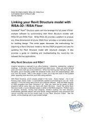
<strong>Wall</strong> Summary Detail ReportRISA-3D <strong>Wood</strong> <strong>Panel</strong> <strong>Tutorial</strong>Company : Mar 15, 2012Designer : 10:20 AMJob Number : WP1 (In-Plane)Checked By:_____GENERALCode: AF&PA NDS-05/08:A...GEOMETRYTotal Height : 120 inDesign Method : SegmentedTotal Length : 192 in<strong>Wall</strong> Material : DF/SPineMax H/W Ratio : 3.00<strong>Panel</strong> Schedule : IBC06-09 <strong>Panel</strong> Data...Sel. Shear <strong>Panel</strong> : S1_5/16_6d@4DESIGN DETAILSENVELOPED RESULTSControllingShear Region Shear <strong>Panel</strong>R6R5H1R4R2H2R3MATERIALSDescription Material SizeTop Pl DF/SPine 2-2X6Sill DF/SPine 2X6<strong>Wall</strong> Stud DF/SPine 2X6Chord DF/SPine 2-2X6Shear Shear Controlling Hold-down Hold-down Chord Chord StudUC LC Hold-down UC LC UC LC UCR6 S1_5/16_6d... 0.976 5 (W) HDU2-SD... 0.590 8 (W) 0.128 4 (W) 0.035 1REGION INFORMATIONFull-Height H/W Shear ShearHold-down Hold-down Chord Chord Stud StudRegion Label Ratio UC LC Hold-down UC LC UC LC UC LCR1 3.00 0.515 4 (W) HDU2-SDS2.5_...0.566 9 (W) 0.125 4 (W) 0.028 1R4 3.00 0.506 4 (W) HDU2-SDS2.5_...0.550 8 (W) 0.128 4 (W) 0.035 1R6 3.00 0.976 5 (W) HDU2-SDS2.5_...0.590 8 (W) 0.128 5 (W) 0.026 1OPENING INFORMATIONHeaders of openings are not designed for Segmented walls.Please choose Perforated or FTAO design method to get header design.R1StudLCGeneral/Geometry/MaterialsThe top section of the detail reportechoes the entire user defined input alsosummarizing the selections. The shear panelselected is shown as well as the MaximumH/W ratio for all the regions.<strong>Wall</strong> Region DrawingThis drawing shows the regions andopenings with hold-down locations for yourreference.Design DetailsThe Enveloped Results will display thecontrolling region, with the maximum Unitychecks for Shear, Hold-down, and Studs.The Region Information will show the unitychecks for all the regions. The openingsare not design for Segmented walls. Thedeflection results are shown for the FEAsolution as well as the NDS calculationmethod.DEFLECTION RESULTSMaximum RegionFinite Element Shear StiffnessDeflection (in) Deflection LC Deflection (in) Adjustment Factor (SSAF).4038 (R6) 5 .2515 1RISA-3D Version 10.0.0 [C:\RISA\<strong>Wood</strong> <strong>Wall</strong>.r3d]Page 119
RISA-3D <strong>Wood</strong> <strong>Panel</strong> <strong>Tutorial</strong>To navigate the Detail Report, you will need to select Region, <strong>Wall</strong>or Opening at the top of the screen.• Select the Region report by clicking on the button on the left.• You can also navigate to other Regions by clicking on the button.20
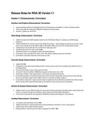
RISA-3D <strong>Wood</strong> <strong>Panel</strong> <strong>Tutorial</strong>Regions In-Plane Detail ReportCriteria/Materials/GeometryThe top section of the detail report echoesthe entire user defined input.Envelope DiagramsThe next section will display the envelopeaxial, shear and moment diagrams.Design SummaryThis section provides the capacity andstrength values at the section in the wallwhere the combined check is maximum, aswell as governing load combinations.The shear capacity is taken from theallowable shear value from the Table 2306.4.1of the IBC 06. The shear provided is adjustedby the 2w/h if the H/W ratio exceeds 2:1 perNDS/2008 Special Provisions for Wind andSeismic 4.3.4.1.The Deflection listed is based on theNDS/2008 Special Provisions for Wind andSeismic Eq. 4.3-1.Note: This is the theoretical deflection of thewall and may differ from the deflection foundfrom the FEA within RISA.21
RISA-3D <strong>Wood</strong> <strong>Panel</strong> <strong>Tutorial</strong>• Click to close the Detail Report.• Right-click to escape from the Detail selection.Let’s review the results graphically:• Double click on the wall to open the <strong>Wall</strong> <strong>Panel</strong> Editor and you’ll seethe designed wall detailed with the chords, studs and shear panelinformation.Let’s take a minute to review all the different components that make up thewall element:22
RISA-3D <strong>Wood</strong> <strong>Panel</strong> <strong>Tutorial</strong>Perforated ResultsReviewing Results:• Select the <strong>Wall</strong> <strong>Panel</strong> Design spreadsheet from the Results toolbar(If you don’t see your Results toolbar, click the icon).• To view the different results for wall panels click on the tabs at thetop: <strong>Wood</strong> <strong>Wall</strong> Axial, <strong>Wood</strong> <strong>Wall</strong> In-Plane.The <strong>Wood</strong> <strong>Wall</strong> Axial results provide the code checks relevant to axialloads of the wall. Here we see similar information that was provided for theSegmented design described above.Perforated design uses the entire wall panel,rather than the regions so the results will beper wall panel therefore N/A is displayed inthe Region column.The In-Plane results provide the code checks for the shear wall behavior ofthe wall.Note: The chords are the vertical hold downmembers/posts at both ends of every wall forPerforated design method.The Shear <strong>Panel</strong> Label describes the shear panels selected for the wall.The designation N/A is shown for the regions because Perforated design isbased on the entire wall rather than regions.• Close the <strong>Wall</strong> <strong>Panel</strong> Design spreadsheet.Let’s take a closer look at the wall by viewing the Detail Report:• Left click the Detail button on the left hand side of the screen.• Click anywhere on the wall panel.The Detail Report will open.24
RISA-3D <strong>Wood</strong> <strong>Panel</strong> <strong>Tutorial</strong>Perforated <strong>Wall</strong> Summary DetailReportGeneral/Geometry/MaterialsThe top section of the detail report echoesthe entire user defined input. The <strong>Wall</strong>H/W Ratio is checked against the aspectratio limits given in Table 4.3.4 of the NDS2008 Special Design Provisions for Wind& Seismic (SDPWS). The opening heightinformation is given in order to calculate theCo.Design DetailsThis section displays the selected shearpanel and hold downs. The maximum unitshear is also shown.The shear stiffness adjustment factor forwall panels is intended to allow the user toadjust the stiffness of his walls so that theymatch the APA deflection calculations. Thisadjustment affects the stiffness of theentire wall.You can modify this adjustment factor in the<strong>Wall</strong> <strong>Panel</strong> spreadsheet.25
RISA-3D <strong>Wood</strong> <strong>Panel</strong> <strong>Tutorial</strong>To navigate the Opening Detail Report, you will need to selectOpening at the top of the screen.• Select the Opening report by clicking on the button on the left.26
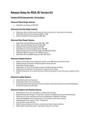
Perforated Header DetailReportCompany : Mar 15, 2012Designer : 10:31 AMJob Number : WP1 : H1Checked By:_____CRITERIACode : AF&PA NDS-05/08: ASDGEOMETRYOpening Height : 80<strong>Wall</strong> Type : PerforatedOpening Width : 32h/w ratio : 2.5Note: No header design for load combinations containing seismic or wind categories.ENVELOPE DIAGRAMS (Header)Max: .1272 at 0 inVkininMATERIALSDescription Material SizeHeader DF/SPine 2-2X6Sill DF/SPine 2X6Trimmer DF/SPine 6x6RISA-3D <strong>Wood</strong> <strong>Panel</strong> <strong>Tutorial</strong>Criteria/Materials/GeometryThe top section of the detail report echoesthe entire user defined input from the <strong>Wall</strong><strong>Panel</strong> Editor.Envelope Diagrams (Header)The next section will display the envelopeaxial, shear and moment diagrams.Min: -.1306 at 384 inMk-ftMax: .0446 at 192 inNote: axial forces are not considered in the design of the member.DESIGN DETAILSHEADERMax Bending CheckLocationEquation0.03016 in3.9-3Max Shear CheckLocationGov LCCD 0.900 RB 4.422 CL 1.000Cr 1.000Fb1'Fv'(ksi) Cm Ct CF1.17 1 1 1.3.1575 1 1Le-Bending• Click to close the Detail Report.0.075 (y)32 in132 inDesign SummaryThis section provides the bending and shearcode checks as well as governing locationand code equation combinations. The codedesign factors are also displayed.Note: In the Help file within RISA-3D and theRISA-3D General Reference both provideexplicit descriptions of nearly all of thevalues in the report.• Right-click to escape from the Detail selection.RISA-3D Version 10.0.0 [C:\RISA\<strong>Wood</strong> <strong>Wall</strong>.r3d]Page 127
RISA-3D <strong>Wood</strong> <strong>Panel</strong> <strong>Tutorial</strong>Designing the <strong>Wall</strong>: ForceTransfer Design MethodLet’s modify the wall and change the Design Method to ForceTransfer Around Openings:• Double click on the wall panel to open the <strong>Wall</strong> <strong>Panel</strong> Editor.• We’ll now switch the Design Method to Force Transfer shown on the<strong>Wall</strong> <strong>Panel</strong> Editor.Note: The Force Transfer Around Openingsmethod relies on reinforcement or straps,which is limited to windows only.Thus, to use this method you cannot have adoor opening.Note: Select Yes when asked to clear the current results.Let’s change the drawing grid to locate the openings:• In the Draw Toolbox, click in the box next to the Grid Increments H(Horizontal), clear the current entry and type 36,40,36• In the Draw Toolbox, click in the box next to the Grid Increments V(Vertical), clear the current entry and type 3@40.• Press the Tab key.• Toggle the grid display on and off by clicking the icon.We’ll need to delete the door opening and delete all the regions.• Click on the Delete button and click on ALL the regions.• Click on the door opening.• Right click to escape.28
RISA-3D <strong>Wood</strong> <strong>Panel</strong> <strong>Tutorial</strong>Now let’s create a window opening:• Click on the Create New Openings icon at the top left of the <strong>Wall</strong><strong>Panel</strong> Editor to create an opening.• Left click on the bottom left corner (36,40,0),To display the wall panel as shown to theleft, be sure to use the <strong>Wood</strong> View Controlsto Toggle the display of the <strong>Wall</strong> Studs ,Chords and Sill Plates .• Move the mouse to the top right corner (76,80,0) and left click on thegrid intersection.• Right click to escape.Let’s define the regions for the wall:• To define Regions inside the wall for design/analysis of the woodshear wall: Select the Generate <strong>Wall</strong> Regions Automaticallyicon.29
RISA-3D <strong>Wood</strong> <strong>Panel</strong> <strong>Tutorial</strong>• Click on the OK to exit the <strong>Wall</strong> <strong>Panel</strong> Editor.The loads are still applied, let’s run the analysis:• Click the Analysis and Design Icon.• Select the Batch Solution of Marked Combinations radio button.Designing for the Batch results allows us tosee the Detail Report as well as design forevery load combination.• Click Solve.30
Force Transfer ResultsRISA-3D <strong>Wood</strong> <strong>Panel</strong> <strong>Tutorial</strong>Reviewing Results:• Select the <strong>Wall</strong> <strong>Panel</strong> Design spreadsheet from the Results toolbar.(If you don’t see your Results toolbar, click the icon).• To view the different results for wall panels click on the tabs at thetop: <strong>Wood</strong> <strong>Wall</strong> Axial, <strong>Wood</strong> <strong>Wall</strong> In-Plane.The <strong>Wood</strong> <strong>Wall</strong> Axial results provide the code checks relevant to axialloads of the wall. Here we see similar information that was provided for theSegmented design described above.The In-Plane results provide the code checks for the shear wall behavior ofthe wall.Force Transfer Design uses the entire wallpanel, rather than the regions so the resultswill be per wall panel therefore N/A isdisplayed in the Region column.The Shear <strong>Panel</strong> Label describes the Shear <strong>Panel</strong>s selected for the wall.The designation N/A is shown for the regions because Force TransferAround Openings design is based on the entire wall rather than regions.• Close the <strong>Wall</strong> <strong>Panel</strong> Design spreadsheet.Let’s take a closer look at the wall by viewing the Detail Report:• Left click the Detail button on the left hand side of the screen.• Click anywhere on the wall panel.31
RISA-3D <strong>Wood</strong> <strong>Panel</strong> <strong>Tutorial</strong>Force Transfer Summary DetailReportGeneral/Geometry/MaterialsThe top section of the detail report echoesthe entire user defined input.Design DetailsThe shear stiffness adjustment factor forwall panels is intended to allow the user toadjust the stiffness of his walls so that theymatch the APA deflection calculations. Thisadjustment affects the stiffness of the entirewall. You can modify this adjustment factorin the <strong>Wall</strong> <strong>Panel</strong> spreadsheet.This section displays the selected shearpanel and hold downs. The maximum unitshear is also shown is comes from themaximum block unit shear in the Openingreport.Cross Section DetailingThe last section will provide a crosssectional drawing of the entire wall with allof the wall elements shown graphically. TheChord forces and Hold Down Forces are themaximum values with the LC that governed.32
RISA-3D <strong>Wood</strong> <strong>Panel</strong> <strong>Tutorial</strong>To navigate the Opening Detail Report, you will need to selectOpening at the top of the screen.• Select the Opening report by clicking on the button on the left.33
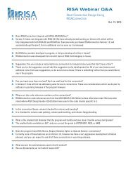
RISA-3D <strong>Wood</strong> <strong>Panel</strong> <strong>Tutorial</strong>Force Transfer Header DetailReportCriteria/Materials/GeometryThe top section of the detail report echoesthe entire user defined input.Envelope Diagrams (Header)The next section will display the envelopeshear and moment diagrams.FTAO & Opening StrapsThese sections map out the openings, andthe strap forces Required Capacity. Thesheathing resists the shear forces. Theaverage shear force in each block of thewall (numbered 1~8 as shown in the imageabove) is used as the controlling shear forcein that location. The maximum shear in eachof these locations will control the design ofthe wall and will be displayed in the <strong>Wall</strong>Summary Detail report. The program usesan area weighted average of the Fxy plateforces to determine the average shear foreach block.Design DetailsThis section provides the bending and shearcode checks as well as governing locationand code equation combinations. The codedesign factors are also displayed.Note: In the Help file within RISA-3D and theRISA-3D General Reference both provideexplicit descriptions of nearly all of thevalues in the report.34
RISA-3D <strong>Wood</strong> <strong>Panel</strong> <strong>Tutorial</strong>ConclusionIf you have completed the tutorial you should now be familiar with the wood wall panel in RISA-3D. RISA-3D has wallpanels in Masonry, <strong>Wood</strong>, Concrete and General materials. To learn more about the other materials or if you wish to knowmore about specific features, you can refer to the RISA-3D General Reference or the Help from within RISA-3D.If you have any questions, comments or suggestions feel free to email us at support@risatech.com, call us at 949-951-5815, or FAX 949-951-5848.Thank you for choosing RISA!35