FloorGenRef.pdf - RISA Technologies
FloorGenRef.pdf - RISA Technologies
FloorGenRef.pdf - RISA Technologies

You also want an ePaper? Increase the reach of your titles
YUMPU automatically turns print PDFs into web optimized ePapers that Google loves.
<strong>RISA</strong>FloorRapid Interactive Structural Analysis – Floor SystemsVersion 6.0- General Reference26632 Towne Centre Drive, Suite 210Foothill Ranch, California 92610(949) 951-5815(949) 951-5848 (FAX)www.risatech.com
Copyright 2012 by <strong>RISA</strong> <strong>Technologies</strong>, LLC All rights reserved. No portion of the contents of thispublication may be reproduced or transmitted in any means without the express written permission of<strong>RISA</strong> <strong>Technologies</strong>, LLC.We have done our best to insure that the material found in this publication is both useful and accurate.However, please be aware that errors may exist in this publication, and that <strong>RISA</strong> <strong>Technologies</strong>, LLCmakes no guarantees concerning accuracy of the information found here or in the use to which it may beput.
Table of ContentsTable of ContentsBefore You Begin ............................................. 1Overview ......................................................... 1Hardware Requirements ................................ 1Program Limits ............................................... 2License Agreement ........................................ 2Maintenance ................................................... 4Installation ...................................................... 4Application Interface ....................................... 5Main Menu ...................................................... 5Shortcut Menu ................................................ 8Toolbars .......................................................... 8Dynamic View Controls .................................. 11Shortcut Keys and Hot Keys .......................... 12Status Bar ....................................................... 13Windows ......................................................... 14Modes ............................................................. 15Beams ............................................................... 16Drawing Beams .............................................. 17Drawing Infill Beams ....................................... 18Modifying Beam Properties ............................ 21Modifying Beam Design Parameters .............. 22Beams – Primary Data ................................... 23Beams Spreadsheet - Detailing Data ............. 24Beams - Results ............................................... 26Single Angle Results ...................................... 26Beam Deflection Results ................................ 26Beam End Reactions ...................................... 28Beam Vibration Results .................................. 29Cold Formed Steel - Databases ...................... 30Custom vs. Manufacturer Shapes .................. 30Cold Formed Shape Types ............................ 31Cold Formed Steel - Design ............................ 33Design Parameters ......................................... 33Phi Factors ..................................................... 36Design Results ............................................... 37Code Checks .................................................. 37Shear Results ................................................. 38Bending Results ............................................. 39Column Results .............................................. 40Assumptions and Limitations .......................... 41Special Messages .......................................... 42Columns ............................................................ 43Drawing Columns ........................................... 44Modifying Column Properties ......................... 45Modifying Column Design Parameters ........... 46Column Stacks and Physical Columns ........... 47Columns Spreadsheet .................................... 48Column Stacks Spreadsheet .......................... 51Column Stack Manager .................................. 52Columns - Results ........................................... 55Column Forces Spreadsheet .......................... 55Column Moments ........................................... 57Column Skip Loading ..................................... 59Concrete - Database ........................................ 61Rebar Layout Database .................................. 61Concrete - Design ............................................ 66Concrete Spans .............................................. 66Concrete Design Parameters - Columns ........ 66Concrete Design Parameters - Beams ........... 68T-beam & L-beam Sections ............................ 70Parabolic vs. Rectangular Stress Blocks ........ 71Biaxial Bending of Columns ............................ 71Limitations - General ...................................... 72Limitations - ACI ............................................. 72Limitations - Canadian Code .......................... 73Limitations – Aus / NZ Codes ......................... 73Limitations - British ......................................... 73Limitations - Euro ............................................ 73Limitations - Indian ......................................... 74Limitations - Saudi Code ................................ 74General Reference ManualI
Table of ContentsSpecial Messages .......................................... 74Concrete - Design Results .............................. 76Beam Results ................................................. 76Column Results .............................................. 81Concrete Detail Reports ................................. 83Beam Detail Reports ...................................... 83Column Detail Reports ................................... 86Connections ..................................................... 881. Completing the Model ................................ 882. Defining Connection Rules ......................... 883. Assigning Connection Rules ...................... 89Connections Spreadsheet .............................. 904. Assigning Load Combinations .................... 915. Designing Connections .............................. 926. Connection Results Viewing ....................... 92Connection Results Browser .......................... 92Viewing Results Graphically ........................... 93Other Considerations ..................................... 94Customizing <strong>RISA</strong>Floor .................................. 99Save as Defaults ............................................ 99Preferences .................................................... 99Decks and Slabs .............................................. 104Creating Slab Edges and Openings ............... 104Modifying Slab Edges and Openings ............. 106Assigning Slab and Deck Properties .............. 107Deck Properties - General .............................. 108Deck Properties - Material Type ..................... 109Deck Properties - Loads ................................. 113Slab Edge and Opening Perimeters ............... 114Member Design Optimization ......................... 115Member Design Lists ...................................... 115Member Design Rules – Size / U.C................ 117Member Design Rules – Deflection ................ 118Member Design Rules – Concrete Rebar ...... 118Design Rules - Diaphragms ........................... 119Member Redesign Dialog ............................... 120Diaphragms ...................................................... 122Rigid Diaphragms ........................................... 122Semi-Rigid Diaphragms .................................. 123Flexible Diaphragms ....................................... 123Diaphragms Spreadsheet ............................... 126Diaphragm Modeling Tips ............................... 126DXF Files ........................................................... 128Importing DXF Files ........................................ 128Exporting DXF Files ........................................ 130DXF Element Numbers ................................... 132DXF File Format ............................................. 132File Operations ................................................. 135Starting Off ...................................................... 135Importing and Exporting Files ......................... 135Automatic Backup ........................................... 135Floors ................................................................ 137Creating a New Floor ...................................... 137Deleting a Floor .............................................. 137Floors Spreadsheet ........................................ 138Parent / Child .................................................. 139Global Parameters ........................................... 140Description ...................................................... 140Solution ........................................................... 141Codes ............................................................. 143Composite ....................................................... 145Wind ................................................................ 146Seismic ........................................................... 146Concrete ......................................................... 148Graphic Display ................................................ 150Multiple Windows ............................................ 150Controlling the Model View ............................. 151Viewing Part of the Model ............................... 153Saving and Retrieving Model Views ............... 153Graphic Display - Plot Options ....................... 154Beams/Columns/Walls ................................... 154Points/Decks/Slabs ......................................... 155Loads .............................................................. 157Miscellaneous ................................................. 158II<strong>RISA</strong>Floor v6
Table of ContentsGraphic Editing ................................................ 160Drawing and Modification Features ................ 160Undo Operations ............................................ 161Redo Operations ............................................ 161Project Grid ..................................................... 161Drawing Grid ................................................... 163Snap Points .................................................... 166Copying Model Elements ............................... 167Deleting Elements .......................................... 172Re-Labeling Selected Elements ..................... 173Graphic Selection ............................................ 174Selection Modes ............................................. 174Inverting Selections ........................................ 175Criteria Selections .......................................... 175Locking Selections ......................................... 178Graphic Selection from Spreadsheets ........... 178Saving Selections ........................................... 178Help Options .................................................... 180Electronic Help File ........................................ 180Context Sensitive Help ................................... 180<strong>RISA</strong> <strong>Technologies</strong> Online ............................. 180Tool-tips .......................................................... 180Tutorial ............................................................ 180Hot Rolled Steel - Databases .......................... 181Hot Rolled Steel - Design ................................ 184Design Parameters Spreadsheet ................... 184Member Design Parameters - General .......... 186Member Design Parameters - AISC Codes ... 188Hot Rolled Design Parameters - Canadian .... 189Hot Rolled Design Parameters - British ......... 190Hot Rolled Design Parameters - EuroCode ... 190Hot Rolled Design Parameters - Indian .......... 191General Limitations ........................................ 191Limitations - AISC ........................................... 192Limitations - Canadian .................................... 192Limitations - British ......................................... 193Limitations - EuroCode ................................... 193Limitations - Indian ......................................... 193Limitations - New Zealand and Australia ........ 193Special Messages - AISC ............................... 194Special Messages - Canadian ........................ 194Special Messages - Eurocode ........................ 195Hot Rolled Steel - Composite Beam Design . 196Pre-Composite Design ................................... 196Post-Composite Design - ASD (AISC 9th) ..... 196Post-Composite Design - LRFD ..................... 197Deflection Design ........................................... 197Studs and Stud Distribution ............................ 197Deck Ranking ................................................. 198Effective Width Calculation ............................. 198General Limitations ......................................... 199Limitations / Assumptions for CSA Composite ............................Troubleshooting Composite Design ............... 200Detail Reports for Composite Design ............. 200Hot Rolled Steel - Design Results .................. 202Design Results ............................................... 202Code Checks .................................................. 203Shear Results ................................................. 204Bending Results ............................................. 205Column Results .............................................. 206Loads ................................................................ 208Self Weight (Gravity Load) ............................. 208Load Cases ..................................................... 208Load Categories ............................................. 209Modifying Loads ............................................. 210Deleting Loads ................................................ 210Load Direction ................................................ 210Loads - Load Types ......................................... 212Area Loads ..................................................... 212Tapered Area Loads ....................................... 215Deck Loads ..................................................... 215Line Loads ...................................................... 215Point Loads ..................................................... 217Loads – Live Load Reduction ......................... 220General Reference ManualIII
Table of ContentsOverview ......................................................... 220Reducible Load Types .................................... 220Special Live Loads ......................................... 220Area Calculations ........................................... 220Limitations ...................................................... 220Loads – Load Attribution ................................ 221One Way Deck ............................................... 221Two Way Deck ............................................... 222Loads - Load Combinations ........................... 223Load Combinations Spreadsheet ................... 223Transient Load Combinations ........................ 225Timber Design Load Duration Factor ............. 225Generating Building Code Combinations ....... 225Load Generation - Notional Loads ................. 229Vertical Load ................................................... 229Notional Load Generation Dialog ................... 229Notional Load Results .................................... 230Load Generation - Seismic Loads .................. 231Seismic Weight ............................................... 231Seismic Design Parameters ........................... 232Seismic Load Results ..................................... 234Load Generation - Wind Loads ...................... 236Wind Load Parameters ................................... 236Wind Load Results ......................................... 237Sloped Roof Wind Loads ................................ 239Wind Load Limitations .................................... 240Material Properties .......................................... 241Material Properties Spreadsheet .................... 241Material Take-Off .............................................. 245Cardinal Points ................................................ 246Overview ......................................................... 246Detailing Input and Modification: .................... 247Visualization of the Detailing Layer ................ 250File I/O ............................................................ 252Modeling Tips ................................................... 253Dummy Members ........................................... 253Stranded Columns .......................................... 253Stranded Walls ............................................... 254Modeling Hangers .......................................... 255P-Delta - Analysis ............................................. 256Wall Panels ..................................................... 256Leaning Column Effect ................................... 256Points ................................................................ 257Point Locations Spreadsheet.......................... 257Printing ............................................................. 259Printing Reports .............................................. 260Printing to a File .............................................. 260Graphics Printing ............................................ 261Results .............................................................. 263Saving Results ................................................ 263Results Spreadsheets .................................... 263Graphic Results .............................................. 264Clearing Results ............................................. 264Member Detail Report .................................... 264Concrete Member Detail Reports ................... 265<strong>RISA</strong>Floor and <strong>RISA</strong>-3D Integration ............... 266Lateral System Model Generation .................. 266Diaphragms .................................................... 267Gravity Loads.................................................. 267Wind Loads ..................................................... 267Seismic Loads ................................................ 267<strong>RISA</strong>Foundation Interaction ........................... 268<strong>RISA</strong>Foundation Interaction with <strong>RISA</strong>-3D ..... 268<strong>RISA</strong>Foundation Interaction with <strong>RISA</strong>Floor .. 270Limitations ....................................................... 270Shape Databases ............................................. 272Database Shape Types .................................. 272Hot Rolled Shapes .......................................... 272Cold Formed Shapes ...................................... 272Concrete Shapes ............................................ 272Wood Shapes ................................................. 272General Shapes .............................................. 272Database Files ................................................ 276Sloped Members .............................................. 277IV<strong>RISA</strong>Floor v6
Table of ContentsTips for Modeling on Sloped Floors ............... 279Limitations ...................................................... 279Solution ............................................................ 281Solution Method.............................................. 281Differences Between 3D and Floor ................ 281Difference Between Analysis and Design ...... 281Spreadsheet Operations ................................. 283Moving and Scrolling ...................................... 283Spreadsheet Keyboard Commands ............... 283Selecting Spreadsheet Cells .......................... 284Undoing Operations ....................................... 284Redoing Operations ....................................... 284Editing Spreadsheets ..................................... 284Moving and Copying Cell Contents ................ 286Finding in Spreadsheets ................................. 287Default Spreadsheet Data .............................. 287Special Spreadsheet Functions ...................... 287Steel Products (Joists and Joist Girders) ..... 288Steel Products Database ................................ 288Steel Products Design .................................... 288Design for Joists with Non-Uniform Loads ..... 289Joist Girders ................................................... 290Design Results - Steel Products ..................... 290Limitations ...................................................... 291Units .................................................................. 292Standard Imperial Units .................................. 292Standard Metric Units ..................................... 292Units Specifications ........................................ 292Vibrations - Floor Framing .............................. 294Vibrations Spreadsheet .................................. 294Calculation of Vibration Loads / Deflections ... 295Limitations ...................................................... 295Wall Panels ....................................................... 297Drawing Wall Panels ...................................... 297Modifying Wall Panels .................................... 298Wall Panel Spreadsheets ............................... 300Wall Panel Editor ............................................ 301Wall Panel Load Attribution / Load Transfer . 305Wall Panel Load Attribution ............................ 305Wall Panel Load Transfer ............................... 309Wall Panels - Results ....................................... 314Wall Panel Results ......................................... 315Concrete Wall Panel - Design ......................... 320Concrete Wall Input ........................................ 320Concrete Design Considerations .................... 321Concrete Lintel Considerations ...................... 322Concrete Wall Modeling Considerations ........ 323Concrete Wall - Design Rules ......................... 326Unity Check .................................................... 326Concrete Wall (Rebar) Rules .......................... 326Concrete Wall (Cover) Rules .......................... 327Concrete Wall Results ..................................... 330Concrete Wall Spreadsheet Results .............. 330Concrete Reinforcing Spreadsheet Results ... 330Concrete Wall Detail Reports ......................... 331Masonry Wall Panel - Design .......................... 338Masonry Wall Input ......................................... 338Masonry Wall Optimization ............................. 342Masonry Wall - Design Rules .......................... 343Unity Check .................................................... 343Masonry Wall General .................................... 343Masonry Wall In Plane Design ....................... 344Masonry Wall Out of Plane Design ................ 344Masonry Wall Lintel Design ............................ 345Masonry Wall Results ...................................... 347Masonry Wall Spreadsheet Results ............... 347Concrete Reinforcing Spreadsheet Results ... 347Masonry Wall Detail Reports .......................... 347Masonry Detail Reports - Lintels .................... 351Wood Wall - Design ......................................... 354Wood Wall Input ............................................. 354General Requirements for Shear Walls .......... 356General Program Functionality & Limitations . 361Wood Wall - Design Rules .............................. 366General Reference ManualV
Before You BeginBefore You BeginWelcome to the <strong>RISA</strong>Floor General Reference manual. Please read this topic prior to installing the program and payparticular attention to the License Agreement. If you agree to the terms of the license then read the Installation section andinstall the program. If you are a first time user of <strong>RISA</strong>Floor you should turn your attention to the User's Guide (a separatedocument) which is designed to get you up and running as fast as possible while still exposing you to the important featuresof the software.The User's Guide is designed to be read in two ways. If you are already familiar with structural modeling in general you canskip the supporting text and read only the underlined action items to quickly move through the tutorial. If you want morethorough explanations of the modeling process you may read all or some of the supporting text as you see fit.After you have gone through the User's Guide, use this General Reference for detailed information on any topic. The topicsare arranged in alphabetical order and are thoroughly indexed.Overview<strong>RISA</strong>Floor has been developed to make the definition, design and modification of floor systems as fast and easy as possible.Analysis, up to and including calculation of maximum deflections and stresses, may be done on structures constructed of anymaterial or combination of materials. Furthermore, complete member design optimization is provided for hot rolled and coldformed steel, NDS wood beams, concrete beams and columns, as well as steel or wood products.<strong>RISA</strong>Floor has both graphical modeling and spreadsheet input capabilities. Not only can you draw your model, there areexceptional generation tools that automatically layout floor elements. To modify your model input data directly, <strong>RISA</strong>Flooremploys a powerful, proprietary spreadsheet. The combination of these features makes modeling both intuitive and powerful.The model can be rapidly edited, solved, viewed, modified, re-solved, etc. The truly interactive nature of <strong>RISA</strong>Floor is itsprimary strength.With <strong>RISA</strong>Floor, all model editing, model solution, and results browsing is accomplished through the same interface andwithin the same program. The interactive approach offers several unique advantages such as the ability to do real time errorchecking of your model data, the ability to do rapid model editing, solution, editing, and re-solution without jumping fromone program to another, and the need for the user to learn only one program interface.You may access the features in <strong>RISA</strong>Floor by using the menu system, or the toolbars. The best way to learn <strong>RISA</strong>Floor is togo through the User's Guide. The advantage to this is that you are exposed to the tools <strong>RISA</strong>Floor provides AND the waysthat you can take advantage of them.Hardware RequirementsMinimum• Any Windows compatible computer with a Pentium 3 or better processor• Windows XP\Vista\Windows 7• 256 MB of RAM• 200 MB of hard disk space• Two or three button mouse• USB port (required for Stand-Alone version or the Network Host computer)Recommended• Windows XP\Vista\Windows 7• As much extended RAM as possible• As much free disk space as possibleGeneral Reference Manual 1
Before You BeginNote• Two button mouse with wheel• The amount of space needed by <strong>RISA</strong>Floor to solve a particular structural model depends on the size of themodel. <strong>RISA</strong>Floor has been written such that it will use as much RAM as is available. If this isn't enough,<strong>RISA</strong>Floor will start using HD space until enough memory is obtained to solve the problem. Of course, if<strong>RISA</strong>Floor is required to use HD space, the solution will be much slower. So, the more memory you haveavailable, the better. In general, 500 Megabytes (MB) of RAM is a good amount to solve most problems.However, if you will be regularly solving large problems, more memory will save you a lot of time in the longrun.Program Limits200 Floors1,000 Columns per Floor3,000 Beams per Floor500 Walls per Floor2,000 Point Loads per Floor2,000 Line Loads per Floor200 Area Load Polygons per Floor200 Tapered Area Loads per Floor200 Deck Polygons per Floor500 Materials500 Custom Wood Species5000 Load CombinationsDemonstration Version: While you can open and solve a larger model, the largest model that can be saved to disk with thedemonstration version is limited to a total of 4 walls and 3 Floors with a maximum of 30 members for each of the floors.License AgreementEND-USER LICENSE AGREEMENT FOR <strong>RISA</strong> <strong>Technologies</strong>, LLC® SOFTWAREThe <strong>RISA</strong>Floor software product (SOFTWARE PRODUCT) includes computer software, the associated media, any printedmaterials, and any electronic documentation. By installing, copying or otherwise using the SOFTWARE PRODUCT, youagree to be bound by the terms of this agreement. If you do not agree with the terms of this agreement <strong>RISA</strong> <strong>Technologies</strong>,LLC is unwilling to license the SOFTWARE PRODUCT to you. In such event you must delete any installations and destroyany copies of the SOFTWARE PRODUCT and return the SOFTWARE PRODUCT to <strong>RISA</strong> <strong>Technologies</strong>, LLC within 60days of purchase for a full refund.Copyright 2012 by <strong>RISA</strong> <strong>Technologies</strong>, LLC. All rights reserved. The SOFTWARE PRODUCT is protected by UnitedStates copyright laws and various international treaties. All rights not specifically granted under this agreement are reservedby <strong>RISA</strong> TECHNOLOGIES.1. SOFTWARE LICENSE. The SOFTWARE PRODUCT is licensed, not sold. All right, title and interest is and remainsvested in <strong>RISA</strong> <strong>Technologies</strong>, LLC. You may not rent, lease, or lend the SOFTWARE PRODUCT. You are specificallygranted a license to the use of this program on no more than one CPU at any given time. The Network Version of theSOFTWARE PRODUCT is licensed for simultaneous use on a certain maximum number of network stations that varies on aper license basis. As part of the license to use the SOFTWARE PRODUCT, the program user acknowledges the reading,understanding and acceptance of all terms of this agreement. The SOFTWARE PRODUCT may not be reviewed, compared2 <strong>RISA</strong>Floor v6
Before You Beginor evaluated in any manner in any publication without expressed written consent of <strong>RISA</strong> <strong>Technologies</strong>, LLC. You may notdisassemble, decompile, reverse engineer or modify in any way the SOFTWARE PRODUCT. If the SOFTWAREPRODUCT was purchased at a discounted price for educational purposes it may in no event be used for professional designpurposes. The terms of this license agreement are binding in perpetuity.2. DISCLAIMER. We intend that the information contained in the SOFTWARE PRODUCT be accurate and reliable, but itis entirely the responsibility of the program user to verify the accuracy and applicability of any results obtained from theSOFTWARE PRODUCT. The SOFTWARE PRODUCT is intended for use by professional engineers and architects whopossess an understanding of structural mechanics. In no event will <strong>RISA</strong> <strong>Technologies</strong>, LLC or its officers be liable toanyone for any damages, including any lost profits, lost savings or lost data. In no event will <strong>RISA</strong> <strong>Technologies</strong>, LLC or itsofficers be liable for incidental, special, punitive or consequential damages or professional malpractice arising out of or inconnection with the usage of the SOFTWARE PRODUCT, even if <strong>RISA</strong> <strong>Technologies</strong>, LLC or its officers have beenadvised of or should be aware of the possibility of such damages. <strong>RISA</strong> TECHNOLOGIES' entire liability shall be limited tothe purchase price of the SOFTWARE PRODUCT.3. LIMITED WARRANTY. <strong>RISA</strong> <strong>Technologies</strong>, LLC warrants that the SOFTWARE PRODUCT will operate but does notwarrant that the SOFTWARE PRODUCT will operate error free or without interruption. <strong>RISA</strong> <strong>Technologies</strong> sole obligationand your exclusive remedy under this warranty will be to receive software support from <strong>RISA</strong> <strong>Technologies</strong> via telephone,email or fax. <strong>RISA</strong> <strong>Technologies</strong> shall only be obligated to provide support for the most recent version of the SOFTWAREPRODUCT. If your version of the SOFTWARE PRODUCT is not the most recent version <strong>RISA</strong> <strong>Technologies</strong> shall have noobligation to provide support in any form. Except as stated above the SOFTWARE PRODUCT is provided without warranty,express or implied, including without limitation the implied warranties of merchantability and fitness for a particular purpose.4. PROTECTION DEVICE. In the event the SOFTWARE PRODUCT requires the use of a PROTECTION DEVICE tooperate, you are specifically prohibited from attempting to bypass the functionality of the PROTECTION DEVICE by anymeans. If the PROTECTION DEVICE becomes broken or inoperable it should be returned to <strong>RISA</strong> TECHNOLOGIES for areplacement. The replacement will not be provided if <strong>RISA</strong> TECHNOLOGIES can not affirm that the broken PROTECTIONDEVICE was originally provided by <strong>RISA</strong> TECHNOLOGIES for use with the SOFTWARE PRODUCT. A lost or stolenPROTECTION DEVICE will not be replaced by <strong>RISA</strong> TECHNOLOGIES.5. TERMINATION. <strong>RISA</strong> TECHNOLOGIES may terminate your right to use the SOFTWARE PRODUCT if you fail tocomply with the terms and conditions of this agreement. In such event you must delete any installations and destroy anycopies of the SOFTWARE PRODUCT and promptly return the SOFTWARE PRODUCT to <strong>RISA</strong> <strong>Technologies</strong>.6. CHOICE OF LAW. By entering into this Agreement in accordance with Paragraph 1, above, you have agreed to theexclusive jurisdiction of the State and Federal courts of the State of California, USA for resolution of any dispute you haverelating to the SOFTWARE PRODUCT or related goods and services provided by <strong>RISA</strong> <strong>Technologies</strong>. All disputes thereforeshall be resolved in accordance with the laws of the State of California, USA and all parties to this Agreement expresslyagree to exclusive jurisdiction within the State of California, USA. No choice of law rules of any jurisdiction apply."<strong>RISA</strong>" as applied to structural engineering software is a trademark of <strong>RISA</strong> <strong>Technologies</strong>.“APA” is a registered trademark of APA - The Engineered Wood Association“BCI” is a registered trademark of BOISE CASCADE WOOD PRODUCTS, L.L.C.“Georgia-Pacific” is a registered trademark of Georgia-Pacific Corporation"GPI" is a registered trademark of Georgia-Pacific Wood Products South LLC.“iLevel” is a registered trademark of Weyerhaeuser NR Company.“iLevel Trus Joist Microllam LVL” is a registered trademark of Weyerhaeuser NR Company.“iLevel Trus Joist Parallam PSL” is a registered trademark of Weyerhaeuser NR Company.“International Beams” is a registered trademark of International Beams, Inc."LPI" is a registered trademark of Louisiana-Pacific Corporation.“Nordic” is a registered trademark of Les Chantiers de Chibougamau ltée.“Pacific Woodtech” is a registered trademark of Pacific Woodtech Corporation.General Reference Manual 3
Before You Begin“Red” is a registered trademark of REDBUILT, LLC“Rebuilt” is a registered trademark of REDBUILT, LLC"RFPI" is a registered trademark of Roseburg Forest Products.“TimberStrand Trus Joist” is a registered trademark of Weyerhaeuser NR Company.“TJI” is a registered trademark of Weyerhaeuser NR Company..MaintenanceProgram maintenance provides all upgrades to <strong>RISA</strong>Floor, and discounts on new products.When your maintenance expires, you will be given the opportunity to continue program maintenance on an annual basis. Youare under no obligation to continue program maintenance, of course, but if you decide to discontinue maintenance you willno longer receive <strong>RISA</strong>Floor program upgrades and technical support.Complete program support is available to registered owners of <strong>RISA</strong>Floor and is included in the purchase price. This supportis provided for the life of the program. See Technical Support for a list of your support options.The “life of the program” is defined as the time period for which that version of the program is the current version. In otherwords, whenever a new version of <strong>RISA</strong>Floor is released, the life of the previous version is considered to be ended.<strong>RISA</strong> <strong>Technologies</strong> will support only the current version of <strong>RISA</strong>Floor.InstallationTo install <strong>RISA</strong>Floor please follow these instructions:1. Put the <strong>RISA</strong>Floor CD in your computer CD drive.2. If the CD starts automatically go to step 4. If the CD does not start after 10 seconds click the Windows Start buttonand select Run.3. In the Run dialog box type “d:\launch” (where “d” is the label of your CD drive) and then click the OK button.4. Follow the on-screen instructions.4 <strong>RISA</strong>Floor v6
Application InterfaceApplication InterfaceThe User's Guide (a separate document) contains a tutorial that leads you through the <strong>RISA</strong>Floor interface with an actualmodel. Consider going through the tutorial if you have not done so already, as it is the fastest way to learn the program.Although it requires some time up front, the tutorial will save you time and brainpower in the long run.The features that are available to you in <strong>RISA</strong>Floor may be accessed through the main menu, shortcut menus, toolbars andshortcut keystrokes. You may use any or all of these vehicles to interact with the software. The main menu has the advantageof containing all of the program options and features and may initially be the simplest to use, letting you learn just onesystem. The toolbars contain more common options and invoke with one click. The shortcut menus present options relevantto the task at hand. The shortcut keys provide a fast way to access features should you use the program often enough to makethem familiar to you. All of these features are discussed in the sections below. There are many ways to access features andthe method that you will use will simply be a matter of personal preference. The good news is that you have the options.The bar along the top of the screen is called the title bar and contains the name of the file that is currently open. The threebuttons on the far right side of the title bar are used to control the main window. The left button will shrink themain application window to a button on the taskbar. The middle button will shrink or maximize the window on your screen.The right button will close the window, prompting you to save changes if necessary. You will also see these buttons in otherwindows and they have basically the same functions there as well.The actual work that you do will be in the main area on the screen, which is called the workspace. When you open a modelview, a spreadsheet or a dialog it will be opened in the workspace and listed in the Window menu. You may have as manywindows open as you like.Main MenuAll of the program features may be accessed through the main menu system at the top of the screen beginning with File onthe far left and ending with Help or possibly Director on the far right. Clicking on each of these menus (listed below) willdisplay sub-menus that contain options that you may choose from. You may also select the main menus by using the ALTkey along with the underlined letter in the menu you wish to choose. You may then continue to use the keyboard to choosefrom the menu options. In addition, some of the menu options will have hot key combinations listed to the right of the option.These hot keys allow you to use the keyboard to access features without using the menu system.File MenuNew will close the current file, prompting for saving if necessary, and will open a new file.Open will close the current file, prompting for saving if necessary, and will open an existing file.Save will save the current file, prompting for a name if necessary.Save As will save the current file, prompting for a name.Import DXF File will create a new floor using an existing DXF file.Export will export the current file to a DXF, SDNF, or Pro-Steel exchange file.For more information on the interaction between <strong>RISA</strong> and other programs refer to Appendix E.Print will access <strong>RISA</strong>Floor printing options.Page Setup will present page setup options for printing.Recent Files The five most recent files will be listed at the bottom of the menu. Selecting one of these files will close thecurrent file, prompting for saving if necessary, and will open the selected file.Exit will close <strong>RISA</strong>Floor, prompting for saving if necessary.General Reference Manual 5
Application InterfaceEdit MenuUndo will undo the last edit that was applied to the model whether it was made graphically or in the spreadsheets. You maycontinue to apply Undo to remove up to 100 model edits.Redo will reverse the last undo that was applied to the model. You may continue to apply Redo to remove up to 100 undooperations.Copy will copy the selected spreadsheet cells or model view from the active window to the clipboard.Paste will paste data from the clipboard to the spreadsheet cells.Insert Line will insert a new line in the spreadsheet beneath the current line.Delete Line will delete the current spreadsheet line.Repeat Line will insert a new line in the spreadsheet beneath the current line and copy the data from the current line.Mark All Lines will select all of the lines in the spreadsheet.Unmark Lines will unmark any currently marked lines.Delete Marked Lines will delete the marked lines in the spreadsheet.Find will locate an item on the spreadsheet by its label.Fill Block will fill the marked block of cells with a valid entry.Math on Block allows you to add, subtract, multiply or divide the values in the marked block of cells.View MenuNew View will open a new model view window.Save or Recall Views allows you to save a view or recall a view that has previously been saved.Clone View makes a copy of the current view so you can modify one and maintain the other.Refresh All will refresh all of the windows that are open in the workspace.Select provides graphic select options that are also provided on the Selection Toolbar.Unselect provides graphic unselect options that are also provided on the Selection Toolbar.Save or Recall Selection States allows you to save a selection or recall a selection that has previously been saved.Zoom provides options for zooming in and out of the current model view.Rotate provides options to snap the model view to global planes or an isometric view.Plot Options opens the Plot Options.Render will turn rendering of the current model view on or off, depending on the current setting.Drawing Grid will turn the display of the Drawing Grid on or off, depending on the current setting.Project Grid will turn the display of the Project Grid on or off, depending on the current setting.Axes will turn the display of the global axes in the model view on or off, depending on the current setting.Loads will turn the display of the model loads on or off, depending on the current setting.Point Labels will turn the display of the point labels on or off, depending on the current setting. A third setting is alsoavailable where the points themselves are not shown at all.Beam Labels will turn the display of the beam labels on or off, depending on the current setting. However, if rendering isturned on, beam labels will not be visible in the model view.6 <strong>RISA</strong>Floor v6
Application InterfaceInsert MenuThe Insert Menu will help you insert new items into the model. Most of the options will provide a graphical method ofinsertion but some will open spreadsheets where appropriate. See Graphic Editing for specific information.Modify MenuThe Modify Menu will help you modify existing items in the model. Most of the options will provide a graphical method ofmodification but some will open spreadsheets where appropriate. The Delete Items Dialog may also be accessed via thismenu. See Graphic Editing for specific information.Spreadsheets MenuThe Spreadsheets Menu provides access to any of the input spreadsheets. See Spreadsheet Operations to learn how to workwithin the spreadsheets.Solve MenuClicking on the Solve Menu will immediately begin a solution to the model. See Solution for more information.Results MenuThe Results Menu provides access to any of the results spreadsheets. See Results Spreadsheets for more information.Tools MenuDelete All Unattached Points will delete any points that are not connected to beams, columns, decks, deck edges or loads.<strong>RISA</strong>-3D Data will allow you delete selected portions of the <strong>RISA</strong>-3D model that automatically generated by Floor. It willalso allow your to "re-start" the optimization of member sizes based on the current <strong>RISA</strong>Floor sizes.Preferences contain settings that let you customize the program. See Customizing <strong>RISA</strong> for more information.Customize Toolbar... allows you to modify the model view toolbar by adding, subtracting and re-ordering buttons. See thecustomizable toolbar section.Reset All Program Defaults will reset all customized settings to the original factory settings.Window MenuIn order to help you work with the model and the results, you are provided with many window arrangements to choose from.You may access them from the Window Menu. The best way to understand just what these 'tilings' do is to try them.Remember that once you choose a tiling you may adjust any of the windows as you wish.Help MenuHelp Topics opens the <strong>RISA</strong>Floor Help File so that you may search the contents and the index. See Help Options to learnabout getting help.Check for Updates runs an internal check for possible program updates. If your program is up to date, you will receive amessage saying you are up to date. If you are out of date, the check will offer you the option to email <strong>RISA</strong> <strong>Technologies</strong> forupgrade information if you are out of date for a major update. If you are out of date just a minor update, then we will sendyou to our website to upgrade.. This check is also offered during the installation process.About provides <strong>RISA</strong>Floor version and hardware key information.Director MenuGeneral Reference Manual 7
Application InterfaceIf you are working from within the <strong>RISA</strong> Building System (RBS), use this menu to switch between <strong>RISA</strong>Floor, <strong>RISA</strong>-3Dand <strong>RISA</strong>Foundation. If you are not working within the <strong>RISA</strong> Building System, the Director Menu will not be shown. See"<strong>RISA</strong>Floor and <strong>RISA</strong>-3D Integration" on page 266 for more information.The directory button is located at the far, far right hand side of the Main Menu Toolbar as shown in the image above.Shortcut MenuThe Shortcut Menu is also referred to as the Right-Click Menu. This is because to access the shortcut menu you simplyclick the RIGHT mouse button where you are working to see options that are relevant to what you are doing. For example ifyou are working in a model view the right click menu will provide options to help you modify the view and edit the modelgraphically. If you are working in a spreadsheet the menu will provide editing tools for that spreadsheet.This menu will appear wherever you RIGHT click the mouse. This way you do not need to move away from where you areworking to select the features you want to use.ToolbarsThe Toolbars provide buttons to help you access common commands and popular options in the menu system discussedabove. There are different toolbars that will appear as you work to build your model and browse your results. If at any timeyou are not sure what a particular button does, simply let your mouse hover over the button and a helpful tip will pop up andexplain the button.<strong>RISA</strong> ToolbarThe first horizontal toolbar located just below the Main Menu is called the <strong>RISA</strong> Toolbar. The buttons on this bar facilitatefile and window access. You may use these buttons to open files and windows and also to analyze the model.Window ToolbarThe Window Toolbar is the second horizontal toolbar located below the Main Menu. It gets its name because the buttonschange as you move from window to window in order to help you with what you are currently doing. When you are workingin a model view the buttons provide viewing tools, such as Rotate and Zoom, to assist you with that view. There are alsomany other results and information display toggles, including some icons with the drop down arrow next to them. Clickingthe arrow will show you the different view options for that icon. Clicking the icon itself will bring you back to the defaultview. Note that this model view toolbar is now fully customizable. See below for more information.Other model view windows that are open will not be affected so that each may show different information. When you areworking in a spreadsheet, editing tools are provided that are appropriate to that particular spreadsheet. Note that not all toolsare available with all spreadsheets. In fact there are many tools that are provided for one spreadsheet only. See SpreadsheetOperations for more information.Customizable Model View ToolbarThe model view toolbar is fully customizable. By creating your personalized toolbar, you can quickly access your mostfrequently used buttons. This can be done quickly and easily in just a few steps.1. Go to Tools menu and select Customize Toolbar.8 <strong>RISA</strong>Floor v6
Application Interface2. Select one of the toolbars by clicking in the box Available toolbar buttons, and click on Add to place them on thecurrent toolbar.3. Once you’ve moved the buttons to the Current Toolbar, you can rearrange them by clicking on Move Up or MoveDown.4. Click Close and you will see your selections on the model view toolbar.General Reference Manual 9
Application InterfaceNote:• You must have a model view as the current view to see this toolbar.• If you add more buttons than will fit on the toolbar the buttons that are at the end of the "Current toolbar buttons" willbe cut off.• The changes you have made will automatically be saved on a per-user (Windows User) basis, such that next time youopen the program the toolbar will be arranged per your preferences.For additional advice on this topic, please see the <strong>RISA</strong> News website: www.risanews.com. Type in Search keywords:Customized Toolbar.Selection ToolbarThe vertical toolbar on the left side of the screen is the Selection Toolbar. This toolbar will only be available when the activewindow is a model view. The buttons on this toolbar help you select and unselect items in the model in order to help youbuild and modify the model or view results. See Graphic Selection for more information.Drawing ToolbarAnother toolbar that is available is the Drawing Toolbar. Unlike those mentioned above, this toolbar is located in the modelview windows rather than in the main application window. This way the drawing tools stay close to where you are working.This toolbar controls modeling features that help you draw, load, and modify your model graphically. You may have morethan one view open and a Drawing Toolbar for each view. This way you can simultaneously draw columns in one windowand beams in another.The Drawing Toolbar may be displayed in any model view window by clicking on the Window Toolbar while in themodel view window. Some of the buttons on the toolbar are for one-time applications such as modifying the drawing grid.Other buttons place you in an editing mode, such as Draw Columns, that remains active until you cancel it. The current modeis indicated by the mouse pointer and by the state of the button. While in an editing mode the button will stay down until youclick it again or choose another button. See Graphic Editing for more information.This brings us to an important point. Some of the toolbar buttons remain down when you press them to indicate that you arein a certain mode or that something is either on or off. For example the Box Zoom button will stay down to indicate thatyou are currently in the zooming mode. The Show Drawing Toolbar button will remain down when you turn on this10 <strong>RISA</strong>Floor v6
Application Interfacetoolbar for the active window. You may be in more than one mode at the same time as long as they are not mutuallyexclusive.The Data Entry Toolbar is the vertical toolbar on the right side of the application window. It contains buttons that facilitatedata entry through the spreadsheets. The buttons on this toolbar provide quick access to the spreadsheets that are also listed inthe Spreadsheets Menu. You may open and close the toolbar by clicking the button on the <strong>RISA</strong> Toolbar.For additional advice on this topic, please see the <strong>RISA</strong> News website: www.risanews.com. Type in Search keywords: DataEntry.The Results Toolbar is the vertical toolbar on the right side of the application window that is placed over the Data EntryToolbar after the model has been solved. The buttons on this toolbar provide quick access to the results spreadsheets that arealso listed in the Results Menu. You may open and close the toolbar by clicking the button on the <strong>RISA</strong> Toolbar.Dynamic View ControlsWhen your current window is a graphical model view, you can use the mouse wheel to dynamically zoom, pan, or rotate thegraphical image. These functions are only available to users who have a mouse with a wheel button and whose computers arerunning the Windows XP operating system.Mouse ActionRolling the WheelForwardRolling the WheelBackwardClicking and holding theWheel ButtonClick and hold the Wheelbutton while pressing theShift keyModel View FunctionZoom InZoom OutGrab the image and pan in the direction ofmouse movementDynamically rotate the structure in thedirection of mouse movementDynamic Pan: Clicking and holding the mouse wheel button triggers the tool and allows the user to pan or drag the view tothe limit of scroll bars.Dynamic Zoom: This tool uses the wheel button on the mouse. Rotating forward zooms in and rotating backward zooms out.General Reference Manual 11
Application InterfaceDynamic Rotate: This tool is triggered by clicking and holding the mouse wheel button while holding the Shift key. Therotational movement will be based on the how the user drags the mouse cursor over the screen and the projection of globalaxis on the screen. For rotation about X axis, drag the cursor perpendicular to the projection of the global X axis. The samelogic applies for Y or Z axis rotations. When rotation is initiated, the system locks for rotation about that axis until the userreleases the middle mouse button.Zoom Previous/Next: Function keys F3 and F4 are associated with Zoom Previous and Zoom Next respectively. The systemholds a doubly linked list of zoom info. This list has 10 zoom-states in the list. The F3 or F4 keystroke moves the activepointer forward or backward on the list. Each window has its own zoom list.Dynamic Distance Tool: This tool triggers by pressing the F5 key. The user has to pick up two points on the screen and thesystem gives back the total and partial distance between points on the status bar.Shortcut Keys and Hot KeysShortcut Keys and Hot Keys allow you to use the keyboard to quickly access features. The difference between the two issimply that the shortcut keys are related to a specific window and will only work in that window while the hot keys willperform at most any time.General Hot KeysKey CombinationF1F5Ctrl-F1Ctrl-F2F7, Ctrl-F7Ctrl-CCtrl-VCtrl-NCtrl-OCtrl-SCtrl-PCtrl-ZAlt-FunctionHelp on the active windowActivates the Dynamic Distance ToolMain Help topicsCreate New viewCopy to the clipboardPaste from clipboardStart a new fileOpen an existing fileSave the current filePrintUndoAccess the menus by combining the Altkey with the underlined letter in the menuShortcut Keys available for Specific WindowsKey Combination Model View Window SpreadsheetCtrl-DOpen last graphic editing Delete Marked LinesdialogCtrl-GToggle Drawing ToolbarCtrl-ASelect AllCtrl-UUnselect allCtrl-FBlock Fill12 <strong>RISA</strong>Floor v6
Application InterfaceCtrl-MBlock MathCtrl-IInvert SelectionCtrl-L Toggle Lock unselected Unmark linesCtrl-Enter Press cell buttonF2 Open Plot Options Start/Stop Cell EditF3Insert lineF4Delete LineF5 Initiates the "Distance" tool FindF8Repeat Current LineF9Sort+ Zoom In- Zoom Out PgUp PgDwn Scrolling ScrollingSpreadsheet Hot Keys that open spreadsheetsKey Combination Unsolved model Solved ModelCtrl-Alt-C Point Coordinates Column ResultsCtrl-Alt-DLine LoadsCtrl-Alt-E Beams – Primary Data Deflection ResultsCtrl-Alt-FBending ResultsCtrl-Alt-GGlobal ParametersCtrl-Alt-HDesign ResultsCtrl-Alt-LLoad CombinationsCtrl-Alt-M Materials Material Take OffCtrl-Alt-NConcrete ReinforcingCtrl-Alt-PPoint LoadsCtrl-Alt-R Design Rules End ReactionsCtrl-Alt-SShear ResultsCtrl-Alt-UDesign ResultsStatus BarThe Status Bar passes useful information to you as you work. It is divided into four parts located along the very bottom ofthe main application window, just beneath the workspace.The left side of the status bar shows a solution flag to indicate the solved state of the model as follows:Solution Type Unsolved SolvedGeneral Reference Manual 13
Application InterfaceStaticAfter a solution has been performed and modifications are made to the model, the “S” icon changes to (yellow). Thisindicates that the model has been solved but then modifiedTo the right of the solution flags there are three message boxes.The first and largest box lets you know what you are currently doing. If you are in a spreadsheet, this box will contain theexplanation of the current cell. If you are working in a model view and select a graphic editing option, look to this box forinformation on how to use the feature.The second box is used to pass you units of the current spreadsheet cell.The third box indicates the coordinates of the mouse when a model view is active. The mouse coordinates that are displayedare the coordinates of the grid point or joint that is nearest to the mouse.WindowsModeling the structure will take place within model views and spreadsheets, each in their own window that may be movedaround the workspace and sized as you wish. The ability to have multiple model views and multiple spreadsheets open at onetime is a powerful feature. The options in the Window Menu are provided to help you manage these windows.These windows contain three buttons in the upper right corner to help you minimize, maximize and close thewindow, respectively. There are also scroll boxes to help you view information that is outside of the window viewing area.Click the scroll bar buttons or drag the scroll box to advance the display in one direction or another.Model ViewsModel View windows show a graphic view of the model. Open a new view with the button.You may open as many model view windows as you like. This is especially helpful when working in close on large models.You might have one overall view and a few views zoomed in and rotated to where you are currently working. You may alsohave different information plotted in multiple views.One thing to remember is that the toolbars that are displayed depends upon what window is active. The active window is theone with the blue title bar. For example, if you are looking for the zoom toolbar button and the active window is aspreadsheet you need to select a model view first before you can access the zooming tools.SpreadsheetsSpreadsheet windows are made up of rows and columns of data cells. If you wish to add or edit data in a spreadsheet cellyou click on the cell, making it the active cell, and then edit the cell. This active cell is simply the green cell that movesaround the spreadsheet as you hit the cursor keys (← , →), Page Up, Page Down, Home, End, etc. There is always one andonly one active cell, which is the cell that has the “attention” of the keyboard.You may also select blocks of data to work on. You can select a block of data by clicking and holding the mouse button onthe first cell in the block and then dragging the mouse to the opposite corner of the block and releasing the mouse.DialogsA Dialog is a third type of window and is used to access a specific function within the program. Another powerful feature isthat most of the dialogs may be left open while you edit the model, making it easy to make adjustments as you work. Youwill find that dialogs are very easy to work with. There are Help buttons that will bring you directly to the relevant topic inthe help file.14 <strong>RISA</strong>Floor v6
Application InterfaceModesThere are three basic program modes (View, Select, and Edit) and a mode hierarchy to allow you to move between themeasily. While you are editing the model you may select items to edit. When you are finished selecting you will be returned toediting. Likewise, while you are selecting items you can adjust the view and then be returned to selecting.Different mouse cursors are used with each mode to make it clear what the current mode is.View Mode is the upper level mode that allows you to adjust the view by zooming in and out, rotating and setting plotoptions. This mode supersedes all other modes so that you may do these things at any time, and then be returned to theprevious mode. This mode does not cancel other modes so that when you are finished adjusting the view you are returned towhat you were doing. See Graphic Display for more information.Select Mode is the middle level mode that allows you to make a graphic selection of joints, members and plates. This modesupersedes the Edit Mode but not the View Mode. This means that you can make a selection while in the middle of editingthe view and when you are finished you are returned to the editing feature that you were using. It also means that you mayadjust the view while remaining in the same Select Mode. See Graphic Selection for more information.Edit Mode is the lower level mode that allows you to graphically edit the model. You may make selections and adjust theview while in the edit mode such that when you are finished selecting you will be returned to the Edit Mode. Some EditMode features have options on how you apply the edit. See Graphic Editing for more information.Note• The default mode is the mode you are in if you are not in any other mode and is indicated by the standardmouse cursor. The default mode is a selection mode where you can select/unselect individual items by clickingon them.• You may use the ESC key or the right mouse button to cancel a mode.General Reference Manual 15
BeamsBeamsOne of <strong>RISA</strong>Floor’s primary tasks is the modeling, loading, and design of beams. This includes automatic attribution of loadsfrom the deck system, live load reduction, and design optimization for the desired code and criteria. Loads modeled on thedeck are attributed to the beams and the beams transfer the loads through the floor framing to walls and columns andultimately down to the foundation. Automatic live load reductions may also be applied. With the use of beam end releasesyou may define simply supported or fixed end / continuous beams.The beams can function to resist only gravity loads, where they are analyzed and designed completely within <strong>RISA</strong>Floor, orthey can function as part of a lateral load resisting system. The lateral systems can be analyzed in <strong>RISA</strong>-3D for load casessuch as wind or seismic events and the beams are designed for combined gravity and lateral forces. See <strong>RISA</strong>-3D Integrationfor more information.Beam data may be viewed and edited in two ways: graphically in the Information Dialog or in the Beams Spreadsheet. SeeBeams – Primary Data for descriptions of the beam data.Beams can be specified as Hot Rolled Steel, Cold Formed Steel, Wood, Concrete, and Steel or Wood Products. Refer to thespecific sections for Steel Design, Wood Design, and Steel or Wood Product Selection for more info on the design or codechecking of beams. The shape groups available for each designation are listed below.DesignationHot RolledCold FormedWoodConcreteSteel ProductWood ProductShape GroupWide FlangeChannelTubeSingle AngleDouble AnglePipeW_TeeCUCSZUZSHURectangularRectangular DoubleRectangular TripleRoundGlulam WesternGlulam Southern PineRectangularRectangular MMSteel JoistWood JoistTJI JoistLPI JoistBCI JoistAny available material listed in the Materials spreadsheet can be assigned to a beam. See Material Properties for moreinformation. All beam shapes and material properties may be assigned graphically either as you draw or later as amodification to the beams.General Reference Manual 16
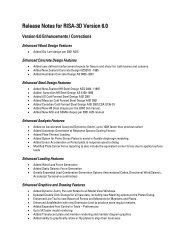
BeamsDrawing BeamsTo create new beams you can draw from point to point, point to member, and member to member. Point to Point is whenyou want to draw a beam between columns, points, or a combination of column and a point. Point to member is when youdraw a beam from a column or snap point to a member with an offset distance from the member end. Member to member iswhen you draw a beam between members using an offset distance for both members. For member offsets click toward theend of the member that you want the offset measured from. You can set all of the beam properties before drawing them oryou can modify these properties after you draw a beam. Graphically modifying properties is discussed in the next section.See Beams– Primary Data for information on the beams and beam properties themselves.To draw beams, click on the Drawing Toolbar to open the Draw Beams dialog. Enter the beam type, material, shapegroup, redesign rules, span type, function, orientation, end releases, and drawing option, click Apply and draw beamsaccordingly.If the Keep Spans Continuous is not checked, each beam you draw will be divided up at each beam or column intersectionfound along its length. The end conditions for each beam will be those specified in the End Releases field. If the KeepSpans Continuous IS checked, the first point you click on is the start of the beam and gets the Start end release that isspecified in the End Releases field. The last point you click on gets the 'End' end release that is specified in the End Releasesfield. For these continuous beams, all intermediate columns or beams that occur along its length will be fully fixed to thecontinuous beam.As you draw, the coordinates of the nearest grid point or snap point are shown in the status bar in the lower right corner. Thenew beams will be shown on screen and will be recorded in the Beams spreadsheet. For help on an item, click and thenclick the item.Drawing CantileversTo draw cantilevers, select the Cantilevers tab from the Beams dialog. Enter the cantilever length and click Apply. Clicktoward the end of the beam that you would like to add the cantilever to. The new cantilever will be shown on screen and willbe recorded in the Beams spreadsheet. For help on an item, click and then click the item.General Reference Manual 17
BeamsTo Draw Beams1. If there is not a model view already open then click on the <strong>RISA</strong> Toolbar to open a new view and click toturn on the Drawing Toolbar if it is not already displayed.2. If you do not already have existing columns or walls, you will need to create them first.3. Click the button and set the beam properties. For help on an item, click and then click the item.4. Click Apply to start drawing beams by clicking on columns, beams, or points with the left mouse button. Formember offsets click toward the end of the member that you want the offset measured from. The coordinates of theclosest grid point or snap point to your cursor are displayed in the lower right hand corner.The first click will define the Start-end of the first beam. The second click and each click thereafter will define theEnd-end of the first beam and also the Start-end of the next beam so that you may continue to draw as if your pencil isdown. To “pick up” the pencil, click the right mouse button. You may then start drawing somewhere else with theleft button.5. To stop drawing altogether click the right mouse button, or press the Esc key.Note• Press CTRL-D to quickly recall the last dialog and make changes.• Instead of clicking on multiple individual columns to draw beams you may also box a set of columns or a line ofcolumns.• You may also specify or edit beams in the Beams Spreadsheet.• You may undo any mistakes by clicking the Undo button.Drawing Infill BeamsBecause they tend to be evenly spaced and repetitive, you would not want to draw each and every one of your infill beams orjoists. <strong>RISA</strong>Floor provides special tools to generate large numbers of infill beams at one time. These tools will allow you todraw an entire bay of new infill beams with a single click. You can set all of the infill beam properties up front or you can18 <strong>RISA</strong>Floor v6
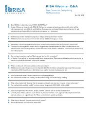
Beamsmodify these properties after you generate them. The procedure for graphically modifying infill beam properties is exactlythe same as discussed in the previous sections.To draw infill beams, click on the Drawing Toolbar to open the Generate Infill Beams dialog. Enter the beam type,material, shape group, redesign rules, orientation for bending, beam spacing, placement orientation, and the bay selectionoption, click Apply and click the bay to be filled. You can also draw a polygon around multiple bays or simply drag a boxaround the bays to be filled. If the placement orientation is referenced to a global angle then no other clicks are required, thenew beams will be shown on screen and will be recorded in the Beams spreadsheet. If the placement orientation isreferenced to a member you must then click the reference member and the new beams will be created. For help on an item,click and then click the item.To Draw Infill Beams1. If there is not a model view already open then click on the <strong>RISA</strong> Toolbar to open a new view and click toturn on the Drawing Toolbar if it is not already displayed.2. If you do not already have existing framed bays, you will need to create them first.3. Click the button and set the beam properties.4. Click Apply to start generating beams by clicking on the bay opening or drawing a box around the bays in which youwant the beams generated. If the placement orientation is referenced to a member, you must then click the referencemember with the left mouse button. The coordinates of the closest grid point or snap point to your cursor aredisplayed in the lower right hand corner.5. To stop drawing click the right mouse button, or press the Esc key.Note• Press CTRL-D to quickly recall the dialog and make changes.• You may also specify or edit beams in the Beams Spreadsheet.• You may undo any mistakes by clicking the Undo button.General Reference Manual 19
Beams• The items in the material and design rules are listed in the same order in which they appear in the Material and DesignRules spreadsheets.For additional advice on this topic, please see the <strong>RISA</strong> News website: www.risanews.com. Type in Search keywords: InfillBeams.Resolve Beam ChoicesThere are occasions where your input infill beam spacing may not perfectly fit the bay selected. In these cases you will bepresented with the Resolve Beam Choices dialog.This dialog allows you to make a manual; choice between the available spacing options, rather than having the programrandomly choose one. For example, if you have a 10' x 10' bay and you ask for an exact spacing of 3 ft, you will be presentedwith the two options:20 <strong>RISA</strong>Floor v6
BeamsThe green lines represent a 3 ft spacing starting from the left hand side, while the blue lines represent a 3 ft spacing startingfrom the right hand side. Rather than assuming one or the other, the program offers you the choice of where you want yourframing located.Choosing Centered in Bay will center the beams in the bay, and split the remaining space evenly on both sides.Modifying Beam PropertiesThere are two ways to modify beams. You may view and edit the beam data in the Beams Spreadsheet. Or, you can use theModify Beams tool of the Beams dialog to graphically modify a possibly large selection of beams. See Beams – PrimaryData for information on the beams and properties themselves.The graphical Beam Modify tool discussed here lets you modify the properties of beams that already exist in your model. Touse this, you will typically specify parameters you want changed then select the beams that you want to modify. You canmodify beams one at a time by selecting the Click to Apply option and then click on the beams you wish to modify. Youmay also modify entire selections of beams by selecting the beams first and then use the Apply to Selected option. SeeGraphic Selection for more on selecting or unselecting portions of your model.To Modify Beams1. If there is not a model view already open then click on the <strong>RISA</strong> Toolbar to open a new view and click toturn on the Drawing Toolbar if it is not already displayed.2. Click the button and select the Modify Properties tab. Set the parameters for the changed beams. Check theUse? Box for the items to apply. For help on an item, click and then click the item.3. You may choose to modify a single beam at a time or an entire selection of beams.To modify a few beams choose Apply Entries by Clicking Items Individually and click Apply. Click on the beamswith the left mouse button.To modify a selection, choose Apply Entries to All Selected Items and click Apply.Note• To modify more beams with different parameters, press CTRL-D to recall the Modify Beams settings.• You may also modify beams in the Beams Spreadsheet.• To relabel beams first sort the Beams spreadsheet into the desired order then select the Tools menu and chooseRelabel Beams.• You may undo any mistakes by clicking the Undo button.The parameters shown are nearly the same as those used to define new beams.General Reference Manual 21
BeamsThe Use? check boxes next to the data fields indicate whether the particular parameter will be used or not when themodification is applied. If the box next to a field is checked, that parameter will be applied to any selected beams. If the boxis NOT checked the parameter will NOT be applied, even if a value is entered in the field. This lets you easily change one ortwo properties on beams without affecting the rest of the properties. Note that if the field is blank and the correspondingUse? box is checked, clicking Apply will have the effect of clearing the data for these fields.Note:• The <strong>RISA</strong>Connection modification options are only available for hot-rolled steel and only work if you also own<strong>RISA</strong>Connection. See the <strong>RISA</strong>Connection Integration topic for more information.Modifying Beam Design ParametersYou can graphically specify the AISC, AISI, NDS and composite design parameters such as unbraced lengths, K factors, andeffective widths. See Hot Rolled Steel - Design, Cold Formed Steel - Design, Wood - Design, Concrete - Design, and HotRolled Steel - Composite Beam Design for information on the design parameters themselves.To do this, you will specify the appropriate beam parameters then select the beams that you want to modify, and then click onthe Apply button. Alternately you can set the parameters and then choose the Click to Apply option, which allows you tothen click on the beams you want modified.To Modify Beam Design Parameters1. If there is not a model view already open then click on the <strong>RISA</strong> Toolbar to open a new view and click toturn on the Drawing Toolbar if it is not already displayed.2. Click the button and select the Modify Design tab. Set the parameters for the beam design. Check the Use? Boxfor the items to apply. For help on an item, click and then click the item.3. You may choose to modify a single beam at a time or an entire selection of beams.To modify a few beams choose Apply Entry by Clicking Items Individually and click Apply. Click on the beamswith the left mouse button.22 <strong>RISA</strong>Floor v6
BeamsTo modify a selection, choose Apply Entries to All Selected Items and click Apply.Note• To modify more beams with different parameters, press CTRL-D to recall the Modify Beams settings.• You may also specify or edit beams in the Beams Design Spreadsheet.• You may undo any mistakes by clicking the Undo button.The Use? check boxes next to the data fields indicate whether the particular parameter will be used or not when themodification is applied. If the box next to a field is checked, that parameter will be applied to any selected beams, if the boxis NOT checked, the parameter will NOT be applied, even if a value is entered in the field. This lets you easily change one ortwo properties on beams without affecting all the rest of the properties. Note that if the field is blank and the correspondingcheck box is checked, clicking Apply will have the effect of clearing the data for these fields.Beams – Primary DataThe Beams Spreadsheet records the properties for the beam elements and may be accessed by selecting Beams on theSpreadsheets menu. The spreadsheet has six tabs: Primary Data, Hot Rolled, Cold Formed, Wood, Concrete, and Detailing.The pull down list at the top of the spreadsheet allows you to toggle between floors.All beams for a particular floor are listed on the Primary Data tab. You may choose the floor from the drop down list at thetop of the spreadsheet. The Hot Rolled, Cold Formed, Wood, and Concrete tabs list only beams that use those materials.The entries for the Beam Primary Data tab are explained below:General Reference Manual 23
BeamsBeam LabelsA unique label may be assigned to all of the beams manually or automatically. You can then refer to the beam by its label.You may relabel beams at any time with the Relabel Beams option on the Tools menu. The label column of the spreadsheetis displayed on all tabs of the spreadsheet.Beam PointsStart Point and End Point list the labels of the start and end points of the beam. See Points for more information aboutpoints.Shape Group & MaterialEnter the shape group and material you wish to use for the beam. You can choose both by clicking on the arrow in the cell.The material pull down list presents materials listed in the Materials spreadsheet. See Material Properties for moreinformation.A Shape Group (also known as a Design List) designates the type of beams that will be used to design and optimize thebeam. Refer to Appendix A - Redesign Lists for more information.Design RulesEnter the set of design rules you wish to use to optimize the design of the beam. You can choose by clicking on the arrow inthe cell. This pull down list is related to the Design Rules spreadsheet. See Design Optimization for more information.FunctionThe Function of a beam may be selected by choosing either 'Lateral' or 'Gravity' from the drop down list. Beams that areindicated as 'Lateral' will be designed for gravity loads in <strong>RISA</strong>Floor and may be optimized for lateral loads (and gravityloads) by <strong>RISA</strong>-3D. See <strong>RISA</strong>-3D Integration for more information.OrientationEnter the orientation you wish to use for the beam – Strong Axis or Weak Axis. You can choose by clicking on the arrow inthe cell.Note• To be sure of a beam’s orientation you can always view the rendered shape of a beam by clicking the button on theWindow toolbar.Start and End ReleasesReleases control the forces that may be resisted by a beam. You may use these to define pinned connections, for simplysupported gravity beams, or fixed connections. To specify beam releases go to the Start Release or End Release field for thebeam and select the condition from the list.Beams Spreadsheet - Detailing DataThe Detailing tab records the detailing data for the beams that are necessary for full 2-way data transfer between <strong>RISA</strong> andsteel detailing packages. For more information on this subject refer to the Help file for the <strong>RISA</strong> CIS/2 Translator which canbe downloaded from our website.24 <strong>RISA</strong>Floor v6
BeamsGeneral Reference Manual 25
Beams - ResultsBeams - ResultsWhen the model is solved, the results are separated into material specific design results and generic results. The generic beamresults are discussed in this section. The material specific design results are discussed in the following sections of the manual:Hot Rolled Steel - Design, Concrete - Design, Cold Formed Steel - Design, and Wood - Design. For information on MemberDetail Reports see the Results section.Single Angle ResultsDepending on whether a single angle has been fully restrained against rotation or not it will either behave about its geometricaxes or its principal axes. This behavior can be controlled by correctly specifying the unbraced lengths for the angle. In thediagram below the z and y axes are the geometric axes. The z' and y' are the principal axes. The y' axis is considered to be theweak axis for principal behavior, and the z' is considered to be the strong axis.The orientation of the shape is defined using the local y and z axes shown in the above diagram, but for principal axisbehavior the bending calculations are done with respect to the y' and z' axes shown (the principal axes). The y' axis is the axisof minimum 'I' and the z' axis is the axis of maximum 'I'. <strong>RISA</strong> calculates the angle "α" and transposes the moments as shownbelow:Mz' = Mz * cos(α) + My * sin(α)My' = -Mz * sin(α) + My * cos(α)Note• If both LcompTop and LcompBot have been set to zero then the angle will behave about its geometric axes andthe member forces and stresses will be displayed relative to the geometric axes. Alternatively, setting the L-torque value to zero will also constrain the single angle to behave about its geometric axes.Beam Deflection ResultsThe Deflection Results Spreadsheet presents the deflections for beam members and may be accessed by selectingDeflection on the Results Menu. The spreadsheet has three tabs: Relative Standard, Relative Alternate, and Absolute.Relative deflections are measured from the deflected end points of the beams. Absolute deflections, however, include thedeflection of the beam end points. The pull down list at the top of the spreadsheet allows you to toggle between floors.General Reference Manual 26
Beams - ResultsThe sign convention is such that positive deflections are downward. The deflections are calculated at 100 locations alongeach beam for each load category and the maximum deflection and deflection ratio are displayed. See for more information.The Beam Label column displays the beam label.The Camber column displays the camber required for the percentage of pre-composite dead load specified in the GlobalParameters. To modify camber requirements see Global Parameters.Note• <strong>RISA</strong>Floor does not perform camber calculations for continuous beams or cantilevers.PreDL and PreDL RatioThese columns display the maximum deflection along the member due to the total, unfactored pre-composite dead load. Thisincludes the deflection due to beam self weight, deck self weight, deck construction DL and pre-composite DL minus theeffect of camber. The PreDL column gives the relative deflection on the beam from its supporting members. The PreDLRatio is the length of the member divided by the maximum PreDL deflection.DL and DL RatioThese columns display the maximum deflection along the member due to total unfactored dead load. This includes thedeflection due to beam self weight, deck self weight, pre-composite DL and post-composite DL minus the effect of beamcamber. The DL column gives the relative deflection on the beam from its supporting members. The DL Ratio is the lengthof the member divided by the maximum DL deflection.LL and LL RatioThese columns display the maximum deflection along the member due to total unfactored live load. This will be due to thesummation of all of the various live load categories. This includes Live Load, Live Load Special, Roof Live Load, SnowLoad and Rain Load. The LL column gives the relative deflection on the beam from its supporting members. The LL Ratio isthe length of the member divided by the maximum LL deflection.Note• Cnstruction live load (LLConst) is not included in the deflection ratio checks. If a category specific deflectionrestriction has been imposed for construction live load then it will be reported on the Relative Alternate tab.The DL+LL and DL+LL RatioThese columns display the maximum deflection along the member due to the sum of total unfactored DL and total unfactoredLL. The DL+LL ratio is calculated as the length of the member divided by the maximum DL+LL deflection.General Reference Manual 27
Beams - ResultsAlternate Deflection DesignThe Relative Alternate tab only displays results when additional categories have been specified in the design rules. Thecategory, relative unfactored displacement, and displacement ratio of these additional requirements are listed. See DesignRules – Deflection for more information.Absolute DeflectionsThe Absolute tab displays the absolute unfactored displacements for the categories described above. Absolute deflectionsinclude the effects of the beam end points.Beam End ReactionsThe End Reactions Spreadsheet records the end reactions for the beam elements and may be accessed by selecting EndReactions on the Results Menu. The pull down list at the top of the spreadsheet allows you to toggle between floors.If “Show Factored End reactions” in Global Parameters is left unchecked, these displayed forces are not factored. If it ischecked, then the displayed forces will have been multiplied by the factors in the load combinations. The sign conventionassigns positive reactions to downward forces. Negative reactions, if they occur, would indicate uplift.The Beam Label column displays the beam label.The End column identifies for which end of the beam the reaction is being given, with the beam start and end on alternatingrows.Note• Moment reactions for fixed end beams can be displayed graphically when using the Design Results labelingoption for beams from the Plot Options. However, these moments are not currently reported in the Beam EndReactions spreadsheet results, or in the End Reactions section of the beam detail report.Dead LoadsThe PreDL column displays the member end reaction due to the pre-composite dead load. This includes the sum of the beamself weight, deck self weight, deck construction dead load and pre-composite dead load.The DL column displays the member end reactions due to the total dead load. This includes the sum of the beam self weight,deck self weight, pre-composite dead load and post-composite dead load.Live LoadsThe LL column displays the member end reaction due to the live load. This includes the sum of the live load and live loadreducible categories. The portion of this value due to Live Load Reducible has already been reduced, thereby resulting in afinal design value which should be appropriate for connection design.28 <strong>RISA</strong>Floor v6
Beams - ResultsRoof LoadsThe Roof column displays the member end reaction due to the roof load. This is the maximum of the following loadcategories: Roof Live Load, Snow Load, Snow Load non-shedding, and Rain Load. The Roof Cat cell displays thecontrolling load category for the roof load end reactions.Max, Min & LCThe Max, Min and LC columns display the maximum and minimum end reactions and the controlling load combination inwhich they occur.Note:• For hot-rolled steel members only load combinations with the "Connection" checkbox checked in the LoadCombinations spreadsheet will be selected. See the Loads - Load Combinations topic for more information.Beam Vibration ResultsVibration calculations are performed for beam members according to the requirements of AISC Design Guide 11: FloorVibrations Due to Human Activity. For information on beam vibration calculations and results, refer to Vibrations - FloorFraming.General Reference Manual 29
Cold Formed Steel - DatabasesCold Formed Steel - DatabasesShapes are organized in the database by manufacturer. Common shapes are supported such as C sections with and withoutlips, Z sections with and without lips, and Hat sections without lips. Each of these shape types may be used as single section,a back to back section, or a face to face section. You may type in the names directly, select shapes from these databases oradd your own shapes.<strong>RISA</strong> currently supports the following common Cold Formed steel databases: AISI 2007, Dale-Incor, Dietrich, Marino-Ware,and SSMA.To Select a Cold Formed Database Shape1. From the Primary Data tab of the Beams or Columns Spreadsheet, move the cursor to the Shape field and click .2. Specify the database and shape type you wish to use and then select from the list of available shapes by clicking on.Custom vs. Manufacturer ShapesYou can enter your own cold formed shapes as well as use those provided in the manufacturer database. When the coldformed database type is selected, you'll notice a "Manufacturer" list box that appears in the Shape Selection dialog. You canspecify a manufacturer or choose “Custom” to select, add or edit your own custom shapes. New shape properties arecalculated using the linear method described in Part I of the AISI code.Database FilesThe cold formed manufacturer shape databases are stored in the file aisidb32.fil, and the custom cold formed shapes arestored in the file aisicust.fil.30 <strong>RISA</strong>Floor v6
Cold Formed Steel - DatabasesTo Add a Database Shape1. On the <strong>RISA</strong> Toolbar click the Edit Shape Database button.2. Select the cold formed tab and set the Manufacturer type to "Custom", then select the shape type you wish to add andclick the Add button.3. Specify a name for the shape and fill in the Basic Properties.4. Click Calc Props to determine the shape properties.Note• Alterations to the shape database are not permanent unless you agree to save them. Changes that are not savedonly remain valid for the current session and will not be present the next time you start <strong>RISA</strong>.• New shapes are added to the bottom of the database.• To delete a shape, specify the database and shape type you wish to delete and then click the Delete button.• To edit a shape, click the Edit button and edit the shape properties. Values can only be manually edited here,nothing will be recalculated. If you wish to have all the values for a shape recalculated, you will need to deletethe shape and then add it again with the new properties. Manufacturer shapes cannot be edited, only customshapes can be edited.Cold Formed Shape TypesThere are five types of shapes. Names for each shape type follow the convention of the manufacturer for each shape. If youknow the shape name, you can type the name directly into the Shape field on the spreadsheets. Alternately you may clickthe button to look up a shape and select it.C sections without lips (CU)For the AISI database, CU shapes are called out by the designation given them in the AISI steel manual. For example, if youwanted a 12" deep unstiffened C section, you'd call it out as 12CU1.25x071. The '12' is the depth, the CU specifies a Csection without lips, the '1.25' is the flange width, and the '071' is the decimal thickness. Other manufacturer databasesgenerally follow similar conventions.General Reference Manual 31
Cold Formed Steel - DatabasesC sections with lips (CS)For the AISI database, CS shapes are called out by the designation given them in the AISI steel manual. Other manufacturerdatabases generally follow similar conventions.Z sections without lips (ZU)For the AISI database, ZU shapes are called out by the designation given them in the AISI steel manual. Other manufacturerdatabases generally follow similar conventions.Z sections with lips (ZS)For the AISI database, ZS shapes are called out by the designation given them in the AISI steel manual. Other manufacturerdatabases generally follow similar conventions.Hat sections without lips (HU)For the AISI database, HU shapes are called out by the designation given them in the AISI steel manual. Other manufacturerdatabases generally follow similar conventions.Double SectionsFor each of the five shape types the selected shape may be used as a standard single section or as a double section. Thechoices for double sections are 'Back to Back' and 'Face to Face'. A typical double section is designated with a "2-" precedingthe shape name and a "-BB" (Back to Back) or "-FF" (Face to Face) following the shape name. For example, a "2-12CU1.25x071-FF" section represents two 12" deep C sections with 1.25" wide flanges and a 0.071" thickness placed face toface.Note• The program currently only performs an analysis of double sections and does not perform a code check of anykind. This may be added into a future revision of the program.32 <strong>RISA</strong>Floor v6
Cold Formed Steel - DesignCold Formed Steel - DesignFull code checking can be performed on standard cold formed steel shapes, based on the following codes:• The 1996 edition of the AISI code with 1999 Supplement (AISI-99 ASD and LRFD)• The 2001 edition of the AISI code (AISI NAS-2001 ASD and LRFD)• The 2001 edition of the Mexican code (CANACERO-2001 ASD and LRFD)• The 2001 edition of the Canadian code (CSA S136-01 LSD)• The 2004 Supplement of the AISI code (AISI NAS-2004 ASD and LRFD)• The 2004 Supplement of the Mexican code (CANACERO-2004 ASD and LRFD)• The 2004 edition of the Canadian code (CSA S136-04 LSD)• The 2007 edition of the AISI code (AISI NAS-2007 ASD and LRFD) including Supplement No.1 (August 09)• The 2007 Supplement of the Mexican code (CANACERO-2004 ASD and LRFD) including Supplement No.1(August 09)• The 2007 edition of the Canadian code (CSA S136-07 LSD)Cold formed shape properties are available in the database and the values are based on the AISI or manufacturer values,whichever is selected (See Cold Formed Steel Database). You may also input your own basic shapes and the properties willbe calculated automatically.Design ParametersThe Cold Formed tab on the Beams Spreadsheet and the Steel/Wood tab on the Columns Spreadsheet record the designparameters for the cold formed steel code checks. These parameters may also be assigned graphically. See Modifying BeamDesign or Modifying Column Design to learn how to do this.These parameters are defined for each cold formed member. The entries are explained below. The pull down list at the top ofthe spreadsheet allows you to toggle between floors.General Reference Manual 33
Cold Formed Steel - DesignLabelYou may assign a unique Label to all of the members. Each label must be unique, so if you try to enter the same label morethan once you will get an error message. The Label field for column members is dictated by the label entry on the ColumnStacks Spreadsheet and may not be edited here. If you would like to edit this entry, you must do so on the Column StacksSpreadsheet.LengthThe beam Length is reported in the second column. This value may not be edited as it is dependent on the beam start andend points listed on the Primary Data tab. It is listed here as a reference for unbraced lengths which are discussed in the nextsection.Unbraced LengthYou may specify unbraced lengths or have <strong>RISA</strong>Floor calculate them for you. The unbraced lengths are Lbyy, Lbzz,Lcomp-top and Lcomp-bot.The Lb values, Lbyy and Lbzz, represent the unbraced length of column members with respect to column type bucklingabout the member's local y and z axes, respectively. They are listed on the Steel/Wood tab of the Columns Spreadsheet.These Lb values are used to calculate KL/r ratios for both directions, which in turn impact the calculation of the axialstrength, Pn. The KL/r ratios gauge the vulnerability of the member to buckling. Refer to Section C4 in Part V of the AISIcode for more information on this. Also, Section C4 lists some limiting values for KL/r. These limiting values are NOTenforced by the program.The Lcomp values, Lcomp-top and Lcomp-bot, are the unbraced lengths of the compression flanges for flange buckling dueto flexure and are listed on the Cold Formed tab of the Beams Spreadsheet and the Steel/Wood tab of the ColumnsSpreadsheet. These may be the same as the Lbyy value, but not necessarily. The Lcomp values are used in the calculation ofbending strength, Mn. Refer to Section C3 in Part V of the AISI code for more information on this. In particular, Lcomp isused in equation C3.1.2.1.-8 as shown in Supplement 1 to the 1999 or the 2001 codes.For continuous beams the moment will reverse such that the top and bottom flanges will be in compression for differentportions of the beam span. Lcomp-top is the unbraced length of the top flange and Lcomp-bot is the unbraced length of thebottom flange.If the Lb and/or Lcomp values are not entered (left blank) for Column Members, the unbraced lengths for each segment ofa physical column or lift will be automatically calculated by <strong>RISA</strong>Floor based on the distances between floor levels and/orsplices. This means that each physical column can have multiple unbraced lengths if the entry is left blank. However, if anumber is entered, <strong>RISA</strong>Floor will use that value for ALL segments of the physical column. Unbraced lengths that have beenset or modified in <strong>RISA</strong>-3D will also be used in <strong>RISA</strong>Floor.When the Lcomp values are left blank for Beam Members, the deck properties and the members framing into the beam willdetermine the unbraced length used by the program and will vary along the length of the beam. This means that each beamcan have multiple unbraced lengths if the entry is left blank. For the top flange, Lcomp-top, the smaller of the deck bracingor member framing distances will be used at each location. For the bottom flange, Lcomp-bot, the full length of the beamwill be used. If a number is entered, <strong>RISA</strong>Floor will use that value for ALL segments of the beam.Note:• For Hat Channel (HU) shape types, the Lcomp-top and Lcomp-bot values only apply to the flanges perpendicular tothe local y axis (please see image below). Therefore, if your loading is applied in the local z direction, these entrieswill not apply. This assumption was made in reference to section C3.1.2.1 of the AISI Specification with Commentarywhose footnote tells us that the limit state of Lateral-Torsional Buckling does not apply to these shapes.34 <strong>RISA</strong>Floor v6
Cold Formed Steel - DesignFor beam members, you can enter the code “Segment” in the unbraced length fields and the length of the longest segmentwill be used. A “segment” is the distance between the joints that are on the beam. For example, suppose you have a beam thatis 20 feet in length, and there are two joints along the beam, one 5 feet from the end and one at 15 feet. An unbraced length of10 feet will be used for the design of the beam. The "segment" code cannot be entered for column members.Note• If the intermediate framing members are considered to brace the bottom flange, then you can enter “segment” forLcomp-bot. When the “segment” command is used ALL intermediate points along the beam are viewed as bracepoints. Therefore, you may have to delete unused or extraneous points.• The Top Flange is defined as the flange corresponding to the positive local y axis for the member.• The calculated unbraced lengths are listed on the Member Detail report.For additional advice on this topic, please see the <strong>RISA</strong> News website: www.risanews.com. Type in Search keywords:Unbraced Lengths.K Factors (Effective Length Factors)The K Factors are also referred to as effective length factors. Kyy is for column type buckling about the member's local y-yaxis and Kzz is for buckling about the local z-z axis.If a value is entered for a K Factor, that value will be used for the segment of the physical column between the current floorlevel or splice above and/or the floor level or splice below. When in <strong>RISA</strong>-3D via <strong>RISA</strong>Floor, the largest K factor entered forany segment of a physical column will be used for the entire physical column. If an entry is not made (left blank), the valuewill internally default to '1' for that column segment. See the AISI code commentary for Section C4 for an explanation ofhow to calculate K Factors.Sway FlagsThe Sway Flags indicate whether the member is to be considered subject to sidesway for bending about its local y and zaxes. The y sway field is for y-y axis bending and the z sway field is for z-z axis bending. Click on the field to check the boxand indicate that the member is subject to sway for that particular direction, or leave the entry blank if the member is bracedagainst sway. These sway flags influence the calculation of the K factors as well as the Cm and Cb factors.Sway Flags are reserved for column members in <strong>RISA</strong>Floor and may be applied to any column segment at any floor level.However, when in <strong>RISA</strong>-3D via <strong>RISA</strong>Floor, if a sway flag is checked for any segment of a physical column, the entirephysical column will be assumed subject to sway. Beam members in <strong>RISA</strong>Floor are assumed to be braced against sway.General Reference Manual 35
Cold Formed Steel - DesignCm - Interactive Bending CoefficientCm Coefficients are described in Section C5 of the AISI code. If these entries are left blank, they will be automaticallycalculated. For column members, each segment of a physical column will receive its own calculated value. However, when in<strong>RISA</strong>-3D via <strong>RISA</strong>Floor, the highest Cm value calculated for a column segment in <strong>RISA</strong>Floor will be used for the entirephysical column in <strong>RISA</strong>-3D.The Cm value is influenced by the sway condition of the member and is dependent on the member's end moments, whichwill change from one load combination to the next, so it may be a good idea to leave these entries blank.Note• The Cm value is currently not used by <strong>RISA</strong>Floor for beam members and is in place for use with the futureimplementation of sloping floor and roof systems. However, Cm values for beam members are "passed" to <strong>RISA</strong>-3D when accessed via the Director button in <strong>RISA</strong>Floor.• In <strong>RISA</strong>Floor, beam members are assumed to be part of a non sway frame and subsequently braced against sway.Cb - Bending CoefficientsFor the cold formed codes, Cb Coefficients are used in the calculation of the nominal flexural strength, Mn. If this entry isleft blank, it will be calculated automatically. For column members, each segment of a physical column will receive its owncalculated value. However, when in <strong>RISA</strong>-3D via <strong>RISA</strong>Floor, the lowest Cb value calculated for a column segment in<strong>RISA</strong>Floor will be used for the entire physical column in <strong>RISA</strong>-3D.R ValueThe R Value for cold formed steel design is described in section C3.1.3 of the AISI code and is used to calculate the momentcapacity of beams that have one flange fastened to deck or sheathing. This value only applies to C or Z members and canvary from 0.4 to 0.7 based on the depth of the member (See table C3.1.3-1 in the AISI Supplement for the actual values).If a value is entered by the user, that value will be used by the program in the moment capacity calculation of the member.There are a number of restrictions that must be met to use this section of the code for moment capacity and the user isresponsible to check that these restrictions are satisfied.Note• If the R value is entered, the program will use section C3.1.3 when performing moment capacity calculations andwill ignore the standard LTB checks from section 3.1.2.• The use of R Values is limited to beam members only in <strong>RISA</strong>Floor.Phi FactorsThe following table provides a list of safety factors (ASD) and resistance factors (LRFD and LSD) being used for differentcodes.Code Ft Fc Fb Fv Wt Wc Wb WvAISI ASD 99 1.67 1.8 1.67 1.5/1.67AISI LRFD 99 0.95 0.85 0.95/0.9 1.0/0.9AISI/Canacero ASD 01 1.67 1.8 1.67 1.6AISI/Canacero LRFD 01 0.9 0.85 0.95/0.9 0.95CSA S136-01 LSD 0.9 0.8 0.9 0.8AISI/Canacero ASD 04 1.67 1.8 1.67 1.6AISI/Canacero LRFD 04 0.9 0.85 0.95/0.9 0.95CSA S136-04 LSD 0.9 0.8 0.9 0.8AISI/Canacero ASD 07 1.67 1.8 1.67 1.6AISI/Canacero LRFD 07 0.95 0.85 0.9 0.9536 <strong>RISA</strong>Floor v6
Cold Formed Steel - DesignDesign ResultsCode Ft Fc Fb Fv Wt Wc Wb WvCSA S136-07 LSD 0.9 0.8 0.9 0.8The Design Results Spreadsheet displays the optimized design results for the beam elements and may be accessed byselecting Designs on the Results menu. The spreadsheet has six tabs: Hot Rolled, Cold Formed, Wood, Steel Products,Wood Products, and Concrete. The pull down list at the top of the spreadsheet allows you to toggle between floors.The Label column lists the beam label.The Size column displays the beam size. When no adequate member could be found from the available shapes list, this fieldwill display the text “not designed”. Consider re-framing, relaxing the design or deflection requirements (see DesignOptimization), or adding more shapes to the available Redesign List (see Appendix A – Redesign Lists).The Explicit column displays "Yes" if the beam has been locked to an explicit beam size by the user. When you have chosena specific shape to override the programs automatic redesign, that beam becomes "locked" and will not be automaticallyredesigned by the program.Note• To "unlock" a beam, you can use the beam – modify tool to assign a shape group. If the model has already beensolved, you may optimize a beam by using the Member Redesign dialog. See Member Redesign for more details.The Material Column displays the material label assigned to the beam.End ReactionsThe Max Start & End Reactions column displays the maximum start and end reactions of the beam for ALL loadcombinations. If "Show Factored End Reactions" in Global Parameters is left unchecked, these displayed forces are notfactored. If it is checked, then the displayed forces will have been multiplied by the factors in the load combinations. Thesign convention assigns positive reactions to downward forces. Negative reactions, if they occur, would indicate uplift.The Min Start & End Reactions column displays the minimum start and end reaction of the beam.Code ChecksThe Code Checks Spreadsheet summarizes the code check results for the beams and may be accessed by selecting CodeChecks on the Results menu. The spreadsheet has four tabs: Hot Rolled, Cold Formed, Wood, and Concrete. The pull downlist at the top of the spreadsheet allows you to toggle between floors.General Reference Manual 37
Cold Formed Steel - DesignThe Label column displays the beam label.The Size column displays the beam size. When no adequate member could be found from the available shapes, this field willdisplay the text "not designed". Consider re-framing, relaxing the design or deflection requirements (see DesignOptimization), or adding more shapes to the available Redesign List (see Appendix A – Redesign Lists).The Explicit column displays "Yes" if the beam has been locked to an explicit beam size by the user. When you have chosena specific shape to override the programs automatic redesign, that beam becomes "locked" and will not be automaticallyredesigned by the program.Note• To "unlock" a beam, you can use the beam – modify tool to assign a shape group. If the model has already beensolved, you may optimize a beam by using the Member Redesign dialog. See Member Redesign for more details.The Material Column displays the material label assigned to the beam.Bending, Shear, and Deflection ChecksThe Bending Check and Shear Check columns display the maximum bending check and shear check calculated by theprogram. This value is equal to the actual bending or shear demand (stress or force) divided by the actually beam resistance(allowable stress or ultimate capacity). You can see the details of these values in the Bending Results or Shear Resultsspreadsheet. This check is calculated at 100 stations along each beam for each load combination and the maximum check isreported.The Deflection Check displays the maximum deflection check. This value is equal to the ratio of actual deflection toallowable deflection. You can see the details of these values in the Deflection Results spreadsheet. This check is calculatedat 100 stations along each beam and the maximum check is reported. See Beam Results - Deflection for more information.The Location columns display the location along the member where the maximum bending, shear, or deflection checkoccurs.The LC column displays the controlling load combination which resulted in the maximum bending or shear check.Deflection checks are based on Load Categories (Dead, Live or DL+LL), not Load Combinations. Therefore, the controllingload Category for deflections is reported in the Cat column.Note• The program currently only performs an analysis of double sections and does not perform a code check of anykind.Shear ResultsThe Shear Results Spreadsheet records the shear results for the beam elements and may be accessed by selecting Shear onthe Results menu. The spreadsheet has four tabs: Hot Rolled, Cold Formed, Wood, and Concrete. The pull down list at thetop of the spreadsheet allows you to toggle between floors.38 <strong>RISA</strong>Floor v6
Cold Formed Steel - DesignThe Label column displays the beam label.The Size column displays the beam size. When no adequate member could be found from the available shapes, this field willdisplay the text “not designed”. When this occurs, consider re-framing, relaxing the design or deflection requirements (seeDesign Optimization), or adding more shapes to the available Redesign List (see Appendix A – Redesign Lists).The Fy column displays the yield strength of the material.Shear Stress and CapacityThe Vn/Om or phi*Vn column displays the calculated allowable shear capacity based on Section C3 of the applicable AISIcode. The Vu column displays the maximum actual shear demand that the member experiences.The Shear Check column displays the maximum shear check. This value is equal to the actual shear demand (force) dividedby the actual beam resistance (ultimate capacity). This shear check is calculated at 100 locations along each beam for eachload combination. The maximum shear stress, its location, and the controlling load combination are reported.The Location column displays the location along the member where the maximum shear check occurs.The LC column displays the controlling load combination which resulted in the maximum shear check.Note• The program currently only performs an analysis of double sections and does not perform a code check of anykind.Bending ResultsThe Bending Results Spreadsheet records the bending results for the beams and may be accessed by selecting Bending onthe Results menu. The spreadsheet has four tabs: Hot Rolled, Cold Formed, Wood, and Concrete. The pull down list at thetop of the spreadsheet allows you to toggle between floors.The Label column displays the beam label.General Reference Manual 39
Cold Formed Steel - DesignThe Size column displays the beam size. When no adequate member could be found from the available shapes, this field willdisplay the text “not designed”. When this occurs, consider re-framing, relaxing the design or deflection requirements (seeDesign Optimization), or adding more shapes to the available Redesign List (see Appendix A – Redesign Lists).The Fy column displays the yield strength of the material.Unbraced LengthsThe Lb top and Lb bottom columns display the unbraced lengths associated with the controlling bending check. SeeUnbraced Lengths for more information on how these values are calculated.Steel Design CoefficientsThe Cb and Cm columns display the bending coefficients associated with the controlling bending check. More informationon how these values are calculated was presented previously in this chapter.Bending Stress and CapacityThe Mn/Om or phi*Mn column displays the calculated allowable bending moment capacity based on Section C3 of theapplicable AISI code. The Mu column displays the maximum actual bending moment demand that the member experiences.The sign convention is defined so that positive bending will result in tension in the bottom fiber.The Bending Check column displays the maximum bending check calculated by the program. This check is equal to theactual demand (bending moment) divided by the beam resistance (moment capacity). This bending check is calculated at 100locations along each beam for each load combination and the maximum demand (moment), the location, and the controllingload combination are reported.The Location column displays the location along the member where the maximum bending check occurs.The LC column displays the controlling load combination which resulted in the maximum bending check.The Equation column displays the code equation that controlled in the calculation of the bending check.Note• The program currently only performs an analysis of double sections and does not perform a code check of anykind.Column ResultsThe Column Results Spreadsheet summarizes the code check results and records the design results for columns and may beaccessed by selecting Column Results on the Results menu. The spreadsheet has four tabs: Hot Rolled, Cold Formed,Wood, and Concrete.The Stack column displays the column stack label.The Lift column displays the lift number for the physical column. Lift No. 1 is the lowermost physical column in a stack andthe lifts are numbered sequentially moving up the column stack.The Shape column displays the physical column size. When no adequate member could be found from the available shapes,this field will display the text “not designed”. Consider re-framing, relaxing the design or deflection requirements (seeDesign Optimization), or adding more shapes to the available Redesign List (see Appendix A – Redesign Lists).40 <strong>RISA</strong>Floor v6
Cold Formed Steel - DesignCode ChecksThe Code Check column displays the maximum combined axial and bending check calculated by the program. This value isequal to the actual combined axial and bending demand (stress or force) divided by the actually column resistance (allowablestress or ultimate capacity). You can see the details of this value in the subsequent Axial Resistance (Pn/Om or phi*Pn andTn/Om or phi*Tn) and Flexural Resistance (Mnyy/Om & Mnzz/Om or phi*Mnyy & phi*Mnzz) columns of thisspreadsheet. This check is calculated at 100 stations along each physical column for each load combination and the maximumcheck is reported.The Shear Check column displays the maximum shear check calculated by the program. This value is equal to the actualshear demand (stress or force) divided by the actual column resistance (allowable stress or ultimate capacity). This check iscalculated at 100 stations along each column for each load combination and the maximum check is reported.The Elev columns display the absolute elevation along the column stack where the maximum code check occurs.The LC column displays the controlling load combination which produced the maximum code check and/or shear check.The Dir column displays the column local axis along which the maximum shear check occurs.Note• The program currently only performs an analysis of double sections and does not perform a code check of anykind.Column Stress and CapacityThe Pn/Om (ASD) or phi*Pn (LRFD) column displays the calculated allowable compressive capacity based on Section C4of the applicable AISI code.The Tn/Om (ASD) or phi*Tn (LRFD) column displays the calculated allowable tensile capacity based on Section C2 of theapplicable AISI code.The Mnyy/Om and Mnzz/Om (ASD) or phi*Mnyy and phi*Mnzz (LRFD) columns display the calculated allowablebending moment capacity based on Section C3 of the applicable AISI code.The AISI Eqn column displays the code equation used in the calculation of the controlling code check.Steel Design CoefficientsThe Cb, Cmyy, and Cmzz columns display the bending coefficients associated with the controlling bending check. Moreinformation on how these values are calculated was presented previously in this chapter.Assumptions and LimitationsFor all shape types, it is assumed that the transverse load on the member is occurring through the member's shear center. Thismeans secondary torsional moments that may occur if the load is not applied through the shear center are not considered.Iterations for the effective section modulus (Se and Sc) are ended when a difference less than 1% is achieved in the neutralaxis distance calculation with a maximum of 5 iterations. Holes in sections are not considered in the shear strengthcalculations or for effective width calculations. Deflections are based on the full section properties, not the effective sectionproperties.Lt is assumed to be the smaller of Lbyy or Lcomp. Torsional warping effects are not included. Web crippling is notconsidered.Kt in section C3.1.2.1 is assumed to be 1.0. All conditions listed for the use of C3.1.3-1 are assumed satisfied. Section C3.1.4is not considered in the calculation of Mn. Effects of shear stiffeners for section C3.2.1 are not considered. Only strong axisbending and strong axis shear are considered for equation C3.3.1 (combined bending and shear).Section C4.4 is not considered in the calculation of the axial strength at this time.General Reference Manual 41
Cold Formed Steel - DesignZ Shapes – The bracing length in Lbyy is assumed to brace the minor principal axis. Z sections in compression are assumedto buckle in Euler buckling about their weakest principal axis. The value of r min is used rather than the geometric r x and r yvalues.H Shapes – Hat sections in bending about the y-y axis such that the brims are in compression are assumed braced such thatthe brims cannot each fail in lateral torsional buckling independently.Double Sections - The program currently only performs an analysis of double sections and does not perform a code check ofany kind.Slenderness Limitations - The w/t limits of Section B1.1 are enforced. However, the shear lag effects (section B1.1c) arenot enforced.Special MessagesAISI Code Check Not CalculatedThis message is displayed when the member is not defined with a database shape, or is defined as a double section, or a steelcode is not specified on the Global Parameters, or no units were specified.Can't do code check, stiffener D/w > 0.8 (Sect. B4.2)The ratio D/w exceeds the limiting criteria listed in Section B4.2 for simple lip stiffeners. (“D” and “w” are length of thestiffener and the flat length of the flange as defined in B4.2)Stiffener angle gamma is < 40 or > 140 (Sect. B4.2)The angle (gamma) for a simple lip stiffener must be greater or equal to 40 degrees or less than or equal to 140 degrees perthe criteria in section B4.2. The angle gamma for this shape is outside this range.Can't do code check, flange w/t > limit (Sect. B1.1)The ratio w/t exceeds the limiting criteria listed in section B1.1 for flanges. A value of 60 is used per the AISI code forunstiffened elements and elements stiffened with simple lips.Can't do code check, web h/t > 200 (Sect. B1.2)The ratio h/t exceeds the limiting criteria listed in section B1.2 for webs. The program currently considers all webs asunreinforced, so a value of 200 is used as the limit.42 <strong>RISA</strong>Floor v6
ColumnsColumnsBoth columns and walls may be used as supports for beams, and both transfer load from floor to floor, and ultimately to thefoundation. Column design is available for Hot Rolled Steel, Cold Formed Steel, Wood, and Concrete. Automatic live loadreductions for columns is available as well.Columns may be defined as either Gravity columns or Lateral columns. Gravity columns are analyzed and designedcompletely within <strong>RISA</strong>Floor for gravity/vertical loads only. Lateral columns function as part of the lateral load resistingsystem which can be analyzed and designed in <strong>RISA</strong>-3D for the combined gravity/vertical loads as well as lateral forces. See<strong>RISA</strong>-3D Integration for more information on lateral system design.Columns can be specified as Hot Rolled, Cold Formed, Wood, or Concrete. The shapes available for each are listed below:DesignationHot RolledCold FormedWoodConcreteShape GroupWide FlangeTubePipeChannelSingle AngleDouble AngleW_TeeWF 8WF 10WF 12WF 14HSS PipeSquare TubeCUCSZUZSHURectangularRectangular DoubleRectangular TripleRoundRectangularRoundRectangular_MMRound_MMAny available material listed in the Materials Spreadsheet can be assigned to a column (See Material Properties). Allcolumn shapes and material properties may be defined graphically as you draw or later as a modification to the columns.Refer to the next two sections for more information.General Reference Manual 43
ColumnsColumn / Beam InteractionColumns may be modeled as vertical supports with no rotational stiffness, or as vertical supports with a rotational stiffnessbased on their height, section properties, and orientation. Refer to Global Parameters - Solution for more information.Drawing ColumnsNew columns may be drawn in a model view window using a Project Grid, Drawing Grid, or previously entered pointlocations. You can set all of the column properties before drawing them or you can modify the properties afterwards.Modifying properties is discussed in the next section.To draw columns, click on the Drawing Toolbar to open the Draw Columns dialog. Enter the column type, material,shape group, function, and orientation followed by the drawing option you wish to use. By selecting the 'Click or BoxLocations for Columns' option you will click or box existing grids or points after clicking on Apply. Clicking on a gridintersection or point defines a single column. By boxing multiple grid intersections you can define multiple columns at once.Choosing the 'Offset Columns From the Click/Box Locations' option allows you to define a horizontal and/or vertical offsetor an angular offset from the selected grid intersections or points. As you draw, the coordinates of the nearest grid point areshown in the status bar in the lower right corner. The new columns will be shown on screen and will be recorded in theColumns and Column Stacks Spreadsheets. For help on an item, click and then click the item.To Draw Columns1. If there is not a model view already open, click on the <strong>RISA</strong> Toolbar to open a new view and click to turnon the Drawing Toolbar if it is not already displayed.44 <strong>RISA</strong>Floor v6
Columns2. If you do not already have a grid or existing point locations available you will need to create them first.3. Click the button and set the Column Shape, Function, Orientation, and Drawing Options. For help on an item,click and then click the item.4. Click Apply to start drawing columns by clicking or boxing grid intersections and/or points with the left mousebutton. The coordinates of the closest grid or point to your cursor are displayed in the status bar on the lower righthand corner of your screen.5. To stop drawing altogether click the right mouse button, or press the Esc key.Note• Press CTRL-D to quickly recall the dialog and make changes.• You may also specify or edit columns in the Columns or Column Stacks Spreadsheet.• Undo any mistakes by clicking the Undo button.Modifying Column PropertiesTo modify column properties you may edit the column data in the Columns and/or Column Stacks Spreadsheets. Use theModify Properties tab of the Columns dialog to graphically modify a large selection of columns at once. See ColumnPrimary Data for specific information on the column properties.The graphical Modify Properties tool lets you modify the properties of columns that already exist in your model. To usethis, you will typically specify the parameters you want to change and then select the columns that you want to modify. Youcan modify columns one at a time by selecting the Click to Apply option and then clicking on the columns you wish tomodify. You may also modify entire selections of columns by previously selecting the columns and using the Apply toSelected option. See Graphic Selection for more information on selecting.To Modify Column Properties1. If there is not a model view already open, click on the <strong>RISA</strong> Toolbar to open a new view and click to turnon the Drawing Toolbar if it is not already displayed.2. Click the button and select the Modify Properties tab. Set the parameters for the columns you wish to modify.Check the Use? box for each of the parameters you wish to apply.3. To modify columns one at a time choose Apply Entries by Clicking Items Individually and click Apply. Click onthe columns with the left mouse button. To modify a selection of columns, choose Apply Entries to All SelectedItems and click Apply.Note• To modify more columns with different parameters, press CTRL-D to recall the Modify Properties settings.• You may also modify columns in the Columns or Column Stacks Spreadsheets.• Undo any mistakes by clicking the Undo button.The parameters shown are the same as those used to define new columns. For help on an item, clickitem.and then click theGeneral Reference Manual 45
ColumnsThe Use? check boxes next to the data fields indicate whether the particular parameter will be used or not when themodification is applied. If the box next to a field is checked, that parameter will be applied to any selected columns, if thebox is NOT checked, the parameter will NOT be applied, even if a value is entered in the field. This lets you easily changeone or two properties on columns without affecting all the rest of the properties. Note that if the field is blank and thecorresponding Use? box is checked, clicking Apply will have the effect of clearing the data for these fields.Modifying Column Design ParametersTo modify column design parameters you may edit the column data in the Columns Spreadsheet. Use the Modify Designtab of the Columns dialog to graphically modify a large selection of columns at once. See Columns Spreadsheet for specificinformation on the column properties.The graphical Modify Design tool lets you modify the design parameters of columns that already exist in your model. Touse this, you will typically specify the parameters you want to change and then select the columns that you want to modify.You can modify columns one at a time by selecting the Click to Apply option and then clicking on the columns you wish tomodify. You may also modify entire selections of columns by previously selecting the columns and using the Apply toSelected option. See Graphic Selection for more information on selecting.To Modify Column Design Parameters1. If there is not a model view already open, click on the <strong>RISA</strong> Toolbar to open a new view and click to turnon the Drawing Toolbar if it is not already displayed.2. Click the button and select the Modify Design tab. Set the design parameters for the columns you wish tomodify. Check the Use? box for each of the parameters you wish to apply.46 <strong>RISA</strong>Floor v6
ColumnsNote3. To modify columns one at a time choose Apply Entries by Clicking Items Individually and click Apply. Click onthe columns with the left mouse button. To modify a selection of columns, choose Apply Entries to All SelectedItems and click Apply.• To modify more columns with different parameters, press CTRL-D to recall the Modify Properties settings.• You may also modify column design parameters in the Columns Spreadsheet.• Undo any mistakes by clicking the Undo button.The Use? check boxes next to the data fields indicate whether the particular parameter will be used or not when themodification is applied. If the box next to a field is checked, that parameter will be applied to any selected columns, if thebox is NOT checked, the parameter will NOT be applied, even if a value is entered in the field. This lets you easily changeone or two properties on columns without affecting all the rest of the properties. Note that if the field is blank and thecorresponding Use? box is checked, clicking Apply will have the effect of clearing the data for these fields.Column Stacks and Physical ColumnsEach column modeled in <strong>RISA</strong>Floor is considered part of a Column Stack which occupies a particular "plan" location withinthe building model. Column Stacks consist of numbered Column Lifts or Physical Columns. A physical column or columnlift may be continuous through one or more floor levels and are defined by Splice locations within the column stack. ColumnStacks and Physical Column Lifts are defined on the Column Stacks Spreadsheet.Column Splices separate one physical column or column lift from the next within a column stack and can be defined asMoment Splices or Shear Splices. Moment Splices transfer both moment and shear from one physical column to the next.Shear Splices transfer only shear forces from one physical column to the next. Column Splices and locations may be assignedon the Columns Spreadsheet or the Floors Spreadsheet (defaults).General Reference Manual 47
ColumnsColumns may also be defined with Parapet extensions beyond the uppermost floor level. Parapets can only be applied tophysical columns occurring along the perimeter of a deck/slab area. Parapet Heights are defined on the ColumnsSpreadsheet.ExampleA particular column stack in a five story building consists of three column lifts or physical columns stacked one on top of theother. The column stack is tied to a particular plan location in building, regardless of elevation, and in this case occurs alongthe perimeter of the building.• Column Lift No. 1 is the lowermost physical column in the column stack and begins at the base elevation of thebuilding and continues vertically to a moment splice whose elevation is defined by a distance measured 10 feet belowfloor level three.• Column Lift No. 2 begins at the splice defining the top of Column Lift No. 1 (10 feet below floor level three) andcontinues vertically to a moment splice whose elevation is defined by a distance measured 10 feet below floor levelfive (the roof in this case).• The uppermost physical column, Column Lift No. 3, begins 10 feet below floor level five and continues vertically to aparapet height measured 3 feet above floor level five (roof). The definition of a parapet is only allowed because thecolumn is on the perimeter of the building.For additional advice on this topic, please see the <strong>RISA</strong> News website: www.risanews.com. Type in Search keywords:Column Splices.Columns SpreadsheetThe Columns Spreadsheet contains all column input data, including primary data and material specific design parameters,and is floor level specific. The Floor Level may be selected from the pull down list just above the spreadsheet.48 <strong>RISA</strong>Floor v6
ColumnsPrimary DataThe Column Primary Data tab of the Columns Spreadsheet records the properties for the column elements and may beaccessed by selecting Columns on the Spreadsheets menu. For information on the Steel/Wood and Concrete tabs, pleaserefer to the Hot Rolled Steel - Design, Cold Formed Steel - Design, Wood - Design, and Concrete - Design sections.The entries for the Column Primary Data are explained below:LabelEach column is assigned a label based on the corresponding Stack Label from the Column Stacks Spreadsheet. That stacklabel is repeated here on the Columns Spreadsheet with an extension, "_L#", that indicates the lift number for the particularcolumn. The label field may not be edited on this spreadsheet but the stack label may be edited on the Column StacksSpreadsheet.PointThe column location is defined by a point in the plane of the floor. These points are created automatically as you draw thecolumns.Shape & MaterialEnter the Shape Group and Material you wish to use for the column. You can choose both by clicking on the arrow in thecell. The material pull down list corresponds to the Materials Spreadsheet. For more information, see Design Optimization- Design Lists or Material Properties for more information. Any entry or editing in these cells will also apply to the Shapeand Material entries on the Column Stacks Spreadsheet.FunctionEnter the function you wish to use for the column – Gravity or Lateral. You can choose by clicking on the pull down list inthe cell. Any entry or editing in this cell will also apply to the Function entry on the Column Stacks Spreadsheet.Angle<strong>RISA</strong>Floor uses two methods to explicitly set the orientation of a column. The first is by setting the angle of rotation for thecolumn about vertical global axis. Use the Angle (deg) entry to enter the rotation angle you wish to use for the column. Ifthe entry is left blank or an angle of “0” is entered, the column is oriented so that the web is "vertical" or "north/south" in theplan view. The second orientation method is defined by the Orientation Point as described below.Orientation PointThe second method to explicitly define the orientation of a column is by specifying an Orientation Point for the column.When used, this orientation point and the column point form a line that defines the orientation of the column web.Note• You can combine the Angle (deg) and Orientation Point to rotate the column with respect to its orientation point.General Reference Manual 49
ColumnsSpliceThe Splice check box indicates whether there is a splice point in the column stack between the current floor level and thefloor level below. The Splice check box will automatically be checked at the lowest floor level of each column stack,indicating the boundary condition of the column base.Note• The <strong>RISA</strong>-3D Boundary conditions at the bottom of a column will be initially set to perfectly pinned or perfectlyfixed based on the splice type in <strong>RISA</strong>Floor. However, after the initial creation of the 3D model, the splice type is nolonger linked to the 3D and it is the user's responsibility to update their boundary conditions to reflect any changes tothe base fixity that are initiated in <strong>RISA</strong>Floor. For additional advice on this topic, please see the <strong>RISA</strong> News website:www.risanews.com. Type in Search keywords: Column Boundary Conditions.Distance Below (Splice Location)The Distance Below entry indicates the dimension to a splice located between the current floor level and the floor levelbelow. If the splice check box is checked, the splice elevation will default to the dimension defined in the Splice DistanceBelow column of the Floors Spreadsheet for the current floor level. If you wish to override the default splice dimensiondefined on the Floors Spreadsheet you may do so by entering an explicit value here. These entries can also be edited via theBot El. and Top El. entries on the Column Stacks Spreadsheet.It is not possible to enter a negative dimension for the splice location as all entered values are considered as absolute values.If you would like to define a splice above the current floor level, you will need to enter the splice on the floor level above.The appropriate units are listed at the top of the column.In the bottom column of a given column stack the Distance Below also defines the distance below the current floor elevationto the base of the column.Note that in models with sloped floors, the distance below is always taken from the floor elevation regardless of the topelevation of a column.For additional advice on this topic, please see the <strong>RISA</strong> News website: www.risanews.com. Type in Search keywords:Building on a Hill.Splice TypeThe Splice Type entry defines the splice as either a Moment splice which will transfer moment and shear between columnlifts in the stack or a Shear splice which will only transfer shear between lifts. If the splice check box is checked, the splicetype will default to the type defined in the Splice Type column of the Floors Spreadsheet for the current floor level. If youwish to override the default splice type you may do so by selecting a type from the pull down list in the cell.Parapet HeightIf the upper most lift of a column stack exists along the perimeter of a slab/deck, the user may assign a Parapet Height tothat lift indicating the dimension to the top of the column with respect to the current floor level. This "column extension"will be included in the floor tributary mass or area for seismic and wind load generation respectively. The default parapetheight for all floor levels is zero. It is not possible to input a negative dimension for the parapet height. The appropriate unitsare listed at the top of the column.Columns Spreadsheet - Detailing DataThe Detailing tab records the detailing data for the columns that are necessary for full 2-way data transfer between <strong>RISA</strong> andsteel detailing packages. For more information on this subject refer to the Help file for the <strong>RISA</strong> CIS/2 Translator which canbe downloaded from our website.50 <strong>RISA</strong>Floor v6
ColumnsColumn Stacks SpreadsheetThe Column Stacks Spreadsheet contains summary information for all column stacks within the building model and may beaccessed by selecting Column Stacks on the Spreadsheets menu. When a column is drawn in <strong>RISA</strong>Floor, or added to theColumns Spreadsheet, a Column Stack is automatically generated in the Column Stacks Spreadsheet.The entries for the Column Stacks Spreadsheet are explained below:Stack LabelWhen a column stack is created in <strong>RISA</strong>Floor, a Stack Label is automatically generated containing the column stack numberand the corresponding project grid line intersection, CS1 (A-1) for example. You may overwrite this assigned label with aunique label of your own if you so choose. However, each label must be unique, so if the same label is entered more thanonce an error message will be displayed.Project GridThe values listed indicate the project grid lines on which the column stack is located. These values are not available forediting in this spreadsheet but may be adjusted via the Label entries on the Project Grid Spreadsheet. If a column stack isnot located on a project grid line in a particular direction a "?" will be used in place of a project grid line. If a project gridline is added at the column stack location at a later time, the Project Grid value will automatically be updated to reflect thenew project grid line.Column Stack CoordinatesThe column stack coordinates, Z and X, contain the coordinates of the Points in the horizontal and vertical directions,respectively, that define the location of the column stack. These values represent the offsets of the Points from the origin ofthe global coordinate system (0, 0) and are not available for editing in this spreadsheet but may be adjusted via the entries onthe Point Locations Spreadsheet. The appropriate units are listed at the top of each column.Lift NumberEach physical column within a column stack is assigned a Lift Number based on its location within the column stack. LiftNo. "1" is assigned to the lowermost physical column within a column stack with Lift No. "2" assigned to the next physicalcolumn and so on, ascending from the bottom of the column stack to the top. These values are not available for editing.Note• There may be a "gap" in a column stack where no column occurs in the building plan at certain floor levels. The liftswill still be numbered sequentially from bottom to top. If the "gap" is later filled, the new physical column will mergeGeneral Reference Manual 51
Columnswith the column below unless an additional splice is added to the column stack. In which case, the column lifts willautomatically be renumbered from bottom to top in order to account for the new lift and maintain sequentialnumbering.Lift LengthThe Length of each physical column or "lift" is listed here. This is the length of the column from the column base to a spliceor top of column, or from splice to splice, or splice to top of column, depending on the position of the lift within the columnstack. These values may be editing in two ways. The first is by editing the Bottom and Top Elevation entries that follow inthe Column Stacks Spreadsheet and the second is via the Distance Below entries on the Column Primary Data tab of theColumns Spreadsheet.Bottom/Top ElevationThe elevation of the bottom and top of each lift, Bot El. and Top El. respectively, are listed here with respect to the baseelevation of the model. These elevations are determined by the Distance Below entries as defined on the Column PrimaryData tab of the Columns Spreadsheet. These elevation entries may be edited and will subsequently update the appropriateentries in this and other spreadsheets.Shape & MaterialEnter the Shape Group and Material you wish to use for the column. You can choose both by clicking on the arrow in thecell. The material pull down list corresponds to the Materials Spreadsheet. See Design Optimization - Design Lists orMaterial Properties for more information. Any entry or editing in these cells will also apply to the Shape and Materialentries on the Columns Spreadsheet.FunctionEnter the function you wish to use for the column – Gravity or Lateral. You can choose by clicking on the pull down list inthe cell. Any entry or editing in this cell will also apply to the Function entry on the Columns Spreadsheet.Design RulesA Design Rule may be applied to each lift of a column stack by making a selection from the pull down list in this cell. Theavailable entries in the pull down list are created on the Design Rules Spreadsheet. For more information see DesignOptimization - Design Rules.Rebar LayoutsFor concrete columns, the Flexural Layout and Shear Layout entries may be used to assign a custom rebar layout to eachlift of a column stack. A custom rebar layout must be used if the user would like to take advantage of bundled bars, multiplelayers or reinforcement, or an unequal number of bars per face.Custom rebar layouts are created in the Rebar Layout Database and may be selected from the pull down list in thisspreadsheet once they have been created. If Optimize is selected from the pull down list, <strong>RISA</strong>Floor will perform the designand select the appropriate reinforcement for the column lift based on the selected design rule. The program will design for anequal number of bars in each face of a rectangular column (a minimum of four (4) bars will be used in circular columnsections) and may vary that reinforcing based on ACI minimums and maximums and the moment and shear demand at eachsection along the span. If the material used for a column lift is not a concrete material, the entry will default to N/A.See the Concrete Database section and the Rebar Layout Database for more information.Column Stack ManagerThe Column Stack Manager may be accessed from a model view by double-any column. This window allows for thedisplay and editing of the entire column stack. It is particularly useful for assigning or moving splices.52 <strong>RISA</strong>Floor v6
ColumnsDisplay and Display ControlsThe column stack manager will display the entire height of the column stack. The Label and the Color Basis of the windowcan be modified by selecting the appropriate setting using the drop down menus. Click Apply to accept any display changes.The column display view on the left is interactive. If the user clicks on the column within the display window, the assignedcolumn properties will be displayed in the text boxes on the right hand side. This is useful for confirming design propertieson a lift by lift or floor by floor basis.In the upper left hand corner of the column stack display window, there exists a number of icons that allow the user to editthe column and column splice data. These allow the user to Add, Delete, or Move a column splice. Similarly, the user maydelete an entire column lift if desired. The last icon controls the increment at which a splice can be moved.Note• When moving a splice it is only possible to move it within the height of the existing floor level. If the splice needs tobe moved to a different level, then it should be deleted and a new splice added at the appropriate location.• Moment splices are indicated by displaying a red diamond shape at the splice location.• Shear splices are indicated by displaying a green circle at the splice location.General Reference Manual 53
Columns• The lowest level of the column splice indicates the boundary condition at the bottom of the column.Lift PropertiesIn display mode, the Lift Properties section displays the start and ending point of the lift along with all of the basic liftproperties. The starting and ending distance are onlyIn modify mode, the user can choose to modify column lifts one at a time by choose Apply Entries by Clicking ItemsIndividually and click Apply. Click on the lift with the left mouse button. To modify all of the displayed columns, chooseApply Entries to All Lifts and click Apply.The Use? check boxes next to the data fields indicate whether the particular parameter will be used or not when themodification is applied. If the box next to a field is checked, that parameter will be applied when the Apply button is pressed.If the box is NOT checked, the parameter will NOT be applied, even if a value is entered in the field. This lets you easilychange one or two properties on a lift without affecting all the rest of the properties.Note• When moving a splice it is only possible to move it within the height of the existing floor level. If the splice needs tobe moved to a different level, then it should be deleted and a new splice added at the appropriate location.Design PropertiesIn display mode, the Design Properties section displays the current floor level along with all of the design parametersassociated with this floor level.In modify mode, the user can choose to modify column properties one floor at a time by choose Apply Entries by ClickingItems Individually and click Apply. Click on the floor, or slightly below it with the left mouse button. To modify all of thedisplayed floor levels, choose Apply Entries to All Lifts and click Apply.The Use? check boxes next to the data fields indicate whether the particular parameter will be used or not when themodification is applied. If the box next to a field is checked, that parameter will be applied when the Apply button is pressed.If the box is NOT checked, the parameter will NOT be applied, even if a value is entered in the field. This lets you easilychange one or two properties on a lift without affecting all the rest of the properties. Note that if the field is blank and thecorresponding Use? box is checked, clicking Apply will have the effect of clearing the data for these fields.54 <strong>RISA</strong>Floor v6
Columns - ResultsColumns - ResultsWhen the model is solved the results are separated into material-specific design results and general results. The generalcolumn results are discussed in this section. The material-specific design results are discussed in the following sections of themanual: Hot Rolled Steel - Design, Concrete - Design, Cold Formed Steel - Design, and Wood - Design. For information onMember Detail Reports see the Results section.Column Forces SpreadsheetThe Column Forces Spreadsheet records the forces and moments in physical columns at each floor level and splicelocation. This spreadsheet may be accessed by selecting Column Forces from the Results Menu.The pull down list at the top of the spreadsheet allows you to toggle between various column forces or moments. The choicesavailable are Axial Force, Shear z-z, Shear y-y, Moment z-z (Top), Moment y-y (Top), Moment z-z (Bot), and Momenty-y (Bot).The spreadsheet has three tabs: Dead & Other Load, Floor Live Load, and Roof Load.Dead & Other Load TabThe Dead & Other Load tab displays the dead load category forces and moments for physical columns. For moreinformation on load categories, see Loads - Load Types. The results displayed on this tab are explained below.The Column Stack entry displays the column stack label. The parentheses note the gridlines of your column. If your columnis only on a single grid line you will get (Grid-). If your column is not on a gridline at all you will get (?-?) or (na).The Lift No. column displays the lift number for the physical column. Lift No. 1 is the lowermost physical column in a stackand the lifts are numbered sequentially moving up the column stack.The Floor Label column displays the floor levels through which each column lift passes. Splice locations between floorlevels are also listed and are indicated by a '+' symbol prior to the floor label. An entry of '+3rd Floor' indicates that there is asplice in the column stack above the 3rd Floor.The Coordinates entry displays the plan coordinates of the column stack and is only listed on rows where the column stacklabel is shown.The Max Base Reactions column records the cumulative forces and/or moments in a physical column lift at the base due tothe load categories DL, OL1, OL2, OL3, OL4, LL, LLS, RLL, SL, SLN, and RL, included in the controlling loadcombination. This value takes into account the live load reduction factors as well as the Load Factors for the controlling loadcombination.The Max Base Reaction LC column displays the load combination that was used to find the Max Base Reaction.The DLPre and DL columns record the cumulative dead load category forces and/or moments in a column lift at the floorlevel indicated. The forces and moments shown include the load accumulated in the column lift at that floor level in additionto the load accumulated in the floor levels above.General Reference Manual 55
Columns - ResultsThe OL1, OL2, OL3, and OL4 columns record the cumulative dead load category forces and/or moments in a column lift atthe floor level indicated. The forces and moments shown include the load accumulated in the column lift at that floor level inaddition to the load accumulated in the floor levels above.Floor Live Load TabThe Floor Live Load tab displays the floor live load category forces and moments for physical columns. For moreinformation on load categories, see Loads. The results displayed on this tab are explained below.The Column Stack entry displays the column stack label.The Lift No. column displays the lift number for the physical column. Lift No. 1 is the lowermost physical column in a stackand the lifts are numbered sequentially moving up the column stack.The Floor Label column displays the floor levels through which each column lift passes. Splice locations between floorlevels are also listed and are indicated by a '+' symbol prior to the floor label. An entry of '+3rd Floor' indicates that there is asplice in the column stack above the 3rd Floor.The Coordinates entry displays the plan coordinates of the column stack and is only listed on rows where the column stacklabel is shown.The Reducible Area column records the cumulative floor area eligible for live load reduction that is tributary to the columnlift at the floor level indicated. The area shown includes the area accumulated in the column lift at that floor level in additionto the area accumulated in the floor levels above.The LL Reduce and LLS Reduce columns display the floor live load reduction factors applicable to the column lift at thefloor level indicated. These reduction factors are calculated based on the values listed in the 'Reducible Area' column of thespreadsheet.The LL (unreduced) and LLS (unreduced) columns record the cumulative Reducible floor live load category forces and/ormoments in a column lift at the floor level indicated. The forces and moments shown include the load accumulated in thecolumn lift at that floor level in addition to the load accumulated in the floor levels above.Note• The Reducible floor live load category forces and/or moments shown have NOT been reduced by the applicablereduction factors listed in the spreadsheet.The NonReduce LL and NonReduce LLS columns record the cumulative Non-Reducible floor live load category forcesand/or moments in a column lift at the floor level indicated. The forces and moments shown include the load accumulated inthe column lift at that floor level in addition to the load accumulated in the floor levels above.Roof Load TabThe Roof Load tab displays the roof load category forces and moments for physical columns. For more information on loadcategories, see Loads. The results displayed on this tab are explained below.56 <strong>RISA</strong>Floor v6
Columns - ResultsThe Column Stack entry displays the column stack label.The Lift No. column displays the lift number for the physical column. Lift No. 1 is the lowermost physical column in a stackand the lifts are numbered sequentially moving up the column stack.The Floor Label column displays the floor levels through which each column lift passes. Splice locations between floorlevels are also listed and are indicated by a '+' symbol prior to the floor label. An entry of '+3rd Floor' indicates that there is asplice in the column stack above the 3rd Floor.The Coordinates entry displays the plan coordinates of the column stack and is only listed on rows where the column stacklabel is shown.The Reducible Area column records the cumulative roof area eligible for live load reduction that is tributary to the columnlift at the floor level indicated. The area shown includes the area accumulated in the column lift at that floor level in additionto the area accumulated in the floor levels above.The RLL Reduce column displays the roof live load reduction factors applicable to the column lift at the floor levelindicated. These reduction factors are calculated based on the values listed in the 'Reducible Area' column of the spreadsheet.The RLL (unreduced) column records the cumulative Reducible roof live load category forces and/or moments in a columnlift at the floor level indicated. The forces and moments shown include the load accumulated in the column lift at that floorlevel in addition to the load accumulated in the floor levels above.Note• The Reducible roof live load category forces and/or moments shown have NOT been reduced by the applicablereduction factors listed in the spreadsheet.The NonReduce RLL column records the cumulative Non-Reducible roof live load category forces and/or moments in acolumn lift at the floor level indicated. The forces and moments shown include the load accumulated in the column lift at thatfloor level in addition to the load accumulated in the floor levels above.The SL, SLN, and RL columns record the cumulative roof snow and rain load category forces and/or moments in a columnlift at the floor level indicated. The forces and moments shown include the load accumulated in the column lift at that floorlevel in addition to the load accumulated in the floor levels above.Column MomentsThere are several different ways in which moments can be introduced to columns in <strong>RISA</strong>Floor. Aside from carrying amoment from higher or lower in the column stack, a column can pick up a moment at a floor from the following methods:• Beams which have fixed-ends and which frame directly into the column• Beams which have pinned-ends and which have Column Eccentricity turned on in their Connection PropertiesFixed-End BeamsFixed-end beams can only transfer moment into a column when the "use column stiffness" flag has been checked on theGlobal Parameters. When this is enabled the column's rotational stiffness is approximated for each axis and is considered inthe stiffness matrix solution for that floor. Because <strong>RISA</strong>Floor performs an independent stiffness matrix solution for eachGeneral Reference Manual 57
Columns - Resultsfloor the column's rotational stiffness is represented (behind the scenes) as a rotational spring boundary condition. Thisresults in some moment redistribution and can therefore affect the amount of moment which the beam carries.The amount of rotational stiffness provided by the column (rotational spring boundary condition) is influenced by thefollowing factors:• The rotational stiffness (E*I) of the column• The distance (L) from the floor level in question to the floors immediately above and below• The rotational stiffness of the fixed-end beams on the floors immediately above and below the floor level in questionThe resultant joint reaction (moment) from the stiffness matrix solution at the spring boundary condition is then distributed tothe column. The amount of moment which is sent to the portion of the column above the floor (versus the portion below thefloor) is determined using a simplified version of the Hardy Cross Moment Distribution Method.Note:• Column flexural properties (E, I and floor heights) are used to determine the distribution factors in the Hardy CrossMoment Distribution Method in the same way they are used to approximate the column rotational stiffnesses.• The applied moments at each floor are taken directly from the independent stiffness matrix solution for that floor.• This method is intended to function as a good approximation of the true moments. However, this method does nottake into account shear deformation or the presence of axial loads or deformations.• The final design of column and beams which require the consideration of three dimensional effects (i.e. momentframes or columns that are supported by transfer girders) should always be performed in <strong>RISA</strong>-3D. This is because<strong>RISA</strong>-3D will use a full three dimensional stiffness matrix solution to solve for all forces and moments.Pinned-End BeamsPinned-end beams can only transfer moment into a column when the Column Eccentricity flag has been checked in theConnections tab of the Beams spreadsheet. The moment introduced into the column is calculated using the followingformula:M column = R beam *((d column /2) + e connection )whereR = Beam end reactiond = Column depth in the direction which the beam frames into the column (d for strong axis, b for weak axis)e = Eccentricity between the face of the column and the beam's end reaction resultant58 <strong>RISA</strong>Floor v6
Columns - ResultsNote:• Only Hot Rolled Steel beams may be assigned an eccentricity.• Beams which are skewed (not parallel to either of the column's local axes) will receive a geometrically increasedoffset to account for the additional eccentricity caused by the additional depth of column.• For beams framing into the web of Wide Flange columns the value (d/2) is taken as zero.Column Skip LoadingThis feature is only enabled when it has been activated in the Global Parameters. When enabled the program automaticallychecks for the worst-case unbalanced loading on the columns. The methodology is explained below:• The program determines the shear and moment end reactions (including moment caused by eccentricity) for eachbeam that frames into a given column.• All beams which frame into that column are lumped into four "quadrants", each representing a cardinal directionrelative to the column.o These quadrants are illustrated in the Detail Report as LL1, LL2, LL3, and LL4. They are relative to thecolumn's local axes.o Skewed beams are assigned to the nearest quadrant. Their end reaction is assumed to act entirely within thatquadrant.• During solution the dead load (DL) including Self Weight, PreDL, PostDL, and Const DL is assumed to be fullyapplied for all four quadrants for all permutations.• During solution the program solves each permutation of live load patterns for each load combination at each floor of acolumn lift. While checking the various patterns at a given floor all other floors are assumed to be fully-loaded• The code check value reported for the column is based on the controlling load combination, with the controllingpattern applied on the controlling floor, and all other floors for that column taken as fully loaded (i.e. the pattern at allother floors is DL + LL1 + LL2 + LL3 + LL4).• Separate patterns are determined for the Bending/Axial code check and the Shear code check.General Reference Manual 59
Columns - ResultsNote:• A wide flange image is used in the detail report regardless of the actual shape type assigned to the column. This is forstrong/weak axis clarity.60 <strong>RISA</strong>Floor v6
Concrete - DatabaseConcrete - DatabaseThere are two types of shapes currently supported, Rectangular and Circular. If you’re familiar with the shape definitions,you can type the name directly into the appropriate field. Alternately you may click the button to have the programgenerate the desired shape definition for you.Rectangular SectionsRectangular sections are defined using a parametric shape code since a rectangular shape may be any depth or width. Thecode is CRECT'depth'X'width', where 'depth' and 'width' are the values in the current dimension units. For example, if youwanted a beam that was 18" deep and 12" wide, you would enter "CRECT18X12". Note that the dimensions can also bedecimal values like "18.25".Circular SectionsCircular/Round sections are also defined using a parametric shape code since a round shape may have any diameter. Thecode is CRND'diameter', where 'diameter' is the value in the current dimension units. For example, if you wanted a columnthat was 14" in diameter, you would enter "CRND14". Note that the dimension can also be a decimal value like "14.5".Rebar Layout DatabasePressing the button on the <strong>RISA</strong> Toolbar will open the database that is used for creating and storing custom rebarlayouts. This allows the user to create multiple layers of bars and add in compression reinforcement or unusual bararrangements.These reinforcement layouts may be assigned to beam or column members in the same way as the other concrete designparameters are assigned. This can be done on the Concrete tabs of the Beams Spreadsheet or Column StacksSpreadsheet, or from the Modify Beams or Modify Columns Dialog.For additional advice on this topic, please see the <strong>RISA</strong> News website: www.risanews.com. Type in Search keywords:Custom Rebar Layouts.General Reference Manual 61
Concrete - DatabaseBeam Rebar LayoutsSince beams are only designed for uniaxial bending, the only requirements for the beam layouts are that you specify thedepth at which the bars are located and the size & number of the bars that are present at that depth. You can specify the depthwith respect to the top surface of the beam or the bottom surface.The Start and End locations dictate the location along the length of the beam where these bars will be present. You can usethese entries to specify partial length bars that will only be present in locations with a higher moment demand. If the barshould be present for the entire length of the beam, the start location should be '0' and the end location should be '%100' asshown in the dialog above.Note• While the rebar layout sheet resembles one of <strong>RISA</strong>'s spreadsheets in appearance it is NOT a spreadsheet andstandard TAB controls will not work. Instead, the arrow keys or the new arrow buttons can be used toadvance from cell to cell.Rectangular Column Rebar LayoutsSince columns are designed for biaxial bending, they require more information about the location and arrangement of thebars.Normally, column bars are arranged in layers. One 'top' and one 'bottom' horizontal layer must always be defined, eachcontaining at least two bars. These layers, as well as any additional horizontal layers, will be specified by entering a y1 valueto specify the depth from the top or bottom fiber to the centerline of the reinforcing steel. The number and size of the barsmust then be entered. The z1 and z2 values dictate where the first and last bar in that layer are located. Additional bars inthat layer will be placed so that they are evenly spaced in that layer.62 <strong>RISA</strong>Floor v6
Concrete - DatabaseVertical layers can be specified by entering a y1 value specifying the depth from the right or left most fiber to the centerlineof the reinforcing steel. The number and size of the bars must then be entered. The z1 and z2 values are ignored for verticallayers because the bars will be assumed to be evenly spaced between the required top and bottom layers referred topreviously. If this is not desired, then the side bars should be entered individually as custom single bars.Custom single bars are specified by their y and z coordinates measured from the local y and z-axis respectively. A positive ycoordinate would place the bar closer to the top fiber and a negative y coordinate would place the bar closer to the bottomfiber. Similarly, a positive z coordinate would place the bar closer to the right side and a negative z coordinate would placethe bar closer to the left side.The Start and End locations dictate the location along the length of the member where these bars will be present. You canuse these entries to specify partial length bars that will only be present in locations with a higher moment demand. If the barshould be present for the entire length of the member, the start location should be '0' and the end location should be '%100' asshown in the dialog above.Circular Column Rebar LayoutsFor circular columns, you may specify equally spaced concentric rings of bars at given depths, z1, measured from theexterior fiber of the column. You may also specify custom single bars.Custom single bars are specified by their y and z coordinates measured from the local y and z axis respectively. A positive ycoordinate would place the bar closer to the top fiber and a negative y coordinate would place the bar closer to the bottomfiber. Similarly, a positive z coordinate would place the bar closer to the right side and a negative z coordinate would placethe bar closer to the left side.General Reference Manual 63
Concrete - DatabaseThe Start and End locations dictate the location along the length of the member where these bars will be present. You canuse these entries to specify partial length bars that will only be present in locations with a higher moment demand. If the barshould be present for the entire length of the member, the start location should be '0' and the end location should be '%100' asshown in the dialog above.Note• While the rebar layout sheet resembles one of <strong>RISA</strong>'s spreadsheets in appearance it is NOT a spreadsheet andstandard TAB controls will not work. Instead, the arrow keys or the new arrow buttons can be used toadvance from cell to cell.Shear Rebar LayoutsThese rebar layouts may be assigned to either columns or beams. They are specified by giving the size and spacing of thebars as well as the location on the member where that reinforcement will be present.64 <strong>RISA</strong>Floor v6
Concrete - DatabaseThe Start and End locations dictate the location along the length of the member where these bars will be present. You canuse these entries to specify partial length reinforcement that will only be present in locations with a higher shear demand. Ifthe reinforcement should be present for the entire length of the member, the start location should be '0' and the end locationshould be '%100' as shown in the dialog above.Note• While the rebar layout sheet resembles one of <strong>RISA</strong>'s spreadsheets in appearance it is NOT a spreadsheet andstandard TAB controls will not work. Instead, the arrow keys or the new arrow buttons can be used toadvance from cell to cell.General Reference Manual 65
Concrete - DesignConcrete - DesignConcrete design and optimization can be performed for standard concrete shapes based on the following codes:Note:• The 1999, 2002, 2005, 2008, and 2011 Editions of ACI 318• The 1997 Edition of the British code (BS 8110)• The 1992 EuroCode (EC2) and the British publication of the 2004 Eurocode (BSEN)• The 1994 and 2004 Editions of the Canadian code (CSA A23.3)• The 2000 Edition of the Indian code (IS 456)• The 2001 Edition of the Australian code (AS 3600)• The 1995 Edition of the New Zealand code (NZS 3101)• The 2004 Edition of the Mexican code (NTC-DF)• The 2007 Edition of the Saudi Building Code (SBC 304)• Unless otherwise specified, all code references below are to ACI 318-11.The program will design the longitudinal and shear reinforcement for rectangular beams and rectangular or circular columns.These calculations encompass all the code requirements except those noted in the Limitations section of this document. Theprogram also provides reinforcement detailing information for concrete beams and interaction diagrams for concrete columnsin the member detail reports.To Apply a Concrete Design Code1. On the Code tab of Global Parameters Dialog, select the concrete code from the drop down list.2. Click Apply or OK.Concrete Spans<strong>RISA</strong>Floor will automatically break a concrete physical member into spans based on the number of internal supports. Eachinternal point is NOT automatically treated as a support. Instead, we go through the whole model geometry to determinewhere a beam or column is supported. Note that for a physical member to see a support, there must be a point at that supportpoint. If a physical column and a physical beam cross each other without a joint at their intersection, then no support / spanwill be detected and they will not be connected.Beam members are supported by the following: Column Members and other Beam Members that are supporting thatmember.Column members are supported by the following: Beam Members and Rigid Diaphragms or Decks/Slabs.Note• The program's ability to recognize spans is important because it will give you more relevant span to spaninformation without overwhelming you with independent design results for each finite element segment thatcomprises your physical member.• For continuous beam members, the program will evaluate the framing to determine which beams elements aresupporting other beam elements so that only supporting members are treated as supports and not visa versa.Concrete Design Parameters - ColumnsThe Concrete tab on the Columns Spreadsheet records the design parameters for the code checks of concrete columns.These parameters may also be assigned graphically. See Modifying Column Design Parameters to learn how to do this.66 <strong>RISA</strong>Floor v6
Concrete - DesignThe following parameters can be defined for each concrete column. The pull down list at the top of the spreadsheet allowsyou to toggle between floors.LabelThe Label field for column members is dictated by the label entry on the Column Stacks Spreadsheet and may not beedited here. If you would like to edit this entry, you must do so on the Column Stacks Spreadsheet.Unbraced LengthYou may specify unbraced lengths or have <strong>RISA</strong>Floor calculate them for you. The unbraced lengths are Lu-yy and Lu-zz.The Lu values, Lu-yy and Lu-zz, represent the unbraced length of column members with respect to column type bucklingabout the member's local y and z axes, respectively. They are listed on the Concrete tab of the Columns Spreadsheet. TheseLu values are used to check the column for Euler buckling, and for the Moment Magnification Procedure in <strong>RISA</strong>Floor andolder editions of the ACI code.If the Lu values are not entered (left blank), the unbraced lengths for each segment of a physical column or lift will beautomatically calculated by <strong>RISA</strong>Floor based on the distances between floor levels and/or splices. This means that eachphysical column can have multiple unbraced lengths if the entry is left blank. However, if a number is entered, <strong>RISA</strong>Floorwill use that value for ALL segments of the physical column. Unbraced lengths that have been set or modified in <strong>RISA</strong>-3Dwill also be used in <strong>RISA</strong>Floor.Note• The calculated unbraced lengths are listed on the Member Detail report.• The "Segment" code cannot be entered for column members in <strong>RISA</strong>Floor.For additional advice on this topic, please see the <strong>RISA</strong> News website: www.risanews.com. Type in Search keywords:Unbraced Lengths.K Factors (Effective Length Factors)The K Factors are also referred to as effective length factors. Kyy is for column type buckling about the member's local y-yaxis and Kzz is for buckling about the local z-z axis.If a value is entered for a K Factor, that value will be used for the segment of the physical column between the current floorlevel or splice above and/or the floor level or splice below. When in <strong>RISA</strong>-3D via <strong>RISA</strong>Floor, the largest K factor entered forany segment of a physical column will be used for the entire physical column. If an entry is not made (left blank), the valuewill internally default to '1' for that column segment. See Section R10.10.1 of the ACI commentary for an explanation of howto calculate K Factors.Sway FlagsThe Sway Flags indicate whether the member is to be considered subject to sidesway for bending about its local y and zaxes. The y sway field is for y-y axis bending and the z sway field is for z-z axis bending. Click on the field to check the boxand indicate that the member is subject to sway for that particular direction, or leave the entry blank if the member is bracedagainst sway. These sway flags influence the calculation of the K Factors as well as the Cm.General Reference Manual 67
Concrete - DesignSway flags may be applied to any column segment at any floor level. However, when in <strong>RISA</strong>-3D via <strong>RISA</strong>Floor, if a swayflag is checked for any segment of a physical column, the entire physical column will be assumed subject to sway. Beammembers in <strong>RISA</strong>Floor are assumed to be braced against sway.Cm – Equivalent Moment Correction FactorThe Cm Coefficients are used to check the column for Euler buckling, and for the Moment Magnification Procedure in<strong>RISA</strong>Floor and older editions of the ACI code. Cm-yy is for bending about the columns's local y-y axis and Cm-zz is forbending about the local z-z axis. If these entries are left blank they will be automatically calculated. Each segment of aphysical column will receive its own calculated value. However, when in <strong>RISA</strong>-3D via <strong>RISA</strong>Floor, the highest Cm valuecalculated for a column segment in <strong>RISA</strong>Floor will be used for the entire physical column in <strong>RISA</strong>-3D.In the ACI design code, the Cm values are only applicable for non-sway frames. Therefore, this value will be ignored unlessthe corresponding sway flag is checked.Icr Factors (Cracked Moment of Inertia Factors)The Icr Factor is used to reduce the bending stiffness of concrete columns per section 10.10.4 of the ACI code. If this entryis left blank, default values of 0.35 for beams and 0.70 for columns will be used.Note• The Icr Factor will be ignored if the “Use Cracked Stiffness” box is not checked on the Concrete tab of theGlobal Parameters dialog.• The alternative calculations in ACI eqn's 10-8 and 10-9 are not considered.• The sustained load reduction of ACI 318 Section 10.10.4.2 is not considered.Service Level StiffnessDue to cracking and material non-linearity, modeling the stiffness of concrete members is more complex than it is for steel orwood members.For typical applications, ACI section 10.10.4 requires that member stiffness be reduced to account for the cracking thatoccurs when a member is subjected to ultimate level loads. As described in the previous section, <strong>RISA</strong> uses the Icr Factor toaccount for this stiffness reduction. However, for service level analysis, the level of cracking will be significantly less.Therefore, the stiffness used in your analysis should be representative of the reduced loading and reduced cracking. Per theACI commentary (R10.10.4.1), the program will account for this increased stiffness by applying a factor of 1.43 to thecracked section properties for any load combination that has the “Service Load” flag checked on the Design tab of the LoadCombinations Spreadsheet.Note• When the “Use Cracked Stiffness” box is not checked on the Concrete tab of the Global Parameters settings,the program will use the un-cracked section for both service level and ultimate level member stiffness.Concrete Design Parameters - BeamsThe Concrete tab on the Beams Spreadsheet records the design parameters for the code checks of concrete beams. Theseparameters may also be assigned graphically. See Modifying Beam Design Parameters to learn how to do this.68 <strong>RISA</strong>Floor v6
Concrete - DesignThe following parameters can be defined for each concrete member.LabelYou may assign a unique Label to all of the members. Each label must be unique, so if you try to enter the same label morethan once you will get an error message.LengthThe beam Length is reported in the second column. This value may not be edited as it is dependent on the beam start andend points listed on the Primary Data tab. It is listed here as a reference only.CompositeThe Composite field should be "checked" if the beam design is to consider composite behavior with the floor slab/deckabove. A T-beam or L-beam will be designed if this box is checked. If the Composite field is "un-checked", the beam willbe designed as the shape indicated on the Beam Primary Data tab and any values entered for either B-eff Left or B-effRight will be ignored. See T-beam & L-beam Sections below for more information.Effective Widths (B-eff Left and B-eff Right)B-eff Left and B-eff Right are the effective widths of the slab for T-beam and L-beam design. See the section on T-beam &L-beam Sections below for more information on Effective widths.Flexural and Shear Rebar LayoutThe user may choose to manually create the reinforcement layout for the beam. This must be done if the user wishes to takeadvantage of compression steel, or multiple layers of reinforcement. See Concrete Database - Rebar Layouts for moreinformation. If Optimize is specified, then the program will design for one layer of reinforcing and may vary that reinforcingbased on ACI minimums, maximums, and the moment and shear demand at each section along the span. If you define yourown rebar layout, and compression reinforcement is defined, then the program will consider the compression reinforcementin the analysis.Icr Factors (Cracked Moment of Inertia Factors)The Icr Factor is used to reduce the bending stiffness of concrete beams per section 10.10.4 of the ACI code. If this entry isleft blank, default values of 0.35 for beams and 0.70 for columns will be used.Note• The Icr Factor will be ignored if the “Use Cracked Stiffness” box is not checked on the Concrete tab of theGlobal Parameters dialog.General Reference Manual 69
Concrete - DesignService Level StiffnessDue to cracking and material non-linearity, modeling the stiffness of concrete members is more complex than it is for steel orwood members.For typical applications, ACI section 10.10.4 requires that member stiffness be reduced to account for the cracking thatoccurs when a member is subjected to ultimate level loads. As described in the previous section, <strong>RISA</strong> uses the Icr Factor toaccount for this stiffness reduction. However, for service level analysis, the level of cracking will be significantly less.Therefore, the stiffness used in your analysis should be representative of the reduced loading and reduced cracking. Per theACI commentary (R10.10.4.1), the program will account for this increased stiffness by applying a factor of 1.43 to thecracked section properties for any load combination that has the “Service Load” flag checked on the Design tab of the LoadCombinations Spreadsheet.Note• When the “Use Cracked Stiffness” box is not checked on the Concrete tab of the Global Parameters settings,the program will use the un-cracked section for both service level and ultimate level member stiffness.T-beam & L-beam SectionsT-beams and L-beams may be specified by indicating a beam as composite when creating the beam or after the beam iscreated by checking the composite check box on the Concrete tab of the Members Spreadsheet. This modification may alsobe made graphically via the Modify Properties tab of the Draw Beams tool.<strong>RISA</strong>Floor will automatically calculate the effective slab widths, B-eff Left and B-eff Right, based on sections 8.12.2 and8.12.3 of ACI 318 if no values are entered by the user in the Members Spreadsheet. You may override the values calculatedby <strong>RISA</strong>Floor by entering your own values for B-eff Left and B-eff Right in the spreadsheet. It should be noted that if thevalue entered is in excess of the values allowed by sections 8.12.2 and 8.12.3 of ACI 318, <strong>RISA</strong>Floor will reduce the value tomeet the code requirements.If the composite check box is un-checked, the beam will be designed as the shape indicated on the Beam Primary Data taband any values entered for either B-eff Left or B-eff Right will be ignored.<strong>RISA</strong>Floor automatically calculates the slab thicknesses for T-beams and L-beams based on the deck properties defined ineach Slab/Deck area. See Deck Properties for information on defining slab thicknesses.Note70 <strong>RISA</strong>Floor v6
Concrete - Design• B-eff Right corresponds to the positive local z-axis of the beam. Subsequently, B-eff Left corresponds to thenegative local z-axis.Parabolic vs. Rectangular Stress BlocksYou can specify whether you want your concrete design to be performed with a rectangular stress block, or with a moreaccurate parabolic stress block. While most hand calculations are performed using a rectangular stress block, the parabolicstress block is more accurate. In fact, most of the PCA design aids are based upon the parabolic stress distribution. A goodreference on the parabolic stress block is the PCA Notes on ACI 318-99.Biaxial Bending of ColumnsYou can specify whether you want your column design to be performed by using Exact Integration, or by using the PCALoad Contour Method. While most hand calculations are performed using the Load Contour Method, this method is merelyan approximation based on the uniaxial failure conditions and the Parme Beta factor. In contrast, the Exact Integrationmethod uses the true biaxial strain state to design the member. A good reference on the Load Contour Method is chapter 12of the PCA Notes on ACI 318-99.General Reference Manual 71
Concrete - DesignLimitations - GeneralTorsion – Beams and columnsignore torsion with respect to the design of shear reinforcement. A message is shown in thedetail report to remind you of this. You can turn the warning messages off on the Concrete tab of the Global ParametersDialog.Beam Design – Beams are not designed for weak axis y-y bending, weak axis shear, or axial forces. A message is shown inthe detail report to remind you of this. You can turn the warning messages off on the Concrete tab of the Global ParametersDialog. Beams currently do not consider any compression steel in the calculation of the moment capacity. Beam "skinreinforcement" per the requirements of ACI 10.6.7 for beams with "d" greater than 36" is currently not specified by theprogram. The provisions in ACI 10.7 for deep beams are not considered.Column Design – Columns with biaxial moment and no axial load will currently be designed using the PCA Load ContourMethod even if Exact Integration is selected on the Global Parameters dialog. This is shown on the detail report.Limitations - ACIShear Design – The shear strength of the concrete alone is limited to the standard 2*sqrt (f'c) equation from ACI 318 section11.2.1.1 and does not use the more detailed calculations of section 11.2.2. Also note that we use provision 11.2.1.3 whichstates "For members subject to significant axial tension, shear reinforcement shall be designed to carry total shear unless amore detailed analysis is made using 11.2.2.3." The program does not use this more detailed analysis.Deep Beam Design – The program does not design deep beams as defined in ACI 318 Section 10.7.72 <strong>RISA</strong>Floor v6
Concrete - DesignLimitations - Canadian CodeConcrete Stress Profile – Concrete stress strain curve (parabolic) is assumed same as PCA method for the Canadian codes.Bi-Axial Bending - The program uses the simplified uniaxial solution provided in the Canadian specification rather thanperforming a complete biaxial condition.Mid-Depth Flexural Strain for Shear Design - The program uses the code equation (per the General Method) to calculatee x with the moment and shear at the section taken from the envelope diagrams. The maximum e x for each span isconservatively assumed for the entire span. Currently the program has no option for pre-stressing, so V p and A p are both takenas zero.Shear Design - The shear strength of concrete is calculated using β and θ, which are both calculated per the General Method(Clause 11.3.6.4 from the 2004 CSA A23.3). S ze is calculated per equation 11-10 and a g is always assumed to equal 20 mm(maximum aggregate size).Limitations – Aus / NZ CodesConcrete Stress Profile – Concrete stress strain curve (parabolic) is assumed same as ACI for the New Zealand andAustralian codes.Cracked Sections – Icracked is only considered for US and Canadian codes. Icracked for the Australian and New Zealandcodes is ignored and the program uses the full gross properties.Neutral Axis Parameter – Ku in AS code is always assumed to be less than 0.4.Rebar Spacing – NZS and AS codes: max spacing of rebar (beam) is 300 mm and minimum spacing is one bar diameter or25mm whichever is bigger.Shear Strength in Beams – In AS code, when calculating the shear strength of a beam β2, β3 are always assumed to beunity. This is always conservative for beams will little axial load, or beams in compression. But, may be unconservative formembers subjected to significant net tension.Bi-Axial Bending – The New Zealand code does not appear to give a simplified method for solving biaxial column design.Therefore, the PCA load contour method is being used instead.Shear Tie Spacing – Column/beam shear tie spacing is based on (a) and (c) of NZS 9.3.5.4 :1995.Development Length – Development length in NZS is based on NZS 7.3.7.2 where αa is conservative assumed to be 1.3(top bars) for all cases. For the AS code, it is assumed that K1=1 and K2=2.4 in clause 13.1.2.1 of AS 3600:2001.Slender Column Calculations – EI is assumed to be equal to 0.25EcIg (with βd =0.6) in slender column calculations in ASand NZS codes (like in ACI).Limitations - BritishConcrete Stress Profile – Concrete stress strain curve (parabolic) is taken from the British specification.Cracked Sections – Icracked is only considered for US and Canadian codes. Icracked for the British code is ignored and theprogram uses the full gross properties.Bi-Axial Bending – The program uses the simplified uniaxial solution provided in the British specification rather thanperforming a complete biaxial condition.Limitations - EuroConcrete Stress Profile – Concrete stress strain curve (parabolic) is taken from the EuroCode specification.Cracked Sections – Icracked is only considered for US and Canadian codes. Icracked for the EuroCode is ignored and theprogram uses the full gross properties.General Reference Manual 73
Concrete - DesignBi-Axial Bending – The program uses the simplified uniaxial solution provided in the EuroCode rather than performing acomplete biaxial condition.Limitations - IndianConcrete Stress Profile – Concrete stress strain curve (parabolic) is taken from the Indian specification.Cracked Sections – Icracked is only considered for US and Canadian codes. Icracked for the Indian code is ignored and theprogram uses the full gross properties.Bi-Axial Bending – The program uses the simplified uniaxial solution provided in the Indian specification rather thanperforming a complete biaxial condition.Limitations - Saudi CodeConcrete Stress Profile – Concrete stress strain curve (parabolic) is assumed to be the same as the ACI code.Shear Strength– The shear strength is based on 11.3.1.1 and does not include the more detailed provisions of section11.3.1.2.Yield Strength of Shear Ties - The yield strength of shear ties is not allowed to exceed 420MPa.Shear Tie Spacing - Minimum spacing of shear ties is set to 50mmBi-Axial Bending – Both the Exact Integration and the PCA Load Contour methods for bi-axial bending are supported in theSaudi code.Special MessagesIn some instances code checks are not performed for a particular member. A message is usually shown in the Warning Logand Detail Report explaining why the code check was not done. There are also instances where a code check is performed,but the results may be suspect as a provision of the design code was violated. In these cases, results are provided so that theycan be examined to find the cause of the problem. Following are the messages that may be seen.No Load Combinations for Concrete Design have been run.None of the load combinations that were run had the Concrete Design box checked on the Design tab of the LoadCombinations Spreadsheet. Since there are no concrete design specific load combinations, there are no results or forcediagrams to show.Warning: No design for spans with less than 5 sections.Certain very short spans in physical members can end up with less than 5 design sections. No design is attempted without atleast 5 sections because maximum values may be missed and an un-conservative design may result.Warning: No design for spans less than 1 ft.Certain very short spans in physical members can end up with lengths less than 1 foot. No design is attempted for thesesections.Warning: Slender Compression Failure (Pu > .75Pc). No Slender calculations done.Since <strong>RISA</strong>Floor allows you to specify a starting column size, it’s possible that for slender columns under substantial axialload you'll exceed the critical buckling load used in the slenderness equations in ACI 10.12.3. Design results are still shownso the suggested shapes can be used to pick a new suggested column size that will not have this problem. Note that the designresults shown are NOT valued because the slender moment effects have NOT been considered.74 <strong>RISA</strong>Floor v6
Concrete - DesignWarning: KL/r > 100 for this compression member. See ACI99 10.10.1Members that violate the KL/r limit still have design results calculated and shown.Warning: Exact Integration selected but PCA method usedThis message is shown when you've requested the Exact Integration option on the Global Parameters Dialog, but weweren't able to converge a solution for the column in question. When Exact Integration does not converge, the PCA Methodis used instead to give an idea of the demand vs. the capacity.Warning: PCA Method Failed. Axial Load > Axial Capacity.One of the limitations of the PCA Method is that it requires the column being checked to have a greater axial capacity thanthe axial demand. Since <strong>RISA</strong>Floor allows you to set a starting size, it’s possible that the demand may be greater than thecapacity. In this case a very rough estimate of the capacity is calculated by using the independent moment capacity abouteach axis considering the axial load. The resulting code check value is then based on the combined demand vector over thecombined capacity vector and will always be greater than 1.0. The purpose of the results in this case is to show the columnfailed, not to give an accurate estimate of the over-demand. The redesign feature will suggest a larger shape to resolve thisissue.Warning: The shear tie spacing does not meet the code Minimum RequirementThis warning is stating that either minimum spacing or strength requirements are not being met for the shear reinforcement inthe concrete member.Compression Pu exceeds 0.75*Pc (Euler buckling)As of the 2008 edition of the ACI 318 a loophole exists which allows the design of columns without considering the Eulerbuckling failure mode. The program will not give design results for columns which have more than 75% of Euler Bucklingload, as is the intention (but not the outright statement) of ACI eqn 10-12.General Reference Manual 75
Concrete - Design ResultsConcrete - Design ResultsYou can access the Concrete Results Spreadsheets by selecting the Results Menu and then selecting Designs, CodeChecks, Shear, or Bending for beam members or Column Results for column members. Unlike wood and steel, concreteresults are different for beams and columns so they each get their own results spreadsheet. Note also that concrete results arealways based on envelope results, even if you've run a batch solution.For beam flexural design, the required bars are based on the envelope moment diagrams. For column flexural design, therequired bars for each load combination are calculated at various sections for the moments and axial forces at those sections.The required bars for all load combinations are then enveloped. For both beam and column shear steel design, the requiredbars are based on the enveloped shear force diagrams.Beam ResultsBeam results are shown in the six following spreadsheets: Design Results, Code Checks, Shear Results, Bending Results,Beam Bending Reinforcement, and Beam Shear Reinforcement.Design Results SpreadsheetThe Design Results Spreadsheet shows the controlling ultimate strengths and corresponding nominal strengths for eachbeam. The spreadsheet can be accessed by clicking on the Results Menu and clicking Design. The concrete results are listedon the Concrete tab. The pull down list at the top of the spreadsheet allows you to toggle between floor levels.The Label column lists the beam label.The Size column displays the beam size. When no adequate member could be found from the available shapes list, this fieldwill display the text "not designed". Consider re-framing, relaxing the design or deflection requirements (see DesignOptimization), or adding more shapes to the available Redesign List (see Appendix A – Redesign Lists).The Explicit column displays "Yes" if the beam has been locked to an explicit beam size by the user and "No" when theprogram has selected the shape used. When you have chosen a specific shape to override the programs automatic redesign,that beam shape becomes "locked" and will not be automatically redesigned by the program.Note• To "unlock" a beam, you can use the beam – modify tool to assign a shape group. If the model has already beensolved, you may optimize a beam by using the Member Redesign dialog. See Member Redesign for more details.The Vmax column shows the governing maximum ultimate shear and the corresponding nominal shear strength of the beamis shown in the Vn column. Note that the nominal shear strength shown, Vn, has NOT been reduced by the strength reductionfactor, Phi.The Mmax column shows the governing maximum ultimate bending moment and the corresponding nominal momentstrength of the beam is shown in the Mn column. Note that the nominal moment strength shown, Mn, has NOT been reducedby the strength reduction factor, Phi.76 <strong>RISA</strong>Floor v6
Concrete - Design ResultsThe Max Start & End Reaction columns display the maximum "start" and "end" reactions of the beam for ALL loadcombinations. If the "Show Factored End Reactions" check box in Global Parameters dialog is left unchecked, thesedisplayed forces are not factored. If the box is checked, then the displayed forces will have been multiplied by the factors inthe load combinations. The sign convention assigns positive reactions to downward forces. Negative reactions, if they occur,would indicate uplift.The Min Start & End Reaction columns display the minimum start and end reaction of the beam.Code Checks SpreadsheetThe Code Checks Spreadsheet summarizes the code check results for the beams and may be accessed by selecting CodeChecks on the Results Menu. The concrete results are listed on the Concrete tab. The pull down list at the top of thespreadsheet allows you to toggle between floor levels.The Label column lists the beam label.The Size column displays the beam size. When no adequate member could be found from the available shapes list, this fieldwill display the text "not designed". Consider re-framing, relaxing the design or deflection requirements (see DesignOptimization), or adding more shapes to the available Redesign List (see Appendix A – Redesign Lists).The Explicit column displays "Yes" if the beam has been locked to an explicit beam size by the user and "No" when theprogram has selected the shape used. When you have chosen a specific shape to override the programs automatic redesign,that beam shape becomes "locked" and will not be automatically redesigned by the program.Note• To "unlock" a beam, you can use the beam – modify tool to assign a shape group. If the model has already beensolved, you may optimize a beam by using the Member Redesign dialog. See Member Redesign for more details.The Material column displays the material label from the Concrete tab of the Materials Spreadsheet that was assigned tothe beam.The Bending Check and Shear Check columns display the maximum bending check and shear check calculated by theprogram. These values are equal to the governing ultimate moment or shear divided by the nominal moment or shearstrength. You can see the details of these values in the Bending Results or Shear Results Spreadsheets. This check iscalculated at 100 stations along each beam for each load combination and the maximum check is reported. See ResultsSpreadsheet for more information.The Deflection Check displays the maximum deflection check calculated by the program. This value is equal to the ratio ofactual deflection to allowable deflection. You can see the details of these values in the Deflection Results Spreadsheet. Thischeck is calculated at 100 stations along each beam and the maximum check is reported. See Beam Results - Deflection formore information.The Loc columns display the location along the member where the maximum bending, shear, or deflection check occurs.The Cat column displays the controlling load category which resulted in the maximum deflection check.General Reference Manual 77
Concrete - Design ResultsShear Results SpreadsheetThe Shear Results Spreadsheet records the shear results for each beam and may be accessed by selecting Shear on theResults Menu. The concrete results are listed on the Concrete tab. The pull down list at the top of the spreadsheet allowsyou to toggle between floor levels.The Label column lists the beam label.The Size column displays the beam size. When no adequate member could be found from the available shapes list, this fieldwill display the text "not designed". Consider re-framing, relaxing the design or deflection requirements (see DesignOptimization), or adding more shapes to the available Redesign List (see Appendix A – Redesign Lists).The Vn column displays the calculated nominal shear strength of the beam based on Chapter 11 of the applicable ACI code.The Vu column displays the maximum ultimate shear force that the member experiences.Note• The nominal shear strength shown, Vn, has NOT been reduced by the strength reduction factor, Phi.The Shear Check column displays the maximum shear check calculated by the program. This value is equal to the governingultimate shear force divided by the nominal shear strength. This check is calculated at 100 stations along each beam for eachload combination and the maximum check is reported. See Results Spreadsheet for more information.The Loc column displays the location along the member where the maximum shear check occurs.Bending Results SpreadsheetThe Bending Results Spreadsheet records the bending results for each beam and may be accessed by selecting Bending onthe Results Menu. The concrete results are listed on the Concrete tab. The pull down list at the top of the spreadsheet allowsyou to toggle between floor levels.The Label column lists the beam label.The Size column displays the beam size. When no adequate member could be found from the available shapes list, this fieldwill display the text "not designed". Consider re-framing, relaxing the design or deflection requirements (see DesignOptimization), or adding more shapes to the available Redesign List (see Appendix A – Redesign Lists).78 <strong>RISA</strong>Floor v6
Concrete - Design ResultsThe Mn Top and Mn Bot columns display the calculated nominal moment strength of each beam based on Chapter 10 of theapplicable ACI code. The Mu Top and Mu Bot columns display the calculated ultimate bending moment of each beam.Note• The nominal moment strengths shown, Mn Top and Mn Bot, have NOT been reduced by the strength reductionfactor, Phi.• The Mn Top and Mu Top values represent bending that produces tension in the top fiber of the beam.• The Mn Bot and Mu Bot values represent bending that produces tension in the bottom fiber of the beam.• The sign convention for Mu Top & Bot is defined so that positive bending will result in tension in the top fiberof the beam. The Mn Top & Bot values are absolute values and therefore always shown as positive.The Bending Chk Top and Bending Chk Bot columns display the maximum bending checks calculated by the program.These values are equal to the governing ultimate moment divided by the nominal moment strength. The Bending Chk Topvalue represents bending that produces tension in the top fiber of the beam and the Bend Chk Bot value represents bendingthat produces tension in the bottom fiber of the beam. These checks are calculated at 100 stations along each beam for eachload combination and the maximum checks are reported. See Results Spreadsheet for more information.The Loc column displays the location along the member where the maximum bending checks occur.Beam Bending Reinforcement SpreadsheetThe Beam Bending Reinforcement Spreadsheet records the top and bottom flexural reinforcement steel required for theleft, middle, and right locations of each beam. This spreadsheet may be accessed by selecting Beams ConcreteReinforcing on the Results Menu and the results are listed on the Beam Bending tab. The pull down list at the top of thespreadsheet allows you to toggle between floor levels.The Member column lists the beam label.The Shape column displays the beam size. When no adequate beam could be found from the available shapes list, this fieldwill display the text "not designed". Consider re-framing, relaxing the design or deflection requirements (see DesignOptimization), or adding more shapes to the available Redesign List (see Appendix A – Redesign Lists).The Span column displays the span number corresponding to the reinforcement sections listed. Span '1' is the span beginningat the "start" of the beam and subsequent spans are numbered '2', '3', '4', and so forth moving from the "start" to the "end" ofthe beam.The program assumes that the moment diagrams for all beam spans have two or fewer points of inflection. Therefore, eachspan is broken into Left, Middle, and Right Reinforcement Sections for flexural steel layout. Each section is further brokeninto Top and Bottom Reinforcement Sections. Note that a beam may have only two or even one reinforcement section. Inthis case, the other reinforcement sections would be left blank in this spreadsheet.The Left Top, Left Bot, Mid Top, Mid Bot, Right Top, and Right Bot entries record the number and size of flexuralreinforcement bars that are required in each of the six Reinforcement Sections. The first number indicates the number ofGeneral Reference Manual 79
Concrete - Design Resultsparallel reinforcement bars in that section. The second number, preceded by the '#' sign, indicates the size of reinforcementbars used.Note• Only reinforcement bars selected by the program are listed in this spreadsheet. If a custom rebar layout is used fora particular beam, all six reinforcement section entries will be left blank.• Longitudinal reinforcement bars are assumed to be in a single layer at the top and/or bottom of the member.• Longitudinal reinforcement bars for the left and right sides of adjacent spans have been "smoothed" such that thelarger steel area is used for both sides.Beam Shear Reinforcement SpreadsheetThe Beam Shear Reinforcement Spreadsheet records the shear reinforcement ties required in each shear region of eachbeam. This spreadsheet may be accessed by selecting Beams Concrete Reinforcing on the Results Menu and the resultsare listed on the Beam Shear tab. The pull down list at the top of the spreadsheet allows you to toggle between floor levels.The Member column lists the beam label.The Span column displays the span number corresponding to the shear regions listed. Span '1' is the span beginning at the"start" of the beam and subsequent spans are numbered '2', '3', '4', and so forth moving from the "start" to the "end" of thebeam.Each beam's shear reinforcement layout is broken into either two or four Shear Reinforcement Regions. The user cancontrol whether the program uses '2' or '4' regions from the Concrete tab of the Global Parameters Dialog. The programwill try to group the required shear ties/stirrups into two or four regions and will allow for a middle region to have no shearreinforcement if the shear force is lower than that for which the code requires shear reinforcement.The Region 1, Region 2, Region 3, and Region 4 entries record the number, size, and spacing of shear reinforcementties/stirrups that are required in each of the Reinforcement Regions. The first number of each entry indicates the totalnumber of ties/stirrups that are required in that region of the beam span. The second number, proceeded by the '#' sign,indicates the size of reinforcement bars used. The third number, proceeded by the "@" symbol, indicates the spacing of theties/stirrups in that region of the beam span.Note• If '2' shear regions are selected on the Concrete tab of the Global Parameters Dialog, the Region 2 and Region3 entries in this spreadsheet will be left blank.• The concrete code checks are only performed at the sections where the internal forces are calculated. The numberof internal force calculations is based on the setting in the Global Parameters dialog. Normally, this is acceptablefor design and analysis. However, it is possible for the design locations (face of support for moment and "d" fromthe face of support for shear) to be located far enough away from the nearest internal force location that it couldaffect the code check results. If this happens, it may be advisable to use a larger number of internal sections. Or,the user may be forced to calculate the maximum Vu and Mu themselves.80 <strong>RISA</strong>Floor v6
Concrete - Design ResultsColumn ResultsColumn results are shown in the three following spreadsheets: Column Results, Column Bending Reinforcement, andColumn Shear Reinforcement.Column ResultsThe Column Results Spreadsheet summarizes the code check results and records the design results for columns and may beaccessed by selecting Column Results on the Results menu. The concrete results are listed on the Concrete tab.The Stack column displays the column stack label.The Lift column displays the lift number for the physical column. Lift No. 1 is the lowermost physical column in a stack andthe lifts are numbered sequentially moving up the column stack.The Shape column displays the physical column size. When no adequate member could be found from the available shapes,this field will display the text “not designed”. Consider re-framing, relaxing the design or deflection requirements (seeDesign Optimization), or adding more shapes to the available Redesign List (see Appendix A – Redesign Lists).The UC Max column displays the maximum combined axial and bending check calculated by the program. This value isequal to the combined ultimate axial and ultimate bending demand divided by the actually column nominal capacity orstrength. You can see the details of this value in the subsequent Axial Capacity (Pn) and Moment Capacity (Mny & Mnz)columns of this spreadsheet. This check is calculated at 100 stations along each physical column for each load combinationand the maximum check is reported. See Results Spreadsheet for more information.The Shear UC column displays the maximum shear check calculated by the program. This value is equal to the ultimateshear demand divided by the actual shear capacity or strength of the column. This check is calculated at 100 stations alongeach column for each load combination and the maximum check is reported. See Results Spreadsheets for more information.The Elev columns displays the absolute elevation along the column stack where the maximum code check occurs.The UC LC column displays the controlling load combination which produced the maximum code check and/or shear check.The Dir column displays the column local axis along which the maximum shear check occurs.The Pn column displays the calculated compressive capacity or strength of each column lift based on Chapter 10 of theapplicable ACI code. Note that this value has NOT been reduced by the strength reduction factor, Phi.The Mny and Mnz columns display the calculated nominal moment strength of each column lift based on Chapter 10 of theapplicable ACI code. Note that this value has NOT been reduced by the strength reduction factor, Phi.The Vny and Vnz columns display the calculated nominal shear strength of each column lift based on Chapter 11 of theapplicable ACI code. Note that this value has NOT been reduced by the strength reduction factor, Phi.The Phi Used column lists the applicable Strength Reduction Factor (φ) to be applied to the nominal capacities listed in thesubsequent strength columns.Column Bending Reinforcement SpreadsheetThe Column Bending Reinforcement Spreadsheet shows the perimeter flexural reinforcement steel required in each spanof each column lift. This spreadsheet may be accessed by selecting Concrete Reinforcing on the Results Menu and theresults are listed on the Column Bending tab. The pull down list at the top of the spreadsheet allows you to toggle betweenfloor levels.General Reference Manual 81
Concrete - Design ResultsThe Column field displays the column label. The column label is a combination of the stack label and the lift number. Thecolumn stack label is the portion of the label preceding the underscore symbol, "_". The column lift number follows theextension, "_L".The Shape column displays the physical column or lift size. When no adequate member could be found from the availableshapes, this field will display the text “not designed”. Consider re-framing, relaxing the design or deflection requirements(see Design Optimization), or adding more shapes to the available Redesign List (see Appendix A – Redesign Lists).The Span column displays the span number corresponding to the perimeter reinforcement listed. Span '1' is the spanbeginning at the bottom of the column lift and subsequent spans are numbered '2', '3', '4', and so forth moving from thebottom to the top of the column lift.The Perim Bars column records the number and size of perimeter longitudinal reinforcing bars. The first number indicatesthe total number of longitudinal bars in that span. The second number, preceded by the '#' sign, indicates the size of thereinforcement bars used.Note• Only reinforcement bars selected by the program are listed in this spreadsheet. If a custom rebar layout is used fora particular column, the Perim Bars entry will be left blank.• Longitudinal reinforcement bars are assumed to be uniformly arranged around the perimeter of the column forboth rectangular and round column sections.• A minimum of 6 bars will be used in round column sections.• Longitudinal reinforcement bars for the bottom and top sides of adjacent spans have been "smoothed" such thatthe larger steel area is used for both sides.Column Shear Reinforcement SpreadsheetThe Column Shear Reinforcement Spreadsheet shows the shear reinforcement ties required in each shear region of eachcolumn lift. This spreadsheet may be accessed by selecting Concrete Reinforcing on the Results Menu and the results arelisted on the Column Shear tab. The pull down list at the top of the spreadsheet allows you to toggle between floor levels.The Column field displays the column label. The column label is a combination of the stack label and the lift number. Thecolumn stack label is the portion of the label preceding the underscore symbol, "_". The column lift number follows theextension, "_L".82 <strong>RISA</strong>Floor v6
Concrete - Design ResultsThe Span column displays the span number corresponding to the shear regions listed. Span '1' is the span beginning at thebottom of the column lift and subsequent spans are numbered '2', '3', '4', and so forth moving from the bottom to the top of thecolumn lift.Each column's shear reinforcement layout is broken into either two or four Shear Reinforcement Regions. The user cancontrol whether the program uses '2' or '4' regions from the Concrete tab of the Global Parameters dialog. The program willtry to group the required shear ties into 2 or 4 regions. Unlike beams, columns cannot have a zero shear steel region. Notealso that columns in tension receive NO shear capacity from the concrete.The Region 1, Region 2, Region 3, and Region 4 entries record the number, size, and spacing of shear reinforcementties/stirrups that are required in each of the Reinforcement Regions. The first number of each entry indicates the totalnumber of ties/stirrups that are required in that region of the column span. The second number, proceeded by the '#' sign,indicates the size of reinforcement bars used. The third number, proceeded by the "@" symbol, indicates the spacing of theties/stirrups in that region of the column span.Note• If '2' shear regions are selected on the Concrete tab of the Global Parameters dialog, the Region 2 and Region 3entries in this spreadsheet will be left blank.Concrete Detail ReportsThe Concrete Detail Reports allow you to see the overall force, stress, and deflection state for any particular member. Detailreports for concrete members are not based on individual load combinations as they are for steel or wood members. Instead,they are based on an envelope of the solved load combinations. Concrete columns are the exception to this in that thecolumns are solved for all load combinations and then the resulting required steel is enveloped. The detail reports forconcrete Column member types are also different than those for concrete Beam member types in terms of the designinformation that is shown below the force diagrams.Detail reports for concrete members can, and often do, go more than one page in length due to the large amount ofinformation that must be displayed for concrete design. One reason for this is that <strong>RISA</strong>Floor figures out the number of spansfor concrete beams and columns based on the number of internal supports, thus one physical member may have several spansthat all must be reported.Beam Detail ReportsThe image below is the first portion of a detail report for a concrete beam member showing the member information,warnings, force diagrams, code checks, and span information.You can tell the Member Type by looking at the black title in the upper left corner next to the red member label. This titlewill always show the member type (Beam, Column, HBrace, VBrace). If the member type is 'None', this title will bedisplayed as 'Member'.The Member Information in the text above the force diagrams shows basic member information as well as the ConcreteStress Block type used in the solution, whether Cracked Sections were used for the nominal design, and the Cracked 'I'Factor that was used for that member.The next section of the detail report contains the Member Force Diagrams. The diagrams shown are envelope diagrams ofall solved load combinations. Any Unused Force Warnings or critical Design Warnings will be shown directly below theforce diagrams in the detail report. An enlarged interactive member force diagram can be accessed by clicking on the desireddiagram.General Reference Manual 83
Concrete - Design ResultsEach enlarged diagram will also have a slider bar at the bottom of the window for checking forces at all locations along themember. There is also an Abs Max button that will jump the slider bar to the absolute maximum value in the diagram. Notethat once an enlarged diagram is opened, diagrams for other forces may be accessed via the pull down menu on the left.The Code Check Information directly below the force diagrams is a summary of the governing checks for bending andshear, their location, and the section capacities at those locations. Separate bending checks for the most critical top and mostcritical bottom condition are given. Gov Muz Top and Gov Muz Bot represent the governing ultimate moment in the topand bottom of the beam respectively. Gov Vuy represents the governing ultimate shear along the local y axis of the beam.The values phi*Mnz Top and phi*Mnz Bot represent the nominal moment strength in the top and bottom of the beamrespectively, reduced by the appropriate Strength Reduction Factor, Phi, as indicated in the code. Likewise, the valuephi*Vuy represents the nominal shear strength in the beam, reduced by the appropriate Phi Factor.There is also general concrete, reinforcement, and bar cover information about the section provided which you would need ifyou were doing a hand check. Concrete Type (Normal Weight vs Light Weight) is automatically determined from theConcrete Weight density per the ACI code. λ is taken from the Materials spreadsheet. The E_Concrete value shown here iseither the value entered on the Concrete tab of the Materials Spreadsheet or is the calculated value based on the given f’cand weight density (if the 'E' value was left blank on the Materials Spreadsheet).The Span Information gives the start and end of each span centerline within the member, as well as the distance from thecolumn centerline to the face of the column for each end of the span.The next portion of the detail report shown below contains detailed information for the placement of the Bending Steel andthe Bending Span Results for each span. The bending capacity for the governing section in each span is shown as Mnz, thenominal moment strength. Rho Min and Rho Max are the minimum and maximum required reinforcement ratios at eachlocation. These values are based on the minimum and maximum reinforcing requirements for flexural members as describedin ACI 318-11 sections 10.5.1 and 10.3.3/10.3.5 respectively. Rho is the ratio of reinforcement corresponding to the area ofsteel provided at each location, As Prvd. The As Req value is the area of steel required at each location.Note:• Per ACI 318-11 Section 10.5.3, the reinforcement ratio (ρ) chosen by the program can be less than ρ min when A sProvided exceeds A s Required by more than 33%The next portion of the detail report, shown above, contains detailed information for the placement of the Shear Steel and theShear Span Results for each span. Shear results are shown by region within each span. The number of regions used is afunction of the shear diagram, with the maximum number of regions being taken from the Shear Regions setting on theConcrete tab of the Global Parameters Dialog. The number, size, and spacing of reinforcing bars is given for each region.Also indicated is the nominal shear strength, Vn, in each region. The portion of the nominal shear strength provided by theconcrete and the steel, Vc and Vs respectively, is given for each region. The area of steel required, As Reqd, and the area of84 <strong>RISA</strong>Floor v6
Concrete - Design Resultssteel provided, As Prvd, are also given for each shear region and are reported as 'area of steel per unit dimension', i.e. in 2 /inor mm 2 /mm.It should be noted that the values for Mn and Vn given in this section of the detail report are the UNREDUCED nominalcapacities of the member at each span/region. The actual design capacities would be obtained by multiplying these values bytheir respective Phi Factors indicated in the code.The last section of the detail report shows the Beam Reinforcement Detailing Diagrams. The Rebar Detailing portion ofthe report shows elevation views of the beam complete with top and bottom flexural reinforcement indicated for the left,middle, and right portions of each span. The number and size of bars required in each section is indicated on the top middleof each drawn bar. The required length of each bar is indicated on the bottom middle of each drawn bar inparenthesis. Development lengths are shown in parenthesis at one end of each bar and is represented by a dashed line. Forbars at the ends of the beam, hook lengths are given in addition to the development lengths and are shown in brackets.Note:• Development lengths are calculated per ACI 318-11 Section 12.2.2 and 12.5.2. No additional factors are used, asidefrom the lightweight modification factor.The values shown at the bottom corner of each span indicate the distance from the start of the beam to the face of asupport. Flexural bars at the ends of the beam are measured beginning at the face of the support and bars at intermediatesupports are measured to the center of the support.The number, size, and spacing of shear reinforcement is also indicated below each span in the corresponding shearregion. Each shear region is indicated by vertical lines at the bottom of the beam.The Cross Section Detailing portion of the report shows cross sectional views for the start, middle, and end of each beamspan. The number and size of flexural bars for each cross section are shown as well as the orientation of the shearties/stirrups. The clear cover to each stirrup for the top and sides is shown. The overall beam dimensions for each span areindicated on the 'Start' cross section.General Reference Manual 85
Concrete - Design ResultsColumn Detail ReportsThe image below is the first portion of a detail report for a concrete column member showing the member information,warnings, force diagrams, code checks, and span information. As can be seen, the concrete column results are very similar tothe beam results with just a few additions and differences.You can tell the Member Type by looking at the black title in the upper left corner next to the red member label. This titlewill always show the member type (Beam, Column, HBrace, VBrace). If the member type is "None", this title will bedisplayed as "Member".The Member Information in the text above the force diagrams shows basic member information as well as the ConcreteStress Block type used in the solution, whether Cracked Sections were used for the nominal design, and the Cracked 'I'Factor that was used for that member. The Biaxial Bending Solution method that was used is also reported, and ifapplicable, the Parme Beta Factor.The next section of the detail report contains the Member Force Diagrams. The diagrams shown are envelope diagrams ofall solved load combinations. Any Unused Force Warnings or critical Design Warnings will be shown directly below theforce diagrams in the detail report. An enlarged interactive member force diagram can be accessed by clicking on the desireddiagram. For more information, see Beam Detail Reports.The Code Check Information below the force diagrams is a summary of the governing checks for bending and shear, theirlocation, and the section capacities at those locations. Gov Pu represents the governing ultimate axial load in thecolumn. Gov Muy and Muz represent the governing ultimate moment about each local axis of the column. Gov Vuy andVuz represent the governing ultimate shear along each local axis of the column.There is also general concrete, reinforcement, and bar cover information about the section provided which are useful for handcalculation verification.Concrete Type (Normal Weight vs Light Weight) is automatically determined from the ConcreteWeight density per the ACI code. The E_Concrete value shown here is either the value entered on the Concrete tab of theMaterials Spreadsheet or is the calculated value based on the given f’c and weight density (if the 'E' value was left blank onthe Materials Spreadsheet).Note:• When solving using the PCA Load Contour method, P u will always equal P n . This represents the axial value at whichthe controlling slice of interaction diagram was taken. The bending check is taken as the following equation, which isderived from the PCA Notes on ACI 318-99, Chapter 12.• When solving using the Exact Integration method, a worst-case combination of P u , M uy , and M uz is determined. Astraight line is essentially drawn between the origin of the interaction diagram, and this coordinate within the 3Dinteraction diagram. The bending check is taken as the length of that line, divided by the distance from the origin tothe intersection of that line and the interaction diagram. For this reason the ratios (P u /φP n ), (M u /φM n ) are all equal tothe bending check.The next portions of the detail report shown above contain the Column Interaction Diagrams for the column member andthe Span Information.A Column Interaction Diagram for uniaxial bending is shown for each axis of the column. These diagrams plot theunreduced nominal strengths P vs. M for the corresponding column local axis. If the column only has bending about one axisthere will be only one interaction diagram shown.For columns under biaxial bending there is also a diagram which plots the unreduced nominal moments strengths Mz vs. Myat the governing ultimate axial load, P. The last diagram is for the biaxial bending condition where the exact integration86 <strong>RISA</strong>Floor v6
Concrete - Design Resultsmethod is used and shows the interaction surface plotted at the angle of applied load (Pu, Muy, Muz). This last diagram isonly shown when the Exact Integration Method is used.The Span Information section shows the length of each span and the distances from the centerline of each support to theface of each support.This portion of the report shown above contains the sections pertaining to the axial, bending, and shear results as well as thelongitudinal and shear reinforcement.The Column Steel section indicates the longitudinal reinforcement in each span as well as the governing load combinationand location. The ultimate axial load, Pu, and the ultimate moments, Muy and Muz, are also given for each span.The Axial Span Results show the strength reduction factor, Phi_eff, used for each span. The axial capacities for each spanare shown as Pn, the nominal axial strength, and Po, the nominal axial strength with zero eccentricity. The area oflongitudinal reinforcement provided in the column is listed as As Prvd and the ratio of As Prvd to the gross cross sectionalarea of the column is listed as Rho Gross.The Bending Span Results show the calculated eccentricities, ecc. y and ecc. z, due to the ultimate moment about each axisdivided by the ultimate axial load. The neutral axis depth for bending about the local y-axis and z-axis are listed as NA y-yand NA z-z respectively. These neutral axis locations are always given with respect to the geometric center of the column.Also shown in this section are the unreduced nominal moment capacities, Mny and Mnz, for each span of the column. If thePCA Load Contour Method is used, Mnoy and Mnoz are given, representing the maximum allowable moment for uniaxialbending at the nominal axial strength, Pn (see Biaxial Bending of Columns). If the Exact Integration Method is used, thesevalues will be left blank.The Sheer Steel section of the report shows each span of the column broken into one or more shear regions and the number,size, and spacing of shear stirrups required in each of those regions is given. The shear design for columns is the envelope ofall the shears for both directions.The y-Dir and z-Dir Shear Span Results show the nominal shear strength, Vny and Vnz, in each shear region of thecolumn followed by the nominal shear strengths of the concrete, Vcy and Vcz, and the nominal shear strengths of the steel,Vsy and Vsz. The area of shear reinforcement required in each shear region of the column is shown as Asy Reqd and AszReqd. The area of shear reinforcement provided in each shear region of the column is shown as As Prvd. Shear demand andconcrete capacity are shown for both directions, but only one design of shear ties is used. Thus the As_reqd may vary foreach side, but the As_prvd will always be the same.Magnified Moments / Slenderness EffectsThe Slender Bending Span Results give the ultimate moments for each axis amplified for the effects of member curvature,Mcy and Mcz. These values will be left blank for spans that do not meet the criteria for slender columns in the specificdirection. Also shown in this section are the values KL/r for the y and z-axis, followed by the equivalent moment correctionfactors Cm yy and Cm zz. The unbraced lengths of the column for each span and each direction, Lu yy and Lu zz, are givenas well.For Non-Sway frames, the assumption is that EI = 0.25*Ec*Ig. This is equivalent to setting Bd to 0.6 in ACI 318-05 equation10-12. For sway frame columns with a KL/r value greater than 22, the moment amplification is applied to the total momentrather than the "non-sway" portion of the moment.Warning Log Messages will be produced when the following occurs:• If the KL/r for the column exceeds 100 per Section 10.11.5 of ACI 318-05.• If a slender member is classified as being part of a Sway frame, but a P-Delta analysis was NOT performed. For swayframes this P-Delta requirement applies anytime the slenderness ratio KL/r exceeds 22.General Reference Manual 87
<strong>RISA</strong>Connection IntegrationConnectionsThe Connection Rules spreadsheets and settings are used for two purposes in <strong>RISA</strong>Floor:1. The analysis and design of columns with respect to the eccentricity effects caused by connections2. The integration with <strong>RISA</strong>Connection for the design of hot-rolled steel connectionsNote:• A <strong>RISA</strong>Connection license is not required for the analysis of connection eccentricity in the <strong>RISA</strong>Floor model.<strong>RISA</strong>Connection can be used in tandem with both <strong>RISA</strong>Floor and <strong>RISA</strong>-3D to design hot-rolled steel connections. Theintegration sends the geometry, loads, shape type and connection types automatically into <strong>RISA</strong>Connection. This allows youto design your connections in <strong>RISA</strong>Connection and then bring the results back into <strong>RISA</strong>Floor and <strong>RISA</strong>-3D for resultspresentation.Here we will walk through the steps required to design connections using this integration.1. Completing the ModelYou must first draw your model. It is important that you use the Member Type (Column, Beam, VBrace, HBrace)designation properly. Otherwise your connections will not be designed. Keep in mind that connection design will only workfor hot rolled connections at this point. Future versions will add to the <strong>RISA</strong>Connection connection type capabilities.Note:• See the Shear Connections section for more information on these types of connections.• See the Moment Connections section for more information on these types of connections.• See the Vertical Braces section for more information on these types of connections.• See the Splices section for more information on these types of connections.2. Defining Connection RulesNext, connection rules must be created. These rules allow you to define which types of connections you want to design inyour model. You must have a rule for each type of connection you want considered. Also, if you have lightly loadedconnections and heavily loaded connections of the same Type you may want to create two separate rules for these, so thatyou can manipulate these groups separately.To open the Connection Rules spreadsheet click thebutton on the Data Entry toolbar. Then createrules for each type of connection that you want to be designed with <strong>RISA</strong>Connection.LabelThis is how you will identify your Connection Rule in other areas within the program. Each Connection Rule must have aunique Label.General Reference Manual 88
<strong>RISA</strong>Connection IntegrationConn TypeThe Connection Type refers to the different types of connections currently considered in <strong>RISA</strong>Connection. You will need toset up at least one connection rule for each connection type in your project. When you solve the connections in<strong>RISA</strong>Connection the member ends assigned to an individual Connection Rule will be grouped together.Note:• You may have many double angle shear connections in your project. However, some are bolted with A325 bolts andsome use A490 bolts. You should define these as separate Connection Rules.Beam ConnThis option defines how the beam is connected to the supporting pieces (plate, clip angle, etc). When you go to<strong>RISA</strong>Connection all connections grouped in this Connection Rule will default to this type of connection.Note:• Many connections do not have options for these, so N/A will be shownCol/Girder ConnThis option defines how the supporting member (column or girder) is connected to the supporting pieces (plate, clip angle,etc.). When you go to <strong>RISA</strong>Connection all connections grouped in this Connection Rule will default to this type ofconnection.Note:• Many connections do not have options for these, so N/A will be shownEccentricityThis value has no effect on the <strong>RISA</strong>Connection integration. Instead it is used for analysis purposes. In models integratedwith <strong>RISA</strong>Floor, beam/column shear connections add an automatic eccentricity equal to half the column's depthautomatically (see the Global Parameters-Solution tab for more information on this). However an additional eccentricityaway from the column face may be entered in the Connection Rules spreadsheet. The value entered here should be equal tothe distance between the face of column and the resultant beam end reaction (i.e. centroid of bolt/weld group on beam web).Note:• This column is only available in <strong>RISA</strong>Floor and in <strong>RISA</strong>-3D if you came in from <strong>RISA</strong>Floor.• This eccentricity is only applied to beams which connect to columns and which have the Connection Rule specified inthe Connections tab of the Beams spreadsheet.3. Assigning Connection RulesOnce the Connection Rules are defined they must be applied to the member ends in your model. This can be donegraphically.• To assign Connection Rules graphically click on the Drawing Toolbar and click on the Modify Propertiestab.General Reference Manual 89
<strong>RISA</strong>Connection IntegrationHere you can select the proper Connection Rule for both the Start and End of the member and check the "Use" checkboxes.You can then either apply the entries to all selected members or by clicking members individually.• It is also possible to modify and view connections from the <strong>RISA</strong>Connection tab of the Members spreadsheet. Seethe next section.• Currently column splices can only be applied in <strong>RISA</strong>-3D. This will also be available in a later version of <strong>RISA</strong>Floor.Connections SpreadsheetThe Connections tab of the Beams spreadsheet provides a place to assign, edit and view Connection Rules and columneccentricity settings as they apply to individual members.Note:• Connections can only be designed for hot-rolled members, so only those members are shown in this spreadsheet.90 <strong>RISA</strong>Floor v6
<strong>RISA</strong>Connection IntegrationLabelThese are the member labels for all hot-rolled members in the floor.ShapeThis allows you to view what shape is assigned to the member.Note:• <strong>RISA</strong>Connection currently designs shear and moment connections for only wide flange shapes.Start/End Col EccThis allows you to specify whether the eccentricity between the column centerline and the beam's end reaction resultantshould contribute additional moment to the design of the column. This option is only available for pinned beam ends whichframe into columns.Start Conn/End ConnThis allows you to select a rule from the Connection Rules spreadsheet. You will need to know which end of the member isthe Start (I end) and the End (J end), which you can view graphically.Start Release/End ReleaseThe end release for the beam is reported here. This is useful in verifying the that the chosen connection for the beam is validfor its end fixity (i.e. shear connections for pinned-end beams)4. Assigning Load CombinationsOnce you have all of your connection rules assigned properly you must define the load combinations that you wish to use forconnection design.Load Combinations - Design TabIn the Load Combinations spreadsheet there is a checkbox for Connection. This checkbox defines whether you want yourconnections designed for that LC or not.The image above illustrates why this checkbox is necessary. There are times where the member design may be designed byLRFD methods and the connections designed by ASD methods. This checkbox allows for that flexibility. The Hot Rolledcolumn, which governs member design, has only the LRFD combinations selected. The Connection column only has theASD combinations selected. If we run a batch solution of these LC's we will get the appropriate results.General Reference Manual 91
<strong>RISA</strong>Connection Integration5. Designing ConnectionsTo design connections we must first have either a Single LC or Batch solution present. Once we have a solution, we have twoways to design connections.1. Choose Solve - Design Connections.This option will not automatically open <strong>RISA</strong>Connection. Instead, it will run in the background, using whatever default orprevious settings are in <strong>RISA</strong>Connection. Once you've done this the Connection Results browser will be populated.2. Choose Director - <strong>RISA</strong>Connection.This option will automatically launch <strong>RISA</strong>Connection without designing your connections. This will allow you go modifyconnection parameters, such as number of bolts, clip angle size, clearances, etc., for all the valid connections in your project.You can then solve your model in <strong>RISA</strong>Connection and then send the information back to <strong>RISA</strong>Floor to populate theConnection Results browser.See the <strong>RISA</strong>Connection help file for more information on how to design connections using <strong>RISA</strong>Connection.6. Connection Results ViewingOnce the connections have been designed in <strong>RISA</strong>Connection from either of the methods above the results will be availablein <strong>RISA</strong>Floor. You can view the results browser or see color-coded results graphically.Connection Results Browser92 <strong>RISA</strong>Floor v6
<strong>RISA</strong>Connection IntegrationLabel/Member EndThese fields give the location in the model that this connection result corresponds to.Connection RuleShows the Connection Rule assigned to this location.Pass/FailTells whether the connection passes ALL connection checks or not.Max UCGives the maximum unity check for the worst case LC.Gov LCGives which LC provided the Max UC.Limit StateGives the governing Limit State which produced the worst case code check or failing criteria.When viewing this browser there is a button at the top of the screen, Detail Results for Current Connection.Clicking this button will open up <strong>RISA</strong>Connection to this specific connection, allowing you to take a further look at theconnection results and allow you to edit connection properties in a quick, efficient manner.Note• The Limit State field will also give notes for any connections that were not able to be designed in <strong>RISA</strong>Connection.See the Integration Error Messages section below.Viewing Results GraphicallyClick on the Member End Display button from the Windows toolbar to view the Connection Results directly on your model,in color-coded view. The labeling will display the governing unity check value.General Reference Manual 93
<strong>RISA</strong>Connection IntegrationIf you are in a graphic view and have valid connection results you can also press the Connection button on the left-hand sideof the screen.This will give a Connection cursor and allow you to click on a member end that has a Connection Rule defined and will open<strong>RISA</strong>Connection to the specific connection that you clicked on.Other ConsiderationsShear ConnectionsThe program can handle a variety of shear connections with or without axial forces present. These connections include:• Single or double clip-angle connections for wide flanges• Shear tab connections for wide flanges• End plate connections for wide flangesMoment ConnectionsThe program can handle a variety of moment connections with or without axial forces present. These connections include:• Flange plate moment connections to the for wide flanges for flange connections• Extended end plate moment connections for wide flanges with an 8-bolt configuration94 <strong>RISA</strong>Floor v6
<strong>RISA</strong>Connection IntegrationVertical Brace Connections<strong>RISA</strong>Connection can design Vertical Brace Connections (braces in the vertical plane) when the rules below are observed.Diagonal Brace ConnectionsIn order to properly export a diagonal brace connection to <strong>RISA</strong>Connection you must obey the rules below:• A Diagonal Brace connection rule must exist in the Connection Rules spreadsheet.• That connection rule must be applied to the end of the VBrace which connects to the gusset• That connection rule must also be applied to the end of the beam which connects to the gusset and to the column.• There may be one or two VBrace members per connection. If there are two VBrace members, they must frame infrom above and below the beam respectively• There must be one beam member on the same side as the VBrace per connection.• The VBrace(s) and the beam must share a common node, and that node must fall along the length of a column.• The beam and VBrace(s) must exist in the same plane.• The beam must be horizontal, and the VBrace cannot have an angle of less than 10 degrees with respect to the Beamor the column.• The column and beam must be wide flanges, and the VBrace(s) must be single or double angles.Chevron Brace connectionsIn order to properly export a Chevron Brace connection to <strong>RISA</strong>Connection you must obey the rules below:• A Chevron Brace connection rule must exist in the Connection Rules spreadsheet.• That connection rule must be applied to the ends of both VBraces which connect to the gusset• There must be exactly two VBrace members per connection. They must frame in from the same side (above or below)of the beam.• The VBraces must share a common node, and that node must fall along the length of a beam.• The beam and VBraces must exist in the same plane.• The beam must be horizontal, and the VBraces cannot have an angle of less than 10 degree with respect to the beamsor the vertical plane.• The beam must be a wide flange and the VBraces must be single or double angles.Splice Connections<strong>RISA</strong>Connection can design splice connections for beam splices. These can be either shear or moment splices. Keep in mindthese items when creating your model:• For beam to beam splices, both members must be oriented in the same direction.• You must apply your splice Connection Rule to both sides of the splice.• Currently column splices can only be applied in <strong>RISA</strong>-3D. This will also be available in a later version of <strong>RISA</strong>Floor.<strong>RISA</strong>Connection File Creation and WorkflowWhen using <strong>RISA</strong>Connection integration, a <strong>RISA</strong>Connection file will be created automatically. The file will have the samenaming convention as the <strong>RISA</strong>Floor file and will be created in the same directory as the <strong>RISA</strong>Floor file. It will have a .rcnfile extension.Once this <strong>RISA</strong>Connection file is created then you can use this file separately to make connection changes. The file can betransferred to another machine and worked on separately. Items related to the connections can be modified (bolt criteria, weldcriteria, connector sizes, clearances, edge distances, etc.). You can then modify/design your connections so that they nowwork. Then, simply move that file back to the location where the <strong>RISA</strong>Floor model is located and then redesign connectionsin <strong>RISA</strong>Floor. These changes will then be considered.General Reference Manual 95
<strong>RISA</strong>Connection IntegrationNote that any items defined by the <strong>RISA</strong>Floor models can not be modified (beam/column sizes, bolted vs weldedconnections, design code, etc). Any of these changes must be taken care of in <strong>RISA</strong>Floor and then sent back over to<strong>RISA</strong>Connection.Integration Error MessagesIf you try to send a connection to <strong>RISA</strong>Connection from <strong>RISA</strong>Floor or <strong>RISA</strong>-3D, the program will test whether that is a validconnection. If the program finds the connection or the Connection Rules to be incorrect or unsupported, then the programwill not design the connection and will give the error in the Connection Results spreadsheet - Limit State column.The possible error messages are:• Connection not supported : This message will occur when there is a connection configuration that <strong>RISA</strong>Connectioncan not design. An example would be a horizontal brace connection where brace members frame into a beam web.• Invalid or missing supporting connection members: This message will occur if the member(s) that a member isframing into is not of the proper material, shape, member type, etc.• Invalid connection member material: This message will occur if the member's material is not hot-rolled steel.• Invalid member/beam slope (more than 15 degrees): This message will occur if the member being connected has aninvalid slope. Currently, beam/column connection design is only for orthogonal connections. If the angle betweenmembers is greater than 15 degrees from orthogonal then this message is given.• Invalid member/brace rotation (more than 15 degrees): This message will occur if the member being connected hasan invalid rotation. Currently, members can only be designed at certain orientations. For example, weak axis beam tocolumn design is not currently supported and will instead give this message.• Invalid member skew (more than 15 degrees): This message will occur if the member being connected has an invalidskew. Currently, beam/column connection design is only for orthogonal connections. If the angle skew betweenmembers is greater than 15 degrees from orthogonal then this message is given.• Connections on skewed members are not supported: This is a similar message to the invalid member skew message.• Invalid vertical brace connection: This message will occur if there was not a valid configuration. If there is not avalid column, beam and vertical brace intersection (at proper orientation, member type, member material, etc) thenyou may see this message. Note that for integration you must assign BOTH the beam and the brace to the verticalbrace Connection Rule.• Brace angle is invalid: For a corner brace or chevron vertical brace connection the brace angle with the column andbeam must be > 10 degrees.• Members have different/missing connection rules: If there is a vertical brace connection and the beam and bracehave different Connection Rules, you will get this message.<strong>RISA</strong>Floor and <strong>RISA</strong>-3D Interaction<strong>RISA</strong>Floor and <strong>RISA</strong>-3D both have the ability to have their connections designed with <strong>RISA</strong>Connection.Thus, there are three possible scenarios for connections between <strong>RISA</strong>Floor, <strong>RISA</strong>-3D and <strong>RISA</strong>Connection:1. Connections that are only in <strong>RISA</strong>Floor (Gravity connections in a combined <strong>RISA</strong>Floor/<strong>RISA</strong>-3D model).2. Connections that are in both <strong>RISA</strong>Floor and <strong>RISA</strong>-3D (Lateral connections in a combined <strong>RISA</strong>Floor/<strong>RISA</strong>-3Dmodel).3. Connections that are only in <strong>RISA</strong>-3D.The third option above does not involve <strong>RISA</strong>Floor, thus it will not be discussed here.<strong>RISA</strong>Floor Gravity Member Connections (Scenario 1)Connections that are gravity in <strong>RISA</strong>Floor (option 1) are only <strong>RISA</strong>Floor members, which makes this more straightforward.When designing connections from <strong>RISA</strong>Floor you get a very similar behavior to what is shown in the behavior above.The difference is when you use the Director to go into <strong>RISA</strong>-3D and then into <strong>RISA</strong>Connection, the Gravity connections arestill in the <strong>RISA</strong>Connection project. The .rcn file contains BOTH <strong>RISA</strong>Floor AND <strong>RISA</strong>-3D connections. Therefore, when96 <strong>RISA</strong>Floor v6
<strong>RISA</strong>Connection Integrationentering <strong>RISA</strong>Connection from <strong>RISA</strong>-3D, you will see more connections in <strong>RISA</strong>Connection then just those sent over from<strong>RISA</strong>-3D.<strong>RISA</strong>Floor Lateral Member Connections (Scenario 2)Additional items to consider are:1. Load CombinationsLateral connections in <strong>RISA</strong>Floor will also come into <strong>RISA</strong>-3D. Thus, two sets of load combinations will come into<strong>RISA</strong>Connection. Below is the Load Combination drop-down list from <strong>RISA</strong>Connection after coming in from a<strong>RISA</strong>Floor/<strong>RISA</strong>-3D model.Here we can see that the <strong>RISA</strong>-3D LC's come in first followed by those from <strong>RISA</strong>Floor.Note:• This also occurs in scenario 1 above, except that all of the <strong>RISA</strong>-3D load combinations will have zero loading.When reporting results in the Connection Results spreadsheets, both programs may list load combinations from the otherprogram if those LC's happened to be governing. In <strong>RISA</strong>Floor it would look similar to the image below:2. Naming Convention<strong>RISA</strong>Floor and <strong>RISA</strong>-3D have different naming conventions for members. Thus, members taken from <strong>RISA</strong>Floor to <strong>RISA</strong>-3D will NOT have the same name between both programs.<strong>RISA</strong>Connection will ALWAYS use the <strong>RISA</strong>Floor naming convention. This may be a little confusing. One way we havemade this easier to comprehend is that in the Connection Results spreadsheet in <strong>RISA</strong>-3D we give BOTH the <strong>RISA</strong>Floor and<strong>RISA</strong>-3D label.General Reference Manual 97
<strong>RISA</strong>Connection IntegrationIn this image the F1_B?? labels are the <strong>RISA</strong>-3D labels. The labels in parentheses are the <strong>RISA</strong>Floor labels.Multiple Round Trips Between <strong>RISA</strong>Floor/<strong>RISA</strong>-3D and <strong>RISA</strong>ConnectionWhen round tripping between <strong>RISA</strong>Connection and <strong>RISA</strong>Floor/<strong>RISA</strong>-3D multiple times there are a few items to consider.After the first pass into <strong>RISA</strong>Connection, connection property changes in the <strong>RISA</strong>Connection file will be saved. This meansthat if the <strong>RISA</strong>Floor/<strong>RISA</strong>-3D model is modified and the connections are re-designed you will not lose the connectioninformation that you have modified.One exception to this is if you make a change to the Connection Rule for that member end. If that occurs then the blueprintof the connection is modified and your connection changes will be deleted and replaced with the new connection's defaultsettings.Thus, you are able to work on a <strong>RISA</strong>Connection file separately from the <strong>RISA</strong>Floor/<strong>RISA</strong>-3D file. You can then re-locatethem back in the same directory and they will be able to work together, as long as none of the Connection Rules changed in<strong>RISA</strong>Floor/<strong>RISA</strong>-3D. Any change of an individual member end's Connection Rule will wipe out any changes made in the<strong>RISA</strong>Connection file.Connection Types Not Currently Supported• Non wide flange shapes (column, girder or beam)• Moment connections into column webs• Skewed or sloped connections. If the skew or slope is less than 15 degrees, we will transfer the connection to<strong>RISA</strong>Connection as an orthogonal connection. If the skew or slope is greater than 15 degrees than the connection willnot be transferred.98 <strong>RISA</strong>Floor v6
Customizing <strong>RISA</strong>Customizing <strong>RISA</strong>FloorYou may customize many of the default parameters, design and analysis options in <strong>RISA</strong>Floor. In this way you can modifythe program so that it best suits you and your work processes. All customization may be defined or redefined at any time. ThePreferences option on the Tools Menu provides you control over the behavior of the software. The Save as Defaults featureallows you to specify the default settings for new model files. These features are discussed below. Custom reports may alsobe defined and saved for future use. See Printing to learn how to build a custom report.Save as DefaultsYou may use the Save as Defaults feature in the following dialog boxes by entering the default information in the dialog andclicking the Save as Defaults button: Global Parameters, Units, and Drawing Grids. This will cause the program to usethese settings with any new files that are then created.Many of the spreadsheets also provide the option to save the current data as the default and every subsequent new file willalready have that data. Simply enter the data you want then save it as the default by clicking on the button. This way theoffice standards that you might use in most of your models are already entered and available in new models. This feature isavailable in the following spreadsheets: Materials, Custom Wood Species, Design Rules, and Load Combinations.Once you create a new file you may redefine any of the default data and settings for that particular file so the Save asDefaults feature may be used to give you a good starting point for new files but won’t hold you to those settings.PreferencesProgram options may be accessed by selecting Preferences from the Tools Menu and are divided into the five sectionsdescribed below. Many of the preferences themselves are self-explanatory.General PreferencesThe general preferences are straightforward. For help on an item click and then click that item. It may be a good idea todisable the Automatically refresh… option when working with large files or slower computers. You may also set thebackup timing. See Automatic Backup to learn about the backup capabilities of <strong>RISA</strong>Floor. The Reset CustomizationOptions button will clear all of the preferences that you have set on any of the tabs.General Reference Manual 99
Customizing <strong>RISA</strong>Show "Starting a Model" Panel when starting a new model – The New Model Dialog will be displayed when opening theprogram or selecting 'New File' from the File Menu.Show Global dialog after loading a file – Displays the Global Parameters settings automatically after loading a file.Play the starting sound when starting up the program – A startup sound will be played when the program opens.Play the error sound when showing error messages – An error sound will be played when an error is displayed.Automatically refresh any open windows for any data change – Changes to the model will automatically be reflected inall windows – spreadsheets and model views. For large models you may want to limit the number of open windows or disablethis feature altogether.Show Toolbars – All toolbar commands may also be found in the menu system so if you want more work space you maydisable the toolbars.Show the Data Entry toolbar Loads buttons – This provides an option as to whether you wish to see the Joint, Point,Distributed, Member Area, and Surface Loads buttons on the Data Entry toolbar.Automatic backup timing – Automatic backup occurs at the specified interval. No backup occurs if the interval is set tozero.Reset Customization Options – Choose this to return to the program defaults.Default Region - Choose the default region for your projects.Data Entry PreferencesTo use bigger or smaller fonts in the spreadsheets you may adjust the row heights. You may also specify the number ofdecimal places that are displayed. The one exception is the Joint Coordinates. <strong>RISA</strong>Floor maintains the coordinates to 15significant figures and the exact value is always displayed.If you wish to use a prefix with your point, beam, and wall labels, such as “P” with points, you can specify the default prefix.These prefixes may be changed as you build your model.Row height for data spreadsheets – Sets the row height and font size for data spreadsheets.Decimal places for data entry fields – Sets the number of decimal places to display in the data spreadsheets with amaximum of four places.Default prefix for POINT labels – Sets the default prefix to be used in point labels.Default prefix for COLUMN labels - Sets the default prefix to be used in column member labels.100 <strong>RISA</strong>Floor v6
Customizing <strong>RISA</strong>Default prefix for BEAM labels – Sets the default prefix to be used in beam labels.Default prefix for PURLIN labels - Sets the default prefix to be used in purlin or 'in-fill beam' labels.Default prefix for WALL PANEL labels - Sets the default prefix to be used in wall panel labels.Solution and Results Preferences<strong>RISA</strong>Floor can provide a warning when clearing results. To use bigger or smaller fonts in the results spreadsheets you mayadjust the row heights. You may also specify the number of decimal places that are displayed. The number of figuresdisplayed may not be the actual number. Behind the scenes <strong>RISA</strong>Floor maintains numbers to numerous decimal places.Always warn before clearing results? – Verifies that results are to be cleared to edit the model.Allow KL/r>200, l/r>300 for LRFD,CAN steel design? – Waives the slender check for slender members.For additional advice on this topic, please see the <strong>RISA</strong> News website: www.risanews.com. Type in Search keywords: Sumof Reactions.Row height for Results Browsers – Sets the row height and font size for results spreadsheets.Decimal Places – Sets the number of decimal places to display in the results spreadsheets with a maximum of four places.Saving Results – These options let you control what is done with the results when saving a file.Font PreferencesThe font preferences are straightforward. They can be used to adjust the fonts used by the spreadsheets, results browsers, andgraphics. The font changes will affect both the on-screen displayed data and the printed data. The exceptions to this are thespreadsheet and browser fonts which may be changed for on-screen display but are hard-wired for printing purposes.General Reference Manual 101
Customizing <strong>RISA</strong>If the font data has be set to some unusual settings, then the user can click the Reset All Fonts to Program Defaults buttonto restore the fonts to what is normally expected for the <strong>RISA</strong> program.Printing PreferencesThe printing preferences are straightforward. See Printing for more information.Preferred orientation for graphics – Sets the default paper orientation for graphic printing.Margins – Sets the default printing margins.Report Preferences – Sets color or black and white options and header options.102 <strong>RISA</strong>Floor v6
Customizing <strong>RISA</strong>File PreferencesThe locations for data files, databases, temporary space, importing, and backing up may be specified separately by choosingfrom the list.Path and current setting – For each file type in the list the current setting is displayed. Click the drop down list to viewdifferent file types. Click the browse button to choose a different location.General Reference Manual 103
Decks and SlabsDecks and SlabsDecks may be defined for load attribution as well as composite beam design. Unbraced lengths for the top flanges of beamsmay also be controlled through the deck properties. Loads may be associated with the deck, or defined with the applied loads.Allowable span lengths can also be specified to avoid violating maximum span capabilities of the deck. Deck direction alsocontrols the span of wood structural panels for flexible diaphragms.Note• The terms “deck” and “slab” are each appropriate for different types of floor construction. <strong>RISA</strong>Floor uses the term“deck” when discussing properties in an area and the term “slab” when referring to outside edges and edges ofopenings.• Slabs may be defined as rigid or flexible, and as such they determine the diaphragm behavior within themselves.Slab edges and openings must be defined to establish the extents of the deck. Properties for the deck are defined in the DeckProperties Spreadsheet. A default deck is listed for each floor on the Floors Spreadsheet. However, local deck systemsmay be defined where deviation from the default deck system occurs.For additional advice on this topic, please see the <strong>RISA</strong> News website: www.risanews.com. Type in Search keyword: Deck.Creating Slab Edges and OpeningsTo create slab edges or openings click on the Drawing Toolbar to open the Create Slab and Opening Perimetersdialog. Enter the slab overhang distance and specify whether it is a slab perimeter or slab opening. For slab edges, selectwhether you want the area bounded by the slab edge to be treated as a rigid or flexible diaphragm. For Slab perimeter, selectwhether you want ALL selected Member/Walls to be considered for the slab perimeter or do you want to box or polygon theslab perimeter, click Apply. For a Slab opening, select whether you want to click within or box the framed slab opening ordraw a polygon around the slab opening, click Apply. The new slab edge or opening will be shown on screen. For help onan item, click and then click the item.General Reference Manual 104
Decks and SlabsTo Create Slab Edges or Openings1. If there is not a model view already open then click on the <strong>RISA</strong> Toolbar to open a new view and click toturn on the Drawing Toolbar if it is not already displayed.2. If you do not already have beams or walls modeled to support the slab edge you will need to create them first.3. Click the button and set the edge distance. For help on an item, click and then click the item.4. Click Apply. For slab edges:• If Consider ALL selected members was chosen then you should already see the slab perimeter.• If box or polygon was selected then start drawing by windowing a slab perimeter or by clicking with the left mousebutton outlining the perimeter.For Slab Openings:Note• Start drawing by clicking within or windowing a framed slab opening or by clicking with the left mouse buttonoutlining the opening.• To stop drawing altogether click the right mouse button, or press the Esc key.• Press CTRL-D to quickly recall any of the dialogs and make changes.• The coordinates of the closest grid or point to your cursor are displayed in the lower right hand corner.• You may undo any mistakes by clicking the Undo button.General Reference Manual 105
Decks and SlabsModifying Slab Edges and OpeningsThe graphical Modify Edge tool lets you modify the slab edges or openings that already exist in your model. You can redrawslab edges, modify the overhang distance, modify edge intersections, delete an entire slab edge or opening, or change thediaphragm type. You can modify slab edges or openings one at a time by selecting the Click The Edges or ClickIntersecting Points option and then click on the slab edges or points you wish to modify. You may also modify multipleedges by selecting the slab edges first and then using the Apply To ALL or Merge ALL option. See Graphic Selection formore on selecting.To Modify Slab Edge and Openings1. If there is not a model view already open then click on the <strong>RISA</strong> Toolbar to open a new view and click toturn on the Drawing Toolbar if it is not already displayed.2. Click the button and select the option you wish to use. For help on an item, click and then click the item.3. To redraw an edge: Enter the Overhang Distance and click Apply. Select and redraw the edge you wish to modify.4. To modify overhang distances: Enter the Overhang Distance and whether you want to Apply To All Selected orClick the Edges to Modify. Click Apply.5. To merge edges: You can choose Apply To All Selected to merge all the selected edges or Click the Edges toModify to merge edges one by one. Click Apply.6. To delete an entire perimeter: Select this option and click Apply. You then click on the edge or opening perimeterto be deleted.Note• It may be necessary to merge edges prior to redrawing them.• You may undo any mistakes by clicking the Undo button.106 <strong>RISA</strong>Floor v6
Decks and SlabsTo Modify Diaphragm Type1. Click on the Modify Diaphragm Type radio button2. Select whether you want to convert the diaphragm in question into a rigid or flexible diaphragm3. Click Apply. The modification will be applied to all selected slab edgesAssigning Slab and Deck PropertiesThe default slab and deck properties and the deck angle are defined in the Floor Spreadsheet. If you have areas of your floorthat are oriented differently or have different deck properties, you will have to assign new local deck properties to theseareas.To assign slab and deck properties click on the Drawing Toolbar to open the Deck Assignment dialog. Select a DeckType from the pull down list. See Deck Properties - General for more information on Decks or to add or remove decks fromthe list.Specify a Deck Direction by choosing Parallel to Horizontal, Parallel to Vertical or entering an angle that the span directionmakes with the horizontal axis.You may apply the slab and deck properties by clicking within or boxing a deck area perimeter, by drawing a polygon aroundthe deck area perimeter, or by drawing point to point. For help on an item, click and then click the item.General Reference Manual 107
Decks and SlabsTo Assign Slab and Deck Properties1. If there is not a model view already open then click on the <strong>RISA</strong> Toolbar to open a new view and click toturn on the Drawing Toolbar if it is not already displayed.2. If you do not already have beams or walls supporting the area you will need to create them first.3. Click the button and set the deck properties. For help on an item, click and then click the item.4. Select how you would like to apply the local deck and click Apply. Start drawing the deck by clicking within orboxing the area, drawing a polygon around the area perimeter, or clicking on grid or existing point locations with theleft mouse button.5. To stop drawing altogether click the right mouse button, or press the Esc key.Note• Except on slab edges, the local decks must be supported on all sides by beams or walls.• The default deck properties and the deck angle are defined in the Floor Spreadsheet. If these default properties aresufficient, you do not need to draw in local deck assignments.• The coordinates of the closest grid or point to your cursor are displayed in the lower right hand corner.• Press CTRL-D to quickly recall the dialog and make changes.• You may undo any mistakes by clicking the Undo button.• The listed decks are presented in the same order in which they appear in the Deck Definitions spreadsheet.Deck Properties - GeneralThe Deck Properties Spreadsheet records the deck properties and may be accessed by selecting Deck Properties on theSpreadsheets menu. The spreadsheet has two tabs: General, and Loads.108 <strong>RISA</strong>Floor v6
Decks and SlabsThe General tab holds the general data for the decks. The Loads tab contains load information for the deck.Define a new Deck1. On the Spreadsheets menu click on Deck Properties to open the spreadsheet. There are four default decks available.2. Place the mouse in the last row of the spreadsheet and press Enter to create a new deck.3. Enter the deck label. Choose the Material Type by clicking on the arrow in the cells. Enter the materialinformation and press OK to return to the Deck Properties spreadsheet.4. Enter the Unbraced Length and Max Span.5. Click on the Loads tab to enter all the deck loading.The entries for the General tab are explained below:LabelA unique label may be assigned to all of the decks manually or automatically. You can then refer to the deck by its label.You may relabel the deck at any time without affecting the application of the properties to the model.Material TypeThere are four material types available; Flat Slab, Composite Deck, Metal Deck and Wood Deck. You can select the deck byclicking on the arrow . See Material Type for more information.DeckThis shows the selection from the Material Type dialogue. This is for display only, you cannot edit this directly. To changethis information, you must go back to the Material Type dialogue.UnbracedThe unbraced length that the deck provides to the top flange of the beams may be entered here. If left blank the deck isassumed not to brace the beam top flange and the unbraced length is determined from the spacing of the framing, the fulllength of the beam, and any values specified in the BeamsSpreadsheet. See Unbraced Lengths for more on how theunbraced length is determined.Max SpanEnter the maximum safe span allowed for the deck. If the span is exceeded, the location will be reported in thewarning log.Deck Properties - Material TypeFlat SlabYou enter the thickness and select the concrete material. The thickness is defined as the full thickness of a flat slab ofconcrete above the deck. The concrete material is a list from the Materials spreadsheet.General Reference Manual 109
Decks and SlabsNote:To design a Composite Flat Slab use the Composite Deck option, and select the Flat Slab database.Composite DeckThe decks are organized by Database/Manufacturer from the drop-down list, then you can select the deck.Composite Deck Database Files<strong>RISA</strong>Floor uses the deck properties for Composite Decks based on a database XML file in the "<strong>RISA</strong>_Decks" sub-directoryof the <strong>RISA</strong> folder. The location of this directory is based on the information of the Tools- Preferences dialog. The program110 <strong>RISA</strong>Floor v6
Decks and Slabscomes pre-loaded with XML files, each of which contains the required information for the composite beam design. Thename of the XML file itself will be used in the list of the Database/Manufacturer.The Self Wt is from the XML database is used for the deck self weight, and you can confirm this in the Deck Loads tab of theDeck Definitions dialogue.Concrete MaterialAfter selecting the deck, the corresponding Concrete Material must be selected. This list is the from the Materialsspreadsheet. The weight of the concrete material will be checked to match the database value. The modulus of elasticity willbe used to design composite beams, including the determination of the stud capacities.Rib HeightRib Height defines the total height of the deck ribs. Enter 0 for a flat slab.Rib WidthsRib Widths define the top and bottom widths of the rib. If the Rib Height is set to 0 the Rib Width values are ignored.Rib PitchRib Pitch defines the spacing of the ribs. If the Rib Height is set to 0 the Rib Pitch value is ignored.Stud HeightStud Height defines the height of the shear stud above the rib to be used for composite beam design calculations.Stud DiameterStud Diameter defines the diameter of the shear stud.Stud FuStud Fu defines the Ultimate Tensile Strength of the shear stud.General Reference Manual 111
Decks and SlabsShoredWhen the Shored box is unchecked, composite beams will be checked for pre-composite/construction loads using their barebeam section properties, and all other loads using their composite properties.When the Shored box is checked, composite beams will be checked for all loads using their composite properties.Metal DeckThe decks are organized by Database/Manufacturer from the drop-down list, then you can select the deck to be used fromthe display window on the left side of the dialogue.Metal Deck Database Files<strong>RISA</strong>Floor uses the deck properties for Metal Decks based on a database XML file in the "<strong>RISA</strong>_Decks" sub-directory of the<strong>RISA</strong> folder. The location of this directory is based on the information of the Tools- Preferences dialog. The program comespre-loaded with XML files, each of which contains the required information for the composite beam design. The name of theXML file itself will be used in the list of the Database/Manufacturer.Note: Currently only the Self Weight is used in the <strong>RISA</strong>Floor model.112 <strong>RISA</strong>Floor v6
Decks and SlabsWood DeckYou enter the thickness of the wood deck. The self weight will be calculated based on the shown wood density. The densityshown is not editable and is based on the first wood entry in the Materials spreadsheet under the Wood tab. You can changethe density in the Material spreadsheet, or create a new wood material to change this value.Deck Properties - LoadsThe Loads tab holds all the load data for the slabs and decks. See Load Types - Deck Loads or Loads - Vertical for moreinformation on how loads are combined for solution.Two WayThe decks can be specified as one-way or two-way to control the attribution of the applied loads. Check this box if you wantthe area loads applied to the deck to be distributed based on two-way action. See Loads – Attribution for more information.General Reference Manual 113
Decks and SlabsSelf WeightSelf Weight is the weight of the deck system. This weight will be used as part of the pre-composite dead load (PreDL) andalso as part of the post-composite dead load (DL) when creating load combinations for solution.Note:• The self-weight column here is what is used to assign camber. None of the load defined in the PreDL load categorywill be considered when cambering members.Construction Dead LoadYou may define construction dead load that occurs during construction but is not part of the final load on the system. Thisweight will be used as part of the pre-composite dead load (PreDL) but not included as part of the post-composite dead load(DL) in the load combinations for solution.Construction Live LoadYou may define construction live load that occurs during construction but is not part of the final load on the system. Thisweight will be used as part of the pre-composite live load (LLConst) but not included as part of the post-composite live load(LL) in the load combinations for solution.Slab Edge and Opening PerimetersSlab edge perimeters must be specified to define the outer most extents of the floor deck or slab if automatic load attributionor composite beam design is desired. The edge defines both the area available for loading and the available effective widthfor composite beams. While load and deck areas may be defined beyond the slab edge, the portions outside the edge areignored at solution time.Slab edges perimeters and slab openings can be generated automatically. See Creating Slab Edges and Openings to learnhow to draw and modify slab edges and openings.Slab edges along with slab openings may also be used to define rigid diaphragms for lateral analysis in <strong>RISA</strong>-3D. See <strong>RISA</strong>-3D Interaction for more information.114 <strong>RISA</strong>Floor v6
Design OptimizationMember Design Optimization<strong>RISA</strong>Floor will optimize Hot Rolled Steel, Cold Formed Steel, Wood, and Concrete members, as well as Steel and WoodProducts. The criteria used for this optimization are the selected design code and the Design Rules assigned to the beam orslab design strip/cut. The sizes are chosen from a Redesign List assigned to the member.The Member Design Rules Spreadsheet records the parameters for the optimization. Optimization is performed forminimum weight, taking into consideration any depth, width, rebar limitations, etc. Note that the design rules input is onelarge spreadsheet, thus all of your design rules will be in the same place. Note that the dimensional rules and thereinforcement rules are all a separate entity. They have no interaction with each other in the program. They are simply allinput into the same location. For example, your minimum member width rules will not be influenced by concrete beamreinforcement rules.You can assign the design rules graphically as you draw or later as a modification. . See Modifying Beam Properties formore information.For additional advice on this topic, please see the <strong>RISA</strong> News website: www.risanews.com. Type in Search keyword:Redesign.Wall Design OptimizationThe program will also optimize concrete, masonry, and wood walls. For Wall Design Rule information see these topics:Note:• Concrete: Concrete Wall - Design Rules• Masonry: Masonry Wall - Design Rules• Wood: Wood Wall - Design Rules• For the optimization procedure on concrete walls see Concrete Wall - Design.• For the optimization procedure on masonry walls see Masonry Wall - Design.• For the optimization procedure on wood walls see Wood Wall - Design.Member Design ListsA Design List defines a set of members that will be used in the design and optimization of a member. <strong>RISA</strong> comes with thefollowing Pre-Defined Design Lists.Pre-Defined Design ListsMaterial Type Member Type Shape GroupsHot Rolled Steel Beams Wide FlangeChannelTubeColumnsW14W12W10TubePipeGeneral Reference Manual 115
Design OptimizationCold Formed Steel Beams CU shapesCS ShapesZU ShapesZS ShapesHU ShapesColumnsCU shapesCS ShapesZU ShapesZS ShapesHU ShapesNDS Wood Beams Rectangular – SingleRectangular - DoubleRectangular – TripleRoundColumns Rectangular – SingleRectangular - DoubleRectangular – TripleRoundConcrete Beams RectangularColumnsRectangularRoundSteel Products Beams Steel JoistK JoistKCS JoistLH JoistDLH JoistSLH JoistJoist GirderWood Products Beams APA PRI-405Anthony WoodBoise CascadeGeorgia PacificI LevelInternational BeamsLouisiana PacificNordicPacific Wood116 <strong>RISA</strong>Floor v6
Design OptimizationRedBuiltRoseburg ForestProductsStandard StructuresYou may edit these lists or create additional custom lists of your own. For more information on these redesign lists, includingfile format, editing procedure, and user defined lists refer to Appendix A - Redesign Lists.Member Design Rules – Size / U.C.The Design Rules Spreadsheet records the limitations for the design and may be accessed by selecting Design Rules on theSpreadsheets Menu. You may create and name any number of design rules and assign different rules to various members.The spreadsheet has four tabs: Size/UC, Deflection, Concrete Rebar, and Wood Diaphragms. The entries for the Size / UCtab are explained below:Design Rule LabelsYou must assign a unique label to the design rules. You then refer to the design rule by its label when assigning it tomembers. The label column is displayed on all tabs of the spreadsheet.Max/Min DepthYou may enforce depth restrictions by setting either a maximum and/or minimum depth.Max/Min WidthYou may enforce width restrictions by setting either a maximum and/or minimum width.Max Bending and Shear CheckEnter the maximum bending and shear unity checks. This should usually be specified as "1". If you desire a larger factor ofsafety, provide a lower factor (i.e. ".95").General Reference Manual 117
Design OptimizationMember Design Rules – DeflectionThe entries for the Deflection tab are explained below.DL Deflection and RatioEnter the maximum allowable dead load deflection and/or the minimum dead load deflection to beam length ratio.If no redesign rules are assigned to a beam, then a default ratio of L/240 will be used for all shape groups except SteelProducts and Wood Products which do not have a maximum DL Deflection Ratio.LL Deflection and RatioEnter the maximum live load deflection and/or the minimum live load deflection to beam length ratio.If no redesign rules are assigned to a beam, then a default ratio of L/360 will be used for all shape groups except WoodProducts which have a default of L/480.Note• By default construction live load (LLConst) is not included in the deflection ratio checks. If needed this can be addedin as a category specific deflection ratio check.DL+LL Deflection and RatioEnter the maximum dead + live load deflection and/or the minimum dead + live load deflection ratio.If no redesign rules are assigned to a beam, then no constraints will be used except Wood Products which have a default ofL/240.Category Specific Deflection and RatioThe remaining columns allow you to set deflection criteria for other load categories. Enter the category, the maximumdeflection and/or the minimum deflection ratio.Member Design Rules – Concrete RebarThe entries for the Concrete Rebar tab are explained below.118 <strong>RISA</strong>Floor v6
Design OptimizationNote• If you would like to define specific flexural and shear rebar layouts for beams and columns, see Rebar LayoutDatabase.Flexural BarsUse the Min Flex Bar and Max Flex Bar columns to restrict bar sizes for your flexural reinforcing. Currently we support theASTM A615 (imperial), ASTM A615M ("hard" metric, i.e. #8M is an 8mm bar), BS 4449 (British), prENV 10080 (Euro),CSA G30.18 (Canadian), and IS 1786 (Indian) reinforcement standards. You may specify your rebar set in the GlobalParameters - Concrete. You can force the program to analyze one bar size by setting the Min and Max values to be the samebar.Shear TiesUse the Shear Bar column to enter the size of your shear ties. Currently we support the ASTM A615 (imperial), ASTMA615M ("hard" metric, i.e. #8M is an 8mm bar), BS 4449 (British), prENV 10080 (Euro), CSA G30.18 (Canadian), and IS1786 (Indian) reinforcement standards. You may specify your rebar set in the Global Parameters - Concrete.Legs per StirrupUse the Legs per Stirrup column to enter the specific information about how may legs (1 to 6) each of your shear ties isexpected to have.Concrete CoverThe last three columns are used to specify the clear cover measured to the shear reinforcing. Note that the Top Cover is usedfor all sides of Column members.Design Rules - DiaphragmsNote:• In <strong>RISA</strong>-3D the wood diaphragms tab of the Design Rules spreadsheet is only available if the model is beingtransferred from <strong>RISA</strong>Floor.DatabaseWithin the Wood Diaphragm Schedule dialog, you can select between oriented strand board (OSB) or wood structural panels(WSP) databases (plywood or OSB), which have values that are pulled directly from the 2006 IBC. You are also allowed toselect between design groups based on cases and whether the diaphragm is blocked or not. You may also specify exactdiaphragm parameters by unchecking the Use Entire Case checkbox. For more information on this database, as well asinformation on how to edit or create your own custom database, see Appendix F-Wood Design DatabasesGeneral Reference Manual 119
Design OptimizationPanel GradeThis column allows you to specify the sheathing grade for your diaphragm. The program will then choose a diaphragmselection from the database that has this grade.Max/Min Panel ThicknessThese values set minimums and maximums for the thickness of the sheathing that will be designed. If the same value is inputfor both max and min, then that will be the thickness used.Max/Min Nail SpacingThese values set minimums and maximums for the edge nailing spacing. If the same value is input for both max and min thenthat nail spacing will be used. These values will only control the outer-most zones of a multi-zone diaphragm region.Nail Spacing IncrementThe nail spacing increment defines how much the spacing must differ between adjacent zones. The program will design thediaphragm panel with the highest demand for the outer zone, and then step-up the nail spacing by the increment until it findsthe next nail spacing that matches all other criteria. This nail spacing will be used to create the next zone.Member Redesign DialogThe member redesign dialog allows you to select one member at a time to view the current beam size, redesign rules, andcalculated code check limits. You may then interactively select another size for investigation and instantly see the newcalculated code check limits. If you are happy with the new size you may then apply that new size to the member.Note• Differences in self weight are not accounted for when using the above redesign dialog. For this reason, you maywant to re-run the solution after making your beam modifications.• Member Redesign is not available for wood members.To Perform a Member Redesign120 <strong>RISA</strong>Floor v6
Design Optimization1. To perform a member redesign after running a solution, click on the button on the Selection Toolbar andthen click on a member. If you do not already have the model view open click the New View button on the <strong>RISA</strong>Toolbar.2. From the available shapes list, select the new size for investigation.3. Select Apply to assign the new size to the member.General Reference Manual 121
DiaphragmsDiaphragmsDiaphragms provide lateral load distribution functions, and are necessary for automatic Wind and Seismic load generation.There are three fundamental types of diaphragms in structural modeling:Note:• Rigid Diaphragms• Semi-Rigid Diaphragms• Flexible Diaphragms• When considering diaphragms in <strong>RISA</strong>Floor, understand that diaphragm modeling here is for taking the model into<strong>RISA</strong>-3D for the lateral analysis/design. <strong>RISA</strong>Floor is a gravity-only program.For additional advice on this topic, please see the <strong>RISA</strong> News website: www.risanews.com. Type in Search keyword:Diaphragms.Rigid DiaphragmsLoad AttributionLoads applied within the plane of a diaphragm will be attributed to all elements which connect to the diaphragm. The amountof load which each element takes is proportional to its stiffness. Diaphragms are capable of both translation and rotation, sothe torsional effects of the moment arm between the center of load and the center of rigidity are accounted for. This is alsotrue for a dynamic mass which is offset from the center of rigidity.Because a rigid diaphragm is part of the stiffness matrix, an explicit Center of Rigidity is not calculated or reported.Internally, the program creates a hidden set of Rigid Links which interconnect all of the joints in the diaphragm, thereforepreserving the diaphragm's rotational degree of freedom (something which nodal slaving is incapable of).122 <strong>RISA</strong>Floor v6
DiaphragmsConnectivityAll joints which fall within the plane of the diaphragm automatically become connected to it. Joints may be intentionallydisconnected from the diaphragm by checking the Detach From Diaphragm box in the Joint Coordinates spreadsheet. If aboundary condition exists within the plane of a diaphragm it will act as a restraint for all of the joints connected to thediaphragm.Rigid Diaphragms must be defined along the Global Axes, therefore they can only exist in the XY, XZ, or YZ planes. If rigidbehavior is desired along a plane other than these, a semi-rigid diaphragm with a large stiffness value can be used instead.Rigid Diaphragm StiffnessThe stiffness of the rigid diaphragm is set to a unitless value of 1 x 10 7 by default. This value has been calibrated as providingthe best behavior for most models. It can be adjusted from within the diaphragms spreadsheet, however adjusting this value isonly recommended in the following circumstances:1. The lateral stiffness of elements which pass through the diaphragm is sufficiently large to cause the rigid diaphragmto behave as a semi-rigid diaphragm (i.e. the translations of the joints within the diaphragm do not correspond to auniform rotation about one point). If this is the case, try a diaphragm stiffness of 1 x 10 8 .2. The dynamics solver is not converging. In this case try reducing the diaphragm stiffness to 1 x 10 6 , however be sure toconfirm that the diaphragm is not behaving semi-rigidly (see #1)3. The program has generated a warning that the sum of the reactions does not equal the total applied load. In the case ofpoints on the diaphragm which have a very close proximity to each other, the stiffness of the internally generated rigidlink between them may approach the stiffness of a boundary condition. If this happens the model can have GhostReactions, which are points which act as boundary conditions (dumping load out of the model) without anynotification. In this case try reducing the diaphragm stiffness to 1 x 10 6 , however be sure to confirm that thediaphragm is not behaving semi-rigidly (see #1)To adjust the diaphragm stiffness either right-click on the diaphragms spreadsheet and select Set Diaphragm Stiffness, orclick on thebutton.Semi-Rigid DiaphragmsA semi-rigid diaphragm is one which distributes loads based on both the stiffness of elements which connect to it, and basedoff of the tributary area of these elements within the plane of the diaphragm. Neither <strong>RISA</strong>-3D nor <strong>RISA</strong>Floor have theability to explicitly define a Semi-Rigid diaphragm explicitly. However they can be modeled using plates.For additional advice on this topic, please see the <strong>RISA</strong> News website: www.risanews.com. Type in Search keywords: Semi-Rigid Diaphragm.Flexible DiaphragmsFlexible diaphragms distribute loads to elements which connect to them solely based on the tributary area of the elementwithin the plane of the diaphragm. Flexible diaphragms can be modeled in <strong>RISA</strong>Floor and can be analyzed by <strong>RISA</strong>-3Dwhen integrated with <strong>RISA</strong>Floor.Flexible diaphragms within <strong>RISA</strong>Floor/<strong>RISA</strong>-3D are used solely as load-attribution devices, and do not exist as elementswithin the stiffness matrix, unlike rigid or semi-rigid diaphragms. Flexible diaphragms have no stiffness, and are incapable oftransferring load from one element within them to another.Diaphragm Design RulesNote that these are only available in a combined <strong>RISA</strong>Floor/<strong>RISA</strong>-3D model. Here you can input the parameters for yourdiaphragm design. See the Design Optimization topic for more information.General Reference Manual 123
DiaphragmsThe program will use your min/max panel thickness and nail spacing to choose an appropriate nailing and panel layout fromthe Database chosen. The database options can be viewed by clicking the red arrow in the Database column.For more information on this, see the Appendix F - Wood Shear Wall Database Files topic.Diaphragm RegionsDiaphragm Regions are used for explicitly defining load attribution, and for wood diaphragm design. They are not requiredfor flexible diaphragm analysis. To draw a diaphragm region, click on the button on the graphic editing toolbar.A diaphragm is drawn by clicking the opposite corners of the rectangular area. For regions that have already been created it ispossible to update the design rule by clicking the Modify Diaphragm Region tab:124 <strong>RISA</strong>Floor v6
DiaphragmsBelow are some limitations for drawing diaphragm regions:• Diaphragm Regions can only be drawn on flexible diaphragms. Therefore a Flexible slab edge must be present aroundthe portion of the floor where the diaphragm region is drawn.• Diaphragm Regions must be rectangular.• Diaphragm Regions must have a closed-circuit of lateral members around their perimeter. This ensures that there willbe chords and collectors for diaphragm design.• Diaphragm Regions must be oriented along the Global X and Z axes.Load AttributionOnly automatically generated lateral loads (wind, seismic, and notional) are considered for flexible diaphragms. Any userdefinedloads are ignored.If Diaphragm Regions have not been drawn then loads are attributed to all horizontal members within the floor plane (exceptmembers perpendicular to load direction).If Diaphragm Regions have been drawn then loads are attributed to the perimeter of the diaphragm region, and all memberswithin the region are ignored.If any diaphragm regions have been drawn on a Floor then the total generated lateral load on that Floor will be attributed tothe diaphragm regions, and no other members on that Floor will receive lateral loads. This allows you to use diaphragmregions to explicitly define load paths in the building.Note:General Reference Manual 125
Diaphragms• Openings which fall within diaphragm regions are ignored.• When a flexible diaphragm has been defined on a sloped roof, the generated lateral loads (wall wind and roof seismic)are applied at the base of the roof. This assumes that a 'ceiling diaphragm' is present to flexibly distribute the loads.This assumption is not valid for structures which have no ceiling or horizontal bridging/bracing, such as log cabins.For additional advice on this topic, please see the <strong>RISA</strong> News website: www.risanews.com. Type in Search keywords:Flexible Diaphragm Design.Diaphragms SpreadsheetThe Diaphragms Spreadsheet contains diaphragm information and may be accessed by selecting Diaphragms on theSpreadsheets menu. Alternatively, it can be accessed by clicking thebutton on the Data EntryToolbar.The diaphragms spreadsheet within <strong>RISA</strong>Floor is a simplified version of the diaphragms spreadsheet that is available fromwithin the <strong>RISA</strong>-3D interface, which can be accessed via the Director Tool.Floor displays the name of the Floor on which each diaphragm is located.Diaphragm displays the diaphragm label. This label is used for the naming of Diaphragm Regions.Type specifies whether the diaphragm is Rigid (Membrane) or Flexible. If a diaphragm has been defined as Flexible within<strong>RISA</strong>Floor it can be toggled between Rigid and Flexible in <strong>RISA</strong>-3D.Region lists the diaphragm regions for each diaphragm. Diaphragm regions are used for the design of wood flexiblediaphragms, and are also useful for explicitly defining how flexible load attribution is to be performed.Design Rule specifies the Design Rule which is assigned to each region. Only the information on the Diaphragms tab of theDesign Rules Spreadsheet is considered.SGAF is the specific gravity adjustment factor for the design of wood flexible diaphragms. For more information seeAF&PA NDS SDPWS, Table A4.2, Note 2. This value defaults to 1, however it should be manually changed if the framingsupporting the wood flexible diaphragm is not Douglas Fir-Larch or Southern Pine.Diaphragm Modeling TipsPartial Diaphragms (<strong>RISA</strong>Floor/<strong>RISA</strong>-3D Integration)For buildings where a flexible diaphragm and rigid diaphragm occur on the same floor you can model the diaphragms usingseparate slab edges. This will require a gap between the framing of the two diaphragms however, such that load will notautomatically be shared between the diaphragms.Below is a screenshot of the gap for example:126 <strong>RISA</strong>Floor v6
DiaphragmsSloped Roof Flexible Diaphragms (<strong>RISA</strong>Floor/<strong>RISA</strong>-3D Integration)The flexible diaphragms at sloped roofs require members that are in the horizontal plane to attribute load to. These membersmust exist at the base roof elevation. For that reason in the example below the program reports "Loads are not attributed forDiaphragm". In the direction perpendicular to the ridge there are no members for the program to attribute the wall wind loadsto, so no loads are attributed to the diaphragm at all in that direction.To correct this issue, simply draw horizontal bracing in the structure which can pick up the load and transmit it to the mainlateral force resisting system.For additional advice on this topic, please see the <strong>RISA</strong> News website: www.risanews.com. Type in Search keywords:Sloped Roofs.General Reference Manual 127
DXF FilesDXF FilesYou may read and writeexport DXF files. Generally, you would read in a DXF file to create the geometry for a new structuralmodel, or you could write out a DXF file from an existing model to form the basis for a model or a CAD drawing. Thisfeature provides two-way compatibility with any other program that can read and write DXF files. This includes most majorCAD programs and many analysis programs.Note• When importing a DXF file it is essential to specify a column layer. Only beams that are fully supported will beimported.Importing DXF FilesYou may import columns, beams, walls and a project grid. Each DXF file should contain only one Floor level. You haveseveral options available for controlling how DXF files are imported. They are as follows:DXF UnitsSelect the units you used in the CAD model. The options are none, inches, feet, mm, cm, and meters.DXF ScaleEnter the scale factor that will scale the DXF file to its full size. For instance, if you had created a scaled model in AutoCADat a scale of 1/4"=12", then the appropriate scale factor to produce a full size <strong>RISA</strong>Floor model would be 48.Floor ElevationEnter the desired elevation for the new floor level that will be created from the DXF file.Beam StandoffIn CAD drawings, beams are not typically drawn all the way to the working point where they connect. Instead, they areshortened by a standoff distance at each support. Enter the maximum standoff distance used in the DXF file. A typical valuewould be 12 inches. <strong>RISA</strong>Floor will use this distance when determining the supports for each beam.Note: this entry will be ignored if you also have the Ignore Framing Support for Beam Layer checkbox selected.128 <strong>RISA</strong>Floor v6
DXF FilesColumn LayerSpecify the layer where the column blocks exist. The program will search for any blocks in this layer and import them ascolumn locations.Note• The "insertion point" of the block will be viewed as the centerline of the column.Beam LayerEnter the layer where the beam data is defined.Note• Unless, the Ignore Framing Support for Beam Layer option is checked, then only fully supported beams willbe imported.Wall LayerEnter the layer where the wall data is defined. Walls must be defined as POLYLINES or they will not be imported. Thewidth of the Polyline will determine the thickness of the wall element in <strong>RISA</strong>Floor.NoteGrid Layer• Polylines are treated differently in earlier versions of the DXF file format. Therefore, walls cannot be importedfrom a DXF file format older than that used in AutoCAD2000.• While walls are only imported if they are defined as polylines, they are always exported as regular lines.Therefore, adjustment is always necessary if you are to re-import a file that was originally exported from<strong>RISA</strong>Floor.Enter the layer where the project grid data is specified. This will replace any existing project grid data and replace it with theproject grid from the DXF file. Therefore, it may be desirable to un-check the Import? box to prevent the current ProjectGrid from being replaced.LimitationsCantilevered beams Cantilever beams are unsupported at the cantilever end. Therefore, they are not imported unless theIgnore Framing Support for Beam Layer option is checked. When this box is checked, the cantilevers will still requiresome manipulation within <strong>RISA</strong>Floor. However, your basic model geometry and secondary framing will be more complete.DXF File Vertical AxisAlthough it is not specifically noted in the AutoCAD documentation, the implied default vertical axis is the positive Z-axis ofthe current User Coordinate System.The default vertical axis in <strong>RISA</strong> is usually the positive Y-axis and may be specified on the Global Parameters. When youexport your model to a DXF file, you can have the program automatically rotate your geometry to match the vertical axis ofyour CAD program.Translate Section Sets to Layer NamesThis is a Yes/No check box. If you check the box “Yes”, the program will translate Section Set Labels to layer names.Layers will be created in the DXF file corresponding to the section set labels in the <strong>RISA</strong> model. A “Yes” choice hereoverrides any layer name entered for the member layer.General Reference Manual 129
DXF FilesThe program will add a prefix to each section set layer to designate what type of material that section is. The prefixes are asfollows:Material TypeCold Formed SteelConcreteHot Rolled SteelGeneral MaterialsWoodLayer PrefixCF_CN_HR_GN_WD_For example, let’s say you have designed a structure with Hot Rolled steel section sets called "Column"and " Girder", as wellas a Wood section set called "Joist". If you type in a member layer name such as "STEEL" then all members, regardless ofsize, will appear on a layer named "STEEL". However, if you choose “Yes” for the translate section sets to layers option,then all the member that are assigned to the Column section set will appear on a layer named "HR_Column", the girders on alayer named "HR_Girder", and the joists on a layer called "WD_Joist".Translate Shapes to Layer NamesThis is a Yes/No choice. If you choose “Yes”, the program will take members and assign them to a layer which uses theirshape label as the layer name. Layers will be created in the DXF file corresponding to the shape labels in the <strong>RISA</strong> model.A “Yes” choice here overrides any layer name entered for the member layer.Note• If you check BOTH the Translate Section Sets and Translate Shapes boxes, then only the explicitly definedshapes will be put placed on a layers according to their shape labels. All members defined with section sets willstill be placed on layers according to their section set label.• Please note that if the section set database shape designation includes one or more decimal point (".") characters,the export will translate each occurrence of a decimal point character into an underscore (“_”) character. Forinstance, a section set or shape label such as a C10X15.3 will translate into a layer name of "C10X15_3" or"HR_C10X15_3".• The DXF format does not properly recognize certain ASCII text characters for layer names (< > / \ “ : ; ? * | = ‘).Therefore, these characters should be avoided for shape or section sets when using the "translate to layer names"options.Exporting DXF FilesPoints, columns, walls, beams, and text can be exported to an ASCII DXF file. Any other information such as the boundaryconditions, loads, member end releases, etc. are not exported. You have several options available for controlling how DXFfiles are exported as follows:130 <strong>RISA</strong>Floor v6
DXF FilesFloorsYou can export all the floors of the model or individually select the floor you wish to export.DXF ScaleEnter the factor that will cause the full scale <strong>RISA</strong> model to be scaled up or down to the desired drawing scale. For example,if you created a full scale model that you wanted scaled down to 1/4"=12", the factor would be 0.020833, which is (.25/12).DXF UnitsSelect the units you desire the CAD model to be created in. The options for the DXF units are none, inches, feet, mm, cm,and meters.Grid BubblesYou can export the project grid bubbles either as Circles or Hexagons.Beam OptionsYou can create DXF files that give the Beam Size, Camber, End Reactions, and Number of Studs. Alternatively, you cancreate a DXF file that only shows the beam depth.Beam StandoffTypically beams are not drawn all the way to the ends of the beams or columns to which they connect. Instead, they areshortened by a standoff distance at each support. Enter the standoff distance used in the DXF file.Text StandoffsEnter the distance you wish to have the text “stand off” from the beams and beam ends.General Reference Manual 131
DXF FilesDXF Export Layer OptionsIn addition to the standard exporting features, you can further customize the DXF file that is created using the DXF ExportLayer Options.This dialog gives you layer control over the DXF file that will be created. By accessing these controls, you can createdifferent layers for your different material types.DXF Element NumbersDifferent CAD packages handle ordering of geometric data in their DXF files in two basic ways.Method 1:Entities are written out into the DXF file based on the order in which they were created within the CAD program itselfregardless of the order in which they were selected at the time the DXF file was made. Different operations such as copying,mirroring, arraying, etc. can produce unexpected results and it therefore becomes necessary to consult your CAD programdocumentation to understand how it stores and orders the geometry that you create via these various operations.Method 2:Entities are written out into the DXF file based on the order in which they were selected at the time the DXF file was made.AutoCAD is such a program. In order to control the ordering of the LINE entities, you must select the "Entities" optionunder the DXFOUT command and then select the lines in the order that you want them to appear in the <strong>RISA</strong> model.DXF File FormatThe specific DXF file that you may read and write is the ASCII Drawing eXchange Files (DXF) file. Please note thatAutoCAD has several different forms of DXF files available. ASCII is the default form. The DXF read/write feature waswritten based on the DXF documentation for AutoCAD release 14.132 <strong>RISA</strong>Floor v6
DXF FilesThe following is a short excerpt of the AutoCAD ASCII DXF format. This information is provided to help you debug anyproblems you may be having with DXF files that you are trying to read. For more complete information, consult your CADdocumentation.GeneralA DXF file is composed of sections of data. Each section of data is composed of records. Each record is stored on it’s ownline. Each particular item is stored as two records, the first record is a group code and the second record is the data or akeyword. <strong>RISA</strong> only reads the ENTITIES section.Group CodesEach 2 record item start with an integer group code. <strong>RISA</strong> recognizes the following group codes:Group CodeDescription0 Identifies the following overallkeywords: SECTION, ENDSEC, andEOF. Within the ENTITIES section italso identifies POINT, LINE, BLOCK,and INSERT.2 Identifies a section name (I.e.,ENTITIES, BLOCKS)8 Identifies a layer name.10, 11, 12, 13 Identifies the X coordinate of the 1st,2nd, 3rd and 4th points of an item.20, 21, 22, 23 Identifies the Y coordinate of the 1st,2nd, 3rd and 4th points of an item.30, 31, 32, 33 Identifies the Z coordinate of the 1st,2nd, 3rd and 4th points of an item.First and Last Records for a DXF fileEach DXF file must start with the first record as the group code “0”. The 2nd record must be the keyword “SECTION”.Each DXF file must have the 2nd to last record as the group code “0". The last record must be the keyword “EOF”.Entities SectionThe ENTITIES section will be identified by a group code of “0”, followed in the next record by the keyword “SECTION”.The next record will be the group code 2, followed in the next record by the keyword “ENTITIES”.Item Formats within the ENTITIES SectionThe POINT format is started by a group code of “0” followed by the keyword “POINT”. The layer name for the POINT willstart with a group code record of 8, followed by a record with the actual layer name.The coordinates for the point will be started by the 10, 20, and 30 group codes respectively for the X, Y, and Z coordinates.Other group codes and data may be present within the POINT data but these will be ignored.The LINE format is started by a group code of “0” followed by the keyword “LINE”. The layer name for the LINE will startwith a group code record of 8, followed by a record with the actual layer name.The coordinates for the first point will be started by the 10, 20, and 30 group codes respectively for the X, Y, and Zcoordinates. The coordinates for the second point will be started by the 11, 21, and 31 group codes respectively for the X, Y,and Z coordinates. Other group codes and data may be present within the LINE data but these will be ignored by <strong>RISA</strong>Floor.General Reference Manual 133
DXF FilesThe BLOCK format is started by a group code of “0” followed by the keyword “BLOCK”. The layer name for the BLOCKwill start with a group code record of 8, followed by a record with the actual layer name.The coordinates for the definition point of the block will be started by the 10, 20, and 30 group codes respectively for the X,Y, and Z coordinates. Other group codes and data may be present within the BLOCK data but these will be ignored by<strong>RISA</strong>Floor.AutoCAD Layer NamesThe only valid characters in an AutoCAD layer name are the letters A to Z, the numbers 0 to 9, and the three followingcharacters: the dollar sign “$”, the underscore “_”, and the dash “-”.134 <strong>RISA</strong>Floor v6
File OperationsFile OperationsYou may create, save, and recall files from the File Menu or from the toolbar buttons just beneath the menu on the <strong>RISA</strong>Toolbar. Importing and exporting other file types may also be accomplished from the File Menu.Starting OffWhen you open the program or start a new model you are presented with the following option: Create a New FloorThe first option is to help you to create a new model by starting with a new floor plan. The second group of options helps youopen existing files by showing you the most recent files or letting you find the model you want in the Open File Dialog.Creating a New Model• On the <strong>RISA</strong> toolbar click the New Model button. You will be prompted to 'Save' if you have made changesto the current model that have not yet been saved.Opening an Existing ModelTip1. On the <strong>RISA</strong> toolbar click the Open File button.2. In the Look In field click the drive, folder, or location that contains the file.3. In the folder list, double-click the folders until you open the folder that contains the file you want.4. Double-click the file you want to open.• To open a model you have used recently, click the File Menu and select from the file names at the bottom of themenu.Saving a New Untitled Model1. On the <strong>RISA</strong> toolbar click the Save Model button.2. To save the model in a different folder, click a different drive in the Save in field, or double-click a different folder inthe folder list. To save the model in a new folder click the Create New Folder button.3. In the File name field type a name for the document. You can use long, descriptive filenames if you want.4. Click Save.Saving an Existing Model1. On the <strong>RISA</strong> toolbar click the Save Model button.Importing and Exporting FilesYou may import DXF drawing files and BIM Exchange files. See DXF Files and Appendix E for more on these file types.Automatic Backup<strong>RISA</strong>Floor provides an automatic backup system for systematically backing up your model data. The purpose of this save fileis to provide a means for you to recover your data in the event <strong>RISA</strong>Floor terminates abnormally. As you work within<strong>RISA</strong>Floor data is stored in a file called "__FLRAUTO.TMP". When you exit the program normally, this file is renamed to“__FLRAUTO.BAK”.General Reference Manual 135
File OperationsBy default, this automatic save operation takes place every 15 minutes, but you can alter the timing and location with thePreferences option on the Tools Menu.If <strong>RISA</strong>Floor does terminate abnormally, the next time you start the program this message will appear:If this message appears and you answer "Yes", the data from the last backup of the previous session will be reloaded. If youanswer "No", the backup data will be deleted and a new backup file will be started.136 <strong>RISA</strong>Floor v6
FloorsFloorsThe primary function of <strong>RISA</strong>Floor is to design floor systems. The first thing <strong>RISA</strong>Floor does when you start a new file isprompt you to create a floor. A floor can be an original floor, a copy of an existing floor or a child floor dependent on anexisting parent floor. A default area load and deck can be assigned to each floor for modeling simplicity. These options arediscussed below.Creating a New FloorTo create a floor, select Floor on the Insert menu. Type in a floor label and specify whether the floor is original, a copy or achild. If the floor is a copy of another floor, select the floor which you wish to copy and select the individual elements youwant copied. If the floor is a child, specify the parent floor to which the child is bound. Enter an elevation for the floor, adefault area load, and a default deck and deck angle.The Copy/Extend feature for walls has differing behavior for wood walls vs masonry and general walls. Masonry and generalwalls will be extended up or down such that one wall spans between multiple floors. Wood walls will be copied up or downsuch that each floor has a separate wall that forms a stack of wood walls. This allows sill and top plates at every floor level.Openings and regions will also be copied up/down, and will be referenced from the bottom of the wall.Deleting a FloorTo delete a floor, select the delete floor iconlist and click the delete button. .from the <strong>RISA</strong> Toolbar. Select the floor to be deleted from the drop downGeneral Reference Manual 137
FloorsFloors SpreadsheetThe Floors Spreadsheet records the properties of each floor and may be accessed by selecting Floors on the Spreadsheetsmenu.The entries are explained below:Floor LabelsYou may assign a unique label to the floors. You can then refer to the floor by its label. Each label has to be unique, so ifyou try to enter the same label more than once you will get an error message.Floor ElevationEnter the elevation of the floor.Area Load DefaultEnter the default area load to be used. Click on the arrow in the cell to choose from the area loads defined in the Area LoadDefinitions spreadsheet. The default area load will be applied to the entire floor except where local Area Loads are defined.See Drawing Area Loads to define local area loads.Note• Area loads can only be applied within an edge perimeter. If a given section of the floor is not contained within a slabedge then the area loads will not be assigned to that section. See Creating Slab Edges and Openings for moreinformation.Deck and Angle DefaultEnter the default Deck that will be used on the floor. Click on the arrow in the cell to choose from the decks defined in theDeck Definitions spreadsheet. The default deck will be applied to the entire floor except where local decks are defined. SeeAssigning Slab and Deck Properties for more information.Note• Deck can only be applied within an edge perimeter. If a given portion of the floor is not contained within a slab edgethen the deck properties will not be assigned to that area. See Creating Slab Edges and Openings for moreinformation.The default deck angle defines the span direction of the default deck. An angle of “0” spans parallel to the horizontal axis.An angle of “90” spans parallel to the vertical axis. This value is ignored for two way decks.For additional advice on this topic, please see the <strong>RISA</strong> News website: www.risanews.com. Type in Search keywords:Default Deck.138 <strong>RISA</strong>Floor v6
FloorsParentDisplays the parent floor. This cell cannot be edited. You may detach the child from the parent. This can be done using theright click menu and selecting Detach Child From Parent.InactiveCheck this box if you want to inactivate the floor. The solution will behave as if the inactive floor is not present. Using aninactive floor you can define a core portion of the building that is not actually part of the solution model, but which has manychild floors that depend on it.Splice Distance BelowThe Splice Distance Below defines the default dimension relative to the floor elevation for all splices that occur between thecurrent floor level and the floor below. See Column Primary Data for more information on splice distances.Splice TypeThe Splice Type defines the default splice type as either a Moment splice or a Shear splice for all splices that occur betweenthe current floor level and the floor below. See Column Primary Data for more information on splice types.Parent / ChildA floor can be an original floor, a copy of an existing floor or a child floor dependent on an existing parent floor. When afloor is a child of another floor, it means that everything that occurs on the parent floor will be mimicked automatically bythe child floor. For example: adding or editing columns, beams, walls, slab / decks, etc. on the parent will automaticallyforce the same additions or changes to occur on the child floor. This dependence does not go both ways; changes made to thechild are not applied on the parent floor.General Reference Manual 139
Global ParametersGlobal ParametersThe Global Parameters Dialog, accessed through the Options Menu, is used to define information that influences themodel and its solution in an overall (global) manner. You may save any of the information as the default setting so that whenyou start a new model that information is already there. To do this, simply enter the information that you want to save andclick the Save as Defaults button.DescriptionThe entries under the Description tab are used to enter descriptive information such as a title for the particular model beingdefined, the name of the designer and a job number. The title may then be printed at the top of each sheet of the output, andon the graphic plot of the model. Note that for any of these tabs, you can click on Save as Defaults and then your settingswill be saved the next time you open the program.140 <strong>RISA</strong>Floor v6
Global ParametersSolutionThe entries under the Solution tab are used to control settings that affect the general solution of the model.Number of Sections controls how many places you receive reported member force, stress, torsion, and deflection results.This only affects the amount of data displayed in the results spreadsheets, and has no effect on the solution of the model orthe code checks. See Printing and Member Results for more information.Number of Internal Sections controls how many places along each member the software calculates and stores results suchas deflections and code checks. The member force diagrams displayed in the model view and the detail plot are also drawnfrom these results. Increasing this value means that the program will make more "cuts" along the beam's length, which meansit is more likely to hit the theoretical maximum and minimum values for code checks.Note:• Number of Sections cannot exceed 20. Also, Number of Internal Sections cannot be less than twice the Number ofSections. If unacceptable values are entered for either of these fields the program will automatically reset them toacceptable values.• The Number of Sections and INTERNAL sections are remembered between <strong>RISA</strong>Floor and <strong>RISA</strong>-3D. If either ofthese is changed in <strong>RISA</strong>-3D, the <strong>RISA</strong>Floor results will be cleared as soon as <strong>RISA</strong>Floor is entered again. This is tokeep results consistency between the programs.When checked, the Freeze Entire Model Design box will disable the program’s redesign capabilities and no beam orcolumns will be resized during a solution.Check the Shear Deformation box if shear deformation considerations are to be included in the model solution. See MemberShear Deformations for more information.The Area Load Mesh is used to determine the maximum size when meshing an area load and attributing the load tomembers. See Area Loads to learn more about this.General Reference Manual 141
Global ParametersThe Merge Tolerance is used as the maximum distance 2 points can be apart and still be merged together. It is also usedwhen scanning for crossing members and for unattached joints along the spans of beams.The Solver to be used during solution may be selected by clicking the radial button next to Standard Skyline or SparseAccelerated. See Solution for more information on these two options.Note:We have removed the Show Factored End Reactions checkbox. This box was previously used to define whether you wantyour beam end reactions to show up as being factored or not (using 1.0 instead). The graphical end reactions will now beshown based on which load combinations are checked in the "Connection" column of the Load Combinations - Design tab. Ifyou want to design your members to factored loads but want the unfactored reactions to show up graphically you wouldcreate two sets of load combinations where the factored LC's have the "Hot Rolled Steel" column checked and a set where the"Connection" column is checked.If the Use Column Stiffness box is not checked, columns will be viewed as simple supports with no rotational stiffness oftheir own. If this box is checked the column’s rotational stiffness will be calculated based upon the column material, momentof inertia, orientation and story height. For more information see the Distribution of Moments section of the Column Results.The Move Invalid Joints on Sloped Members is used when you are adding joints to a member after it has already beensloped. If you slope a roof level, then later add members or point loads to the sloping members, these joints are created at thebase elevation of the floor. If this box is checked then, at solution time the program will move those joints up to the slopingmember.This checkbox is checked by default. If you have problems at solution time with your sloping members, you mayconsider unchecking this box for troubleshooting.If the Column Skip Loading box is checked the program will automatically design the columns for the controllingcombination of unbalanced live load at each floor. When the box is unchecked the columns will only be checked for the casewhere gravity loads from all sides of the column act concurrently. For more information see Column Skip Loading.The next few fields are related to beam camber. You may specify the Minimum and Maximum Camber that can be appliedto the beam. You may also specify the increments that the camber may be increased by.Note• The actual minimum used by the program will always be the lowest increment multiple that is greater than (orequal to) the minimum camber specified by the user. Therefore, an increment of 0.5 inches and a user inputminimum of 0.75 will never produce a camber less than 1.0 inch.• You can specify the percent of the Self Weight that is used to determine the camber. This provides a way withinthe program to make sure that you don't over camber members. Many times the dead load that you apply to yourstructure may be a conservative value. Thus, the "real" dead load applied to the structure could be described as apercentage of that value.• Only beams that are longer than the minimum beam length will be cambered.142 <strong>RISA</strong>Floor v6
Global ParametersCodesThe Codes options present the design codes used for live load reduction, member design, wall panel design and beamvibrations.The first two options set the Live Load Reduction criteria. Currently, the choices for the Floors are ASCE 7-98/02/05,BOCA-99, IBC-2000/03/06, IBC-2000/03 Alternate, IBC-2006 Alternate, SBC-99, UBC-97, and UBC-97 Alternate. Floorlive load reduction applies to the Live Load and Live Load Special load categories. The Roof option applies to Roof LiveLoads. The available roof reduction criteria are ASCE 7-98/02/05, BOCA-99, IBC-2000/03/06, SBC-99, UBC-97 Method 1,and UBC-97 Method 2. If you do not want live loads to be reduced you may specify " none".When you have multiple point loads framing into a joist-girder, the Joist Girder Load Tolerance sets the maximum loadvariation to be allowed when specifying that standard joist girder call-out. When the load variation exceeds this, the call-outwill switch to a more complex format for a custom joist girder call-out.The Hot Rolled Steel entry indicates which steel code is to be used in the design of steel shapes. Currently, the choices are:• The 13th Edition of AISC's Steel Construction Manual (AISC 360-05 LRFD & ASD)• The 2nd and 3rd Editions of AISC’s Steel Construction Manual for Load & Resistance Factor Design (LRFD)• The 9th Edition of AISC's Steel Construction Manual for Allowable Stress Design (ASD)• The 2000 Edition of the British code (BS 5950-1)• The 2005, 2001 and 1994 Editions of the Canadian code (CSA-S16)• The 2005 and 1992 EuroCode (ENV 1993-1-1)• The 1998 Edition of the Indian code (IS 800)• The 1997 Edition of the New Zealand code (NZS 3404)• The 1998 Edition of the Australian code (AS 4100)General Reference Manual 143
Global ParametersThe <strong>RISA</strong>Connection entry indicates which code is to be used for connection design. This entry is only considered if you arealso using <strong>RISA</strong>Connection. See the <strong>RISA</strong>Connection Integration topic for more information. Currently the choices are:• The 13th Edition of AISC's Steel Construction Manual (AISC 360-05 LRFD & ASD)The Cold Formed Steel entry indicates which steel code is to be used in the design of cold formed steel shapes. Currently,the choices are:• The 2007 Edition of the AISI code (AISI-NAS-07 ASD and LRFD)• The 2001 Edition of the AISI code with the 2004 Supplement (AISI-NAS-01/04 ASD and LRFD)• The 1996 Edition of the AISI code with the 1999 Supplement (AISI-99 ASD and LRFD)• The 2001 Edition of the Canadian code (CSA S136-01 LSD)• The CANACERO-2001 (ASD and LRFD)The NDS Wood entry indicates which wood code is to be used in the design of wood members. Currently, the choices are the1991/97, 2001 and 2005/08 Editions of the NDS allowable stress design specification (AF&PA NDS). The 2005 and 2008specifications had no differences regarding any design checks in the program.The NDS Temperature is used to calculate the temperature factor (Ct) used in the design of wood members. See Section2.3.3 of the NDS for more information.The Concrete entry indicates which concrete code is to be used in the design of concrete members. Currently, the choicesare:Note:• The 2011, 2008, 2005, 2002 and 1999 Editions of ACI 318• The 2004 and 1994 Editions of the Canadian code (CSA-A23.3)• The 2004 Edition of the Mexican code (NTC-DF)• The 1997 Edition of the British code (BS 8110-1)• The British publication of the 2004 Eurocode (BS EN 1992-1-1)• The 1992 EuroCode (EN 1992-1-1)• The 2000 Edition of the Indian code (IS 456)• The 2001 Edition of the Australian code (AS 3600)• The 1995 Edition of the New Zealand code (NZS 3101)• The 2007 Edition of the Saudi Building Code (SBC 304)• The 2011 and 2008 versions of the ACI code had no differences between them regarding any checks in the program.The Masonry entry indicates which masonry code is to be used in the design of masonry walls. Currently the choices are:Note:• The 2008 edition of the ACI 530 (ASD & Strength)• The 2005 edition of the ACI 530 (ASD & Strength)• The 2002 edition of the ACI 530 (ASD & Strength)• The 1999 edition of the ACI 530 (ASD)• The UBC 97 (ASD and Strength)• The 2005 and 2008 versions of the masonry specification had no differences between them regarding any checks inthe program.144 <strong>RISA</strong>Floor v6
Global Parameters• When you choose UBC 97 ASD, there is an option for whether you will have special inspection during construction.This will affect some values in design.The option for Beam Vibration checks is the AISC Design Guide #11. When this calculation is turned on, you may adjustthe Damping ratio used your floor system.If you do not want a particular code check to be performed you may specify "None" in the drop down list of available codes.CompositeThe options on the Composite tab are specifically related to composite steel beam design.The Use Non-Composite if Optimum checkbox allows <strong>RISA</strong>Floor to use non-composite beams rather than compositebeams when a lighter non-composite beam is found to meet the design requirements. This will occur even if the 'Composite'checkbox for that particular beam is checked in the Beams Spreadsheet.The Effective Width End Offset specifies the percent of the beam ends to ignore in determining the effective width. SeeEffective Widths for more information.The Orthogonal Beam Angle gives the minimum angle that two beams can make with each other and still be consideredperpendicular. Perpendicular beams will not encroach on each other’s effective widths. See Effective Widths for moreinformation.The Beam / Deck Parallel Angle gives the maximum angle between a beam and the deck for which they can be consideredparallel. It is recommended to set this value greater than zero, to allow for minor tolerances within the program.The Use Uniform Studs Only gives you a check box that will allow you to choose between uniform stud spacing andsegmented spacing.Min. Percent Composite specifies the minimum percent composite action allowed for composite beams.Max. Percent Composite specifies the maximum percent composite action allowed for composite beams.The Min Stud Spacing and Max Stud Spacing control the allowable stud spacing.General Reference Manual 145
Global ParametersThe Stud End Offset is used to specify the length of the beam ends that may be unsuitable for stud placement due toconstruction or connection issues.The Minimum Width for 2 Rows and Minimum Width for 3 Rows specify the flange widths that can accommodatemultiple rows of studs.WindThe options on the Wind tab present the global parameters that are specifically related to calculation of code prescribed WindLoads. This information will be used by <strong>RISA</strong>-3D to automatically generate the lateral loading on your structure.See the Wind Load topic for more information on these inputs.SeismicThe options on the Seismic tab present the global parameters that are specifically related to calculation of code prescribedSeismic Loads. This information can be used by <strong>RISA</strong>-3D to automatically generate the Lateral Loading on your structure.Depending on which Seismic Code you select will depend on the input options that you have.146 <strong>RISA</strong>Floor v6
Global ParametersMost of the input fields on this tab are discussed in the Seismic Load topic. Below are a few inputs which are specific to thistab.(Ω) is the Overstrength Factor. This can be included in the seismic load combinations generated by the LC Generator.The Redundancy Factor (ρ) is based on the extent of redundancy in your structure. This can be included in the seismic loadcombinations generated by the LC Generator.The Diaphragm Mass Self Weight Options allows the user to discount certain portions of the dead weight of the structurefor seismic mass calculations. By default all the checkboxes are checked. This may be used if you want to manually add all ofthe seismic mass to the structure for a specific application.General Reference Manual 147
Global ParametersConcreteThe entries under the Concrete tab contain options related to the analysis and design of concrete members.The Shear Tie Options allow you to control the Number of Shear Regions that will be used when detailing a beam orcolumn span. It also allows you to specify the increment that you'd like the program to use when increasing or reducing thespacing of the shear ties.The Biaxial Column Design Options controls which method will be used to determine the biaxial column capacity. Theoptions are the PCA Load Contour Method and the Exact Integration Method. The Parme Beta Factor is used toapproximate the column’s 3D interaction surface when using the PCA Load Contour Method. See Biaxial Bending ofColumns for more information.The Concrete Stress Options allow you to choose what type of stress block to consider in your analysis. The options are theconstant Rectangular Stress Block and the Parabolic Stress Block. See Parabolic vs. Rectangular Stress Blocks for moreinformation.Check the Used Cracked Sections box if you want to modify the member stiffnesses by the Icr Factor as described inConcrete - Design.Check the Unused Force Warnings check box to see force warnings on the detail report.Checking the Minimum 1 Bar Dia Spacing box will allow a minimum spacing of one bar diameter between parallelbars. Otherwise, <strong>RISA</strong> will default to a two bar diameter or one inch clear spacing, whichever is greater, to allow for lapsplices and continue to maintain adequate spacing between parallel bars.The Concrete Rebar Set allows you to choose from the standard ASTM A615 (imperial), ASTM A615M (metric), BS 4449(British), prENV 10080 (Euro), CSA G30.18 (Canadian), and IS 1786 (Indian) reinforcement standards.The Minimum % Steel for Columns allows you to choose the minimum percentage of reinforcement steel to be used in aconcrete column section. The percentage entered will be multiplied times the gross area of the column section to determinethe minimum amount of reinforcement required in each column. It should be noted that the minimum percentage allowed bysection 10.9.1 in ACI 318-11 is 1%.The Maximum % Steel for Columns allows you to choose the maximum percentage of reinforcement steel to be used in aconcrete column section. The percentage entered will be multiplied times the gross area of the column section to determine148 <strong>RISA</strong>Floor v6
Global Parametersthe maximum amount of reinforcement allowed in each column. It should be noted that the maximum percentage allowed bysection 10.9.1 in ACI 318-11 is 8%.Note:Concrete cover for beams and columns is specified under Design Rules under the Concrete Rebar tab.General Reference Manual 149
Graphic DisplayGraphic Display<strong>RISA</strong>Floor's robust graphics make building and understanding your model much easier. You may have numerousindependent views open and active at the same time. Fast redraw times, responsive panning, true to scale rendering, andgraphic editing tools all help you build and understand your model. You may draw the model and specify loads graphically.These items may be modified graphically as well. Verification of your model is made simple with true-to-scale rendering andcolor coded code checks.Multiple WindowsYou may have multiple views of the model open at the same time, each with it’s own characteristics. For example you cansimultaneously view and work with members in one window and plates in another. You can have multiple spreadsheets openas well.To Open a New View or Clone an Existing View• To open a new view of the model click the New View button. Alternately, you can open a new view that isan exact replica of the current view by clicking the Clone View button.Note• With the model view active you may then use the Window Toolbar to adjust the view of the model.150 <strong>RISA</strong>Floor v6
Graphic DisplayControlling the Model ViewThe two main tools to help you manipulate the views of the model are the Window Toolbar and the Plot Options.The Window Toolbar, discussed in this section, is the second toolbar from the top when a model view is active. You mayuse these buttons to rotate the model, zoom in and out, render the model, and display common items such as point labels andloads.The Plot Options Dialog (See Plot Options for more information) is opened by the first toolbar button and providesvarious options not otherwise available on the toolbar. It allows you to specify how to plot points, beams, and loads and theinformation that is to accompany them. The tabs across the top of the dialog break things up into basic elements to help youfind the options.Adjusting the ViewpointThe remaining buttons on the Window Toolbar help you change the viewpoint by rotating, snapping, and zooming the view.You may use the scroll bars and the mouse wheel (if you have one) to pan the view.To Rotate a View• When holding down the Shift key, the mouse wheel button can be used to dynamically rotate the structure. SeeApplication Interface - Dynamic Controls for more information.• To rotate a view of the model about a global axis, click any of the Rotate buttons on the Window Toolbar:• To snap to an isometric or planar view of the model click any of the Snap buttons on the Window Toolbar:To Zoom In and Out• Use the wheel button on the mouse to dynamically zoom in or out the model view. Rotating the wheel forwardzooms in and rotating the wheel backward zooms out.• To zoom in towards the center of the model view click the Zoom In button or press the + key.• To zoom out from the center of the model view click the Zoom Out button or press the - key.• To zoom in on a specific area of the model view click the Zoom Box button and then draw a box around thezoom area by clicking and dragging with the left mouse button.• To snap the model to a full model view click the Full Model View button.• The Function Keys, F3 and F4, are for the Zoom Previous and Zoom Next functions respectively. The systemholds a total of 10 zoom-states. The F3 or F4 keystroke moves the active pointer forward or backward on the listof zoom states. If multiple model views are present, each window will have its own zoom list.To Pan the View• Clicking and holding the mouse wheel button triggers a dynamic pan and allows the user to drag the currentmodel view to the limits of scroll bars.• If you do not have a mouse wheel you may drag the scroll bars and click the arrows to pan the view.General Reference Manual 151
Graphic DisplayEnabling Graphic EditingThe Graphic Editing Toolbar or Drawing Toolbar may be turned on to graphically edit the model at any time and it maybe turned off to provide a larger view. See Graphic Editing for more information.To Toggle the Graphic Editing Toolbar• To toggle the graphic editing toolbar on or off, click the button on the Window Toolbar.Saving ViewsClick the button to save and recall views. If you have a view that you like to work with or have created a view that tooksome time to set up, save it with this feature. All of the plot options are saved with the model for later recall. See Saving andRetrieving Model Views for more information.Cloning ViewsYou can clone a view. This allows you to preserve the original view and modify the clone. This is useful in achieving twoviews that have similarities in some way.To Clone the Model View• Click the Clone View button on the Window Toolbar.Help with the Model ViewsIf you click the Helpbutton while in a model view, the help file will open in the Controlling the Model View topic.Displaying LoadsUse these buttonsto control the display of loads. You may display an entire load category or loadcombination. The first button turns the display of loads on and off in the current view. The pull down list controls whichcategory or combination is shown in the view. Click the last button to choose between plotting load categories or loadcombinations. More control over the display of loads is provided in the Plot Options Dialog discussed in the next section.Toggle ButtonsThe last buttons on the Window Toolbar are toggles that plot information in the current view.ClickClickClickClickClickClickClickto toggle model rendering. See Plot Options for more information on rendering.to toggle the point labels.to toggle the beam labels on and off. If rendering is on, beam labels will not be visible.to toggle the global axes orientation on and off in the view.to turn the project grid on and off in the current view.to toggle the display of end releases.to toggle between black and white backgrounds.152 <strong>RISA</strong>Floor v6
Graphic DisplayViewing Part of the ModelYou may want to view only part of your model, especially if it is a big one. You may use the selection tools to give you theview that you want. You can graphically unselect parts of the model that you don't wish to see, or you can use a range ofcoordinates or other criteria to specify what to view. See Graphic Selection for more information.Saving and Retrieving Model ViewsYou can save and recall views for a model. Saved views are model dependent so any views you save will stay with themodel. A saved view includes information such as the current view angle, zoom state, pan location, plot option settings, etc.Saved views do NOT include the selection state for the model. You can save selection states separately. See SavingSelections for more information.To Save the Model View• Click the Save View button on the Window Toolbar.• Click the Save button and enter a name and then click OK.To Retrieve a Saved Model View• Click the Save View button on the Window Toolbar.• From the drop down list, choose the view you wish to recall and then click the Retrieve button.To Delete a Saved Model View• Click the Save View button on the Window Toolbar.• From the drop down list, choose the view you wish to delete and then click the Delete button.General Reference Manual 153
Graphic Display - Plot OptionsGraphic Display - Plot OptionsThe Window Toolbar (See Graphic Display for more information) offers some common plotting choices, but these are just afew of the options available. Many more options are located in the Plot Options Dialog which may be accessed by clickingthe button on the Window Toolbar or pressing the F2 function key.The options are organized into groups of items. Access each group by clicking on the tabs along the top of the dialog box.Some of the options are mutually exclusive and others are conditional. Typically, only one option in a vertical row may bechosen at a time and indented options will not be applied if the heading option is not also applied.Each of the groups presents the option to turn off those particular items in the view. This is not the same as unselecting theitems. Turning items on and off is independent from selecting and unselecting. For example if you make a selection of beamsand then turn off beams all together, the selection still stands for any modification applied to beams.Note• You may make any plot option settings the default startup settings. To do this, go through all the plot options tabs andset all the options to what you want as the startup default. Once that is done, select the Misc tab and press the buttonlabeled Make Current Plot Settings the Default. Remember, this button applies to ALL tabs in the plot optionsdialog.Beams/Columns/WallsAccess the plot options for beams/columns/walls by clicking Plot Options Dialogselecting the Beams/Columns/Walls tab shown below.button on the Window Toolbar andYou may specify whether or not to show beams, columns and/or walls by checking or un-checking their proper box. Ifshown, you can also have them drawn as lines or as an actual rendered shape. For a line draw, you can specify the color basisof the line and the line thickness.If the Line Draw option is selected, you may include textual information alongside each beam, column, and/or wall. TheLabeling drop down list provides the choices you have as to what information will be displayed. For beams you can alsodisplay pinned end conditions and you can pullback the line drawn from the end point. For the columns you have the abilityto show the column enlarged for line draw. None of these options are available if the Rendered display option is selected.154 <strong>RISA</strong>Floor v6
Graphic Display - Plot OptionsColor Basis draws the beams using various colors to represent particular information such as function (gravity or lateral),material set, etc. The Color Basis drop down list provides the choices you have as to how the colors are to be assigned toeach member. If a solution has been performed you may color the members by the bending check, shear check, or deflectioncheck.If the Rendered option is selected, true to scale representations of the members will be drawn. Selecting the Percent ofLength option and a value from the drop down list will render only that percentage of the length of each member and the leftover portions at each end will be drawn as lines. Entering a percentage of '100' will render the full length of all members.Selecting the Pullback Distance option and entering a value in the text box will render each member with the specifiedlength at each end drawn as lines. Entering a length of '0' will render the full length of all members.The rendered option is very useful for verifying member orientations and modifying the rendering options can provide abetter understanding of intersection areas and a better view of the member cross-section.The detailing information checkbox pertains to information that is for export through the CIS\2 translator. See the CardinalPoints topic for more information.Points/Decks/SlabsAccess the plot options for points, decks, and slabs by clicking the Plot Optionsselecting the Points/Decks/ Slabs tab shown in the following figure.button on the Window Toolbar andGeneral Reference Manual 155
Graphic Display - Plot OptionsChecking the Show Points box will turn on the display of points in the current model view. You may include the point labels,point numbers, or turn off labelling by checking the corresponding radio buttons.Checking the Show Slab Edges and/or Show Opening Edges box will turn on the display of slab and/or opening edges. Thedisplay of edge intersection points can be turned on by checking the Show Edge Intersection Points box. The slab/openingoverhang dimensions can be displayed by checking the Display Overhang Distance box. The dimension shown in the modelview is the distance from the edge of the slab or opening to the centerline of supporting beam or wall.Checking the Show Deck Assignments box will turn on the display of deck/slab assignments in the current model view.Assignments may be shown 'As Input' or 'As Applied' by clicking the corresponding radial button. The As Input optionshows the actual polygons as they were drawn in the model. The As Applied option shows how the deck/slab is internallyinterpreted by the program and subsequently how it will be applied to the supporting members. Openings are best viewedwith this option as can be seen in the figure below.156 <strong>RISA</strong>Floor v6
Graphic Display - Plot OptionsFor example, the floor on the left side of the above figure shows the deck as input by the user. The approximate orientation ofthe deck is shown with the hatching lines. The color of the hatching lines corresponds to the deck properties as defined in theDeck Definitions Spreadsheet. The legend at the top right of the screen shows which decks correspond to which colors.The image on the right side of the figure shows the deck/slab as it was applied by the program. This shows how the deck isactually applied to the floor system and where it is not applied such as outside the slab edge or within openings. The colorcorresponds to the deck properties as defined in the Deck Definitions Spreadsheet. The legend at the top right of the screenshows which decks correspond to which colors.LoadsAccess the plot options for loads by clicking the Plot Optionstab shown below.button on the Window Toolbar and selecting the LoadsGeneral Reference Manual 157
Graphic Display - Plot OptionsYou may specify that the loads be drawn as Load Categories or Load Combinations by selecting the corresponding radiobutton. The load types to be displayed can be selected by checking the corresponding boxes.Once you set the plot options for loads, you may then run through all of the load categories or load combinations by choosingthem from the drop down liston the Window Toolbar.MiscellaneousAccess miscellaneous plotting options by clicking the Plot OptionsMisc tab shown below.button on the Window Toolbar and selecting the158 <strong>RISA</strong>Floor v6
Graphic Display - Plot OptionsYou may indicate whether the global axes icon is to be displayed in the upper left corner of the model view by checking theDisplay the Axes box. You also have the option of displaying the informational legend drawn in the bottom left corner of themodel view by checking the Display Information Legend box. This legend has information such as which combination hasbeen solved, which loads are being displayed, etc.Checking the Display Project Grid Lines box will turn on the display of the project grid in the current model view. Thecolor and line type for the grid may also be customized. Click the colored rectangle to choose a custom color. Check theDashed? box to display grid lines as dashed lines. The Bubble Size drop down list allows you to choose a font size for thegrid labels and the bubbles that encompass them.You may specify whether the Background Color for the model view is to be black or white by clicking the correspondingradial button. A black background shows colors more vividly, but a white background shows a more realistic representationof what you'll get if you print the graphic view.By entering values in the text boxes, you may control the Rotation Increment and Zoom Ratio that will be used with eachclick of the corresponding toolbar buttons on the Window Toolbar.When the Show Another Floor option is selected you will see members from the floor above or below superimposed in adifferent color on the Plan/Iso view of your current floor. This is useful for laying out new floors, in that you can see wherethe columns/walls exist on the floors above or below.Finally, you may make any plot option settings the default startup settings. To do this, go through all the plot options tabs andset all the options to what you want as the startup default. Once that is done, press the Make Current Plot Settings theDefault button. This button applies to ALL the plot options tabs.General Reference Manual 159
Graphic EditingGraphic EditingYou may draw, edit, and load your model directly in the model views. You can draw columns, beams, walls, and slab edgesbetween existing points or draw to grid intersections and have the points created automatically.Drawing and Modification FeaturesThere are several graphic editing features that make the creation and modification of models quite easy. Use the Insert andModify Menus or the Drawing Toolbar to utilize these features in the model view. To create new beams, columns, etc., youcan draw them using a drawing grid or draw "dot to dot" from existing points. Once you have created these items you mayuse other graphic features to load the model.• See Columns for information on drawing and modifying Columns.• See Walls for information on drawing and modifying Walls.• See Beams for information on drawing and modifying Beams.• See Decks and Slabs for information on drawing and modifying Decks/Slabs.• See Loads - Load Types for information on drawing Loads.• See Graphic Selection to learn how to make selections.All model data is automatically recorded in spreadsheets and the spreadsheets and model views are always in tune (unlessyou turn this feature off in the Preferences on the Tools Menu). As you edit a model graphically the spreadsheets areautomatically updated and as you make changes in the spreadsheets the model views reflect these changes immediately.All of the graphical modeling tools may be found on the Drawing Toolbar shown below. This toolbar may be turned on andoff by clicking the button on the Window Toolbar.Where to StartWhen you first open a new model in <strong>RISA</strong>Floor, you are prompted to create a new floor. Once a floor is created a projectgrid may be useful. This allows you to set up grid lines, which may then be used to define your columns or walls which inturn support the rest of your floor.Apply OptionsSome of the graphic editing options offer more than one way to apply a modification. This is because there are times wheneach option is useful. For example, changing the material of a beam from A36 steel to A572 steel can be accomplished usingthe Beams Spreadsheet. If you had to apply this change to 100 beams however you would not want to do that for each ofthem. A better way to do this would be to graphically select all of the beams and then apply the changes all at once.Use the following options to specify how you want to choose the items to modify. Choosing Apply Entries to All SelectedItems allows you to use the tools on the Selection Toolbar to choose the items you want and then apply the modifications toall selected items at once. Choose Apply Entries by Clicking Items Individually to then click on the items you wish tomodify individually. See "Graphic Selection" for more information on the selection tools.Note• The selection and viewing tools override the graphic editing modes so that as you are editing the model you canalter the selected state. You will be returned to the current editing mode when you exit a selection mode.160 <strong>RISA</strong>Floor v6
Graphic EditingUndo Operations<strong>RISA</strong>Floor provides you with unlimited 'Undo' capability so that you may easily correct mistakes or just back up to trydifferent possibilities. Simply click the button on the <strong>RISA</strong> Toolbar as many times as you wish to undo your previousactions. The model view and the spreadsheets will visually display the "undoing". Remember that spreadsheet edits areundone as well.Note• Changes made to the selection state of the model, the zoom level or rotation of the model view, or to the PlotOptions settings are NOT undone. Only a change to the model data can be undone.Redo Operations<strong>RISA</strong>Floor provides you with unlimited 'Redo' capability so that you may easily redo any actions that were previouslyundone using the 'Undo' button. Simply click the button on the <strong>RISA</strong> Toolbar as many times as you wish to redo actionsthat were previously undone. The model view and the spreadsheets will visually display the “redoing”. Remember thatspreadsheet edits are redone as well.Note• Changes made to the selection state of the model, the zoom level or rotation of the model view, or to the PlotOptions settings are NOT redone, since they cannot be undone to begin with. Only a change to the model datacan be redone.Project GridThe Project Grid is a tool that lets you draw new columns, beams, and decks in the model view window. You may specifythe project grid lines in the 'plan view' of the model to aid in defining or editing the model and detailing printed views. Thisgrid is saved with the model and may be used to move elements of the model simply by moving a grid line.General Reference Manual 161
Graphic EditingProject Grid SpreadsheetClick the button on the <strong>RISA</strong> Toolbar to open the Project Grid Spreadsheet shown below. The grid lines may bespecified for both plan directions. You may turn the project grid on and off in the current model view by clicking thebutton on the Window Toolbar.The project grid lines consist of a label, a distance from the origin of the grid, and the increment from the previous grid line.The distance and the increment are related such that defining one automatically updates the other. You may enter and edit thegrids one at a time in the spreadsheet or you may generate grid lines using the Grid Generation section.Project Grid GenerationThe generation requires a start label, start location (origin), and increment information. You may use symbols such as "@","/" and "," when entering the increments.The "@" entry may be used to specify multiple, equally spaced, grid increments. For example, if you wanted 7 increments at10 units each, you would type "7@10" in the increment field.The "/" entry subdivides a larger increment into smaller equal increments. For example, the entry "12/4" would create 4increments of 3 units each.Use commas (",") to enter multiple increments in the increment field. For example, if you wanted to define increments of 3,4, 7 and 2 units, you could enter "3,4,7,2" in the increment field.Once the project grid is specified and displayed in the model view, it will provide snap points while drawing your model.Editing the Model with the Project GridYou may also modify the grid and choose to have this affect your model as well. Changing the distance or increment value ofa grid line will adjust that grid line and the lines beyond. The distances of the lines beyond are adjusted in order to maintaintheir increments. If you do NOT check the Detach Model box, then the model points on or beyond the modified grid line aremoved as well. This will subsequently move any columns, beams, or decks that are attached to those points.Editing the Project Grid (Adding Intermediate Grid Lines)After you have generated your project grid, you may add intermediate grid lines. In the Project Grid Spreadsheet, click inthe row where you wish to add this intermediate grid line. Click the Insert New Line button on the Window Toolbar orright-click the mouse and choose Insert New Line from the Right-Click Menu. The Insert Project Grid Line Dialog boxwill appear as shown below.162 <strong>RISA</strong>Floor v6
Graphic EditingYou may specify a label for the new line as well as a relative distance from the existing grid line. You can also specify thelocation of this new grid line by clicking the appropriate radial button next to Place new line BEFORE the current line orPlace new line AFTER the current line. The Increment values for the existing grid lines will be adjusted automatically toaccommodate this new grid line.Drawing GridThe Drawing Grid is a tool that lets you draw new columns, beams, and decks in the model view. This grid is independentof the model, so you may change the grid as you build your model without changing any modeling that you have completed.This is because as you draw the columns, beams, and decks the points used to define them are created automatically. Thesepoints remain in their locations if the grid is relocated.Drawing Grid DialogClick the button on the Drawing Toolbar to open the Drawing Grid Dialog shown above. The display of the DrawingGrid in the current model view may be turned on and off by clicking the button on the Drawing Toolbar. If theDrawing Toolbar is not visible in the current model view, click the button on the Window Toolbar.General Reference Manual 163
Graphic EditingYou may choose between a rectangular drawing grid or a radial drawing grid. Also, rectangular drawing grids may be skewedfrom perpendicular to the global axis plane.The Save and Recall Grid Settings... section allows for drawing grids may be saved and recalled for later use. Saveddrawing grids are model independent, i.e. when you save a grid, you can reuse it in any other model you are working with inthe future. To save a drawing grid, click the Save button after defining the grid. You will be prompted for a name for thedrawing grid and it will then be saved and added to the list of grids available for recall. To recall a previously defineddrawing grid, select the grid name from the drop down list and click the Retrieve button. If you wish to delete a previouslysaved drawing grid, select the grid name you want to delete from the drop down list and click the Delete button.The Show Grid As... section gives the option of displaying the drawing grid as lines from grid point to grid point or simplyas a grid of points.You may save any of the grid information as the default setting so that when you start a new model that information isalready there. To do this, simply enter the information that you want to save in the Drawing Grids Dialog, check the SaveCurrent Settings as Defaults box, and then click the OK button.Rectangular Drawing GridThe rectangular drawing grid is defined by increments in two directions. The Drawing Grid Origin is where you want thegrid increments to start. The Rectangular Grid Increments are the distances between the grid points or lines in two globaldirections.164 <strong>RISA</strong>Floor v6
Graphic EditingYou may use symbols such as "@", "/" and "," when entering the drawing grid increments.The "@" entry may be used to specify multiple, equally spaced, grid increments. For example, if you wanted 7 increments at10 units each, you would type "7@10" in the increment field.The "/" entry subdivides a larger increment into smaller equal increments. For example, the entry "12/4" would create 4increments of 3 units each.Use commas (",") to enter multiple increments in the increment field. For example, if you wanted to define increments of 3,4, 7 and 2 units, you could enter "3,4,7,2" in the increment field.Once the drawing grid is specified and displayed in the model view, it will provide snap points while drawing your model.Skewed Drawing GridThe rectangular drawing grid can be skewed by specifying a skew angle. This option is available in the Rectangular GridIncrements section of the Drawing Grids Dialog. This skew angle will allow the creation of a regular rectangular drawinggrid, but displayed in the model view at the specified angle, inclined from the global axis.Radial Drawing GridIncrements in two polar directions define a radial drawing grid. The Drawing Grid Origin is the point about which the gridwill rotate. The default is at the global origin (0,0). The Start Angle defines the angle from the global axis that the first spokewill be drawn. The Angle Increment controls the number and angular spacing of the spokes in the grid. The RadialIncrements controls the number and location of the rings in the grid.General Reference Manual 165
Graphic EditingRelocating the Drawing GridThe origin of the drawing grid may be specified in two ways. The first is to enter the exact global coordinates for theorigin. This can be done by entering the values in the Horizontal and Vertical fields of the Drawing Grid Originsection. The second option is to specify the origin by clicking on an existing point in the model. This option is available bychecking the Click on a location to relocate Origin box, clicking the OK button, and then clicking on the specific locationin the model view where you wish the drawing grid origin to be located. The drawing grid origin will then be moved to thispoint.Snap PointsSnap Points let you draw in the model view without the use of grids. To view or modify the snap point settings, click thebutton on the Drawing Toolbar and select the Snap To Options tab shown below.166 <strong>RISA</strong>Floor v6
Graphic EditingIn the Beam Snap Locations section, you can set the program to automatically snap to the Quarter Points and/or ThirdPoints of a beam by checking the appropriate boxes.The Universal Snap Increments section is used to define a snap grid for "free" drawing to any incremental location on aplane. To activate this feature, check the Use Universal Increments box. Or, the feature may be toggled on and off in thecurrent model view by clicking the button on the Drawing Toolbar. If the Drawing Toolbar is not visible in the currentmodel view, click the button on the Window Toolbar.When snap points are activated, a red dot or asterisk will appear on your screen as you move your drawing cursor over one ofthese points. The exact coordinates of this point, and whether it is a 1/3 or 1/4 point of a beam, are reported in the status barat the very bottom of the main application window just beneath the workspace.Copying Model ElementsTo Copy Selected Items1. If there is not a model view already open then click on the <strong>RISA</strong> Toolbar to open a new view and click toturn on the Drawing Toolbar if it is not already displayed.2. Select the items you want to copy.3. To copy the selection linearly click the Copy button and select one of the following options:• Copy by Point Location• Copy by Increment• Copy by AngleNote:• Use the "@" symbol to specify multiple equal increments. For example specifying "3@10" will give you 3 copiesat 10 units apart.General Reference Manual 167
Graphic Editing• You may undo any mistakes by clicking the Undo button.Copy by Point LocationThis allows you to copy the selected items by clicking on any two points. The selected items will copy the distance betweenthe two points in the direction of the first to second click.For example, if you click two points: A then B in the model below, the columns will copy 60 feet in the positive Z direction.168 <strong>RISA</strong>Floor v6
Graphic EditingCopy by IncrementsThis allows you to copy the selected items by entering in increments in any or all of the global directions. The selected itemswill copy the increment distance(s) that you have entered.Use the "@" symbol to specify multiple equal increments. For example specifying "3@10" will give you 3 copies at 10 unitsapart.General Reference Manual 169
Graphic EditingSelect the Use increments simultaneously to perform a skewed copy checkbox to combine the orthogonal increments intoa single resultant increment vector to copy the elements in a direction other than the three global orthogonal directions.Copy by AngleThis allows you to copy selected items a certain distance at an input angle. Simply enter the angle (relative to the global Zaxis) and the increment and your selected items will be copied in that direction.170 <strong>RISA</strong>Floor v6
Graphic EditingFor example, if you enter an angle of 15 degrees and an increment of 50 feet in the model below, it will copy the frame 40feet at 45 degrees.Copy OffsetThis tool allows you to copy selected beams at an offset simply by entering the offset distance, clicking on the member, andthen clicking on the side of the member at which you'd like it to be offset.General Reference Manual 171
Graphic EditingDeleting ElementsYou can delete parts of the model based on the current selection state, or you can click on the items you wish to deleteindividually. If you accidentally delete something you didn't want deleted, you can use the Undo feature to repair the damage.If you wish to delete based on the current selection state, you must use the check boxes to define the criteria the program willuse to perform the deletion. Only items that are selected and that have their check boxes "checked" will be deleted. Thechoices let you delete points, beams, columns, decks/slabs, edges, and/or loads.Keep in mind that if you delete points, any beams, columns, etc. attached to the deleted points MUST also be deleted,regardless of whether those elements are selected or not.A noteworthy feature is the ability to delete unattached points. Sometimes in the process of modeling you accidentally createunwanted unattached points. This parameter gives you a convenient way to remove these unwanted points.172 <strong>RISA</strong>Floor v6
Graphic EditingIf you request deletion of displayed loads, you'll get exactly that. Any load currently displayed will be deleted. By controllingwhat loads are displayed via the Loads tab in the Plot Options Dialog, you can easily delete specific types of loads forparticular load categories or load combinations.Alternatively, you can choose to delete items by clicking on them individually. Select the radial button next to Delete Itemsby Clicking Them and use the mouse to click on any individual item you wish deleted.Remember to click the Apply button to make your choices active.To Delete Selected Items1. If there is not a model view already open then click the button on the <strong>RISA</strong> Toolbar to open a new view andclick to turn on the Drawing Toolbar if it is not already displayed.2. Select the items you want to delete.3. To delete the items click the Delete and specify the types of items. For help on an item, click and then click theitem.Note• You may undo any mistakes by clicking the Undo button.Re-Labeling Selected ElementsYou can use the right-click menu in the program to re-label only the selected items. This is useful when you want allmembers at a certain elevation to have a prefix which denotes the floor on which it is located.General Reference Manual 173
Graphic SelectionGraphic SelectionYou may graphically select items in order to view or modify part of the model or to print part of the results. When used inconjunction with the graphic editing features it allows you to quickly model and make modifications to the model. If usedwith results it allows you to view and print only the input or results that you want.The elements that you see in the model views have two possible states; selected and unselected. By default, all items areselected, and therefore fully displayed. If you unselect any items, they are drawn in a gray or “ghosted” shade. To select orunselect an item simply click on it with the left mouse button. You may also use one of the selection tools below to selectmultiple items.Note• As an alternative to using the selection tools, some operations offer a Click to Apply option, which allows you tomodify items by clicking or boxing them with the mouse. This is useful when working with a few items.• Unselected items remain as part of the model for the solution. To remove items from the analysis you need tomake them inactive.• If you choose not to display items by turning them off in the Plot Options Dialog, they remain in the currentselected state and can still be selected/unselected.Selection ModesThe Selection Toolbar is the vertical toolbar located on the left side of the screen. This toolbar is for selecting points, beams,and slabs in model views. This toolbar will not be available when a model view is not active. You may also access theselection tools from the View Menu.Some of the tools are for one-time applications such as Select All. Other tools, such as Box Select, place you in a selectionmode that remains active until you cancel it. The current mode is indicated by the mouse pointer and by the state of thebutton. While in a selection mode the button will stay depressed until you click it again, choose another button, or press theESC key. You may have more than one model view open and may be in different modes in each view.Note• There are other types of graphic modes such as editing and viewing (zooming) modes. The viewing modeoverrides the selection mode, which overrides the editing mode. This is so that while you are editing the model174 <strong>RISA</strong>Floor v6
Graphic Selectionyou can alter the selected state. You will be returned to the current editing mode when you terminate a selectionmode.• To cancel a selection mode re-click the same button so that it is in the "up" position, or press the ESC key, orclick the right mouse button.• You can cancel a box, line, or polygon selection that is underway by dragging the mouse off the model viewwhile still holding the mouse button down.Select All and Unselect AllClicking Select All and Unselect All tools will select or unselect all of the active points, beams, and columns in themodel.Box Select and Unselect ModesThe Box Select and Box Unselect tools allow you to draw a box around the items that you wish to select orunselect. Beams and columns must be entirely within the box in order for them to be affected.Polygon Select and UnselectThe Polygon Select and Polygon Unselect tools allow you to draw a polygon around the items that you wish toselect or unselect. Beams and columns must be entirely within the polygon in order for them to be affected.Line Select and UnselectThe Line Select and Line Unselect tools allow you to draw a line through the items that you wish to select orunselect. Any element the line crosses will be affected. This is useful when choosing items between other items.Inverting SelectionsThe Invert Selection button is used to invert the selected state of the model. When clicked, all selected items are madeunselected and all previously unselected items are made selected. For example, this can be very useful when just a few itemsare to be selected in a large model. Simply click on the desired items to unselect them, then click the Invert Selection buttonto make them selected and everything else unselected.Criteria SelectionsThe Criteria Selection button allows you to select items based on a wide range of criteria such as coordinates, labelsand many other conditions. When the Criteria Select button is clicked, you will be presented with the Criteria SelectionDialog with options grouped by tabs across the top. Each tab represents groups of criteria that you may use to refine yourselection.The options are numerous making it easy to quickly achieve complicated selections. This is a powerful tool so it is worthtaking the time to experiment with the options so that you will know how to use it to your advantage. The various tabs in thedialog are described below.General Reference Manual 175
Graphic SelectionPointsYou may Select or Unselect Points as follows.Point Range - You may specify a range of point labels. Specifying only one label selects just that one point.Point Properties - You may specify a Min Horizontal, Max Horizontal, Min Vertical, and/or Max Vertical coordinatelocation.Note• If no criteria is specified, all the Points will be selected/unselected.ColumnsYou may Select or Unselect Columns as follows.Column Range – You may specify a range of Column labels. Specifying only one label selects just that one Column.Column Properties – You may specify a Material Type, Shape, or Function when selecting columns.176 <strong>RISA</strong>Floor v6
Graphic SelectionPerimeter Selection – Checking this box will select only the perimeter columns of your building.Note• If no criteria is specified, all the Columns will be selected/unselected.BeamsYou may Select or Unselect beams as follows.Beam Range – You may specify a range of Beam labels. Specifying only one label selects just that one beam.Beam Properties – You may specify a Material Type, Shape, Function, or Orientation when selecting beams.Perimeter Selection – Checking this box will select only the buildings perimeter beams.Note• If no criteria are specified, all the Beams will be selected/unselected.General Reference Manual 177
Graphic SelectionWallsYou may Select or Unselect walls as follows.Wall Range – You may specify a range of Wall labels. Specifying only one label selects just that one wall.Wall Properties – You may specify a Function or Thickness when selecting walls.Perimeter Selection – Checking this box will select only the buildings perimeter walls.Note• If no criteria are specified, all the Walls will be selected/unselected.Locking SelectionsClick the Lock Unselected button to cause all currently unselected items to stay unselected and be visually removedfrom the current model view. This is useful when you are editing or printing a portion of a model and need to clear the modelview of all items not involved.To Unlock the unselected members in the model view, click the Unlock Unselected button and the unselected items thatwere previously "removed" from the model view will be returned to the view in the unselected state.Graphic Selection from SpreadsheetsIn many spreadsheets, both Data Entry and Results, you can select rows on the spreadsheet and use the right-click menu toselect the Select Marked Lines in Current View or Unselect Marked Lines in the Current View options. This willgraphically select or unselect the items corresponding to the selected rows in the top most model view window. This is veryuseful for highlighting failing members in a spreadsheet and then having them graphically selected in a model view to seewhere the problems are.Saving SelectionsYou can save and recall various selection states for a model. If the model is altered after a selection state has been saved, thesaved selection state will also be altered. Any new items (points, beams…) will be set to "selected" in any selection statessaved prior to the creation of the new item.178 <strong>RISA</strong>Floor v6
Graphic SelectionTo save a selection state, click the Save Selection Statebutton on the Selection Toolbar.Click the Save button and provide a name for the saved selection. You can have up to 16 different saved selections in amodel. To retrieve a saved selection, choose the selection state from the drop down list and click the Retrieve button. Todelete a saved selection, choose the selection state from the drop down list and click the Delete button.General Reference Manual 179
Help OptionsHelp Options<strong>RISA</strong> <strong>Technologies</strong> has, and will, put a great deal of effort into assisting you in getting your work done as quickly aspossible. This includes providing many ways that you can get help in understanding the software.Electronic Help FileThe Help File is designed to help you get your work done as quickly as possible and is intended to provide:• Procedures that lead users through the steps of completing tasks• Troubleshooting topics that guide users through solutions to common problems• Extensive discussions for a thorough understanding of engineering and modeling topics• Easy access to related topicsThe electronic help file can be accessed by clicking the Help File button on the <strong>RISA</strong> Toolbar. A new windowcontaining a Table of Contents will be opened. Click on any item in the Table of Contents for extensive information on thetopic.Context Sensitive HelpContext Sensitive Help is help that a user can access in context while working in a program. It provides you with theinformation you need where and when you want it.You may get detailed help when working in some windows by clicking on the Help button at the bottom of the window ordialog. This will launch a Help File window displaying the topic that is related to the window in which you are working. Thetopic will be explained and links to related topics may also be provided.<strong>RISA</strong> <strong>Technologies</strong> OnlineOur website, www.risatech.com, provides various support information and documents.Visit <strong>RISA</strong> <strong>Technologies</strong> on the web for:Tool-tips• Frequently Asked Questions• Download program Manuals (General Reference or Tutorial)• Check our website for the latest updates - When a bug is discovered it is posted on the web site along withpossible work-around procedures and/or service releases to update your software.Are you uncertain what a toolbar button is for? Simply hold your mouse pointer over that button without clicking. Tool-tipsare displayed that will explain what the button will do should you decide to press it.TutorialThe comprehensive Tutorial (part of the User's Guide - a separate document) guides you through using most features. It is areal-world example of building and solving a model, making changes, and optimizing. This is the best way to quickly get upand running. The User's Guide is designed to be read in two ways. If you are already familiar with structural modeling ingeneral you can skip the supporting text and read only the underlined action items to quickly move through the tutorial. Ifyou want more thorough explanations of the modeling process you may read all or some of the supporting text as you see fit.180 <strong>RISA</strong>Floor v6
Hot Rolled Steel - DatabasesHot Rolled Steel - DatabasesShapes are organized by Shape Type and Database / Manufacturer. Common shapes are supported such as wide flanges,tubes, pipes, channels, etc. You may type in the names directly, select shapes from these databases or add your own shapes.<strong>RISA</strong> currently supports the following common Hot Rolled steel databases: AISC (United States), Australian, British,Canadian, Chilean, Chinese, European, Indian, Korean, Mexican and Trade Arbed.Note:• Older AISC shapes which are no longer part of the AISC database will be automatially moved / exported to a newAISC_backup database during installation or update.To Select a Hot Rolled Database Shape1. From the Primary Data tab of the Beams or Columns Spreadsheets move the cursor to the Shape field and click .2. Specify the database and shape type you wish to use and then select from the list of available shapes by clicking on.General Reference Manual 181
Hot Rolled Steel - DatabasesTo Add a Database Shape1. On the <strong>RISA</strong> Toolbar click the Edit Shape Database button.2. Specify the database and shape type you wish to add and then click the Add button.3. Specify a name for the shape and fill in the Basic Properties.4. Click Calc Props to determine the shape properties.Wide Flange Database ShapesFor the AISC database, wide flange shapes are called out by the designation given them in the steel manuals. For example, ifyou wanted to use a W10x33 you would enter W10X33 as the shape name in the database shape field. M, S and HP shapesare also available. Trade Arbed shapes are called out similar to AISC shapes but with a “_ARB” suffix. I.e. to call a TradeArbed W12X96 would enter W12X96_ARB as the shape name in the database shape field. Canadian and British shapes usethe same format as the AISC shapes, but there values are metric. The depth is called out in millimeters and the mass perlength is kg/meter.Tube Database Shapes(Hollow Rectangular shapes)The HSS tube properties are also available in the AISC database. The prefix for these tube shapes is "HSS". The syntax is"HSSdepthXwidthXthick", where "depth" is the tube depth, "width" is the tube width and "thick" is the tube thickness innumber of 1/16ths. The nominal wall thickness is always used to call out a HSS tube, even though the design wall thicknesswill vary based on the manufacturing process for the tube. Tubes manufactured using the ERW process will use .93 times thenominal wall thickness as their design thickness. Tubes manufactured using the SAW process will use the full nominalthickness as their design thickness. For example, an HSS12X10X8 would be a 12" deep, 10" wide tube, and a have a designwall thickness of .465” = .93*1/2" (8/16ths) . A HSS32X24X10 would be 32” deep by 24” wide, and have a design wallthickness of 5/8”(10/16ths)For the Canadian database, tubes also have a “HSS” prefix and the dimensions are all called out in millimeters. British shapesuse the prefix “SHS” for square tubes and “RHS” for rectangular tubes.Note:• The prefix for older AISC tube shapes is "TU". These shapes reflect the properties that were published with the olderAISC 9th edition. As such, these shapes may only exist in the AISC_backup database.• Tubes using the TU prefix will have a design wall thickness of the nominal wall thickness. The syntax is"TUdepthXwidthXthick", where "depth" is the tube depth, "width" is the tube width and "thick" is the tube thicknessin number of 1/16ths. For example, TU16X12X8 would be a 16" deep, 12" wide tube with a thickness of 1/2"(8/16ths).182 <strong>RISA</strong>Floor v6
Hot Rolled Steel - DatabasesPipe Database ShapesPipe shapes, which are hollow circular shapes, are entered as on-line shapes. The syntax for these shapes is "PIdiaXthick",where "dia" is the pipe outside diameter and "thick" is the pipe thickness (in inches or centimeters). For example (assumingUS Standard units), PI10X.5 would be a 10" diameter pipe with a wall thickness of 1/2".Channel Database ShapesChannel shapes are entered with the "C" or “MC” prefix. For example C15X50 would be a valid entry. For Canadian andBritish shapes, the depth is called out in millimeters and the mass per length is in kg/meter.Tee Database ShapesThe Tee shapes are entered with the "WT", “MT” or “ST” prefix. For example WT15X74 would be a valid entry. ForCanadian and British shapes, the depth is called out in millimeters and the mass per length is in kg/meters.Double Angle Database ShapesThese shapes are entered with the prefix "LL". The syntax is "LLbackXflangeXthickXspace" where "back" is the back toback leg length, "flange" is the single angle flange leg length, "thick" is the angle thickness in number of 1/16ths and "space"is the space between the angles in 1/8ths. For example, LL6X3.5X5X3 would be L6X3.5 angles 5/16" thick, long legs backto back with a spacing of 3/8". For the Canadian and British shapes, all the dimensions are called out in millimeters.Single Angle Database ShapesAngles are entered with an "L" prefix. The syntax is "LlongXshortXthick", where "long" is the long leg length, "short" is theshort leg length, and "thick" is the thickness, in number of 1/16ths. For example, L9X4X8 is a 9" by 4" angle 1/2" (8/16ths)thick. The thickness is entered as 8, because the number of 1/16ths in 1/2 is 8. For the Canadian and British shapes, all thedimensions are called out in millimeters.Solid Rectangular ShapesThese shapes can be defined as on-line shapes. The syntax is "REhtXbase", where "ht" is the rectangle height and "base" isthe rectangle base (in inches or cm). For example, RE10X4 would be a 10" deep, 4" width rectangular shape (assuming USStandard units). These shapes can also be defined in the Shape Editor. When defined in the Shape Editor the depth of thesolid rectangular section must always be greater than or equal to the width.Solid Circular ShapesThese shapes are defined as on-line shapes. The syntax is "BARdia", where "dia" is the circle diameter. For example(assuming metric units), BAR2 would be a circular bar with a diameter of 2 cm.General Reference Manual 183
Hot Rolled Steel - DesignHot Rolled Steel - DesignFull code checking member optimization can be applied to standard steel shapes based on the following codes:• United States:• AISC 360-10 (14th Edition) ASD & LRFD• AISC 360-05 (13th Edition) ASD & LRFD• AISC LRFD (2nd and 3rd Editions)• AISC ASD (9th Edition)• Canada:• CSA S16-05• CSA S16-01• CSA S16.1-94• Europe/Great Britian:• ENV 1993-1-1: 2005• ENV 1993-1-1: 1992• BS 5950-1: 2000• India:• IS 800: 2007• IS 800: 1998• Australia:• AS 4100-1998• New Zealand:• NZS 3404: 1997The calculations performed encompass all the code requirements (including the local buckling criteria for slendercompression elements in Appendix B of the 2nd, 3rd, and 9th Edition AISC codes) except those noted in the Limitationssection of this document. For information on Joists & Joist Girders, see Steel Products.To Apply a Steel Design Code1. On the Global Parameters, select the steel code from the drop down list.2. On the Hot Rolled tab of the Beams Spreadsheet or the Steel tab of the Columns Spreadsheet, enter the appropriatebracing information and factors.Note• For code checking to be performed on a member, the member must be defined with a database shape or shapegroup on the Beams, Columns, or Column Stacks Spreadsheet.Design Parameters SpreadsheetThe Hot Rolled Steel Design Parameters Spreadsheet records the design parameters for the steel code checks and may beaccessed by selecting Beams or Columns on the Spreadsheets menu and then selecting the Hot Rolled or Steel/Wood tab.These parameters are defined for each individual member and may also be assigned graphically. See Modifying Beam Designor Modifying Column Design to learn how to do this.184 <strong>RISA</strong>Floor v6
Hot Rolled Steel - DesignThe pull down list at the top of the spreadsheet allows you to toggle between floors.LabelYou may assign a unique Label to all of the members. Each label must be unique, so if you try to enter the same label morethan once you will get an error message. The Label field for column members is dictated by the label entry on the ColumnStacks Spreadsheet and may not be edited here. If you would like to edit this entry, you must do so on the Column StacksSpreadsheet.LengthThe beam Length is reported in the second column. This value may not be edited as it is dependent on the beam start and endpoints listed on the Primary Data tab. It is listed here as a reference for unbraced lengths which are discussed in the nextsection.<strong>RISA</strong>Floor Beam ParametersIn <strong>RISA</strong>Floor, the beam design is performed for each member based on the design parameters defined for that beam. If thesevalues are not entered, they will be automatically calculated based on deck and framing.When <strong>RISA</strong>Floor creates a 3D model, all the Lateral Beams that came originally from Floor will have a "link list" thatdefines those beam parameters for every section along its length. In this way, the unbraced lengths used in <strong>RISA</strong>Floor shouldbe identical to the ones used in <strong>RISA</strong>-3D.<strong>RISA</strong>Floor Column ParametersIn <strong>RISA</strong>Floor, the column design is performed for each floor based on the design parameters defined for that floor level. Thatway, each level may have a different K value, unbraced length, Cb value and such.When <strong>RISA</strong>Floor creates the 3D model for lateral analysis, the column information transferred into the <strong>RISA</strong>-3D model willnot necessarily be the same as the values used in the <strong>RISA</strong>Floor analysis. Instead, the most conservative value for unbracedlength will be used for the entire length of that column lift unless a user defined value is entered in <strong>RISA</strong>-3D.General Reference Manual 185
Hot Rolled Steel - DesignMember Design Parameters - GeneralUnbraced LengthsYou may specify unbraced lengths or have <strong>RISA</strong>Floor calculate them for you. The unbraced lengths are:oooooLbyyLbzzLcomp-topLcomp-botL-torqueThe calculated unbraced lengths are listed on the Member Detail report after solution.Lb ValuesThe Lb values: Lbyy and Lbzz, represent the unbraced length of column members with respect to column type bucklingabout the member's local y and z axes, respectively. They are listed on the Steel/Wood tab of the Columns Spreadsheet.These Lb values are used to calculate KL/r ratios for both directions, which in turn impact the calculation of allowable axialstress or the axial strength. The KL/r ratios gauge the vulnerability of the member to buckling. Refer to Chapter E of the ASDor LRFD code for more information on this. Also, Section B7 (for both codes) lists the limiting values for KL/r.The Lcomp values, Lcomp-top and Lcomp-bot, are the unbraced lengths of the compression flanges for flange buckling dueto flexure and are listed on the Hot Rolled tab of the Beams Spreadsheet and the Steel/Wood tab of the ColumnsSpreadsheet. These may be the same as the Lbyy value, but not necessarily. The Lcomp values are used in the calculation ofallowable bending stress, or bending strength. Refer to Chapter F of the ASD or LRFD code for more information on this,specifically the definition of "l" on page 5-47 of the ASD code or the definition of Lb on page 6-53 of the LRFD code.Continuous BeamsFor continuous beams the moment will reverse such that the top and bottom flanges will be in compression for differentportions of the beam span. Lcomp-top is the unbraced length of the top flange and Lcomp-bot is the unbraced length of thebottom flange.Default ValuesIf the Lb and/or Lcomp values are not entered (left blank) for Column Members, the unbraced lengths for each segment ofa physical column or lift will be automatically calculated by <strong>RISA</strong>Floor based on the distances between floor levels and/orsplices. This means that each physical column can have multiple unbraced lengths if the entry is left blank. However, if anumber is entered, <strong>RISA</strong>Floor will use that value for ALL segments of the physical column. Unbraced lengths that have beenset or modified in <strong>RISA</strong>-3D will also be used in <strong>RISA</strong>Floor.When the Lb and/or Lcomp values are left blank for Beam Members, the deck properties and the members framing into thebeam will determine the unbraced length used by the program and will vary along the length of the beam. This means thateach beam can have multiple unbraced lengths if the entry is left blank. For the top flange, Lcomp-top, the smaller of thedeck bracing or member framing distances will be used at each location. For the bottom flange, Lcomp-bot, the full length ofthe beam will be used. If a number is entered, <strong>RISA</strong>Floor will use that value for ALL segments of the beam.L-torqueThe L-torque value represents the unbraced torque length of the member. This value is used in the Torsional and Flexural-Torsional Buckling calculations per chapter E4 of the AISC 14th edition. Setting this entry to zero will disable all the chapterE4 checks for your members when the AISC 14th edition code it selected. This entry will be ignored for all other designcodes.186 <strong>RISA</strong>Floor v6
Hot Rolled Steel - DesignNote• The L-torque value is NOT used for calculation stiffness or stress for members subjected to warping. This is doneusing an internal "warping length" set by the program.• The Wide Flange check per equation (E4-4) will only be checked if L-torque > Lbzz AND Lbyy.• Single Angles will only be checked if b/t>20, per the code provision in chapter E4, for principal axis buckling.Default ValuesIf left blank, this unbraced length defaults to the member's full length.Segment CommandFor beam members, you can enter the code 'Segment' in the unbraced length fields and the length of the longest segment willbe used. A "segment" is the distance between the joints that are on the beam. For example, suppose you have a beam that is20 feet in length, and there are two joints along the beam, one 5 feet from the end and one at 15 feet. An unbraced length of10 feet will be used for the design of the beam. The "segment" code cannot be entered for column members.Notes• If the intermediate framing members are considered to brace the bottom flange, then you can enter “segment” forLcomp-bot. When the “segment” command is used ALL intermediate Joints along the beam are viewed as bracepoints. Therefore, you may have to delete unused or extraneous Joints.• The Top Flange is defined as the flange corresponding to the positive local y axis for the member.• Chapter C3 of the 3 rd Edition of AISC’s LRFD specification gives additional criteria regarding strength andstiffness requirements for column and bracing.• For ASD 9th edition calculation of Kl/r for WTs and Double Angles, there is an effective Kl/r ratio that is used.This can be found in the commentary Section E3.• Specifying LcompTop and LcompBot both as zero constrains a single angle to bend/buckle about its geometricaxes. Otherwise it will behave about its principal axes. Alternatively, specifying L-torque as zero also constrainssingle angles to bend/buckle about their geometric axes.• For single angles behaving about their principal axes, Lbyy specifies bracing against buckling about the minorprincipal axis. Lbzz specifies bracing against buckling about the major principal axis.For additional advice on this topic, please see the <strong>RISA</strong> News website: www.risanews.com. Type in Search keywords:Unbraced Lengths.K Factors (Effective Length Factors)The K Factors are also referred to as effective length factors. Kyy is for column type buckling about the member's local y-yaxis and Kzz is for buckling about the local z-z axis.If a value is entered for a K Factor, that value will be used for the segment of the physical column between the current floorlevel or splice above and/or the floor level or splice below. When working in <strong>RISA</strong>-3D via <strong>RISA</strong>Floor, the largest K factorentered for any segment of a physical column will be used for the entire physical column. If an entry is not made (left blank),the value will internally default to '1' for that column segment. See the ASD or LRFD code commentary for Chapter C for anexplanation of how to calculate K Factors.Note• Kt for the Torsional or Flexural-Torsional Buckling checks of chapter E4 of the AISC 14th edition will always beassumed to be 1.0.General Reference Manual 187
Hot Rolled Steel - Design• <strong>RISA</strong>Floor is able to approximate the K values for a member based on the member's sway condition and endrelease configuration. The K-factor approximation is based on Table C-C2.2, found on page 16.1-240 of the AISC13th Edition code. The following table gives the values used for various conditions.Sway FlagsThe Sway Flags indicate whether the member is to be considered subject to sidesway for bending about its local y and zaxes. The y sway field is for y-y axis bending and the z sway field is for z-z axis bending. Click on the field to check the boxand indicate that the member is subject to sway for that particular direction, or leave the entry blank if the member is bracedagainst sway. These sway flags influence the calculation of the K factors as well as the Cm and Cb factors.Sway flags are reserved for column members in <strong>RISA</strong>Floor and may be applied to any column segment at any floor level.However, when working in <strong>RISA</strong>-3D via <strong>RISA</strong>Floor, if a sway flag is checked for any segment of a physical column, theentire physical column will be assumed subject to sway. Beam members in <strong>RISA</strong>Floor are assumed to be braced againstsway.CompositeCheck this field if the beam design is to consider composite behavior with the floor slab/deck above. See Hot Rolled SteelDesign – Composite for more information.Note• A beam that is indicated as "composite" AND "lateral" in <strong>RISA</strong>Floor will not be designed as a composite beam in<strong>RISA</strong>-3D. The beam will be designed as a "non-composite" beam with only the 'bare' beam's section propertiesconsidered in the analysis. If the beam size is changed in <strong>RISA</strong>-3D, the new size will be reflected automaticallyin <strong>RISA</strong>Floor. Also, the solution flag will change to yellow indicating that a change has been made post-solutionand the model must be solved again. A new solution must be run which will use the new beam size dictated by<strong>RISA</strong>-3D and the composite beam calculations will be updated accordingly.Effective Widths (B-eff Left and B-eff Right)B-eff Left and B-eff Right are the effective widths of the slab for composite beam design. If this value is left blank theeffective widths will be calculated automatically as the smaller of half the distance to the adjacent beam and one eighth of thebeam span. The calculated widths are listed on the Member Detail report. See Hot Rolled Steel Design – Composite formore information on how these are automatically calculated by the program.Member Design Parameters - AISC CodesCm - Interactive Bending CoefficientCm Coefficients are described in Chapter H of the 9th Edition AISC (ASD) code. If these entries are left blank, they will beautomatically calculated. For column members, each segment of a physical column will receive its own calculated value.However, when in <strong>RISA</strong>-3D via <strong>RISA</strong>Floor, the highest Cm value calculated for a column segment in <strong>RISA</strong>Floor will beused for the entire physical column in <strong>RISA</strong>-3D.The Cm value is influenced by the sway condition of the member and is dependent on the member's end moments, whichwill change from one load combination to the next, so it may be a good idea to leave these entries blank.Note• The Cm value is currently not used by <strong>RISA</strong>Floor for beam members and is in place for use with the futureimplementation of sloping floor and roof systems. However, Cm values for beam members are "passed" to <strong>RISA</strong>-3D when accessed via <strong>RISA</strong>Floor.• In <strong>RISA</strong>Floor, beam members are assumed to be part of a non sway frame and subsequently braced against sway.188 <strong>RISA</strong>Floor v6
Hot Rolled Steel - DesignCb - Lateral-Torsional Buckling Modification FactorCb Factors are described in Chapter F of the AISC code and are used in the calculation of the nominal flexural strength,Mn. If this entry is left blank, it will be calculated automatically for AISC code checks. For column members, each segmentof a physical column will receive its own calculated value. However, when working in <strong>RISA</strong>-3D via <strong>RISA</strong>Floor, the lowestCb value calculated for a column segment in <strong>RISA</strong>Floor will be used for the entire physical column in <strong>RISA</strong>-3D.The calculation of Cb is based on the unbraced length of the compression flange and the moment diagram for the unbracedsegment in question. If a specific unbraced length is entered by the user, the program cannot interpret the location of bracepoints and the Cb value will default to '1.0'. In some cases, it may be better to enter 'segment' as the unbraced length for aphysical member. When 'segment' is entered, the Cb value will be calculated individually for each segment of the beam basedon that segment's moment diagram.Allowable Stress Increase Factor (ASIF)AISC 9th EditionIncreasing of allowable stresses may be allowed when forces are transient. You may enter an ASIF factor on the LoadCombinations Spreadsheet to allow the increase for a specific load combination. The ASIF factor is then applied to theallowable stresses in accordance with section A5. The ASIF factor also is applied to the Euler values (F'e).Note• If the allowable stress increase is being used, the final code check value should still be compared to '1.0'.All Other US CodesSetting the ASIF factor to a value greater than '1.0' will not cause the capacities to be increased by that factor. However,setting the ASIF factor to a value greater than '1.0' is used as a flag to use of the seismic compactness criteria of Table I-8-1of AISC 341-05 Seismic Provisions of Steel Buildings. Specifically we will use the limiting width-thickness ratios from thistable for capacity calculations (for compression flange local buckling for example). In these cases, we use Table I-8-1 ofAISC 341-05 as opposed to Table B4.1 of AISC 360-05.Hot Rolled Design Parameters - CanadianParameters controlling the steel design are entered on the Member Design Parameters spreadsheet. These parameters areentered on a per member basis, and control the code checking on a per member basis.w1 Coefficients (Interactive Bending Coefficients)Section 13.8.4 of the Canadian code describes the w1 coefficient. If these entries are left blank, <strong>RISA</strong>Floor will calculatethem. The w1 value is dependent on the member's end moments, which will change from one Load Comb to the next. It's agood idea to leave these entries blank and let <strong>RISA</strong>Floor calculate them.w2 Coefficients (Bending Coefficients)This coefficient is discussed in Section 13.6 of the CAN/CSA S16.1-94 code and is used in the calculation of Mr, the flexuralstrength. If this entry is left blank it will be calculated automatically. This value also is dependent on the member's endmoments so it may be a good idea to let it be calculated internally. An exception to this would be for cantilever members,where this value should be 1.75, and it will be automatically calculated as 1.0. This will be addressed in a future programversion.General Reference Manual 189
Hot Rolled Steel - DesignHot Rolled Design Parameters - BritishParameters controlling the steel design are entered on the Member Design Parameters spreadsheet. These parameters areentered on a per member basis, and control the code checking on a per member basis.m Coefficients (Interactive Bending Coefficients)Section 4.8.3.3.4 of the British code describes the m coefficient. If these entries are left blank, <strong>RISA</strong> will calculate them.The m value is influenced by the sway condition of the member and is dependent on the member's end moments, which willchange from one Load Comb to the next. It's a good idea to leave these entries blank and let <strong>RISA</strong> calculate them.m-LT Coefficients (Bending Coefficients)This coefficient is discussed in Section 4.3.6.6 of the BS5950-1:2000 code and is used in the calculation of the flexuralstrength. If this entry is left blank it will be calculated automatically. This value also is impacted by the member's swaycondition and is dependent on the member's end moments so it may be a good idea to let it be calculated internally. Anexception to this would be for cantilever members in sway frames, this value should be 1.75, and it will be automaticallycalculated as 1.0. This will be addressed in a future program version.Hot Rolled Design Parameters - EuroCodeParameters controlling the steel design are entered on the Member Design Parameters spreadsheet. These parameters areentered on a per member basis, and control the code checking on a per member basis. Note that most fields are used for morethan one parameter (see the labels at the top of each column). The value you enter will be interpreted based on the type ofshape that the current member references. The three possible shape types with regard to code checking are: regular prismaticsteel section, Tapered WF steel shape, and wood section.The following topics will discuss the steel design parameters by first discussing how it applies to regular prismatic steelsections. If the parameter is treated differently for Tapered WF shapes, that will be discussed at the end of each topic. (Notethat if the Canadian Code is the current design code, all Tapered WF shapes will be designed using the LRFD 2nd code.) ForNDS design see the Wood - Design section.Bm Coefficients (Interactive Bending Coefficients)Section 5.5.4 (7) of the EuroCode describes the Bm coefficients. If these entries are left blank, <strong>RISA</strong> will calculate them.The Bm value is influenced by the sway condition of the member and is dependent on the member's end moments, whichwill change from one Load Comb to the next. It's a good idea to leave these entries blank and let <strong>RISA</strong> calculate them.Note:• In the 2005 EuroCode, the nomenclature for these factors changed to Cm and Cm.LT. Please see Annex A of the2005 EuroCode for more information on how these are calculated.Bm-LT Coefficients (Bending Coefficients)This coefficient is discussed in Section 5.5.4 (7) of the 1992 EuroCode code and is used in the calculation of the flexuralstrength. If this entry is left blank it will be calculated automatically. This value also is impacted by the member's swaycondition and is dependent on the member's end moments so it may be a good idea to let it be calculated internally. Anexception to this would be for cantilever members in sway frames, this value should be 1.75, and it will be automaticallycalculated as 1.0. This will be addressed in a future program version.Note:• In the 2005 EuroCode, the nomenclature for these factors changed to Cm and Cm.LT. Please see Annex A of the2005 EuroCode for more information on how these are calculated.190 <strong>RISA</strong>Floor v6
Hot Rolled Steel - DesignHot Rolled Design Parameters - IndianParameters controlling the steel design are entered on the Member Design Parameters spreadsheet. These parameters areentered on a per member basis, and control the code checking on a per member basis. Note that most fields are used for morethan one parameter (see the labels at the top of each column). The value you enter will be interpreted based on the type ofshape that the current member references. The three possible shape types with regard to code checking are: regular prismaticsteel section, Tapered WF steel shape, and wood section.The following topics will discuss the steel design parameters by first discussing how it applies to regular prismatic steelsections. If the parameter is treated differently for Tapered WF shapes, that will be discussed at the end of each topic. (Notethat if the Canadian Code is the current design code, all Tapered WF shapes will be designed using the LRFD 2nd code.)Cm Coefficients (Interactive Bending Coefficients)If these entries are left blank, <strong>RISA</strong> will calculate them. The m value is influenced by the sway condition of the member andis dependent on the member's end moments, which will change from one Load Comb to the next. It's a good idea to leavethese entries blank and let <strong>RISA</strong> calculate them.General LimitationsWelded Sections - There is a basic assumption in the program that the steel sections are hot rolled not welded. Therefore,any code provisions that assume additional stresses due to welding a built-up cross section are not specifically accounted for.For the AISC-LRFD codes this generally means that the flange residual stress (Fr) is always taken as 10ksi, as for a rolledshape. The only exception is for Tapered WF shapes where it is always taken as 16.5 ksi, as for a welded shape.Load Location - For all shape types, it is assumed that the transverse load on the member is occurring through the member'sshear center. This means secondary torsional moments that may occur if the load is not applied through the shear center arenot considered.Single Angles - In all codes other than AISC 360-05 and 360-10, single angles are only checked for axial loading. Flexuraleffects are not considered in the code check calculation. Under AISC 360-05 and 360-10 single angles are checked forcombined bending and axial about either their principal or geometric axes depending on how their unbraced length has beendefined.• Lateral-Torsional buckling does not apply to Geometric bending angles, and is therefore not checked for them.• Lateral-Torsional buckling does not apply to minor-axis bending on Principal bending angles, and is therefore notchecked for them.• The provisions of Section E5 of the specification are not considered. The angle is considered to be loadedconcentrically, and on both legs.• Interaction equation H2-1 is used for all the code check on all angles (equal and unequal leg).Double Angles - For y axis buckling (where stitch connections would be experiencing shear), the program only considersKL/r of the overall built up shape and does NOT attempt to reduce the KL/r value based on the spacing between connectors.Therefore the program assumes that there are pretensioned bolts or welds spaced closely enough to allow the double-anglesto act as one unit per AISC 360-10 Eqn E6-2a.Net Section for Tension Capacity - The tension capacity is calculated using the Gross area. A later release will include a"net area factor" that the user can enter to indicate what the effective area should be for the tension capacity calculation.Torsional and Flexural Torsional Buckling of Doubly Symmetric Shapes - Flexural Torsional Buckling and TorsionalBuckling are checked for the following shape types for AISC 360-10 (14th Edition Steel Code):• Non Slender WF• Non Slender Channels• Non Slender WTs• Non Slender Double Angles• Non Slender Single AnglesGeneral Reference Manual 191
Hot Rolled Steel - DesignFlexural Torsional Buckling and Torsional Buckling are also checked for Non Slender WTs and Double Angles for the AISC360-05 (13th Edition Steel Code).For WTs (KL/r) m per section E4 (a) is calculated per equation E6-1 with 'a' always assumed to be 0. This results in (KL/r) m =(KL/r) o .Limitations - AISCASD 9th Edition LimitationsWide Flange Shapes - Code checks for shapes that qualify as plate girders, as defined by Chapter G, are not performed.Plate girders that can be checked by the provisions of Chapter F will have code checks calculated.Channels - The AISC 9th Edition (ASD) specification does not specifically address the allowable stress for weak axisbending of channels. Therefore, the program uses the most similar formula for the weak axis bending of wide flanges(0.75*Fy). For a complete and thorough treatment of channel code checks, refer to the LRFD specification.WT and LL Shapes - ASD allowable bending stresses calculated for WT and LL shapes use Chapter F for cases when thestem is in compression. This is not technically correct, but the ASD code does not provide direction regarding other means ofcalculating the allowable bending stress in this situation. This issue will be addressed in a future program release. In theinterim, the LRFD code directly addresses this situation, so it is recommended that you use the LRFD code to check WT andLL shapes that have their stems in compression.Neither the ASD or LRFD codes address the rare case where Lateral Torsional (or Flexural Torsional) Buckling occurs forWT's and double angles bent about their weak axis.RE Shapes - Rectangular bar members (on-line shapes) are assigned allowable bending stresses for the yielding limit stateonly. Lateral torsional buckling is not considered because the ASD code doesn't directly address this for rectangularshapes. The strong axis bending stress is assigned as 0.66*Fy and the weak axis bending stress is assigned as 0.75*Fy. If youhave a case where lateral torsional buckling may govern, you should use the LRFD code, since the LRFD code does addressthis limit state.LRFD 3rd and 2nd Edition LimitationsWide Flange Shapes - LRFD code checks for shapes that qualify as plate girders as defined by Chapter G are not performed.Single Angles - Single angles are only checked for Euler buckling. They are not checked for Flexural-Torsional buckling.WT and LL Shapes - Neither the ASD or LRFD codes address the rare case where Lateral Torsional (or Flexural Torsional)Buckling occurs for WT's and double angles bent about their weak axis.Prismatic Wide Flanges with Unequal Flanges - ASD code checks for prismatic WF members with unequal flanges arealso limited to shapes that have the compression flange area equal to or larger than the tension flange area. LRFD codechecks currently cannot be performed for prismatic WF members with unequal flanges.Pipes and Bars - For pipes and round bars, the code check is calculated based on an SRSS summation of the y and z-axisstresses calculated for the pipe or bar. This is done because these circular shapes bend in a strictly uniaxial fashion andcalculating the code check based on a biaxial procedure (as is done for all the other shapes) is overly conservative.Single Angles - Code checking (LRFD or ASD) on single angle shapes is based on P/A (axial load/axial strength or axialstress/allowable axial stress) only. This is because the load eccentricity information needed for a meaningful bendingcalculation is not available. Only Euler buckling is considered for single angles, flexural-torsional buckling is NOTconsidered. Single angles will have the following message displayed on the Code Check Spreadsheet to remind the user ofthe axial only code check: "Code check based on z-z Axial ONLY"Limitations - CanadianIt is assumed the transverse load on the member is occurring through the member's shear center. This means secondarytorsional moments that may occur if the load is not applied through the shear center are not considered.192 <strong>RISA</strong>Floor v6
Hot Rolled Steel - DesignSlender Shapes - Shapes with any slender elements are not supported for axial compression. Shapes with slender webs orflanges are not supported for flexure. These shapes use the criteria in the CAN/CSA S136 code, which is not supported at thistime.Compressive Strength - For the equations in section 13.3.1, the parameter “n” is assigned a value of 1.34 for all shapes. Thisis conservative for WWF shapes and HSS shapes that are stress-relieved.WT and LL Shapes - The criteria in the AISC LRFD 2nd Edition code is used to perform code checks on WT and LLshapes since the Canadian code does not explicitly specify how to calculate the flexural strength of WT and LL shapes.The Canadian code does not address the rare case where Lateral Torsional (or Flexural Torsional) Buckling occurs for WT'sand double angles bent about their weak axis.Pipes and Bars - For pipes and round bars, the code check is calculated based on an SRSS summation of the y and z-axisstresses calculated for the pipe or bar. This is done because these circular shapes bend in a strictly uniaxial fashion andcalculating the unity check based on a biaxial procedure (as is done for all the other shapes) is overly conservative.Single Angles - Code checking on single angle shapes is performed for tension only. Single angles will have the followingmessage displayed on the Steel Code Check Spreadsheet to remind the user of the tension only code check: "Single Anglecode check based on Axial Tension ONLY"Please see Single Angle Stresses for more information on the calculation of single angle stresses.Limitations - BritishIt is assumed the transverse load on the member is occurring through the member's shear center. This means secondarytorsional moments that may occur if the load is not applied through the shear center are not considered.Single Angles - Single angles are checked for axial and shear forces only. No bending is considered at this time. A laterrelease will consider the requirements in Annex I4 for single angles.Secondary Moments per Annex I - The program does not yet consider the internal secondary moments described in AnnexI.Limitations - EuroCodeWT and Double angle Limitations - The EuroCode does not address the rare case where Lateral Torsional (or FlexuralTorsional) Buckling occurs for WT's and double angles bent about their weak axis.Lateral Torsional Buckling - The value M cr used in the lateral-torsional buckling capacity of beams relies on a factor C1.When the C1 field is left blank it is automatically calculated per the AISC 360-05 (13th Edition) code, as there is no suitablegeneric formula presented in the EuroCode.Limitations - IndianWT and Double angle Limitations - The Indian code does not address the case where Lateral Torsional (or FlexuralTorsional) Buckling occurs for WT's and double angles bent about their weak axis. For the 2007 code, <strong>RISA</strong> will use theAISC 360-05 (aka AISC 13th edtion) formulas for calculating member capacity for these failure states.Shear Stress - For all shapes, the average shear stress is not checked per section 6.4.2 at this time.Class 4 (Slender) Sections - No code checking is performed for class 4 sections for the IS 800: 2007 code.Single Angles - Single angles are checked for axial and shear forces only. No bending is considered at this time.Limitations - New Zealand and AustraliaWT and Double angle Limitations - The NZ / AS codes do not address the rare case where Lateral Torsional (or FlexuralTorsional) Buckling occurs for WT's and double angles bent about their weak axis.Torsional Unbraced Length - At present the program assumes 'Lcomp' as 'Le' in case of lateral torsional buckling. Section5.6.3 provides a procedure for calculating 'Le' which is not being addressed at this time.General Reference Manual 193
Hot Rolled Steel - DesignSpecial Provisions for Cantilevers - At present the program does not address section 5.6.2 for cantilever elements. Thevalue of alpha_m is being calculated using equation 5.6.1.1(2) in all cases. The user has an option to input his own value ofalpha_m which would override the value calculated by the program.Special Messages - AISCIn some instances, code checks are not performed for a particular member. A message explaining why a code check is notpossible will be listed instead of the code check value. You may click the cell that contains the message and look to the statusbar to view the full message. The following are the messages that may be listed:"AISC Code Check Not Calculated"This message is displayed when the member is not defined with a database shape, a steel code is not specified on the GlobalParameters or no units were specified. For LRFD this message is displayed if the steel yield stress is less than 10ksi."Web is slender per Table B5.1, handle as a plate girder"The ratio h/tw exceeds the limiting criteria listed in Table B5.1. This means Chapter G (plate girders) governs."Compressive stress fa exceeds F'e (Euler bucking limit)"The axial compressive stress for the member is greater than the Euler buckling stress (per ASD criteria), meaning the memberis unstable. A code check can not be calculated."Tube depth>6*width (Sec F3-1) where width=bf-3*tw, Sec B5-1"A tube is failing to meet the depth/width requirements laid out in Section F3-1 of the ASD code. The depth of the tube is thefull nominal depth, which the width is taken as the full width minus 3 times the thickness. Section B5-1 specifies thiscalculation for the width when the fillet radius is not known."Tee or Channel fails on Table A-B5.1 (Appendix B)"This message appears for ASD code checking when Appendix B calculations are being done for a Tee or Channel shape andthe shape fails to meet the requirements of Table A-B5.1, Limiting Proportions for Channels and Tees."Pipe diameter/thickness ratio exceeds 13,000/Fy (App. B)"This message appears when Appendix B calculations are being done for a pipe shape and the diameter/thickness ratioexceeds the limit of 13000/Fy specified in Section B5-b for ASD, Section B5-3b for LRFD."KL/r > 200 for compression member (LRFD)"Section B7 recommends that KL/r for compression members not exceed 200. For the ASD code, a procedure is presented tohandle when KL/r exceeds 200, so for ASD, KL/r>200 is permitted. For LRFD, no guidance is provided as to what to do ifKL/r>200, so for LRFD this is not permitted. You may override this in the Preferences on the Tools menu."Flanges not equal, currently don't do LRFD App. F1 calcs"The requirements for Wide Flange members with unequal flanges in the LRFD, Appendix F1, are not addressed.Special Messages - CanadianWhen a code check is not performed for a particular member a message explaining why a code check is not possible will belisted instead of the code check value. You may click the cell that contains the message and look to the status bar to view thefull message. Following are the messages that may be listed specifically for the Canadian Code:194 <strong>RISA</strong>Floor v6
Hot Rolled Steel - Design"Tension member with L/r ratio > 300 (CAN Sect. 10)"The maximum L/r ratio for this tension member exceeds the limit shown in Section 10.2.2 of the CAN/CSA S16.1-94 code."KL/r > 200 for compression member (CAN Sect. 10)"The maximum L/r ratio for this compression member exceeds the limit shown in Section 10.2.1 of the CAN/CSA S16.1-94code. You may override this check in the Preferences on the Tools menu."Can't do unity check for slender compression member"Compression strengths are not calculated for shapes that contain elements where the width to thickness ratios are classified as“slender”."Can't do unity check for flexural member with slender web"Flexural strengths are not calculated for shapes which have a web depth to thickness ratio classified as “slender”."Currently can't do unity check for member with slender flanges"Flexural strengths are not calculated for shapes which have a flange width to thickness ratio classified as “slender”."Can't do unity check for single angles in compression"Compression strengths are not calculated for single angle members.Special Messages - Eurocode"Rho >= 1.0, No code check calculated"In beams with high shear the code implements a moment strength reduction factor (ρ), but does not place an upper limit on it.If this value exceeds 1.0 the beam has a negative moment capacity, which is irrational. The program therefore prevents a codecheck for these circumstances.General Reference Manual 195
Hot Rolled Steel - Composite Beam DesignHot Rolled Steel - Composite Beam DesignComposite beam design of any 'I' shaped section, including full code checking and member optimization, may be performedbased on the following codes:• The 13th Edition of AISC's Steel Construction Manual (LRFD & ASD)• The 9th Edition of AISC's Steel Construction Manual for Allowable Stress Design (ASD)• The 2nd and 3rd Editions of AISC’s Steel Construction Manual for Load & Resistance Factor Design (LRFD)• The 2001 Edition of the Canadian code (CAN/CSA-S16)All beams are assigned a set of Design Rules that may be used to control the beam's geometry, allowable stress / capacityratios, and deflection. For un-shored construction, the steel shape alone must satisfy these Design Rules when subjected to itsconstruction and pre-composite loads. See the sections on Design Rules and Load Combinations for more information.Pre-Composite DesignThe maximum allowable stress or moment capacity for the pre-composite beam is based entirely on Chapter F of the AISCSpecifications. The capacity of the pre-composite beam is compared to the actual pre-composite loading and stresses todetermine the adequacy of the beam. The pre-composite design values can be reviewed in the Non-Composite BendingCapacity section of the Member Detail Report.Note• Pre-Composite beam design is only performed for load combinations that contain the DL-Pre load category.• For shored construction, the steel beam is assumed to be fully supported during the construction period and will notbe designed for loading in the pre-composite state. Pre-DL loads, such as beam and deck self weight, will be addedinto the post-composite loads to be resisted by the full composite section.Post-Composite Design - ASD (AISC 9th)There are number of different code checks that are required for composite ASD beams. Unfortunately, this is not very clearlyspelled out in the AISC specifications. An excellent explanation of this procedure is given in Steel Structures: Design andBehavior by Salmon & Johnson (1990, Harper Collins Publishers).Note• For ASD design, the transformed moment of inertia used to calculate post-composite stresses is based on normalweight concrete per the requirements in the ASD specification. However, the post composite deflection will be basedon the weight of concrete specified by the user or the Elastic modulus entered on the Deck Properties Spreadsheet.Summation of Pre and Post-Composite Steel Stresses vs. YieldThe first check looks at the sum of pre and post-composite stresses. The pre-composite stresses use the section modulus, S,of the steel beam by itself and the pre-composite loading. The post -composite stresses use the effective section modulus,Seff, of the composite section and the post-composite loading. These stresses are listed as fby (sum of actual stresses) andFby (allowable stress) on the detail report. Generally, Fby is 0.90*Fy.fby = M(pre-composite) / S + {M(post-composte)} / SeffThis check is based on the following sentences from the ASD specification: "For composite beams constructed withouttemporary shoring, stresses in the steel section shall not exceed 0.9Fy. Stresses shall be computed assuming the steel sectionalone resists all loads applied before the concrete has reached 75% of its required strength and the effective composite sectionresists all loads applied after that time."196 <strong>RISA</strong>Floor v6
Hot Rolled Steel - Composite Beam DesignAll Loads applied to the Composite SectionThe second check looks at the sum of pre and post-composite loads against the full composite section. These stresses arelisted as Fb and fb on the detail report. Generally, Fb is 0.66*Fy.fb = Total Moment / SeffThis check is based on the following sentences from the ASD specification: "When shear connectors are used in accordancewith Section I4, the composite section shall be proportioned to support all of the loads without exceeding the allowable stressprescribed in Section F1.1, even when the steel section is not shored during construction."Post Composite Loads vs. Allowable Concrete StressThe third check looks at the concrete stresses for the post-composite loads ONLY. These are the fc and Fc values shown onthe detail report. Generally, Fc is 0.45*f`c.fc = M(post-composite) / (Itr / ytop * Es/Ec)This check is based on the following sentences from the ASD specification: "The actual section modulus of the transformedcomposite section shall be used in calculating the concrete flexural compression stress and, for construction withouttemporary shores, this stress shall be based upon loading applied AFTER the concrete has reached 75% of its requiredstrength. The stress in the concrete shall not exceed 0.45f`c."Post-Composite Design - LRFDThe code checking for composite beams is a bit simpler for LRFD than it is for ASD. The moment capacity of the compositesection is based on the plastic stress distribution and is compared to the moment demand of the total load.Deflection DesignTotal Deflection Design and Beam CamberThe total beam deflection is a summation of the pre-composite deflection (minus beam camber) and the post compositedeflection. The pre-composite deflection is based on the unfactored pre-composite loads and the non-composite beamproperties. The post composite deflection is based on the additional post composite loads and the composite beamproperties.Beams are cambered to reduce a portion of the pre-composite dead load deflection of the beam. This percentage and theother various camber controls are specified by the user in the Global Parameters screen. See Global Parameters for moreinformation.Note:• The self-weight column here is what is used to assign camber. None of the load defined in the PreDL load categorywill be considered when cambering members.Studs and Stud DistributionYou can specify composite beams with uniform or segmented stud distributions using the Global Parameters. Both methodsof stud distribution will satisfy both the minimum stud spacing and the required composite action due to the moments in thebeam. These moments include both the maximum moments in the beam for each load combination and the moments atconcentrated load locations.Note• The maximum moment will not always result in the maximum required stud density. For this reason, the programcalculates the required stud distribution for each load combination and retains the maximum requirement for itsdesign values.General Reference Manual 197
Hot Rolled Steel - Composite Beam DesignUniform Studs – When a uniform stud distribution is used, the program will calculate the maximum stud density required inthe beam and apply that stud density to the entire beam.Segmented Studs – When a segmented stud distribution is allowed, the program first fills the segments at the ends of thebeam. The studs in these segments see a greater percentage of the total shear than the studs towards the mid-span of thebeam.The program will use the fewest number of stud rows possible. Once the number of studs in a segment reaches the numberthat can be fit into one row, the program will begin to add studs to the next beam segment. This continues until all the beamsegments resisting the applied moment are filled. If necessary another row of studs will be added, starting again with theouter segments.Note• The maximum number of segments used for stud distribution is five. If a composite beam has more than fivesegments it will be designed using a uniform stud distribution.Deck Ranking<strong>RISA</strong>Floor allows different composite slabs on either side of a beam. The slab properties are "left" and "right" where thebeam is oriented such that its start point is at the bottom and its end point is at the top. When there are multiple decks on oneside of a beam span, the program finds the deck with the most conservative design properties for each side of the beam. Thiswill be based on the deck orientation (parallel or perpendicular), the thickness of the slab, the elastic modulus of the concrete,and the distance from beam flange to slab centroid. Since perpendicular decks receive no additional stiffness from theconcrete filled ribs and control stud placement, they are always assumed to control over parallel ones.Note• By default a deck that makes an angle to the beam of 10 degrees or less is considered parallel to the beam. Thisdefault may be changed on the Global Parameters screen.Effective Width CalculationThe effective width is calculated for each side of the composite beam, and will be the lesser of one-eighth of the beam span,one-half of the distance to an adjacent support (a parallel beam or wall), or the distance to the slab edge. In addition, there aretwo Global Parameters settings that help determine the way that the effective width is determined.The first setting is the Effective Width End Offset which allows you to ignore elements at the end of the beam.End Off Set Example 1 - In looking at Beam A in the following figure, the opening beneath the beam does not limit itseffective width if it falls within this end offset distance.End Off Set Example 2 - In looking at Beam B, the effective width beneath Beam B is half the distance between points P2and P4. This is because point P2 is the offset distance from the end of Beam B, and point P4 is the point on beam A normal tobeam B at the offset distance.198 <strong>RISA</strong>Floor v6
Hot Rolled Steel - Composite Beam DesignThe second parameter used to control effective width calculations is the Orthogonal Beam Angle which lets you define whatangle constitutes orthogonal framing and therefore does not encroach on the effective width. In the figure above, Beam A andBeam C truly are orthogonal and therefore have no affect on each other’s effective widths. Beam B, however, is skewed to itssupports and may or may not be considered orthogonal. For example, if the Orthogonal Beam Angle is set to 45 degreesthen the Beam B – Beam C connection, which forms a 60 degree angle, is considered orthogonal. However, the Beam B –Beam A connection forms a 30 degree angle and therefore is not considered orthogonal and effective width calculations willnot be performed there (i.e. the effective width above Beam A is zero). If you would like to override this effective widthcalculation you may do so by entering a value in the B-eff Left or B-eff Right columns on the Hot Rolled tab of the Beamsspreadsheet.General LimitationsNegative Moments - All beams with negative moments will be designed as non-composite beams. Typically these will becontinuous beams and cantilevers.Beams with Slender Webs – Beams that have slender webs will be designed as non-composite beams.Long Term Deflections – No calculations are performed to account for additional deflections due to the creep or shrinkageof the concrete slab.Neutral Axis within Slab - <strong>RISA</strong>Floor assumes that the entire concrete slab will be on the compression side of the neutralaxis. When the neutral axis is within the slab, the program does NOT adjust the composite section properties to neglect theportion of the concrete slab that is in tension.Limitations / Assumptions for CSA CompositeLongitudinal Stud Spacing:Longitudinal stud spacing is assumed to be the greater of the 6 times the stud diameter or the value of min spacing given inthe global parameters. This value is not calculated based on the number of studs on the individual beam. Refer to CSA S16-01 (clause 17.7.2.2 (b)) for more information.Non-Standard Rib Heights for Metal DeckNo provision is given in the code for when deck rib height (hd) is not equal to 75 mm or 38 mm. Therefore, in cases where hdis not equal to one of the above values, the qrr will be taken as equal to qrs. This may not be a conservative assumption. Referto CSA S16-01 (clause 17.7.2.3) for more information.General Reference Manual 199
Hot Rolled Steel - Composite Beam DesignConcrete Pull Out Area for Shear StudsRefer to CSA S16-01 (clause 17.7.2.3) for more information.• No subtraction for the pull-out area is being done for beams adjacent to slab edges (i.e. spandrel beams).• No provisions is given for pull-out area in cases with more than two rows of studs.Therefore, the maximum numberof stud rows is limited to two for beams with perpendicular decks.• The c/c spacing between two rows of studs is taken as 4 times the diameter of the studs for calculating the additionalpull-out area in case of two rows.Troubleshooting Composite DesignRemember, it is possible for a composite beam to be designed as non-composite. This can occur for a number of reasons asdescribed below.Frequently, a beam member may be designated as composite, but the final design will end up being non-composite. There arestill a number of reasons why this may happen.1. The Deck properties may not be sufficient for composite behavior. Some of these requirements are:a. Thickness of Slab must be at least 2.0 in (per ASD I5.1-5 or LRFD I3.5a)b. Height of Studs must extend at least 1.5 in into slab above deck (per I5.1-4 or LRFD I3.5a)c. Diameter Of Studs should not exceed 3/4 of an inch (per I5.1-3 or LRFD I3.5a)d. Rib Width must be greater than 2 in (per I5.1-2 or LRFD I3.5a)e. Weight of Concrete must be greater than 90 pcf (per ASD table I4.2 or LRFD I5.1)f. Strength of Concrete must be greater than 3 ksi (per ASD table I4.1)2. There may not be enough room to add the required number of studs to achieve composite behavior. This may happenwhen a deck forms a relatively steep angle with the beam and there are ribs available for stud placement. Theminimum composite behavior may designated on the Global Parameters.3. Load combinations that use a "DLpre" load are considered to be pre-composite load combinations. If you do not havea "shored" deck, then you should have at least one pre-composite load combination.4. Load Combinations that do NOT use a DLpre load, are considered to be post-composite load combinations. YouMUST have at least one post-composite load combination to get composite behavior.5. Beams with negative bending are not currently designed for composite behavior.6. The beam alone may satisfy the loading and deflection requirements without needing any help from compositebehavior. In this case, you may force a composite design by clearing the Use Non-Composite if Optimum option inthe Global Parameters.Detail Reports for Composite DesignThe detail report information for composite beams has the following information that only exists when a member has beendesigned for composite behavior.200 <strong>RISA</strong>Floor v6
Hot Rolled Steel - Composite Beam DesignDeckThis section will display the deck type that controlled on each side of the beam. along with the deck properties (Height,Wr_top, Wr_bot, and pitch).ConcreteThis section will display the concrete information for the controlling deck as well as the calculated effective width for eachside of the beam.StudsThis section displays the input stud information along with the following calculated values:Shear Capacity of each stud, Qn.The total number of studs on the beam, Quantity,The Total Q shear force transferred between beam and slab.The percent of full composite behavior.Composite SectionThis section displays the information used to calculate much of the composite properties and is very useful for comparison tohand calculations. Items that are reported include:The distance from the Elastic Neutral Axis to the extreme top concrete fiber, YTop.The Compressive force in the concrete flange required to achieve full composite behavior, Cf, along with the actual flangecompression force, Cf'. For ASD 9th edition, these values will be reported as Vh and Vh'.The full transformed moment of inertia, Itr, as if the beam were fully composite along with the effected moment of inertiabased on the partial composite behavior, Ieff.The Distance from the Plastic Neutral Axis to the top of the steel section, PNA Y1.The moment demand, Mu versus the nominal moment capacity, Mn.The depth of the effective compression block, a, in the concrete versus the compression capacity of the full concrete slab,Cmax.The tension capacity of the full steel section in yield, Tmax.For ASD 9th edition, there will be other actual stress and allowable stress values reported as describe in the sections on Preand Post Composite design.General Reference Manual 201
Hot Rolled Steel - Design ResultsHot Rolled Steel - Design ResultsDesign ResultsThe Design Results Spreadsheet displays the optimized design results for the beam elements and may be accessed byselecting Designs on the Results menu. The spreadsheet has six tabs: Hot Rolled, Cold Formed, Wood, Steel Products, WoodProducts, and Concrete. The pull down list at the top of the spreadsheet allows you to toggle between floors.The Label column lists the beam label.The Size column displays the beam size. When no adequate member could be found from the available shapes list, this fieldwill display the text “not designed”. Consider re-framing, relaxing the design or deflection requirements (see DesignOptimization), or adding more shapes to the available Redesign List (see Appendix A – Redesign Lists).The Explicit column displays “Yes” if the beam has been locked to an explicit beam size by the user. When you have chosena specific shape to override the programs automatic redesign, that beam becomes “locked” and will not be automaticallyredesigned by the program.Note• To “unlock” a beam, you can use the beam – modify tool to assign a shape group. If the model has already beensolved, you may optimize a beam by using the Member Redesign dialog. See Member Redesign for more details.The Material Column displays the material label assigned to the beam.StudsThe Studs column displays number of required studs for composite beams. If only one number is shown, this signifiesuniform stud spacing. When segmented spacing is chosen, the number of studs required for each segment will be separatedby a comma. Note, the program will specify a maximum of five segments before switching to a uniform stud spacing. Theentry will be blank if the beam is not composite or if the program has determined that a non-composite beam will be optimum(see Global Parameters - Composite).Beam CamberThe Camber column displays the camber required for the percentage of pre-composite dead load specified in the GlobalParameters. To modify camber requirements see Global Parameters.End ReactionsThe Max Start & End Reactions column displays the maximum start and end reactions of the beam for ALL loadcombinations. If “Show Factored End reactions” in Global Parameters is left unchecked, these displayed forces are notfactored. If it is checked, then the displayed forces will have been multiplied by the factors in the load combinations. The signconvention assigns positive reactions to downward forces. Negative reactions, if they occur, would indicate uplift.202 <strong>RISA</strong>Floor v6
Hot Rolled Steel - Design ResultsThe Min Start & End Reactions column displays the minimum start and end reaction of the beam.Code ChecksThe Code Checks Spreadsheet summarizes the code check results for the beams and may be accessed by selecting CodeChecks on the Results menu. The spreadsheet has four tabs: Hot Rolled, Cold Formed, Wood, and Concrete. The pull downlist at the top of the spreadsheet allows you to toggle between floors. For more information on Hot Rolled steel design, seeHot Rolled Steel Design or Steel Design – Composite.The Label column displays the beam label.The Size column displays the beam size. When no adequate member could be found from the available shapes, this field willdisplay the text “not designed”. Consider re-framing, relaxing the design or deflection requirements (see DesignOptimization), or adding more shapes to the available Redesign List (see Appendix A – Redesign Lists).The Explicit column displays “Yes” if the beam has been locked to an explicit beam size by the user. When you have chosena specific shape to override the programs automatic redesign, that beam becomes “locked” and will not be automaticallyredesigned by the program.Note• To “unlock” a beam, you can use the beam – modify tool to assign a shape group. If the model has already beensolved, you may optimize a beam by using the Member Redesign dialog. See Member Redesign for more details.The Material Column displays the material label assigned to the beam.StudsThe Studs column displays number of required studs for composite beams. If only one number is shown, this signifiesuniform stud spacing. When segmented spacing is chosen, the number of studs required for each segment will be separatedby a comma. Note, the program will specify a maximum of five segments before switching to a uniform stud spacing. Theentry will be blank if the beam is not composite or if the program has determined that a non-composite beam will be optimum(see Global Parameters - Composite).Beam CamberThe Camber column displays the camber required for the percentage of pre-composite dead load specified in the GlobalParameters. To modify camber requirements see Global Parameters.Bending, Shear, and Deflection ChecksThe Bending Check and Shear Check columns display the maximum bending check and shear check calculated by theprogram. This value is equal to the actual bending or shear demand (stress or force) divided by the actually beam resistance(allowable stress or ultimate capacity). You can see the details of these values in the Bending Results or Shear Resultsspreadsheet. This check is calculated at 100 stations along each beam for each load combination and the maximum check isreported. See Results Spreadsheets for more information.General Reference Manual 203
Hot Rolled Steel - Design ResultsThe Deflection Check displays the maximum deflection check. This value is equal to the ratio of actual deflection toallowable deflection. You can see the details of these values in the Deflection Results spreadsheet. This check is calculatedat 100 stations along each beam and the maximum check is reported. See Beam Results - Deflection for more information.The Location columns display the location along the member where the maximum bending, shear, or deflection checkoccurs.The LC column displays the controlling load combination which resulted in the maximum bending or shear check.Deflection checks are based on Load Categories (Dead, Live or DL+LL), not Load Combinations. Therefore, the controllingLoad Category for deflections is reported in the Cat column.Shear ResultsThe Shear Results Spreadsheet records the shear results for the beam elements and may be accessed by selecting Shear onthe Results menu. The spreadsheet has four tabs: Hot Rolled, Cold Formed, Wood, and Concrete. The pull down list at thetop of the spreadsheet allows you to toggle between floors.The Label column displays the beam label.The Size column displays the beam size. When no adequate member could be found from the available shapes, this field willdisplay the text “not designed”. When this occurs, consider re-framing, relaxing the design or deflection requirements (seeDesign Optimization), or adding more shapes to the available Redesign List (see Appendix A – Redesign Lists).The Fy column displays the yield strength of the material.Shear Stress and CapacityThe PhiVn column displays the calculated allowable shear stress or capacity based on Chapter F of the applicable AISCcode. The Vu column displays the maximum actual shear stress or shear demand that the member experiences.The Shear Check column displays the maximum shear check. This value is equal to the actual shear demand (stress or force)divided by the actual beam resistance (allowable stress or ultimate capacity). This shear check is calculated at 100 locationsalong each beam for each load combination. The maximum shear stress, its location, and the controlling load combination arereported. See Results Spreadsheets for more information.The Location column displays the location along the member where the maximum shear check occurs.The LC column displays the controlling load combination which resulted in the maximum shear check.204 <strong>RISA</strong>Floor v6
Hot Rolled Steel - Design ResultsBending ResultsThe Bending Results Spreadsheet records the bending results for the beams and may be accessed by selecting Bending onthe Results menu. The spreadsheet has four tabs: Hot Rolled, Cold Formed, Wood, and Concrete. The pull down list at thetop of the spreadsheet allows you to toggle between floors.The Label column displays the beam label.The Size column displays the beam size. When no adequate member could be found from the available shapes, this field willdisplay the text “not designed”. When this occurs, consider re-framing, relaxing the design or deflection requirements (seeDesign Optimization), or adding more shapes to the available Redesign List (see Appendix A – Redesign Lists).The Composite column displays a 'Yes' when the beam is composite and 'No' when the bean is not composite.The Studs column displays number of required studs for composite beams. If only one number is shown, this signifiesuniform stud spacing. When segmented spacing is chosen, the number of studs required for each segment will be separatedby a comma. Note, the program will specify a maximum of five segments before switching to a uniform stud spacing. Theentry will be blank if the beam is not composite or if the program has determined that a non-composite beam will be optimum(see Global Parameters - Composite).The Fy column displays the yield strength of the material.Unbraced LengthsThe Lb top and Lb bottom columns display the unbraced lengths associated with the controlling bending check. The entrieswill be blank if the beam is composite. See Unbraced Lengths for more information on how these values are calculated.Steel Design CoefficientsThe Cb and Cm columns display the bending coefficients associated with the controlling bending check. See Hot RolledSteel Design for more information on how these values are calculated.Bending Stress and CapacityThe PhiMn, or Mn/Omega column displays the calculated allowable bending stress or moment capacity based on Chapter Fof the applicable AISC code. The Mu column displays the maximum actual bending stress or moment demand that themember experiences. The sign convention is defined so that positive bending will result in tension in the bottom fiber.The Fc column displays the calculated allowable concrete stress for composite beams. The fc column displays the maximumactual concrete stress that the composite beam experiences. If the beam is not composite, these entries will be blank.The Bending Check column displays the maximum bending check calculated by the program. This check is equal to theactual demand (bending stress or moment) divided by the beam resistance (allowable stress or moment capacity). Thisbending check is calculated at 100 locations along each beam for each load combination and the maximum demand (stress ormoment), the location, and the controlling load combination are reported. See Results Spreadsheets for more information.The Location column displays the location along the member where the maximum bending check occurs.The LC column displays the controlling load combination which resulted in the maximum bending check.The Equation column displays the code equation that controlled in the calculation of the bending check.General Reference Manual 205
Hot Rolled Steel - Design ResultsColumn ResultsThe Column Results Spreadsheet summarizes the code check results and records the design results for columns and may beaccessed by selecting Column Results on the Results menu. The spreadsheet has four tabs: Hot Rolled, Cold Formed,Wood, and Concrete.The Stack column displays the column stack label.The Lift column displays the lift number for the physical column. Lift No. 1 is the lowermost physical column in a stack andthe lifts are numbered sequentially moving up the column stack.The Shape column displays the physical column size. When no adequate member could be found from the available shapes,this field will display the text “not designed”. Consider re-framing, relaxing the design or deflection requirements (seeDesign Optimization), or adding more shapes to the available Redesign List (see Appendix A – Redesign Lists).Code ChecksThe Code Check column displays the maximum combined axial and bending check calculated by the program. This value isequal to the actual combined axial and bending demand (stress or force) divided by the actually column resistance (allowablestress or ultimate capacity). You can see the details of this value in the subsequent Axial Resistance (phi*Pnc and phi*Pnt)and Flexural Resistance (phi*Mn y-y & phi*Mn z-z) columns of this spreadsheet. This check is calculated at 100 stationsalong each physical column for each load combination and the maximum check is reported. See Results Spreadsheets formore information.The Shear Check column displays the maximum shear check calculated by the program. This value is equal to the actualshear demand (stress or force) divided by the actual column resistance (allowable stress or ultimate capacity). This check iscalculated at 100 stations along each column for each load combination and the maximum check is reported. See ResultsSpreadsheets for more information.The Elev columns displays the absolute elevation along the column stack where the maximum code check occurs.The LC column displays the controlling load combination which produced the maximum code check and/or shear check.The Dir column displays the column local axis along which the maximum shear check occurs.Note:• Code checks for beams are only done on Wide Flanges, Channels and Tube shapes.• Code checks for columns are only done on Wide Flanges, Tubes and Pipes.Column Stress and CapacityThe Fa or Pnc/Omega (ASD) or phi*Pnc (LRFD) column displays the calculated allowable compressive capacity based onChapter E of the applicable AISC code.The Ft or Pnt/Omega (ASD) or phi*Pnt (LRFD) column displays the calculated allowable tensile capacity based on ChapterD of the applicable AISC code.The Fb y-y, Fb z-z or Mnyy/Omega, Myzz/Omega (ASD) or phi*Mn y-y and phi*Mn z-z (LRFD) columns display thecalculated allowable bending moment capacity based on Chapter F of the applicable AISC code.The ASD Eqn or LRFD Eqn column displays the code equation used in the calculation of the controlling code check.206 <strong>RISA</strong>Floor v6
Hot Rolled Steel - Design ResultsSteel Design CoefficientsThe Cb, Cmy, and Cmz columns display the bending coefficients associated with the controlling bending check. See HotRolled Steel Design for more information on how these values are calculated. The Cm values are not used in LRFD design.General Reference Manual 207
LoadsLoadsLoads can be defined and applied to the model graphically or from within the spreadsheets. There are a number of differentLoad Types that may used when loading the model. For more information about the application of each Load Type (DeckLoad, Area Load, Line Load, and Point Load), see Loads - Load Types.As you define the loads in the model, you will notice that each Load Type (deck load, area load, line load, and point load) isbroken down into several pre-defined Load Cases such as pre-composite dead load, post-composite dead load, non-reduciblelive load, reducible live load, and such. These 'Load Cases' are the building blocks upon which the more general LoadCategories are based. Please note that these 'Load Cases' are automatically assigned to 'Load Categories'. You will then usethese Load Categories to define the various Load Combinations that you wish to solve. See Loads - Load Combinations formore information.You may view the loads on your model for each load category or load combination. This is an excellent way to verify theloads applied to the model. See Plot Options – Loads to learn more about displaying loads in model views.Self Weight (Gravity Load)The Self Weight of beams, columns, and walls is automatically calculated and included as part of the Pre-Composite DeadLoad Category (DLPre). The Deck/Slab Self Weight, however, is not automatically calculated and must be entered in theDeck Definitions Spreadsheet. See Deck Properties - Loads for more information.The 'Self Weight' is applied as a uniform distributed load along each beam, column, or wall and as an area load for thedeck/slab. The magnitude of the beam and column loads is the cross sectional area times the material weight density. Themagnitude of the wall load is wall thickness times the height of the wall times material density.Note• If you do not want the program to apply a member’s self weight, create that member using a weightless material.See Material Properties for more information.Load CasesAs you apply your loads, you will notice that each load is broken down into several pre-defined Load Cases such as precompositedead load, post-composite dead load, non-reducible live load, and reducible live load. These loads are the buildingblocks of the loads applied to the structure upon which the more general Load Categories and Load Combinations will bebased.Point Loads, Line Loads, and Area Loads are applied using the following possible Load Cases:Load Case Abbreviation DescriptionSelf Weight SW Column / Beam / Wall Self Weight - see SelfWeight (Gravity Loads)Dead Loads PreDL Pre-Composite Dead LoadPostDLPost-Composite Dead LoadLive Loads LL-Non Non-Reducible Live LoadLL-ReduceLLS-NonLLS-ReduceRLL-NonReducible Live LoadNon-Reducible Live Load for garages, publicassembly areas, live load magnitudes > 100psfReducible Live Load for garages, publicassembly areas, live load magnitudes > 100psfNon-Reducible Roof Live Load208 <strong>RISA</strong>Floor v6
LoadsRLL-ReduceReducible Roof Live LoadSLSnow LoadSLNNon-Shedding Snow LoadRLRain LoadOther Loads OL1 Other Load 1OL2 Other Load 2OL3 Other Load 3OL4 Other Load 4Dynamic Dyn Mass Dynamic Mass (for <strong>RISA</strong>-3D analysis)Vibration VL Vibration LoadThe 'Loads Cases' that are specific to decks or slabs are defined within the Deck Definitions Spreadsheet. These load casesare described in the table below:Load Case Abbreviation DescriptionDeck / Slab Deck SW Deck or Slab Self WeightConst DL Construction Dead Load (useful for concreteoverage)Const LLConstruction Live Load (usually 20 psf)Load CategoriesThe 'Load Cases' listed above are automatically assigned to one or more of the Load Categories described below. Atsolution time, the model will be solved against Load Combinations that are built from the following Load Categories. Theload categories and descriptions below are based on the definitions and load combinations listed in various building codes.LoadCategoryIncludes Addition of Load CasesSloped Members Load DirectionDLPre SW + Deck SW + Const DL + PreDL YLLConst Const LL PYDLConst Const DL YDL SW + Deck SW + PreDL + PostDL YLL LL-Non + LL-Reduce PYLLS LLS-Non + LLS-Reduce PYRLL RLL-Non + RLL-Reduce PYSL SL PYSLN SLN PYRL RL PYOL1 OL1 Y,PY,yOL2 OL2 Y,PY,yOL3 OL3 Y,PY,yGeneral Reference Manual 209
LoadsOL4 OL4 Y,PY,yModifying LoadsModifying point loads, line loads, and tapered area loads can be done from within their respective spreadsheets. Typically,the modification of load geometry and magnitude may be performed in this way. Select Loads from the Spreadsheets Menuand then choose the spreadsheet that you wish to modify. You may then move through different Floors using the drop downlist in the spreadsheet. You may use spreadsheet operations to help you modify the loads. See Spreadsheet Operations formore information.Modifying area loads (non-tapered) can be done graphically. Click the Draw Area Loads tool from the Drawing Toolbarand select the Modify Area Loads tab.Deleting LoadsDeleting loads may be done manually within the spreadsheets or graphically using the Delete button on the DrawingToolbar. Select Loads from the Spreadsheets Menu and then choose the spreadsheet that you wish to modify or delete. Youmay then move through different Floors using the drop down list on the in the spreadsheet. You may use spreadsheetoperations to help you modify or delete the loads. See Spreadsheet Operations for more information.Load DirectionThe load direction indicates how the distributed loads are applied to the sloped members.Y-Loads applied in the global Y-axisPY-Projected load in the global Y-axisy-Load applied in the local y-axisPositive loads are in the downward direction.210 <strong>RISA</strong>Floor v6
LoadsKeep in mind that global loads are applied without being modified for projection. For example, a full length Y direction loadof 1 kip/foot applied to a 10 foot member inclined at 45 degrees generates a total force of 10 kips. Projected loads, on theother hand, are applied in the global directions but their actual magnitude is influenced by the member's orientation. The loadis applied to the "projection" of the member perpendicular to the direction of the load. For example, a "PY" direction load is aprojected load applied in the global Y direction. The actual magnitude of the load is the user entered magnitudes reduced bythe ratio L/Projected length.So the total load generated is equal to the input magnitudes applied along the projected length. This generated force isdistributed along the full member length, so the applied magnitudes are reduced accordingly.General Reference Manual 211
Loads - Load TypesLoads - Load TypesThis section discusses the various Load Types that are available for applying loads to a model.Area LoadsArea Loads that are applied to a floor are automatically attributed to the nearest members that support that area. See Loads –Attribution for more information. This attribution gives you the ability to model all the loading effects on a floor withouthaving to calculate all the loads yourself. The area loads can be uniform or tapered and the loads may be distributed based onone-way or two-way action depending on the deck or slab that supports them.Drawing Area LoadsTo apply area loads click on the Drawing Toolbar to open the Draw Area Loads Dialog and select a uniform ortapered area load. For a Uniform Area Load, select the Area Load you would like to assign from the drop down list. Thearea loads that are listed are those that are defined in the Area Load Definitions Spreadsheet. Apply the area load byclicking within or boxing the area load perimeter, by drawing a polygon around the area load perimeter, or by clicking frompoint to point to define the perimeter of the area load.For a Tapered Area Load, enter in the base magnitude, peak magnitude, and load category of the load. Apply the taperedarea load by clicking on the grid or existing point locations. The Base Magnitude of the tapered load is magnitude of theload between the first two points drawn when defining the load. The Peak Magnitude of the tapered load is the magnitude ofthe load at the third or fourth point entered.General Reference Manual 212
Loads - Load TypesTo Apply Area Loads1. If there is not a model view already open then click on the <strong>RISA</strong> Toolbar to open a new view and click toturn on the Drawing Toolbar if it is not already displayed.2. Click the Area Load button on the Drawing Toolbar and define the load in the Draw Area Loads Dialog.3. Click Apply.4. For Uniform Area Loads, apply the load by clicking within or boxing the area load perimeter, by drawing a polygonaround the area load perimeter, or by clicking point to point to define the perimeter of the area load.5. For Tapered Area Loads, click on four grid or point locations to define the area. For three sided areas click on the lastpoint twice.6. To stop drawing altogether, click the right mouse button or press the Esc key.Note• To apply more loads with different parameters, press CTRL-D to recall the Draw Area Loads Dialog .• You may undo any mistakes by clicking the Undo button.• The listed area loads are presented in the same order in which they appear in the Area Load DefinitionsSpreadsheet. Therefore, it may be beneficial to re-order this spreadsheet so that the most commonly used itemsare at the top of the list.• You may change directions of Tapered Area Loads only.Area Load Definitions SpreadsheetThe Area Load Definitions Spreadsheet defines the uniform area load magnitudes and may be accessed by selecting LoadsArea Load Definitions from the Spreadsheets Menu. While the load magnitudes are defined in this spreadsheet, they canonly be assigned graphically.General Reference Manual 213
Loads - Load TypesWhen you open this spreadsheet you are presented with two tabs, Standard and Other.The first column is the area load Label. This label is a description for your own use.A check in the second column indicates that the load is additive. An additive load gets added to the area load defined directlybeneath it. For example, loads such as piping or HVAC are sometimes applied in addition to the office or storage loadsdefined for that area. In the following diagram the additive piping load (Add Piping) is added directly to the office, storage,and public loads that were drawn beneath it.For additional advice on this topic, please see the <strong>RISA</strong> News website: www.risanews.com. Type in Search keywords:Additive Area Loads.The remaining columns define the magnitude of the load for each load case. The last two columns are the Vibration LiveLoad and the Dynamic Mass. The Vibration Live Load will used when checking floor vibration per AISC Design Guide 11.See Vibrations for more information. The dynamic mass will be included as part of the defined mass when interfacing with<strong>RISA</strong>-3D. See <strong>RISA</strong>-3D Integration for more information.Other loads can also be applied graphically, see Drawing Area Loads. Other loads can be defined in any direction, see LoadDirection. On the Other tab of the Area Load Definitions Spreadsheet the first column contains the load magnitude whilethe second contains the load direction.214 <strong>RISA</strong>Floor v6
Loads - Load TypesTapered Area LoadsThe Tapered Area Load Spreadsheet records the uniform area loads to be attributed to the members and may be accessedby selecting Loads Tapered Area Loads on the Spreadsheets Menu. You may define Tapered Area Loads graphically orby using the spreadsheets. See Drawing Area Loads to learn how to draw these loads graphically.The spreadsheet contains the points that define the area load, the base magnitude and the peak magnitude. The drop down listat the top of the spreadsheet allows you to toggle between floors.Deck LoadsDeck Loads consist of the deck self weight, construction dead load, and construction live loads and are all specified fromwithin the Deck Definitions Spreadsheet. Note that these are different from the area loads defined in the Area LoadDefinitions Spreadsheet as these loads are specifically linked to the type of deck construction. For more information on thistopic refer to Deck Properties - Loads.Line LoadsLine Loads are linear loads that can be placed anywhere on a floor and can be of uniform, stepped, or varying magnitudesuch as triangular or trapezoidal. Line loads may be assigned manually in the Line Loads Spreadsheet or drawn graphicallyin a model view by clicking the Draw Line Loads button on the Drawing Toolbar.General Reference Manual 215
Loads - Load TypesDrawing Line LoadsTo draw line loads graphically, click the button on the Drawing Toolbar to open the Draw Line Loads Dialog. Enterthe start magnitude and the end magnitude in the categories you wish to use. Apply the line load by clicking on grid or pointlocations in the model view. You may apply a line load anywhere on a floor.To Apply Line Loads1. If there is not a model view already open then click on the <strong>RISA</strong> Toolbar to open a new view and click toturn on the Drawing Toolbar if it is not already displayed.216 <strong>RISA</strong>Floor v6
Loads - Load Types2. Click the Line Loads button on the Drawing Toolbar and define the load in the Draw Line Loads Dialog.3. Click Apply and draw the line load by clicking on consecutive drawing grid or point locations.4. To stop drawing altogether, click the right mouse button, or press the Esc key.Note• To apply more loads with different parameters, press CTRL-D to recall the Draw Line Loads Dialog.• You may also specify or edit line loads in the Line Loads Spreadsheet.• You may undo any mistakes by clicking the Undo button.• You may only change the direction of Other Loads.Line Loads SpreadsheetThe Line Loads Spreadsheet records the line loads on each floor and may be accessed by selecting Loadsthe Spreadsheets Menu.Line Loads onOn the Standard tab, the first column contains the Start Point of the load and the second column contains the End Point ofthe load. The pull down list at the top of the spreadsheet allows you to toggle between floors.The remaining columns contain the Start Magnitude and End Magnitude of each line load for the Standard Load cases.On the Other tab, the columns contain the Start and End Points and the Start and End Magnitudes of each line load forthe Other Load cases as well as the load directionPoint LoadsPoint Loads are concentrated loads and may be placed anywhere on a floor. Point loads may be assigned manually in thePoint Loads Spreadsheet or drawn graphically in a model view by clicking the Draw Point Loads button on theDrawing Toolbar..General Reference Manual 217
Loads - Load TypesDrawing Point LoadsTo draw point loads graphically, click the button on the Drawing Toolbar to open the Draw Point Loads Dialog. Enterthe magnitude of the point load in the categories you wish to use. Apply the point load to all selected points or by clicking orboxing grid or point locations in the model view. You may apply a point load anywhere on a floor.To Apply Point Loads1. If there is not a model view already open then click on the <strong>RISA</strong> Toolbar to open a new view and click toturn on the Drawing Toolbar if it is not already displayed.2. Click the Point Loads button on the Drawing Toolbar and define the load in the Draw Point Loads Dialog.218 <strong>RISA</strong>Floor v6
Loads - Load TypesNote3. You can apply the point load to all selected points and click Apply.You can apply the point load by clicking Apply and clicking or boxing grid or point locations in the model view.4. To stop drawing altogether click the right mouse button, or press the Esc key.• To apply more loads with different parameters, press CTRL-D to recall the Draw Point Loads Dialog.• You may also specify or edit point loads in the Point Loads Spreadsheet.• You may undo any mistakes by clicking the Undo button.• You may only change the direction of Other Loads.Point Loads SpreadsheetThe Point Loads Spreadsheet records the point loads on each floor and may be accessed by selecting Loadson the Spreadsheets Menu.Point LoadsIn either the Standard or Other tabs, the first column contains the point that receives the load. The next columns contain themagnitudes of the load respectively for each load case.The pull down list at the top of the spreadsheet allows you to togglebetween floors.General Reference Manual 219
Loads - Live Load ReductionLoads – Live Load ReductionOverviewCode specified Live Load Reduction is automatically applied to members based upon their designation (column or beam),loading, tributary area and upon the chosen code in the Global Parameters settings.For columns the calculated reduction factors are displayed in the column results spreadsheet. For beam members, thecalculated reduction factors are displayed in the Member Detail Report. They are listed as LL for regular Live Load, RLLfor Roof Live Load and LLS for Special Live Load. These factors reduce the load when calculating maximum end reactions,bending and shear stresses. However, they do NOT reduce the loads when calculating maximum deflections.Reducible Load TypesLive loads are only reduced for Load Cases specifically designated as Reducible. This includes LL-Reduce, LLS-Reduceand RLL-Reduce. No load reduction is applied for the other Load Cases.Special Live LoadsSpecial Live Loads use the same reduction procedures as regular live loads. However, they will only be reduced formembers that support more than one floor, and will not be reduced more than 20%. If the UBC or IBC provisions arespecified this reduction will only be allowed for Columns.Area CalculationsWhen a member supports multiple load types, only the area that is subjected to reducible loads is considered in theTributary Area calculation. Influence Area is obtained by multiplying the Tributary Area by the K LL described below.LimitationsRatio of Dead and Live LoadsK LLMember Type4 Interior and Exterior Columns3 Edge columns with CantileverSlabs2 Corner Columns with CantileverSlabs2 Interior Beams or Edge Beamswithout Cantilever Slabs1 All Other MembersThe maximum live load reduction is not restricted based on the ratio of Dead and Live Loads given in the UBC-97, SBC-99,and IBC-2000 alternate. In general, this could affect beam members where the Dead Load is less than 40% of the totalgravity load and column members where dead load is less than 60% of the total gravity load.Two Way DeckLive Loading Reduction is not currently performed for two way deck.General Reference Manual 220
Loads - Load AttributionLoads – Load AttributionThe type and direction of the deck determines which members “support” an area and thus the loads that are attributed to themembers. Unless the deck or slab is defined as “two way”, the distribution direction is indicated by the angle of the deck.See Decks and Slabs for more information on deck angle.One Way DeckYou may place area loads, line loads and point loads directly on a one way deck and it will be automatically attributed to thesupporting beams, columns and walls. For one-way deck, loads are attributed to supporting members based on simple beamtheory. The deck is viewed as a simple beam that spans between supporting members. Therefore, the support closest to theapplied load receives a higher percentage of the load based on the span length and load location.In this way, Area Loads and Tapered Area Loads are attributed to beams and columns as distributed loads. Although attimes it is beneficial to draw area loads beyond the slab edges, only loading within the edges is attributed to the model. Arealoads that are defined outside the slab edges will not be applied to the solved model.Note• Line Loads are attributed in the same way as area loads except that when the are parallel to the deck span theyare applied concentrated loads on the supporting beams or columns. If a line load is applied outside of a slabedge, only the portion of the line load that is directly supported by a beam or wall will be attributed. A warningis entered in the warning log for each line load that is not attributed.• Just like area and line loads, Point Loads are applied using simple beam theory. Therefore, a point load definedon the deck will be attributed to the supporting members based on the deck span and their distance to the appliedload. Point loads that are applied outside of a slab edge, will only be attributed if they are directly supported by abeam, column or wall. A warning is entered in the message log for each point load that is not attributed.Ranking of Area LoadsNormally, if two area loads are drawn over the location then the load that was drawn in last will govern for that region. In thisway, the area load polygons can be seen as a "stack" of loads where the one on top of the stack has the highest priority orranking and will supercede any of the area loads that are lower down in the stack.The one exception to the stack analogy is "Additive" area loads. Any loads that are defined as additive will always rise to thetop of the stack when a solution is performed and will therefore be processed first. All the additive area loads in a region willbe added together first. Then the total will be added to the normal (non-additive) area load that is highest in the stack todetermine the total area loading in that region.For additional advice on this topic, please see the <strong>RISA</strong> News website: www.risanews.com. Type in Search keywords:Additive Area Loads.Parabolic AttributionFor both area loads and line loads there are cases where the resulting distributed loads are actually parabolic or cubic innature. The partial deck loading shown in the following image is a good example of a loading condition that producesparabolic loads. <strong>RISA</strong>Floor approximates the parabolic load as a series of trapezoidal distributed loads as shown in thefollowing diagram.General Reference Manual 221
Loads - Load AttributionTwo Way DeckFor two way decks, Area Loads are each divided into meshes of smaller areas which are assigned an equivalent point load.Each point load is attributed to the surrounding members based on their relative distance to the point load. The size of themesh may be set on the Global parameters with smaller mesh sizes giving more accuracy. Beams that receive area loads aredivided into ten segments and the area loads that fall on these segments are “smoothed” into equivalent distributed loads.Although at times it is beneficial to draw area loads beyond the slab edges, only loading within the edges is attributed to themodel. Area loads that are defined outside the slab edges will not be applied to the solved model.Similarly, Line Loads on two way decks are divided into smaller loads based on this area load mesh size. These loads arethen attributed to their supporting member and converted into equivalent distributed loads. If a line load is applied outside ofa slab edge, only the portion of the line load that is directly supported by a beam or wall will be attributed.On two way decks, Point Loads are attributed to the surrounding members based on their relative distances to the pointload. Point loads that are applied outside of a slab edge, will only be attributed if they are directly supported by a beam,column or wall.222 <strong>RISA</strong>Floor v6
Loads - Load CombinationsLoads - Load CombinationsDuring solution the model is loaded with a combination of factored Load Categories. These combinations, load factors, andother parameters are defined on the Load Combinations Spreadsheet. Most standard load combinations are included in theprogram. See Solution to learn how to solve load combinations.To Add Load Combinations Manually1. From the Spreadsheets Menu select Load Combinations.2. Enter load combinations by pairing loads in the Category fields with factors in the Factor fields.To Add Auto-Generated Building Code Combinations1. From the Spreadsheets Menu select Load Combinations.2. Select the button from the Window Toolbar.3. Select the Load Combination Region and Code from the drop down lists provided in the Gravity tab.4. Modify the generated combinations and options in the spreadsheet as necessary.Note• The generated building code combinations are made up of Load Categories and Factors. Loads that are notassigned to these categories will not be included in the combinations upon solution.• All generated combinations are added and marked for the envelope solution. You may remove combinations fromthe envelope after adding them.• Verify the Wind/Seismic ASIF (allowable stress increase factor), and the Timber CD settings on the Design tabfor combinations after you add them.• You may save any preferred load combinations as the default by clicking the Save As Defaults button on theWindow Toolbar.To Solve Load Combinations• To solve load combinations, first mark the combinations to be solved by checking the Solve box on the LoadCombinations spreadsheet Click the Solve button on the <strong>RISA</strong> Toolbar.Load Combinations SpreadsheetThe Load Combinations Spreadsheet records the combinations of loads for solution and may be accessed by selectingLoad Combinations on the Spreadsheets Menu.General Reference Manual 223
Loads - Load CombinationsCombinations TabThe first field, the Label, is strictly for the user's reference. Enter any descriptive label you wish and it may be displayed withthe results when the combination is solved.The Solve box is used to indicate which combinations should be included the solution. See Solution for more information.The next eight pairs of fields (Category, Factor) are for defining what load categories are to be part of the combination, alongwith factors for each. Select load categories from the drop down lists in the Category columns of the spreadsheet. See LoadCategories for a list of the categories available for use.Enter in the Factor field a multiplier to be applied to the load category being included. If you are designing an unshoredcomposite beam system, you should define at least one pre-composite load combination. If you fail to do so, the beams willnot be designed to resist the effects of the pre-composite loads.NoteDesign Tab• Any time a load combination contains the load category DLPre, that Load Combination will be considered to actsolely on the pre-composite floor system.The first field, the Label, is strictly for the user's reference. Enter any descriptive label you wish and it may be displayed withthe results when the combination is solved.The ASIF column is used to set the allowable stress increase factor used in the AISC: ASD code checking. This factor is onlyused for Hot Rolled Steel (see Allowable Stress Increase).The CD factor is the load duration factor and is only necessary for NDS timber design (see Load Duration Factor).The next six check boxes designate which load combinations should be used for the code checking of each material type. Forexample when using steel and wood in your model, you may design your steel for one set of load combinations and yourwood for another.The last checkbox for Connection defines two things:Note• Whether this load combination should be used to calculate the end reactions or not for hot-rolled steel members. Onlyload combinations with this checkbox will come into play when calculating the end reactions for the End Reactionsspreadsheet and the graphic viewing of the reactions for hot-rolled steel members. All other member types will bebased on their own material checkboxes.• If this LC should be used in designing hot-rolled steel connections with <strong>RISA</strong>Connection.• Steel products are always designed to the UDL, ULL and UTL loads described in the Beam Results section ofthis manual. See Uniform Loads on Steel Products for more information.224 <strong>RISA</strong>Floor v6
Loads - Load CombinationsTransient Load CombinationsEntering a value/factor in the field labeled ASIF (Allowable Stress Increase Factor) indicates that the load combinationshould be treated as a wind/seismic load combination.If AISC 9th Edition ASD code checking is selected, the allowable stress increase factor entered in this field is applied to thisload combination.Timber Design Load Duration FactorFor Timber design, the load duration factor (CD) is entered in the CD field on the row that the particular CD factor appliesto. Different load combinations would have different CD factors. For example, per the NDS code, a load combination thathad only dead load, would have a CD factor of "0.9", while another combination that was comprised of dead load plus windload would have a CD factor of "1.6".The CD factor will only be applied to wood code checks on wood members. "Wood" members are those members whosematerial properties are defined on the Wood tab of the Material Properties Spreadsheet.Note• See Table 2.3.2 in the NDS 2005 code for the CD factors to be applied for typical loads. Note that the CD factorused for a load combination should be for the load with the shortest load duration in that load combination.Generating Building Code CombinationsMajor portions of the load combinations that are specified by building codes are included and may be applied to the modelfor solution. These combinations may be inserted by selecting thebutton from the Window Toolbar once theLoad Combinations Spreadsheet is open and active. This will activate the Load Combination Generator Dialog shownbelow:General Reference Manual 225
Loads - Load CombinationsThe LC Region refers to the various regions supported by the program (U.S., Canada, India, British, et cetera).The LC Code refers to the actual code used to build the load combinations. For the United States, there are a number ofdifferent codes that could be used to build load combinations. If the only option is Sample, that means that no loadcombinations have been input for that region. See Customizing the Load Combination Generator for more information onhow to add or edit combinations for that region.Roof Live Load OptionsThe Roof Live Load Options allow the user to specify how complex the load combinations including roof live loads shouldbe.Placing a check in the box next to RLL (Roof Live Load), SL (Snow Load), and/or RL (Rain Load) will indicate that theselected load categories are to be included in the generated load combinations. If the box next to SL (Snow Load) is checked,the load combinations will include the Non-Shedding Snow Load category, SLN, as well as the SL load category.The Composite Options allow the user to specify whether Pre-Composite and/or Post-Composite loads are to be includedin the generated load combinations.If the Pre-Composite checkbox is checked, load combinations containing the DLPre and LLConst load categories will begenerated based on the selected code.If the Post-Composite checkbox is checked, 'traditional' load combinations containing the DL, LL, LLS, and any of thecategories included in the 'Roof Live Load Options' section above will be generated based on the selected code.For more information on any of the load categories mentioned in this section, see Loads - Vertical Loads.The Save as Defaults button may be used to establish the current load combination generator settings as the defaults forfuture use. Clicking the Generate button will generate load combinations in the Load Combinations Spreadsheet based onthe selected options.226 <strong>RISA</strong>Floor v6
Loads - Load CombinationsGeneral Notes on the Load Combination GeneratorThe following loads are not generally included in the standard combinations but may be added by editing the combinations inthe spreadsheet or by modifying the source document itself. For more information, see Customizing the Load CombinationGenerator below:NoteCategory CodeTLHLFLPLEPLDLConstOL#DescriptionLong Term LoadHydrostatic LoadFluid Pressure LoadPonding Load CategoryEarth Pressure LoadConstruction Dead LoadOther Load Categories• The standard combinations are made up of Load Categories and Factors. Loads that are not assigned to thesecategories will not be included in the combinations upon solution.• Some load categories do not occur in all of the design codes. Loads placed in categories that are not part of thestandard combinations will not be included in the solution of these combinations.• Verify the Wind/Seismic ASIF settings for combinations after you add them.• After you add the combinations, verify the settings for the NDS Load Duration factor, CD.• See Editing Spreadsheets - Inserting, Deleting and Clearing Cells for quick ways to edit or add combinations.• When a new installation is performed the program will back-up any existing XML files that contain loadcombination data rather than overwriting them. The back up copies will be given the extension BAK.Customizing the Load Combination GeneratorThe Load Combinations for each region are contained in an XML file which can be opened and edited using a standardspreadsheet program. An example of on of these XML files is shown below:The name of the file itself becomes the name of the Load Combination Region that appears in the Load CombinationGenerator. Each XML file has a series of "worksheets" and the name of each worksheet will be the name of the LoadCombination Code that appears in the Load Combination Generator. The user may add, edit or modify these documents tocompletely customize the available load combinations.Note• When the program is updated for new versions, the existing XML files will be "backed up" and saved with a'.bak' extension while the new XML files in the update will replace them. If any customizations were made to theXML files, they can be retrieved from the back ups.General Reference Manual 227
Loads - Load CombinationsThe first row of each sheet is reserved for the column headers. The recognized column headers are as follows: Label, Solve,ASIF, CD, Hot Rolled, Cold Formed, Wood, Wood Products, and Concrete. In addition, there will be multiple pairs ofCategory & Factor headers.Other than Label and the Category / Factor pairs, the user may omit columns. If a column is omitted, the default values willbe used for those entries. The order of the column labels is optional except for pairs of Category and Factor. For the programto correspond the Factor with correct Category, the user should always provide Category label PRIOR to the correspondingFactor. The user may insert blank columns or columns with other labels than described above. In those cases, the programomits those undefined columns.Note• The program will read these files from the directory specified in Tool - Preferences - File Locations. SeeCustomizing <strong>RISA</strong> for more information.228 <strong>RISA</strong>Floor v6
Load Generation - Notional LoadsLoad Generation - Notional LoadsNotional Loads are used by some building codes for the stability design of a structure. They serve as a minimum lateral load,or as an alternative to modeling the actual out-of-plumbness or out-of-straightness of the structure. Instead of changing thegeometry of the structure, an equivalent de-stabilizing load is added to the structure. There are numerical benefits to handlingthis out-of-plumbness issue with loads rather than geometry. Essentially, it is quicker and easier to adjust the loading on astructure than it is to modify the stiffness matrix of the structure.The implementation of these notional loads is not based on a single code, but on the concept of using lateral forces equal to apercentage of the applied vertical load at each floor level. Codes that may require the use of notional loads include thefollowing:• ASCE 7: A minimum lateral load of 1% of the Dead Load of the structure should be applied at each floor as anotional load.• AISC 360: A notional load to account for out-of-plumbness of the structure of 0.2% to 0.3% of the total gravityload (DL + LL) shoudl be applied at each floor as a notional load.• AS 4100: Has a default of notional load of 0.2%• NZS 3404: Has a default notional load of 0.2%• BS 5950: Has a default notional load equal to 0.5%• EC 1993-1-1: Has a notional load that can vary, but which will not normally exceed 0.5% of the applied verticalloadThese notional loads are normally only assumed to act for load cases which do not include other lateral forces. However, thespecific requirements of the individual code may require the use of these loads for other load cases depending on thesensitivity of the structure to stability effects.Notional loads can only be automatically generated for diaphragm/floor levels. The program will automatically calculate thecenter of mass and use that point as the location to apply the Notional Loads.Note• The Notional Loads generated by the program are calculated for Building Structures ONLY and may not apply tonon-building structures, horizontal trusses, towers, or other specialty structures.For additional advice on this topic, please see the <strong>RISA</strong> News website: www.risanews.com. Type in Search keywords:Notional Loads.Vertical LoadThe Weight of each floor is the total tributary weight associated with it depending on the Load Combination chosen forcalculating these forces on the Notional Loads dialog box.Notional Load Generation DialogThe notional load dialog only asks for a load combination and the % of gravity loads that should be applied in the lateraldirection. Notional loads are only generated for a single load combination. Therefore, the user is encouraged to choose a loadcombination which includes the most severe loading vertical loading.General Reference Manual 229
Load Generation - Notional LoadsNotional Load ResultsThe program will only calculate the notional loads when the Insert-Notional Loads option is selected from the main menutoolbar, and when the Generate Notional Loads? box is checked. The program does not automatically re-calculate themwhenever changes are made to the <strong>RISA</strong>Floor loading in the same way that Wind and Seismic Loads are calculated.Notional Load Generation InputThis section echoes back to the user all the relevant design data entered so that it can be included on a print out with theNotional Load results.Notional Generation Detail ResultsThis section reports back important calculated information such as the Weight associated for each floor level, the Center ofGravity location for this weight and the notional load applied to each diaphragm or floor level.Note• The Joints / Nodes used to apply seismic load may appear as a "floating joint" at that diaphragm level. Whilethese nodes may not be attached to any beams or framing, they are attached to the diaphragm at that floor level.230 <strong>RISA</strong>Floor v6
Load Generation - Seismic LoadsLoad Generation - Seismic LoadsBuilding Seismic Loads can be automatically generated according to the equivalent static methods of the following codes:• ASCE 7-2010 / IBC 2012• ASCE 7-2005 / IBC 2006 / IBC 2009• ASCE 7-2002 / IBC 2003• IBC 2000• 1997 UBC• 2001 CBC (California Amended UBC)• Mexican NTC-04• Indian IS 1893:02• Canadian NBC-2005Seismic load can only be applied at diaphragm/floor levels. The program will automatically calculate the center of mass andthe 5% accidental eccentricity for the various seismic load cases. If a greater eccentricity is desired, it may be specified in theDiaphragms spreadsheet in <strong>RISA</strong>-3D.Note• The Seismic Loads generated by the program are calculated for Building Structures ONLY and may not apply tonon-building structures.• The Seismic Loads generated by the program consider accidental eccentric loading as well. If you plan on usingthe Load Combination Generator in the Load Combinations spreadsheet, you must use the "X and Z w/Eccentric"Seismic Load option. Otherwise the eccentric BLCs that have been generated will never actually be applied.Seismic WeightThe Seismic Weight of each floor is the self weight of all members associated with that particular floor as well as anyapplied loads utilizing the Dyn Mass load category.Self Weight of StructureThe self weight of the structure includes the deck, all gravity and lateral members, and all walls. While computing theseismic weight of each floor, the column and wall weights in each story are equally distributed to the floors above and belowthe story. These items can be manually excluded from the seismic load by un-checking the desired elements on the Seismictab of the Global Parameters Dialog. For more information on these exclusions refer to the Global Parameters - Seismic.Applied LoadsThe program does not include all applied loads as part of the seismic weight. The only applied loads that are included are theones assigned to the Load Category called "Dyn Mass". The super-imposed dead loads (DLPre or DLPost) are not included.The reason for this exclusion is due to the fact that the super-imposed dead load is often a very conservative number(accounting for the inconsistencies and unknowns in the construction process). That load may be overly conservative for thecalculation of seismic weight.Therefore, the user must specify a "Dyn Load" or "Dyn Mass" for each Area Load, Line Load, and Point load that they applyto their structure. This "Dyn Mass" represents the additional load (above and beyond self weight) that must be included intheir calculation of Seismic Weight.For additional advice on this topic, please see the <strong>RISA</strong> News website: www.risanews.com. Type in Search keywords: DynLoad Category.General Reference Manual 231
Load Generation - Seismic LoadsTotal Seismic WeightThe total seismic weight of the whole structure is the sum of the seismic weights associated with all floors and the weightassociated with the base level. The base shear is always computed using the total seismic weight. The total seismic weightcan be viewed using the Scaling Factor Dialog in <strong>RISA</strong>-3D.The seismic force is calculated for each diaphragm only. Therefore, any seismic weight that is not connected to diaphragms atall (e.g. walls located outside of a slab edge) will not be included in the seismic force distribution.For additional advice on this topic, please see the <strong>RISA</strong> News website: www.risanews.com. Type in Search keyword:Diaphragms.Seismic Design ParametersThe parameters used in the seismic calculations may be viewed or changed on the Seismic tab of the Global Parameters.These settings may also be changed or manipulated when changing from the <strong>RISA</strong>Floor interface to the <strong>RISA</strong>-3D interface.232 <strong>RISA</strong>Floor v6
Load Generation - Seismic LoadsFor additional advice on this topic, please see the <strong>RISA</strong> News website: www.risanews.com. Type in Search keywords:Generate Seismic.Seismic Load ParametersSeismic Code currently allows you to choose the code which will be used for seismic load generation. For reference, sectionsof the 2010 edition of ASCE-7 will be cited to explain the various entries.T represents the natural period from an eigensolution or Method B analysis. If these values are not entered, then the programwill use the approximate Method A period as defined in section 12.8.2.1 of ASCE 7-10. This value is entered for each of theGlobal horizontal directions.Ct is the building period coefficient as defined in 12.8.2.1 of ASCE 7-10. It is used in conjuction with the Ct exponent "x" todetermine the Method A period. These are defined for each of the Global horizontal directions.Note:• You can either input the period manually in the Global horizontal directions, or you can input Ct and the Ct exponent"x" and the program will use Eq. 12.8-7 of the ASCE 7-10 for calculation of the period.R is the Response Modification Factor as defined in table 12.14-1 of ASCE 7-10. It provides a reduction for the designseismic force based on the ductility of the system. This is defined for each of the Global horizontal directions.Note:• The program offers a single R value input in each direction. There are situations where the lower portion of thestructure may have a different R value than the upper portion. This can be typical with a concrete pedestal supportinga wood structure. In this case, two sets of load combinations would be created, one set in which only the Wood designcheckbox would be checked in the Load Combinations spreadsheet and one set in which only the Concrete designcheckbox is checked. In this case, the R value for the concrete pedestal would be input in the Seismic Load generator.Then, in the Load Combinations spreadsheet, the wood load combinations would have their seismic load factorsGeneral Reference Manual 233
Load Generation - Seismic Loadsfactored by the ratio of the wood R value over the concrete R value. In this way, the two R values can be taken intoaccount in the same direction.Base Elevation determines the height at which the structure is assumed to be connected to the ground. This is important forhillside structures or structures with sub-grade floor levels. A certain amount of structure self weight may be associated withbase level (or sub-grade levels) of the structure. The Add Base Weight checkbox determines if that self weight will be addedinto the base shear to be distributed as lateral force through the height of the structure per section 12.8.3 of ASCE 7-10. If noelevation is chosen for base elevation, then the lowest joint in the structure will be assumed to be the base elevation.Risk Categoryis used to determine the importance factor assigned to the structure per table 1.5-2 of ASCE 7-10.S_D1 represents the 5% damped spectral response Design acceleration for a 1.0 second period.S_DS represents the 5% damped spectral response Design acceleration for short period response.S_1 represents the 5% damped spectral response Mapped acceleration for a 1.0 second period.TL represents the point at which the structural response is assumed to transition from a velocity controlled response to adisplacement controlled response. These values are shown on Figures 22-12 through 22-16 in the ASCE 7-10.Seismic Load ResultsWhen you activate <strong>RISA</strong>-3D via the Director Menu, the program will calculate the appropriate seismic loads and present thecalculations in a printable report. You may open the seismic load generator at any time to view, print, or recalculate theseismic loads. When you change something in the <strong>RISA</strong>Floor model that changes the seismic loads they are automaticallyupdated the next time you enter <strong>RISA</strong>-3D.Seismic Generation InputThis section echoes back to the user all the relevant design data entered so that it can be included on print out with theSeismic Load results.Seismic Generation Detail ResultsThis section reports the values used to obtain the Base Shear in each of the two global directions.T Used is the period which was actually used to determine an upper limit for Cs in equations 12.8-3 and 12.8-4 of ASCE 7-10 (if applicable). A user defined period may not be used if it exceeds the upper limit period.T Method A is the approximate period calculated per equation 12.8-7 of ASCE 7-10T Upper Limit is the maximum allowable period to be used in equations 12.8-3 and 12.8-4, calculated per Table 12.8-1 ofASCE 7-10Importance Factor is determined from Table 1.5-2 of ASCE 7-10, based on the specified Risk CategoryDesign Category is determined in Section 11.6 of the ASCE 7-10 and reported here.V (Base Shear) is calculated using the Governing Equation listed next to it.Governing Equation is the equation which was used to calculate the base shear. This is typically from 12.8 of ASCE 7-10.Cs is the seismic response coefficient used to calculate the seismic base shear, V.Seismic Generation Force ResultsThis section reports back information used in distributing the seismic force to each diaphragm or story level. This includesthe calculated Height and Weight of each diaphragm, the calculated Force in each horizontal direction and the calculatedlocation of the Center of Gravity of the diaphragm (CG).Note:234 <strong>RISA</strong>Floor v6
Load Generation - Seismic Loads• In ASCE 7-10 there is no required seismic loading required for structures which fall under Seismic Design CategoryA. Instead, notional loads should be applied.Seismic Generation Diaphragm ResultsThis section reports back information used in calculating the accidental torsion values. This includes the Width and Lengthof each diaphragm and the distance used for the accidental eccentricity.Note• The magnitudes of the seismic loads are based on the settings under the Seismic tab of the Global Parametersdialog.• The Joints / Nodes used to apply seismic load may appear as a "diamond" shape pattern of unattached nodes atthat diaphragm level. While these nodes may not be attached to any beams or framing, they are attached to thediaphragm at that floor level. To get rid of these nodes, it is necessary to re-run the Seismic force generation withthe design code set to NONE.• Any equations based on NON-building structures are not currently taken into account for the seismic loadcalculations.• To account for self supporting cladding (which needs to be included in the seismic weight, but not the regulardead load) create a line load that ONLY has a "Dyn Mass" load case specified for it.General Reference Manual 235
Load Generation - Wind LoadsLoad Generation - Wind Loads"Building" Wind Loads can be automatically generated per the following codes:Note:• ASCE 7-10• ASCE 7-05• ASCE 7-02• ASCE 7-98• ASCE 7-95• NBC 2005 (Canadian)• NTC 2004 (Mexican)• IS 875: 1987 (Indian)• The wind load generator creates Basic Load Cases. You must generate wind load combinations to have the wind loadsactually applied to the structure.Wind Load ParametersThe parameters used for automated wind load generation may be viewed or changed on the Wind tab of the GlobalParameters. These settings may also be changed when the wind load dialog pops up when transferring between <strong>RISA</strong>Floorand <strong>RISA</strong>-3D.The parameters and results shown below are specific to ASCE 7-10, however the concepts apply to all wind codes. Forquestions specific to other wind codes contact <strong>RISA</strong> Technical Support.236 <strong>RISA</strong>Floor v6
Load Generation - Wind LoadsWind Code specifies which code will be used to generate the loads.Wind Speed (V) is used to calculate wind pressures. See ASCE 7-10, Section 26.5.1Base Elevation defines the elevation that the program considers as the "ground elevation". This is typically used forstructures which have basements, or base coordinates other than 0.Exposure Category is used for multiple wind load calculations, and is defined in ASCE 7-10, Section 26.7.3Topographic Factors (K1, K2, K3) are used to calculate the Topographic Factor (K zt ) per ASCE 7-10, Section 26.8.Directionality Factor (K d ) is used to calculate wind pressures. See ASCE 7-10, Section 26.6.Generate Roof Wind Loads is only present in <strong>RISA</strong>-3D models which are integrated with <strong>RISA</strong>Floor. This toggles theautomatic generation of sloped roof wind loads.Wind Load ResultsThe program calculates the appropriate wind loads and presents the calculations in a printable report. You may open thewind load generator at any time to view, print or recalculate the wind loads.Changes made to <strong>RISA</strong>Floor models which are integrated with <strong>RISA</strong>-3D models will be reflected in automatically updatedwind loads when transferring between the programs.Wind Generation InputThis section reports values which were directly or indirectly input from the Wind Load Parameters.General Reference Manual 237
Load Generation - Wind LoadsWind Generation Detail ResultsThis section reports important values that were calculated using the Wind Load Parameters, as well as the height and baseelevation of the structure.Importance Factor is calculated using the input Occupancy Category.Exposure Constant Alpha (α) is determined from ASCE 7-10, Table 26.9-1 based on the input Exposure Category.Exposure Constant z g is determined from ASCE 7-10, Table 26.9-1 based on the input Exposure Category.Gust Effect Factor (G) is explained in ASCE 7-10, Section 26.9. The wind load generator always sets this value at 0.85.Topographic Factor (K zt ) is calculated per ASCE 7-10, Section 26.8.2 using the input Topographic Factors (K1, K2, K3)Mean Roof Height (h) is determined as illustrated below:Exposure Coefficient (Kh) is calculated per ASCE 7-10, Table 27.3-1 at the mean roof height as illustrated above. TheExposure Constants (z g , α) are used in conjunction with the formula in Table 27.3-1, Note 2 to calculate the ExposureCoefficient.Windward Pressure Coefficient (Cp) is calculated per ASCE 7-10, Figure 27.4-1. The wind load generator always sets thisvalue at 0.8 per ASCE 7-10, Figure 27.4-1.Mean Roof Velocity Pressure (qh) is calculated per ASCE 7-10, Section 27.3.2. The input Directionality Factor and WindSpeeds are used.Wind Generation Floor Geometry ResultsThe wall geometry used to calculate the wind loads is reported here.Floor Level is the name of the Floor from <strong>RISA</strong>Floor. Multiple diaphragms on the same floor will each be reportedseparately. For sloped wall calculations the level will always be reported as "Sloped Roof".Height is the height of each diaphragm above the input Base Elevation. For "Sloped Roof" floors from <strong>RISA</strong>Floor the heightreported is the height of the highest point in each diaphragm.Exposure Coefficient (Kz) is the calculated exposure coefficient at the diaphragm elevation. For "Sloped Roof" floors from<strong>RISA</strong>Floor the coefficient is calculated for the highest point in each diaphragm.Width is calculated as the difference between the highest and lowest magnitude X-Coordinates on the diaphragm.Length is calculated as the difference between the highest and lowest magnitude Z-Coordinates on the diaphragm.238 <strong>RISA</strong>Floor v6
Load Generation - Wind LoadsPressure Coefficient (Cp) is calculated per ASCE 7-10, Figure 27.4-1. The Height/Width and Height/Length ratios (seeabove) are used to calculate leeward pressure coefficients.Area is used to account for the wind load on walls which project above the base Roof elevation. This only occurs in modelswhich are integrated with <strong>RISA</strong>Floor. The program determines area by going from support-to-support finding verticalpolygons along the slab edge, and calculating their projected area in both the X and Z directions.The area reported is equal to one half the total area calculated, as wind is not expected to act on both sides of the samepolygon simultaneously. In addition to the standard wall wind force calculated, there is a wall wind force calculated as thereported area multiplied by the sum of the windward and leeward wind pressures.Wind Generation Floor Force ResultsThe wind forces applied to each diaphragm are reported in this section.Floor Level is the name of the Floor from <strong>RISA</strong>Floor. Multiple diaphragms on the same floor will each be reportedseparately. For sloped wall calculations the level will always be reported as "Sloped Roof".Velocity Pressure (q z ) is calculated per ASCE 7-10, Section 27.3.2. The input Directionality Factor and Wind Speeds areused.Windward Pressure is calculated per ASCE 7-10, Section 27.4.1. The calculated Velocity Pressure and Pressure Coefficientare used, as well as the standard Gust Effect Factor (0.85).Leeward Pressure is calculated per ASCE 7-10, Section 27.4.1. The calculated Velocity Pressure and Pressure Coefficientare used, as well as the standard Gust Effect Factor (0.85).Force is calculated as the Length/Width (see above) of the diaphragm, multiplied by the tributary height of the diaphragm,multiplied by the sum of the windward and leeward pressures. The additional "Sloped Roof" wall wind force in <strong>RISA</strong>Floorintegrated models is also added to this value for the Roof.The tributary height of the diaphragm is defined as half the distance the diaphragm immediately above, and half the distanceto the diaphragm immediately below. At the roof the tributary height is just half the distance to the diaphragm immediatelybelow. At the lowest level of the structure the tributary height is half the distance to the Base Elevation, as it is assumed thatall wind load below that is tributary to the ground.The Forces calculated for each diaphragm are applied as horizontal joint loads at the center of exposure, and four "eccentric"points (per ASCE 7-10, Section 27.4.6). These joints form a diamond pattern, which can be viewed in the model.Sloped Roof Wind LoadsWhen <strong>RISA</strong>-3D is integrated with <strong>RISA</strong>Floor the program is capable of automatically calculating the roof wind loads perASCE 7-10, Figure 27.1-1. These loads are calculated using the mean roof height for each diaphragm, the standard GustEffect Factor (0.85), and a Roof Pressure Coefficient (C p ) for each roof plane.The angle (θ) for each roof plane is taken as the angle between the roof plane and the horizontal plane, as projected along theGlobal X and Z axes. To determine a Roof Pressure Coefficient the wind load is always assumed to act "Normal to Ridge"with θ not less than 10°. Roof planes that do not meet these conditions will still be treated as though they do.Only the most positive values of C p are used from the table in ASCE 7-10, Figure 27.4-1. The more negative values typicallyresult in less base shear within the Main Wind Force Resisting System, so they are ignored. Interpolation is used betweenvalues given in the table.The sloped roof wind loads are applied as two-way Member Area Loads to each roof plane, and are created within roof windload Basic Load Cases.For additional advice on this topic, please see the <strong>RISA</strong> News website: www.risanews.com. Type in Search keywords:Sloped Roofs.General Reference Manual 239
Load Generation - Wind LoadsWind Load LimitationsGeneral• Each diaphragm receives a full wind load, with no shielding effects considered from other diaphragms.• Provisions for Parapet wind loading are ignored.ASCE 7-10• The Directional MWFRS Procedure (Chapter 27) is used for all wind load calculations• The "low rise" provisions of Part 2 of Chapter 27 are ignored• Components and Cladding loads are not calculated or applied.• The building is assumed to be "Regular Shaped" per the definition in Chapter 26• The building is assumed to not have response characteristics making it subject to across wind loading, vortexshedding, or instability due to galloping or flutter.• The building is assumed to be located in a site for which channeling effects and buffeting in the wake of upwindobstructions do not warrant special consideration.• The building is assumed to be fully enclosed with non-air-permeable cladding.• The same exposure category is used for all wind directions.• Roof overhangs are not addressed.• Internal wind pressure is ignored. Because it must apply outwardly or inwardly to every surface simultaneously, itwould cancel itself out for wall wind loading.• Vertical uplift loads on flat roofs and flat portions of Mansard roofs are not included.ASCE 7-05• Method 1 (Section 6.4) is not considered.• Method 3 (Section 6.6) is not considered.• The building is assumed to be "Regular Shaped" per the definition in Chapter 6• The building is assumed to not have response characteristics making it subject to across wind loading, vortexshedding, or instability due to galloping or flutter.• The building is assumed to be located in a site for which channeling effects and buffeting in the wake of upwindobstructions do not warrant special consideration.• The building is assumed to be fully enclosed with non-air-permeable cladding.• The same exposure category is used for all wind directions.• Special provisions for "Low-Rise Buildings" are not considered.• Components and Cladding loads are not calculated or applied.• Roof overhangs are not addressed.• Internal wind pressure is ignored. Because it must apply outwardly or inwardly to every surface simultaneously, itwould cancel itself out for wall wind loading.• Vertical uplift loads on flat roofs and flat portions of Mansard roofs are not included.240 <strong>RISA</strong>Floor v6
Material PropertiesMaterial PropertiesMaterial properties are defined on the Material Properties Spreadsheet and then are referred to as you build beams,columns, and walls. You may perform analysis using any type of material; simply define the properties for the material here.You may use up to 500 materials in a single model although most models will only have one or two. For example, yourmodel might be made up of members of various grades of steel along with different concrete materials, timber or aluminum.Material Properties SpreadsheetThe Material Properties Spreadsheet records the material properties to be used in the model and may be accessed byselecting Materials on the Spreadsheets Menu. The entries are explained below.The values for A36 steel are the default material set. You of course don't have to use the A36 properties; you can changethese and also add as many other materials as you need. You may then save your preferred materials as the default materialsby clicking the button on the Window Toolbar.Label is the material label you wish to use to describe the entered material properties. This label is how you will referencethe set of properties later when defining beams, columns, and walls.E is Young's modulus that describes the material stiffness.G is the shear modulus and may be left blank if you would like it calculated automatically. The equation for “G” is:Note• If you enter a value for Shear Modulus that does not match the value calculated using the above equation you willbe given a warning.Nu is Poisson's ratio. Besides being used for the “G” calculation, this value is also used for shear deformation calculations.The value of Poisson's ratio may not exceed '0.5'.Therm is the coefficient of thermal expansion and is entered per 10^5 (100,000) degrees. This coefficient is used in thecalculation of thermal loads.Density is the material density and is used in the calculation of the member and plate self weight. This density times the areagives the self weight per unit length for the members; density times plate volume gives the total weight of a given plate.Yield is the yield stress and is used only for Hot Rolled and Cold Formed steel design.Hot Rolled Specific Material DataThe Hot Rolled tab records a number of hot rolled steel specific material properties that do not exist for the other materials.These entries are described below:General Reference Manual 241
Material PropertiesRy is the ratio of the expected yield stress to the specified minimum yield stress. This value is used in determining therequired strength of an element for the seismic detailing checks.Fu is the specified minimum tensile strength. This value is used per AISC 358 to calculate C pr which is in turn used tocalculate the probable maximum moment at a plastic hinge in the seismic detailing calculations.Rt is currently not used by the program. In a future version of the program this value will be used to calculate the expectedtensile strength for the seismic detailing checks.Cold Formed Specific Material DataThe Cold Formed tab records a cold formed material property that may not exist for the other materials. This entry isdescribed below:Fu (Ultimate) is the ultimate tensile stress.Wood Specific Material DataThe Wood tab records a number of wood specific material properties that do not exist for the other materials. These entriesare described below:Species is the NDS wood species designation. This column has a drop down list where you can pick from NDS wood speciesas well as glulam types. If you add your own material species with the Modify - Custom Wood Speciesspreadsheet, you willfind your new species name located between the NDS wood species and the glulam types.For additional advice on this topic, please see the <strong>RISA</strong> News website: www.risanews.com. Type in Search keywords:Custom Wood Species.Grade is the NDS wood grade designation. This has a drop down list where you can select the appropriate grade.The Cm checkbox determines if the wet service / moisture content factor should be applied. If you put a check in the Cmfield, the appropriate factors will be applied to the allowable stresses and Young’s Modulus (E), per the tables in the NDSsupplement.Emod is a factor that is applied to the Young’s modulus modifier to reflect the Appendix F criteria.242 <strong>RISA</strong>Floor v6
Material PropertiesNote:• Refer to Custom Wood to specify a custom wood material.Commercial Species Groups:There are two new species listed that are not specifically shown in the NDS. These are the Commercial Species Group I -DF/SPine and Commercial Species Group II - HF/Spruce Fir. These are meant to be simplified groupings of the mostcommonly used wood species. It is meant to simplify the selection procession for wood member design in the United States.The design values for Group I take the NDS allowable stress values for two of the most widely used species (Doug Fir-Larchand Southern Pine) and uses the lower bound allowable stress value for each size and grade.Similarly, the design values for Group II take the allowable stress values for Hem Fir and Spruce-Pine-Fir and use the lowerbound allowable stress values for each size and grade.These commercial grade species are currently only provided for NDS 05/08 wood design.Concrete Specific Material DataThe Concrete tab records a few concrete specific material properties that do not exist for the other materials. These entriesare described below:f'c is the concrete compressive strength used for concrete design.Lambda, λ is the lightweight concrete modification factor. This factor only applies to the ACI 318-08, ACI 318-11, and CSAA23.3-04 codes. For all other codes the Density value of the material determines any strength reduction. The program willautomatically calculate the correct value if it is left blank. Only values between 0.75 and 1.0 will be considered.Flex Steel is the reinforcement yield strength for flexural bars in members and vertical bars in walls. Shear Steel is thereinforcement yield strength for shear bars in members and horizontal bars in walls.Masonry Specific Material DataThe Masonry tab records a masonry specific material property that does not exist for the other materials. This entry isdescribed below:Masonry Self Weight can be accounted for by two different methods. Entering a number for the density will result inmasonry walls which have a self weight equal to that density multiplied by the wall cross-sectional area. Otherwise, clickwithin the cell to launch the masonry self weight dialog:General Reference Manual 243
Material PropertiesSet the Using Block and Grout Properties option to have the program automatically calculate the self weight of the wallusing the weights from tableB3 of the Reinforced Masonry Engineering Handbook (RMEH). The self weight will be listed asCustom.f'm is the masonry compressive strength used for masonry design.Flex and Shear Steel are the rebar yield strengths for flexural and shear bars used to reinforce the masonry.Note:• Masonry Shear Steel is automatically set to the Flex steel strength.244 <strong>RISA</strong>Floor v6
Material Take-OffMaterial Take-OffAccess the Material Take-Off spreadsheet by selecting it from the Results menu.This spreadsheet shows material takeoff information for each material and shape in the model. For each material the shapesare listed with the total length and weight. The total length and weight for each material is summed beneath the listing ofshapes.The length listed is the sum of the lengths of all the members assigned to this shape. Member end offsets are deducted fromthe length. The weight is the sum of the self-weight for all the members assigned to section set. This weight is calculated asArea * Density * Length for each member, again with offset distances deducted from the length.For Concrete members, the volume of concrete is shown rather than the length of the members.Notes:• This material takeoff report is independent of the loads applied to the model, i.e. the applied loads do not influencethis report.• Walls, studs and deck are not included in the Material Take-Off.• <strong>RISA</strong>-3D only members will be included in the Floor Material Take-Off.General Reference Manual 245
Member Detailing - Cardinal PointsCardinal PointsOverviewA detailing layer has been built for both 3D and Floor that lets the user set the "true" elevations and locations start/end, top ofsteel, etc...) for all members. For each member (both column and beam in the case of Floor), a new data structure has beenadded to describe the connection point at member ends.The areas in <strong>RISA</strong>Floor and <strong>RISA</strong>-3D where member detailing parameters can be added/viewed are:• <strong>RISA</strong>Floor• Beams Data Entry Spreadsheet>Detailing tab• Columns Data Entry Spreadsheet>Detailing tab• Plot Options>Beams/Columns/Walls tab•• <strong>RISA</strong>-3D• Members Data Entry Spreadsheet>Detailing tab• Double-clicking Individual Member>Detailing tab• Graphic Member Drawing>Member Detailing tab• Plot Options>Members tabFor each end of the member, both cardinal point positions and decimal local offsets are used to described the connectionlocation. The location of the cardinal point is plotted as follows:Figure 1 Cardinal point Location and Local AxisCardinal point 1:lower left corner of the member section bounding boxCardinal point 2:lower center point in the member section bounding box246 <strong>RISA</strong>Floor v6
Member Detailing - Cardinal PointsNote:Cardinal point 3:lower right corner of the member section bounding boxCardinal point 4:mid-depth left point in the member section bounding boxCardinal point 5:mid-depth center point in the member section bounding boxCardinal point 6:mid-depth right point in the member section bounding boxCardinal point 7:upper left corner of the member section bounding boxCardinal point 8:upper center point in the member section bounding boxCardinal point 9:upper right corner of the member section bounding boxCardinal point 10:Geometric centroid of the member section• Only cardinal point 1-10 are supported by <strong>RISA</strong>. You may instead use an offset.The x, y, and z offsets are based on the local axis of the member. The x local axis is defined along the member from I to J. Itcoincides with the geometric centroid of the member section. The standard cardinal point positions (1-10), as well as thedecimal local offsets are both supported in current detailing definition. If the cardinal point is set, the y and z offset valueswill be automatically calculated and filled in the data structure. If there is a situation that doesn't match a cardinal point (anglebrace as an example) you can also set the y and z offsets directly.Note:• The TOM and Rigid End Offset are completely different concepts from the detailing offset. The purpose of thedetailing offsets is more realistic visualization and plotting of the model. The detailing offsets are not consideredduring the analysis. In the analysis, all members are still connected at their geometric centroid. TOM and Rigid EndOffsets, on the other hand, affect the load distribution and design of the member. They are analysis parameters. In ourprogram, the TOM / Rigid End Offset are completely separate data structure from the detailing offsets. When TOM isset for a model, for example, the detailing information will NOT be automatically updated to cardinal point 8accordingly.Detailing Input and Modification:There are three ways for setting and modifying the detailing layer information. User can use the graphical member modify,the double-click dialog and the member detailing spreadsheet to set the detailing information.DefaultWhen a member is drawn, by default, x offsets are set to be 0 on both ends. If the member type is beam , by default the y andz detailing offsets will be on cardinal point 8 ( top center) for both ends. If the member type is column, by default thedetailing offset will be on cardinal point 10 for both ends.Graphical member modifyA Member Detailing tab has been added to the Graphical member draw/modify window. The user can choose to “set y, zoffset using cardinal point” or “set y, z offsets directly”. When a cardinal point is picked, the value in the “y Offset” and “zOffset” text box will automatically be updated.General Reference Manual 247
Member Detailing - Cardinal PointsFigure 2.A Member Detailing Tab in Graphical Member Modify (3D)Figure 2.B Column/Beam Detailing Tab in Graphical Member Modify (FLOOR)248 <strong>RISA</strong>Floor v6
Member Detailing - Cardinal PointsDouble click dialogA Detailing tab has been added to the double click dialog for the displaying and modification of the detailing info. The usercan choose to “set y, z offset using cardinal point” or “set y, z offsets directly”. When a cardinal point is picked, the value inthe “y Offset” and “z Offset” text box will automatically be updated.Figure 3 Detailing Tab in double click dialogSpreadsheetsA detailing tab has been added for the member spread sheet (Column and Beam grid in the case of FLOOR). The spreadsheetshows a label and 8 values for each member. The “I cardinal point” and “J Cardinal Point” are pull down list with numbersand a description. When user picks a cardinal point, the y and z offset values will update automatically based on the currentshape. When a new y and z offset are input by the user and it doesn’t fall on any cardinal point, the “Cardinal Point” willautomatically change to “None”. When the “Member Detailing” grid is active, a toolbar button is added to recalculate valuesbased on new shapes (Figure 5).Note:• When the design shape of the member is changed, the detailing offsets of the member is not automatically updated.The recalculate tool bar button needs to click to get new y, z offset with respect to the cardinal point picked)General Reference Manual 249
Member Detailing - Cardinal PointsFigure 4.A Detailing Tab in Member Spreadsheet(3D)Figure 4.Beam/Column Detailing Tab in Member Spreadsheet(FLOOR)Figure 5 Recalculate Detailing Offset button when Member Detailing Spreadsheet in ActiveVisualization of the Detailing LayerTo visualize the model with the detailing layer, go to the plot option dialog box and member tab. Check the “Detailing Info”check box (Figure 6).250 <strong>RISA</strong>Floor v6
Member Detailing - Cardinal PointsFigure 6.A Detailing Info checkbox in plot option window (3D)General Reference Manual 251
Member Detailing - Cardinal PointsFigure 6.B Detailing Info checkbox in plot option window (FLOOR)Note:• When the Detailing info box is checked. The members will be plotted solely using the x, y and z offsets. The “TOM”and “Rigid End Offset” will not be considered in the plotted here.File I/O[.MEMBERS_DETAILING_DATA]data section is added to the .R3D file to hold the member true location data.[..RF_COLUMNS_DETAILING_DATA] and [..RF_BEAMS_DETAILING_DATA] data section are added to the .RFL fileto hold member true location data. The CIS2 translator is updated to read/write this new data section.252 <strong>RISA</strong>Floor v6
Modeling TipsModeling TipsDummy MembersDummy Members are used to simplify the framing in order to properly attribute load in complex regions. They must beweightless members and they must run parallel to the deck. Doing those two thing assures that these members will notreceive any load of their own and will only serve to break a complex region into two smaller regions.To Change a Beam into a Dummy Member:1. Make sure that the member you are changing has been drawn in parallel to the deck. Frequently, this will require theuse of the “Beam to Beam” draw options shown below. Also, make sure to set the end releases to Pinned at both ends.2. On the General tab of the Materials spreadsheet create a material Label called "Dummy". Use 29000 ksi for the valueof E. Blank out the value for G by going to that field and pressing the space bar. Set the Density to zero. Leave all theother values as their defaults.3. Use the Modify Beam Properties dialog to change the beam into a General Member with an the material type of"Dummy" and an explicit shape of “BAR1”.• Any shape will work. However, on-line shapes like BAR1 will be available for any database or region.Note:• The “Beam to Beam” options can also be used to draw from a wall to a beam or wall to another wall.Stranded ColumnsThe image below shows two types of typical "stranded" columns. By calling it "stranded", we mean to point out that theframing around this column is incomplete. The load attribution code will tend to have problems with this type of situation.This sort of framing configuration will halt the solution. If properly detected by the program, it will result in a "framing error"which will identify the exact location of the framing issue. If not properly detected by the program, it could result in a moreambiguous error such as a Load Attribution or Polygon Error.To correct this type of problem, you would typically add in a dummy member parallel to the deck that would frame out thecolumn but would not receive any loading itself. An example of this type of correction is shown using the dashed lines in theimage below. In order to avoid these types of framing problems a column must be connected on at least two sides:General Reference Manual 253
Modeling TipsStranded WallsThe image below shows a typical "stranded" wall. By calling it "stranded", we mean to point out that the framing around thiswall is incomplete. The load attribution code will tend to have problems with this type of situation. This sort of framingconfiguration will halt the solution. If properly detected by the program, it will result in a "framing error" which will identifythe exact location of the framing issue. If not properly detected by the program, it could result in a more ambiguous errorsuch as a Load Attribution or Polygon Error.To correct this type of problem, you would typically add in a dummy member parallel to the deck that would frame out thewall, but would not receive any loading itself. An example of this type of correction is shown using the dashed lines in theimage below. In order to avoid these types of framing problems a wall must have at least one beam (or wall) framing intoeach end joint of the wall.254 <strong>RISA</strong>Floor v6
Modeling TipsModeling HangersHangars are not automatically supported by the program. However, there are some fairly easy ways to create them.Method 1: You can model them as Lateral columns in <strong>RISA</strong>Floor and then modify your model in <strong>RISA</strong>-3D and do thedesign there.Method 2: You can model in a dummy floor 6 inches below the floor that is supported by the hangers. This floor wouldcontain all of your non-hanger columns (so that they can continue to the floor below. You would run your model once andthen take your column reactions and apply them to the supporting floor.General Reference Manual 255
P-Delta AnalysisP-Delta - AnalysisWhen a model is loaded, it deflects. The deflections in the members of the model may induce secondary moments due to thefact that the ends of the member may no longer be co-linear in the deflected position. These secondary effects, for members(not plates), can be accurately approximated through the use of P-Delta analysis. This type of analysis is called "P-Delta"because the magnitude of the secondary moment is equal to "P", the axial force in the member, times "Delta", the distanceone end of the member is offset from the other end.Since <strong>RISA</strong>Floor is designing entirely for gravity loads it does not need to account for the P-Delta effect. However, elementsof the lateral force resisting system do need to consider this effect when being designed for lateral forces.For additional advice on this topic, please see the <strong>RISA</strong> News website: www.risanews.com. Type in Search keyword: P-Delta.Wall PanelsThe P-Delta effect is handled the same way for Wall Panels. The main difference is that the shears for a wall panel are onlygenerated at the story locations or the diaphragm locations. The average deflection at the story height (or diaphragm location)is used to calculate the P-Delta shears for the top and bottom of the story. These shears are then distributed over the width ofthe wall at those locations.Leaning Column EffectGravity columns and walls that are modeled in <strong>RISA</strong>Floor, but which are NOT included in the Lateral analysis will still havean effect on the P-Delta analysis in <strong>RISA</strong>-3D. This is because <strong>RISA</strong>-3D automatically includes this leaning column / leaningwall effect. This is done only for columns or walls that are contained within the a slab edge at that floor level. The programthen uses the <strong>RISA</strong>Floor column / wall axial loads (without considering LL Reduction) along with the rigid diaphragmdisplacements (projected to each column / wall) to come up with equivalent leaning column shears for the diaphragm.Note• The leaning column effect does not get accounted for columns or walls which do not connect to a diaprhagm.256 <strong>RISA</strong>Floor v6
PointsPointsPoints are used to define the basic geometry of the structure or model. This includes columns, beams, walls, and slab edges.Points are also used to define load locations such as point loads, line loads, and area loads. Each Point is a point in spacedefined by coordinates in the horizontal and vertical directions or axes. Each floor level will have its own unique points.Points are created automatically as you draw, but may be created manually from within the Point Locations Spreadsheet.Once created, either automatically or manually, the points may be edited within this spreadsheet.To Define PointsNote• Select the Point Locations Spreadsheet from the Spreadsheets Menu and define the point coordinates.• You may use cut and paste, block fill, and block math to enter and edit points.• You may choose the prefix that is used to label the points.Point Locations SpreadsheetThe Point Locations Spreadsheet records the labels and coordinates for the points and may be accessed by selecting PointLocations on the Spreadsheets Menu.The pull down list at the top of the spreadsheet allows you to toggle between floors.Use the first column to assign a Label for each point. You can then refer to each point by its label. Each label has to beunique for that floor level. If you try to enter the same label more than once you will receive an error message. As you createnew lines, the program will automatically create a new, unique label for each point.The next two columns contain the coordinates of the point in the Z direction, or horizontal and the X direction or verticaldirections. These represent the offsets of the points from the origin of the coordinate system (0, 0). The appropriate units arelisted at the top of each column.The last column contains Elev Offset. The elevation of the point is referenced for the floor level. If you enter a number largerthan zero, the floor will be sloped.Note:• Only the points located at supports can have an Elevation Offset larger than zero• The Elevation Offset value can not be entered into the spreadsheet negative. If a negative value is calculated for acantilever, the value cannot be manually adjusted.General Reference Manual 257
Points• Only the top floor level in the model is allowed to have an Elevation Offset larger than zero. This feature is meant forthe use of sloping roofs.258 <strong>RISA</strong>Floor v6
PrintingPrintingYou may print graphics as they appear on the screen or print all or part of the tabulated results. If a spreadsheet is currentlyactive and you click the print button the following options are presented. If a model view is currently active, and youselect the print button, Graphic Print Options are presented.If you have lines selected in the spreadsheet then you may print only those lines by selecting the first option. If you wish toprint the entire spreadsheet you may choose the second option. The last option allows you to print multiple spreadsheets in acustom report that is discussed in the next section. You may combine the last two options with the Exclude feature to hidesome data and print only the data you want.To Print a Report• While in a spreadsheet click on the Print button and choose to print the current spreadsheet, a selectedportion of the spreadsheet, or multiple sections by printing a report. If you are in a model view the Graphic PrintOptions are opened so click 'Print a Report Instead'.To Print Graphics• While in a model view click on the Print button and choose from the options.Note• If you are not in a model view the Data Printing settings are opened instead. Close this and click on the modelview that you want to print before clicking the Print button.General Reference Manual 259
PrintingPrinting ReportsThe Report Printing Dialog options help you build your reports. There are standard reports for you to choose from and youmay also name and save any report format you custom build. To choose a standard report simply pick it from the ReportName drop down list.To build your own custom report you may double-click on report sections in order to move them from the list of availablesections on the left, to the current report defined in the list on the right. You may use the mouse and the SHIFT or CTRL keysto pick multiple sections and then move them with the Add button.Formatting options allow you to specify the text color as black or blue, shade every other line to enhance readability andselect the starting page number. The number shown will be the next page number in the current sequence, but you canoverride this for occasions where you need to insert your calculation pages into an existing report and you need the pagenumbering to match. All reports have a footer with version information, the file name and path, and the page number. Thesingle line header option will include the Model Title specified in the Global Parameters along with the date. The triple lineheader adds company, designer and job number to the header as well as a place to initial any checking. There is also anoption to turn off the Date/Time stamp so that this will not appear on your printed reports.The Item Options allow you to select member related options. You may specify that you want the beam results to be listedfor each beam section (specified in the Global Parameters) or just for the beam ends, which can be useful for connectiondesign.Printing to a FileA flat file is a file without column headings, print formatting, or graphical elements and is useful for importing and parsinginto spreadsheets, database tables, or as post processor input data.260 <strong>RISA</strong>Floor v6
PrintingThere are several options available to make the flat file easier to parse. Note that printing and then looking at a sample outputfile with all the options selected will make it easier to understand what the options do.You have an option to include the 'Section Headers' which will print a text description of each block of data. For example, thePoint Locations data would be preceded by a [POINT LOCATIONS] header on it’s own line before the data. You may alsoinclude a 'Record Count' which is useful if you’re writing looping code to read in the number of records within each datablock. The number of records prints on it’s own line. You can also have a special 'UNITS Section' be printed out which willgive you the units used for all the values in the program.The field delimiter options let you choose what character will be used to separate each field of data within record. Forexample, each coordinate value in the Point Locations data would be separated by the character selected. Programs that youmight be importing the file into like MS Excel or MS Access often have options to select what the field delimiter will be forrecords of data.The text delimiter works like the field delimiter, except that it’s used to set apart text labels. All text in the flat file will beenclosed at the beginning and the end by the selected text delimiter character. This is very useful when trying to read in labelstrings that contain embedded spaces. As an example, the Point labels in the Point Locations data would each be enclosed bya single or double quote.The current flat file options are saved each time the program is closed.To Print to a Flat File• While in a spreadsheet click on the Print button, Choose Use Report Printing Options and click OK, thenchoose Write Flat File.Graphics PrintingThese options control the graphics printing. You may choose to print in Portrait or Landscape mode.General Reference Manual 261
PrintingNext, two Scale Factors are defined. These scale factors are used to make the text and symbols displayed as part of thegraphic larger or smaller. A higher scale factor makes the text or symbol bigger. Since the resolution of the printer isprobably much greater than the resolution of your screen, you can probably make the text and symbols smaller (by using ascale factor of less than 1.) than they appear on screen and they will still be easily readable. This makes for a cleaner lookinggraphic print. As far as what scale factors you should use, the only way to be sure is to experiment a little.You can specify a Sketch # and a Sketch Prefix to label your graphic prints as well.You may include the Title Bar to display the model title, designer, company name, date and time. You can also enter acomment that will be printed in the title bar. Page Setup allows you to set the margins.Once you have everything the way you want it choose Continue. This will bring you to the print settings that are specific toyour printer. The choices are different for each printer but generally allow you to choose the printer, orientation, quality andquantity.The bottom button Print a Report Instead is provided so you can get to the report printing dialog directly from a graphicview.262 <strong>RISA</strong>Floor v6
ResultsResultsYou may work with the results of a solution by viewing and sorting data in the spreadsheets, graphically plotting them withthe model or by viewing detailed beam reports. You may also print the results in any of these forms. To learn about printingresults, see Printing.Upon the completion of a static solution, <strong>RISA</strong> opens the Results Toolbar and the Design Results Spreadsheet, and plotsall the design shapes to the screen. If any warnings have been written to the Warning Log, it is displayed as well. You maythen proceed to view any results and make any changes for further analysis.If you make any changes to the model that would void the results, such as moving points or adding beams, the results will bepurged and another solution will be required before the results can be viewed again.Each of the result types is described in it’s own section:Results Spreadsheets• Hot Rolled Design Results• Cold Formed Design Results• Wood Design Results• Concrete Beam Design Results• Steel Products Design Results• Wood Products Design Results• Deflection Results• Vibration Results• Beam End Reaction Results• Wall Results• Material Take-OffDetail Reports• Concrete Beam Detail Reports• Concrete Column Detail Reports• Beam Detail ReportsSaving ResultsWhen you save a file that has been solved you may also save the results. The next time that the file is opened the savedresults will be opened as well. You may use the Preferences on the Tools Menu to change the way that you are prompted tosave results.If changes are made to the model, any saved results are deleted. Saved results for models that no longer exist in the samedirectory are also deleted.Results SpreadsheetsYou may access the result spreadsheets by selecting them from the Results Menu.Choosing a Floor for Results• The Floor of the results you are viewing is listed in the title of the spreadsheet. To change to another Floor selectit from the drop down list on the toolbar.General Reference Manual 263
ResultsFinding Results• To go to a certain item while in a spreadsheet click the Find button and type in the desired beam or pointlabel.Graphic ResultsMost of the analysis results may be viewed graphically as well as in the spreadsheets. For the beams you may plot and colorcodethe members by bending, shear or deflection checks. See Plot Options for more information.To Plot Results Graphically1. If you do not already have the model view open click the New View button on the <strong>RISA</strong> Toolbar.2. Click the Plot Options button on the Window Toolbar and select the Loads tab.3. Select the options you would like to view and click Apply.Clearing ResultsYou will be provided with a warning if changes are made to the model that might invalidate the current results. Should youdecide to proceed, the results will automatically be cleared and you will have to re-solve the model to get results once you arefinished making changes. This warning may be disabled in the Preferences on the Tools Menu. To manually clear results,click the Clear Results button.Member Detail ReportAfter you have performed a solution you may view a detailed report of the beam design results. This report contains detailedloading, force, and deflection diagrams for the beam members. Use the button to switch the diagram plots fromLoad Categories to Load Combinations, and the drop down menu to select the desired category or combination. The reportalso contains detailed design information on the shear and moment capacities, member deflection, end reactions, compositeproperties, and floor vibration. Use the button to see the detail report for the next or previous member.To View a Detail ReportTo view a member detail report after running a solution, click on the button on the Selection Toolbar and thenclick on that member. If you do not already have the model view open click the New View button on the <strong>RISA</strong> Toolbar.You may also access the detail report while viewing a member results spreadsheet such as Design Results by clicking thebutton on the Window toolbar.You may also use the Results Members Detail Report menu option to open the report for any member.Select a Load Combination or Load Categoryfrom the pull down list.The detail report diagrams the load, force, and deflected state of the member. You can use the Options button to pick thedetails or diagrams that you wish to display or print.Note:• For sloped members, the load diagram will display the load applied in the local y-axis and the user applied loads willbe in parenthesis.The available diagrams provided are:PlotPlotted Value264 <strong>RISA</strong>Floor v6
ResultsDesignationLoad DiagramVMDApplied LoadsShear ForceBending MomentDeflectionThe load categories and load combinations that may be selected are outlined in the Loads sections of this manual. Refer toLoads - Load Types and Loads - Load Combinations for more information.Note:• The loading diagrams do not consider live load reduction. Thus, the forces shown in the diagrams may be higher thanthe forces used for code checks.Concrete Member Detail ReportsConcrete member detail reports are similar in function to detail reports for other materials, but they are different in the typeand amount of information they convey. One of the largest differences is that the force diagrams are always envelope forcediagrams, because the majority of the concrete design results are based on the envelope forces.The detail reports for concrete Beams and Columns are discussed in greater detail in the Concrete - Design Results section.General Reference Manual 265
<strong>RISA</strong>-3D Integration<strong>RISA</strong>Floor and <strong>RISA</strong>-3D IntegrationWhile the primary function of <strong>RISA</strong>Floor is to create and optimize floor systems, another strength is that it can be used toautomatically generate a model of the lateral force resisting system in <strong>RISA</strong>-3D.Note• The features described in this section of the manual are only available to users who are running both <strong>RISA</strong>Floorand <strong>RISA</strong>-3D.Lateral System Model GenerationBeams, columns, and walls whose function is set to 'Lateral' on the Primary Data Tab of their respective spreadsheets willautomatically be generated in the <strong>RISA</strong>-3D model when accessed via the Director Menu. To access this model click theDirector Menu on the far right end of the Main Menu and choose '<strong>RISA</strong>-3D'. The <strong>RISA</strong> Application Interface will thenswitch from <strong>RISA</strong>Floor to that of <strong>RISA</strong>-3D.Once in <strong>RISA</strong>-3D you will notice that you can use the <strong>RISA</strong>-3D features to edit and solve the model. You can add braces,beams, columns, walls, and additional loads just as you would in a regular <strong>RISA</strong>-3D model. Refer to the <strong>RISA</strong>-3D GeneralReference Manual and User’s Guide for documentation of <strong>RISA</strong>-3D's features.The "gravity" model in <strong>RISA</strong>Floor and the "lateral" model in <strong>RISA</strong>-3D are fully linked. Subsequently, any changes made to<strong>RISA</strong>Floor generated members in the <strong>RISA</strong>-3D model will automatically update those same members in <strong>RISA</strong>Floor model.Note• Beams, columns, and walls whose function is set to 'Gravity' in <strong>RISA</strong>Floor will NOT be generated in <strong>RISA</strong>-3Dfor optimization. These members have been indicated as "gravity-only" members and should not collect anylateral load in the <strong>RISA</strong>-3D model. Therefore, these members would only "clutter" the lateral system model in<strong>RISA</strong>-3D and are subsequently left out.• <strong>RISA</strong>Floor 'Gravity' members may be viewed in <strong>RISA</strong>-3D via the Misc Tab of the Plot Options Dialog. Thesemembers will be displayed for visual effect only in the model view but will not contribute to the stiffness of the<strong>RISA</strong>-3D model.• The unbraced lengths of <strong>RISA</strong>Floor Lateral members are coordinated with those in the <strong>RISA</strong>-3D model.• Members explicitly defined in <strong>RISA</strong>Floor will have a design list of 'None' in <strong>RISA</strong>-3D to prevent alternateshapes from being suggested.266 <strong>RISA</strong>Floor v6
<strong>RISA</strong>-3D IntegrationDiaphragmsDiaphragms are created in <strong>RISA</strong>-3D for every floor slab in <strong>RISA</strong>Floor. Although you cannot delete these diaphragms, youcan make them inactive in <strong>RISA</strong>-3D. The Mass, Mass Moment of Inertia and Center of Mass are automatically calculatedbased on the <strong>RISA</strong>Floor loads and on the settings in Global Parameters. For more information on this interaction, see theDiaphragms topic.The X and Z eccentricities are used in the equivalent lateral force method for calculation of seismic loads. This allows youto quickly and easily account for the effects of accidental torsion when calculating your seismic response.The Diaphragm and Region columns are the names of diaphragms and regions in the model.Note:• Diaphragms defined as rigid are not designed, thus the Region column is blank.The Type allows you to toggle between flexible and rigid.Note:• The program does not have a semi-rigid option at this time. To consider a semi-rigid diaphragm, modeling thediaphragm as a plate model would be the route to go. Here is more information on Plates.The Design Rule allows you to switch between design rules for the diaphragm regions. The Design Rules spreadsheet iswhere many parameters are defined for your diaphragm. For more information on diaphragm modeling and interaction, seethe Diaphragms topic.Gravity LoadsThe gravity loads on the lateral members, including the beam reactions from the gravity only members, become part of the<strong>RISA</strong>-3D model. The Load Categories in <strong>RISA</strong>Floor are automatically converted into Basic Load Cases in <strong>RISA</strong>-3D. Theexceptions to this are the Load Categories that deal specifically with construction loads (DL Const, and LL Const), which arenot converted.Wind LoadsWind loads can be automatically generated per various codes.See Load Generation - Wind Loads for more information.Seismic LoadsSeismic loads can be automatically generated per various codes.See Load Generation - Seismic Loads for more information.General Reference Manual 267
<strong>RISA</strong>Foundation Interaction<strong>RISA</strong>Foundation Interaction<strong>RISA</strong>Foundation has the ability to transfer load information from <strong>RISA</strong>-3D and <strong>RISA</strong>Floor and use this information todesign foundations. The following entry will describe how these loads come across the design modules so you can accuratelyuse <strong>RISA</strong>Foundation for your foundation design.<strong>RISA</strong>Foundation Interaction with <strong>RISA</strong>-3D<strong>RISA</strong>Foundation transfers joint reactions from <strong>RISA</strong>-3D into <strong>RISA</strong>Foundation by way of load categories. This is not thesame as load combinations. Load categories are defined in the Basic Load Cases spreadsheet of <strong>RISA</strong>-3D.To get your reactions to transfer for use into <strong>RISA</strong>Foundation, you must have your loads split into specific load categoriesunder the Basic Load Cases spreadsheet in <strong>RISA</strong>-3D.Note:• If you do not define a load category for a basic load case, then the loads from that case will not be transferred into<strong>RISA</strong>Foundation.• You must run at least a single load combination.• When you are working between <strong>RISA</strong>-3D and <strong>RISA</strong>Foundation global parameters will only be brought over to<strong>RISA</strong>Foundation the first time you transfer from the <strong>RISA</strong>-3D module. After this first transfer, any time you changesomething in <strong>RISA</strong>-3D from global parameters that would affect <strong>RISA</strong>Foundation, then you would also have to gointo <strong>RISA</strong>Foundation and make the change.• Boundary conditions defined as Reaction or Spring will be transferred but Fixed boundary conditions will not.Example of InteractionA simple example would be the braced frame structure seen below on the left. This has been created in <strong>RISA</strong>-3D. The loadapplied to this structure came from Load Category WL (wind load). Note that this structure had other loads applied as well.But the wind loads are used as an example.General Reference Manual 268
<strong>RISA</strong>Foundation Interaction<strong>RISA</strong>-3D Wind Loads Graphical Representation<strong>RISA</strong>Foundation Wind Loads Graphical RepresentationFirst a load combination is run (note that this does not have to have wind in the load combination), then <strong>RISA</strong>Foundation ischosen from the Director in <strong>RISA</strong>-3D. The Director is the means by which navigation to different modules in the program ispossible. When <strong>RISA</strong>Foundation is first entered dead loads applied to points in a plan view of your structure are displayed.Clicking the button will then get an orientation similar to the one shown above. Next, choose WL-Wind Load from thedrop down list.The loads shown above on the right will be displayed. Note that these loads appearconsistent for the type of loading present.Note:• The points are relabeled in <strong>RISA</strong>Foundation, though labeled in a way that can be easily compared to the original<strong>RISA</strong>-3D model joints. You can scroll through the different types of loads and compare them to <strong>RISA</strong>-3D foraccuracy verification.• Load combinations do not transfer over from <strong>RISA</strong>-3D, thus they will need to be re-created in <strong>RISA</strong>Foundation. Aneasy way to do this would be to just copy the spreadsheet over from <strong>RISA</strong>-3D.Foundations at Different ElevationsIf, when moving into the <strong>RISA</strong>Foundation from <strong>RISA</strong>-3D, there are foundations that are at different elevations, a dialog boxwill pop-up that looks like this:General Reference Manual 269
<strong>RISA</strong>Foundation InteractionYou may choose to bring over reactions at a single elevation of your choice. This may be helpful if there are some reactionsthat are due to an adjacent structure or support that is not a foundation.You may choose to bring over all reactions regardless of elevation. This is a good option to have if there is a partial basementlevel or any condition where there truly are foundations at different levels.Note:• All of the differing elevations will be brought in at a single elevation.<strong>RISA</strong>Foundation Interaction with <strong>RISA</strong>FloorThis interaction is a little more involved because it involves three programs (<strong>RISA</strong>-3D, <strong>RISA</strong>Floor and <strong>RISA</strong>Foundation).For <strong>RISA</strong>Foundation, the bases of columns and the bottom of walls will be considered boundary conditions. Thus, loads areapplied at the bases of these elements for foundation design in <strong>RISA</strong>Foundation.Gravity Elements in <strong>RISA</strong>FloorElements (columns, walls) defined as gravity only are the only elements which transfer load directly from <strong>RISA</strong>Floor into<strong>RISA</strong>Foundation. Wall reactions come in as line loads and column reactions come in as point loads.Lateral Elements in <strong>RISA</strong>FloorWhen applying loads to lateral members within <strong>RISA</strong>Floor, those loads are simply attributed to the members brought overinto <strong>RISA</strong>-3D. Thus, <strong>RISA</strong>Foundation does not bring any information in from <strong>RISA</strong>Floor concerning lateral members. All ofthis information is taken directly from <strong>RISA</strong>-3D. From this point we are just working as if we only had <strong>RISA</strong>-3D and<strong>RISA</strong>Foundation working together. See above.Limitations<strong>RISA</strong>Foundation can not recognize moving loadsMoving Loads, not described as a load category, and their reactions can't be read as loading within <strong>RISA</strong>Foundation, thusloads will need to be applied manually to the foundations to account for these.<strong>RISA</strong>Foundation can not recognize reactions due to dynamic analysesBecause <strong>RISA</strong>Foundation considers loads based on load categories, it is not possible to consider dynamic loads in calculationof footings, thus these loads need to be applied manually.270 <strong>RISA</strong>Floor v6
<strong>RISA</strong>Foundation Interaction<strong>RISA</strong>Foundation will not consider non-linear load effectsIn a true Non-Linear analysis (with Tension Only or Compression Only members), the individual reactions would varydepending on which LC was used to create it because different members may be active for different LC's. In that manner theLoad Category reactions that make their way into <strong>RISA</strong>foundation are imperfect because a DL or LL reaction wouldtechnically be different for the WLX and WLZ cases.<strong>RISA</strong>Foundation will not consider second order effectsIn a true second order analysis, the P-Delta effect would vary depending on which LC was used to create it because of thenon-linearity of the effect when multiple loads are combined together. In that manner the Load Category reactions that maketheir way into <strong>RISA</strong>foundation are imperfect because the P-Delta effect on a DL or LL reaction would technically bedifferent depending on whether the final Load Combination included WLX or WLZ cases.<strong>RISA</strong>Foundation requires your Y-axis to be verticalModels coming from <strong>RISA</strong>-3D need to have the Y-axis to be vertical to be brought into <strong>RISA</strong>Foundation. If the Y-axis is notthe vertical axis, then a dialog box will pop up when you try to link to <strong>RISA</strong>Foundation with this message.General Reference Manual 271
Shape DatabasesShape DatabasesFor each material, there are several databases of common structural shapes such as Hot Rolled Steel Wide Flanges, ColdFormed Shapes, Wood, Concrete Tees, etc. You may also choose from shapes created in <strong>RISA</strong>Section. You may type in thenames directly, select shapes from these databases or add your own shapes.• What Steel Joists are available?• What Wood I-Joists are available?Database Shape TypesThere are different types of shapes for each material type including General shapes. Names for each shape type follow asyntax so that they may be typed directly into the Shape field on the Primary tab of the Beams spreadsheet. Alternately youmay click the button to look up a shape and select it.Hot Rolled ShapesAISC, Canadian, Trade Arbed and custom Hot Rolled shapes are accessed by clicking the Edit Shape Database buttonfrom the <strong>RISA</strong> Toolbar, and then clicking the Hot Rolled tab. The hot rolled shapes and databases are more fully describedin the Hot Rolled Steel Design section. See Hot Rolled Steel Databases for more information.Cold Formed ShapesManufacturer and custom cold formed shapes are accessed by clicking the Edit Shape Database button from the <strong>RISA</strong>Toolbar, and then clicking the Cold Formed tab. The cold formed shapes and database are more fully described in the ColdFormed Design section. See Cold Formed Steel Databases for more information.Concrete ShapesConcrete shapes do not have a predefined database like hot rolled and cold formed steel. Instead, they are defined using aparametric shape code that may be assigned any depth or width. There are two types of shapes currently supported:Rectangular and Round. See Concrete Database for more information.Wood ShapesThe available wood shapes are based on the dimension lumber and post and timber shapes given in the NDS. You may alsodouble up or triple up these shapes. Note that these are all nominal sizes.Allowable stress values for each shape are based on the NDS species and grade information given in the supplement for theNDS specification per the code chosen in the Codes tab of Global Parameters. See Wood Database for more information.General ShapesArbitrary ShapesArbitrary Shapes are a special, catch-all shape. This arbitrary shape type is provided so that any shape can be added to theshape database.AISC code checks are not calculated for arbitrary shapes since their place in the specification is unknown. Everything elsewill be calculated for them (forces, deflections, stresses). The max thickness (Max thick) value for the cross section is usedto determine the pure torsional shear stress for the shape. "J" is the torsional constant. The "d" values (the distances to theextreme fibers) allow the program to calculate stresses at the extreme fibers.272 <strong>RISA</strong>Floor v6
Shape DatabasesNote:• These shapes will generally be rendered using a greenish cruciform shape. The center of the cruciform will reflect thecentroid of the section with the tips of the cruciform representing the distances from the neutral axis to the extremefiber.• Refer to Member Shear Deformations and Member Shear Stresses for more information on the shear area factors (AszzDef, As-yy Def, .As-zz Stress, & As-yy Stress) shown in the figure below.To Add an Arbitrary Shape to the Database• To enter an arbitrary shape in the database click , select the General tab. Set the shape type to Arbitraryand click Add. Enter the shape name and properties.<strong>RISA</strong>Section FilesYou may create simple or complex sections in <strong>RISA</strong>Section and then import those sections for use in your model. Sectionsthat exist in <strong>RISA</strong>Section (files located in the file specified in Tools - Preferences - File Locations) will be available for usein the model. Each section must have a unique name for it to be available.The shapes that are designated as General Material, Arbitrary Shape Type in <strong>RISA</strong>Section will show up in the General tabunder the "<strong>RISA</strong>Section" Database/Manufacturer.General Reference Manual 273
Shape DatabasesThe shapes that are designated as Hot Rolled Steel Material in <strong>RISA</strong>Section will show up in the Hot Rolled tab under theappropriate Shape Type (Channel, Wide Flange, etc.) when "<strong>RISA</strong>Section" is selected as the Database/Manufacturer.274 <strong>RISA</strong>Floor v6
Shape DatabasesNote: Currently, <strong>RISA</strong>Section can only import General and Hot Rolled Steel shapes. More material choices will be availablein a future version.For additional advice on this topic, please see the <strong>RISA</strong> News website: www.risanews.com. Type in Search keywords:<strong>RISA</strong>Section Integration.Troubleshooting <strong>RISA</strong>Section / <strong>RISA</strong>Floor InteractionThere are a few common issues that arise when attempting to access <strong>RISA</strong>Section files from within <strong>RISA</strong>Floor.• When <strong>RISA</strong>Floor launches, it will only import <strong>RISA</strong>Section files that exist in the directory specified in Tools-Preferences - File Locations.• <strong>RISA</strong>Floor only reads in database files when it is first launched. Therefore, if a <strong>RISA</strong>Section file is created ormodified, then <strong>RISA</strong>Floor must be closed and re-started before it will recognize the new or modified section.There are some common mistakes that are made from within the <strong>RISA</strong>Section program that may cause an issue when tryingto read that shape from within <strong>RISA</strong>Floor.• The name of the <strong>RISA</strong>Section "File" is actually different from the name of the section itself. Both names will appearin the <strong>RISA</strong>Floor database, but it is important to give your sections unique names in order to properly tell them apart.Note: each <strong>RISA</strong>Section file can contain many different sections. Hence the need to name each individual section.• Unless specifically identified as a Hot Rolled Material type and shape (from within <strong>RISA</strong>Section), the shapes will beimported as Arbitrary shapes with a General Material type• <strong>RISA</strong>Section can save files with a new *.nmsx file type (for <strong>RISA</strong>Section 2.0 or higher), or an old *.nms (for<strong>RISA</strong>Section version 1.1 or older). If saved as the old file type, the sections will only come in as Arbitrary memberswith a General material type.• If the file is saved with a *.nmsx extension it will not be read into older versions of the <strong>RISA</strong> programs (prior to<strong>RISA</strong>-3D version 9.1.1.General Reference Manual 275
Shape DatabasesStructural Desktop (SDT) ShapesThe SDT database is provided by the Structural Desktop software in a file called SDT.FIL. Structural Desktop automatesdrawing production of <strong>RISA</strong> models. The SDT database is provided for shapes that are not directly supported in <strong>RISA</strong>models (such as bar joists) but are available in Structural Desktop. For more information on Structural Desktop seewww.structuraldesktop.com.On-Line ShapesOn-Line shapes are shapes whose dimensions are defined directly in the syntax of the shape name. On-line shapes are notstored in the shape database because there is enough information from the label syntax to calculate all the shape properties.A pipe, for example, can be fully defined by specifying the thickness and diameter.These shapes are treated just like database shapes for stress calculations. Currently, Pipes, Solid Rectangular and SolidCircular shapes are defined on-line as discussed below in Pipe Database Shapes, Solid Rectangular Shapes, and SolidCircular Shapes.Pipe Database ShapesPipe shapes, which are hollow circular shapes, are entered as on-line shapes. The syntax for these shapes is "PIdiaXthick",where "dia" is the pipe outside diameter and "thick" is the pipe thickness (in inches or centimeters). For example (assumingUS Standard units), PI10X.5 would be a 10" diameter pipe with a wall thickness of 1/2".Solid Rectangular ShapesThese shapes can be defined as on-line shapes. The syntax is "REhtXbase", where "ht" is the rectangle height and "base" isthe rectangle base (in inches or cm). For example, RE10X4 would be a 10" deep, 4" width rectangular shape (assuming USStandard units). These shapes can also be defined in the Shape Editor. When defined in the Shape Editor the depth of thesolid rectangular section must always be greater than or equal to the width.Solid Circular ShapesThese shapes are defined as on-line shapes. The syntax is "BARdia", where "dia" is the circle diameter. For example(assuming metric units), BAR2 would be a circular bar with a diameter of 2 cm.Database FilesThe shape databases are stored in the database files (*.FIL). These files may only be edited through the program. The path tothese files is set in the Preferences on the Tools menu.Note• Alterations to the shape databases are not permanent unless you agree to save them. Changes that are not savedonly remain valid for the current session and will not be present the next time you start <strong>RISA</strong>.• New shapes are always added to the bottom of the database.• To delete a shape specify the database and shape type you wish to delete and then click the Delete button.• To edit a shape click the Edit button and edit the shape properties. Values can only be manually edited here,nothing will be recalculated. If you wish to have all the values for a shape recalculated, you will need to deletethe shape and then add it again with the new properties. For Tapered WF shapes only, you can click Calc Propsto recalculate the shape properties based on the basic dimensions. Tapered WF shapes are stored parametrically,so there are no database values to edit since they are calculated on the fly whenever an analysis is performed.276 <strong>RISA</strong>Floor v6
Sloped MembersSloped MembersYou may elevate or slope the top floor of your model directly in the model view. Beams can be sloped based on the Pointlocations of supports. You can draw beams or generate infill beams on an existing sloped area. Using the change elevatedpoints button to create a sloped beam or section, you can define the sloped beams by lifting their supports.The slope beams tool will lift the area based on the Selected points or beams. See Graphic Selection to learn how to makeselections.Notes:• Only the top floor elevation can be sloped.• The slope can only be positive.• Any Points on a cantilever (overhang) with a positive slope will automatically be placed at negative elevations belowthe floor. These elevations cannot be manually changed in the Point Location spreadsheet.• Once a slope is defined, additional beams may only be drawn in the plan view.To Slope the Beams By Roof Definition Method1. If there is not a model view already open then click on the <strong>RISA</strong> Toolbar to open a new view and click on theGraphic Editing Toolbar Icon to turn on the Drawing Toolbar if it is not already displayed.2. Using the selection tools, select the supports/Points that will have the elevation change.3. Select the icon Change the elevation of selected joints in the model button.4. Select the Roof Definition tab, click in one of the radio boxes to select the method you would like to slope themembers :• Rise/Run- Enter two values that describe the slope.General Reference Manual 277
Sloped Members• Angle- Enter an angle between 0 and 90 degrees from the horizontal plane.• Maximum Height- Enter a height above the floor level that will become the maximum elevation of the slope.5. Press Apply and the slope members icon will appear, prompting you to select the two reference points from which thebase plane of the slope will be calculated from. You can select any two Points in the model to create the base planeand everything else in the model will be sloped from this line.6. This option creates a mono-sloped roof out of the existing selected columns and walls. Therefore, if a roofconfiguration other than a mono-sloped is required, then it is necessary to use the feature multiple times with onlyportions of the model selected.To Slope the Members By Elevate Joints Method1. If there is not a model view already open then click on the <strong>RISA</strong> Toolbar to open a new view and click on theGraphic Editing Toolbar Icon to turn on the Drawing Toolbar if it is not already displayed.2. Using the selection tools, select the supports/Points that will have the elevation change.3. Select the icon Change the elevation of selected joints in the model button.4. Select the Elevate Joints tab, and enter a value in the dialog box. This value is the absolute offset from the floorelevation.5. Press Apply. All of the selected joints in the model will move up to the input elevation.The "Set elevation offset..." option allows you to flatten an entire floor in one click. This bypasses the sloping validationroutines and is primarily useful for models that have been imported from other programs (such as Revit).Note:• To view the sloped members you can view the model in isometric view by pressing on the button. Wireframeviews will not show columns or walls at their elevated locations. To see this, click on the button Toggle betweenWireframe and Rendering of Beams to enter a rendered view.278 <strong>RISA</strong>Floor v6
Sloped MembersLoading for Sloped FloorsPer section 1607.11 of the 2006 IBC, live loads that act on a sloping surface are assumed to act vertically on the horizontalprojection of that surface. This applies by default to LL, LLS, SL, SLN, RL, and RLL.The dead load cases will always apply the load on the full inclined surface rather than using the reduction for projected loads.Loads that are defined using the OL categories (OL1 through OL4) may be applied based on either the projected or inclinedsurface area, depending on how they are defined.Load that are defined as Tapered Area loads may also be applied based on either the projected or inclined surface areas.Tips for Modeling on Sloped FloorsThe graphical user interface (GUI) for <strong>RISA</strong>Floor was built assuming that most input would be done while viewing the floorin a typical plan view. This is true even for roof floors that will be sloped. These floors can be viewed in an Isometric view inorder to visually verify the geometry. However, there are limitations to the ability of the program to display sloped floors inan isometric view.For additional advice on this topic, please see the <strong>RISA</strong> News website: www.risanews.com. Type in Search keyword:Trusses.The major limitations are listed below:Display of Loads for Sloped FloorsThe loading on sloped floors is always shown at the base elevation of the floor. For this reason the displayed location of PointLoads, Line Loads and Tapered are loads can be misleading when viewed from an isometric model view.Display of columnsWhen shown in the Wireframe option for a single floor view, the columns will display at the base elevation of the floor andwill not extend all the way up to their top elevation. Rendered views will show the column extended all the way up to the topof the defined level for that column. Any parapet extensions for the columns can only be viewed from the Full Model view.Splice DefinitionsColumn splices are typically defined as the distance from the upper floor DOWN to the splice location below that floor. Thiscan be problematic for sloped floors because each column can have a different elevation. For this reason, the splices at slopedfloor must all be defined from the same reference point. This reference point is taken the Elevation for that floor that is listedin the Floors spreadsheet.Refer to the section on the Columns Spreadsheet for more information about splices.Adding framing to an existing sloped roofAny Points that are added to an existing floor will be created at the base elevation of that floor. During a solution the programsearches for elevation discrepancies and moves those Points up to a location that matches the existing sloped beams. This isdictated based on the Global Parameter setting Move Invalid Joints on Sloped Members.LimitationsRoof Levels OnlyCurrently you may only define sloped floors at the top floor of your building (i.e. the roof).General Reference Manual 279
Sloped MembersAll Framing Circuits must be co-planar or load attribution will be simplified.For the load attribution routine to be valid, every closed framing circuit must be defined by a single planar surface. If a nonplanarsurface is detected then the load attribution will be simplified. For these circuits the program will assume a constantelevation for load attribution. Thus, the dead load and any other loads that are not defined as projected will be appliedunconservatively. A warning log message will come up at solution time for these non-coplanar circuits.Saw Tooth RoofsAny Point on the roof level can only exist at a single elevation. Therefore, saw-tooth roof systems cannot be modeled sincethey require the roof to exist at two elevations at the same column line.Axial Force in the Design of Concrete BeamsThe Member detail reports for sloped members will report the axial force diagrams for steel or wood members. These forceswill be used in the member code check process. However, concrete beam members will neither show the axial forces nor usethem in the code check.Weak Axis Moment and Shear DiagramsAny weak axis shear force or bending moment that develops in members which resist the lateral thrust of a sloped memberare used in the member design and code check calculations (for steel and wood). However, these forces and moments are notreported on the Member Detail Report force diagrams.Concrete beam members are not designed for weak axis shear forces or bending moments.280 <strong>RISA</strong>Floor v6
SolutionSolutionTo solve the model select Solve on the Main Menu or click the button on the <strong>RISA</strong> Toolbar. A progress bar displaysinformation as the solution proceeds. In general, loads are attributed to the members, members are optimized, vibrationanalyses are performed and the loads are transferred to the next level. Any warnings are listed in the Warning Log which canbe opened from the Spreadsheets Menu. See Design Optimization for more information on how members are optimized.Solution MethodThe solution is based on load categories and load combinations using the widely accepted linear elastic stiffness method forsolution of the model. The stiffness of each element of the structure is calculated independently. These element stiffnesses arethen combined to produce the model's overall (global) stiffness matrix. This global matrix is then solved versus the appliedloads to calculate point deflections. These point deflections are then used to calculate the individual element stresses. Theprimary reference for the procedures used is Finite Element Procedures, by K. J. Bathe (Prentice-Hall, 1996).<strong>RISA</strong>Floor performs and analysis and design for all members defined within the program. This includes Gravity onlymembers as well as Lateral members. The main difference between the two member functions is that the final design ofLateral members is assumed to occur in <strong>RISA</strong>-3D. Refer to the section on <strong>RISA</strong>-3D Integration for more details.When a solution has been performed and the results are available the “S” icon on the status bar in the lower left corner willchange from (gray) to (blue). You may then modify the design, while maintaining the results, using the MemberRedesign Dialog. See Member Redesign Dialog for more information.After a solution has been performed and modifications are made to the model, the "S" icon changes to (yellow). Thisindicates that the model has been solved but then modified. These changes may affect the results and thus another solutionmay be required. The reason for this is that the stiffness and/or weight of the modified members may have changed. Whilethese differences are often negligible it is a good idea to resolve the model when you are finished modifying the designs sothat the results reflect the actual stiffness and weight.Other changes made outside the Member Redesign Dialog, such as changes to the geometry or within the spreadsheets, causethe results to be cleared and another solution is then necessary.When you save a file that has been solved, you may also save your results. The next time that file is opened the saved resultswill be opened as well. You may use the Preferences on the Tools Menu to change the way that you are prompted to saveresults. See Preferences for more information.Differences Between 3D and Floor<strong>RISA</strong>Floor performs an independent solution at each floor. The assumptions in the Floor solution are essentially thefollowing:• The vertical stiffness of columns and walls are infinite and are not affected by the stiffness of the members supportingthem.• Lower floors will not affect the solution or loading of floors that are located above them.These assumptions are not 100% valid. Therefore, the <strong>RISA</strong>-3D solution can differ in cases where these assumptions are lessthan perfect.<strong>RISA</strong>-3D results do not currently account for Live Load Reduction coefficients in the analysis or design.Difference Between Analysis and DesignWhen you include the column rotational stiffness in the <strong>RISA</strong>Floor analysis (see the setting on Global Parameters), changesto the column size can affect the beam sizes. Because the program performs solution for upper floors first, it is common forthe original "required" size of a column at an upper level to be insufficient when the forces from the lower level are added in.For this reason, the program may present the user with the following dialog.General Reference Manual 281
SolutionThe purpose of this dialog is to ask the user if he/she wants to re-solve the model using the final shapes on those upper floorlevels to see if these are going to significantly affect the beam design.Once may choose to ignore those differences because the columns are expected to change again when the lateral analysis isperformed in <strong>RISA</strong>-3D. Therefore, the column sizes are only approximations and may be perfectly acceptable without a reanalysis.Skyline SolverThis solution method is also sometimes referred to as an Active Column solution method. In finite element analysis, thenonzero terms of the stiffness matrix are always clustered around the main diagonal of the stiffness matrix. Therefore, theSkyline or Active Column solutions take advantage of this by condensing the stiffness matrix to exclude any zero stiffnessterms that exist beyond the last non-zero term in that column of the matrix.Since the majority of terms in a stiffness matrix are zero stiffness terms, this method greatly reduces the storage requirementsneeded to store the full stiffness matrix. However, for large models (+10,000 joints) , the memory requirements even for askyline solution can be problematic.This solution method has been used successfully in <strong>RISA</strong> for more than 20 years, and has proven its accuracy continuouslyduring that time.Sparse SolverThe skyline solver described above is moderately efficient because it only stores and performs operations on the terms withinthe "skyline" of the stiffness matrix. However, that solution still contains a great number of zero stiffness terms within theskyline of the matrix. A Sparse Solver will reduce the matrix size to an absolute minimum by eliminating the storage of ALLzero stiffness terms.A sparse solver is the most efficient solution methodology possible because it stores and performs operation only on the nonzeroterms of the stiffness matrix. For this reason the sparse solution is preferred from both a solution speed and memoryrequirement standpoint.Note• The skyline solver is retained mostly for comparison and verification purposes.282 <strong>RISA</strong>Floor v6
Spreadsheet OperationsSpreadsheet OperationsPowerful spreadsheets may be used to view, sort and edit the input data and results. The spreadsheets and model views arealways in tune, unless you turn this feature off in the Preferences on the Tools Menu. As you edit a model graphically thespreadsheets are automatically updated and as you make changes in the spreadsheets the model views reflect these changesimmediately.The input data may be accessed from the Spreadsheets Menu. You may edit the data or you can add new data. You can alsopaste data from another application directly into the spreadsheet via the Windows clipboard. Any changes made to the inputspreadsheets may also be viewed graphically.After solving the model, results are recorded in spreadsheets for browsing. These spreadsheets may be accessed from theResults Menu. You may sort the results in order to find maximums and exclude data that is not important. You may alsocopy this data to the Windows clipboard and use it in another application.For additional advice on this topic, please see the <strong>RISA</strong> News website: www.risanews.com. Type in Search keywords:Advanced Spreadsheet.Moving and ScrollingTo move between cells in a spreadsheet, click any cell or use the keyboard arrow keys. When you move to a cell it becomesthe active cell. To see a different area of the spreadsheet use the vertical scroll bars on the right side of the spreadsheet.TipTo ScrollOne row up or downOne column left or rightOne page up or downOne page left or rightA large distanceDo ThisClick the arrows on the vertical scroll bar.Click the arrows on the horizontal scroll bar.Click above or below the scroll box in thevertical scroll bar.Click to the left or right of the scroll box inthe horizontal scroll bar.Drag the scroll box to the approximaterelative position.• The size of a scroll box indicates the proportional amount of the spreadsheet that is visible. The position of ascroll box indicates the current location relative to the spreadsheet.• The mouse wheel is also an excellent tool for scrolling up and down in spreadsheets or graphics. Roll the wheelor click and drag to move around.Spreadsheet Keyboard CommandsThe following keyboard commands are available:KeyArrow KeysTABENTERPAGE UPFunctionMove the active cell one locationMove right one cellMove to the first column of the next line.Adds new line if necessary.Move the active cell one full page up.General Reference Manual 283
Spreadsheet OperationsPAGE DOWNHOMEENDF3F4F8Move the active cell one full page down.Move to the first line of the spreadsheet.Move to the last line of the spreadsheet.Insert new line below current line.Delete current line.Insert new line below current line and repeatthe current values in the new line.Selecting Spreadsheet CellsBefore you can carry out commands or tasks in a spreadsheet, you must select the cells that you want to work with.NoteTo SelectA single cellA range of cellsAn entire rowAn entire columnAdjacent rows or columnsDo ThisClick the cell, or press the arrow keys tomove to the cell.Click the first cell of the range, and then dragto the last cell.Click the row heading.Click the column heading.Drag across the row or column headings• To cancel a selection of cells, click any single cell in the spreadsheet.Undoing Operations<strong>RISA</strong>Floor provides you with virtually unlimited Undo capability so that you may easily correct mistakes or just back up totry different possibilities. Simply click the button as many times as you wish to go back a step. The model view and thespreadsheets will visually display the "undoing". Remember that graphic edits are undone as well.Redoing Operations<strong>RISA</strong>Floor provides you with virtually unlimited Redo capability so that you may reapply actions that were previouslyundone. Simply click the button as many times as the Undo button was used just prior. The model view and thespreadsheets will visually display the "redoing". Remember that graphic edits are redone as well.Editing SpreadsheetsThe spreadsheets have been specifically developed for the input and editing of structural models. There are many ways to editthe spreadsheets allowing you to quickly build your model. You may copy and move data from other locations or other files.You may also fill large blocks of cells automatically and perform math on these cells.To Fill Selected Cells1. Select the cells you wish to fill.2. Click the Block Fill button.3. Type the value you wish to apply.4. Click OK.284 <strong>RISA</strong>Floor v6
Spreadsheet OperationsTo Perform Math on Selected Cells1. Select the desired cells.2. Click the Block Math button.3. Specify the value and the operation you wish to apply.4. Click OK.To Cancel or Undo Editing• To cancel an entry before you press ENTER press ESC.• To undo a completed entry, click the Undo button.To Edit Cell Contents1. Click the cell that contains the data you want to edit.2. Make any changes to the cell contents.3. To enter your changes, press ENTER.4. To cancel your changes, press ESC.Note• To replace the contents of a cell, click on the cell and type the new entry.• To edit the contents of a cell, double-click on the cell and use the arrow keys to locate the cursor and perform theedit.Inserting, Deleting and Clearing CellsTo insert cells you must insert an entire row. When you delete cells you must delete an entire row. The row is removed fromthe worksheet and shifts the lower cells to fill the space. When you clear cells, you remove the cell contents but leave theblank cells on the spreadsheet.To Insert RowsGeneral Reference Manual 285
Spreadsheet Operations1. Click a cell in the row immediately above where you want the new row.2. To insert a blank line, click the Insert New Line button.3. To have the values of the current line copied in the new line, click the Repeat Current Line button.To Clear Cell Contents1. Select the cells, rows, or columns you want to clear and press the DELETE key.To Delete Rows of Cells1. Select the rows you want to delete.2. Click the Delete Marked Lines button. Lower cells shift up to fill the space.Note• Some spreadsheets do not allow you to delete lines. For example the Member Design spreadsheet has one line foreach member defined. You may leave these lines blank but may not delete them.Moving and Copying Cell ContentsStandard Windows cut, copy and paste functions are fully supported. By using the clipboard you may move or copy anyspreadsheet data to another location in the same spreadsheet, or to another spreadsheet (provided it fits). You may also copydata to or from another model or any other application that supports copy and paste such as a word processor or spreadsheet.To Move or Copy Cells1. Select the cells you want to move or copy.2. To copy the cells select Copy on the Edit Menu.To move cells select Cut on the Edit Menu.3. Click on the cell you wish to place the data in and click the Paste button.To Move or Copy Cells between Existing Cells1. Select the cells you want to move or copy.2. To copy the cells select Copy on the Edit Menu.To move cells select Cut on the Edit Menu.3. Select a cell on the row above where you want to place the data.4. Click the Insert New Line button for each new line that is needed.5. Click on the upper left cell you wish to place the data in and click the Paste button.To Move or Copy Cells to Another File1. Select the cells you want to move or copy.2. To copy the cells select Copy on the Edit Menu.To move cells select Cut on the Edit Menu.286 <strong>RISA</strong>Floor v6
Spreadsheet Operations3. Open the file you wish to copy the data to.4. Click on the cell you wish to place the data in and click the Paste button.Note• Your data stays in the clipboard until you cut or copy new data. You may repeat step 4 to move or copy data tomultiple locations.Finding in SpreadsheetsTo locate or find a specific point or member while in a spreadsheet click the Findbutton on the Window Toolbar.Sorting is not yet available in <strong>RISA</strong>Floor spreadsheets.Default Spreadsheet DataMany of the spreadsheets provide the option to save the current data as the default and every new file subsequent to the savewill already have that data. This way the office standards that you might use in most of your models are already entered andavailable in new models. This feature is available in the following spreadsheets: Materials, Design Rules, Deck Definitions,Area Load Definitions, Footings, and Load Combinations.To save default data simply click the Save as Defaults button when you are ready and the current data in the spreadsheetwill be used in each new file that you create. The data is saved for the current, active, spreadsheet only and affects no otheropen or closed spreadsheets.Special Spreadsheet FunctionsThere are special functions that help you with a particular spreadsheet.Load Combinations SpreadsheetYou may clickto have the program generate load combinations based on a variety of Building Codes. SeeGenerating Building Code Combinations for more information.General Reference Manual 287
Steel ProductsSteel Products (Joists and Joist Girders)Steel Product design can be performed on standard steel joists. The steel products are automatically optimized based onminimum weight and based on the criteria specified in the Design Rules spreadsheet.Steel Products DatabaseThe various Steel Product databases may be accessed from the Beams spreadsheet by clicking in the Shape field and thenclicking .Steel Products DesignAllowable loads for Steel Joists are based on the standard load and span tables for K, LH, DLH, and SLH Steel Joists. Thisalso includes the short span K2.5 series Joists. These tables list a maximum allowable uniform load and a uniform load thatwill produces a deflection of L/360. The maximum allowable load (black number) is used directly by the program andcannot be adjusted. The L/360 load (red number), on the other hand, is used to obtain the joist stiffness for the given span.This load can be exceeded if a more relaxed deflection criteria (such as L/240) is specified in the Design Rules.Steel products are designed to resist a uniform dead load (UDL), a uniform live load (ULL) and a uniform total load (UTL).The uniform dead load (UDL) on the beam includes the sum of the beam self weight, the deck self weight, and any applied /superimposed dead load. The uniform live load (ULL) on the beam includes the sum of ALL the live load cases. Thisincludes the reducible and non-reducible LL, LLS, RLL, SL, SLN and RL. The uniform total load is the sum of UDL andULL.Note• The load combinations defined within the Load Combinations spreadsheet are NOT used for the design of steelproducts. Rather, steel products are designed to the UDL, ULL and UTL loads described above regardless ofwhat load combinations have been built by the user.• If a concentrated point load (even one with a small magnitude.) is detected on a standard joist, the joist will beflagged as a Special (SP) Joist and will be designed as described in the next section.• The distributed load on the joist cannot vary by more than 5% along the length of the joist. If it does, then thejoist will be flagged as a Special (SP) Joist and will be designed as described in the section below. The onlyexception to this is some additional load variation is allowed within 10% of the end of the joist.General Reference Manual 288
Steel ProductsDesign for Joists with Non-Uniform LoadsWhen considering non-uniform or concentrated loads, the joists must be designed for these special loading conditions. Thismay be done by specifying a KCS joist. If a KCS joist is not assigned by the user then a standard joist will be chosen fromthe design list, but will have an (SP) extension to indicate that the joist must be designed to resist the special applied loads.KCS JoistsKCS joists are joists that are designed to have a constant shear and moment capacity along the entire length of the joist. In<strong>RISA</strong>Floor, KCS joists are checked versus the constant moment capacity given in the KCS joist tables. They also check thatthe largest applied point loads is less than the shear capacity and that the algebraic sum of the distributed loads at a locationsare less than the 550 plf maximum for K series joists. In these last 2 cases, the code check for a KCS joist may be the largestapplied point load / shear capacity or the largest distributed load maginitude / 550. No special message is generated if eitherof these 2 checks are violated as the code check will come back > 1.0. KCS joists are also checked against the deflectionrequirements. Currently, KCS joists never get the “SP” suffix added.SP JoistsWhen a joist has special loading that requires extra consideration, the most economical solution may be to use a standard joistthat is capable of resisting the non-standard or special loading. When this type of design is given, the program will add an(SP) extension to that joist designation to indicate that it is resisting a non-standard load. Because this loading falls outsidethe normal design criteria for the joist tables, these (SP) joists may warrant further detailing by the engineer or joistmanufacturer to insure adequate performance. The <strong>RISA</strong>Floor detail report provides a Special Joist Load Diagram whichshows the Point Loads, Distributed Dead, and Distributed Live loads with their magnitudes and dimensions.<strong>RISA</strong>Floor will choose a joist such that the capacity shear envelope of the joist under a standard uniform load is still greaterthan the actual shear at all locations along the length of the joist. Because the joist will have a shear strength greater than zeroat the midspan of the beam, the shear envelope for a joist with a maximum uniform load capacity of W, would be given bythe figure shown below:In addition to checking the shear envelope, the program will make sure that the maximum allowable moment is not exceededat one point along the length of the joist. The maximum moment is defined as wL 2 /8, where w is the maximum allowableuniform load for that joist and span that is listed in the joist tables.More information on this procedure can be found in the book, Designing with Vulcraft: Steel Joists, Joist Girders andSteel Deck, published by Nucor Corporation.General Reference Manual 289
Steel ProductsJoist GirdersThe program will perform Joist Girder design according to the basic Joist Girder tables given in the Steel Joist Institute tablesand / or the Vulcraft catalog. The intended use is that the user will designate the depth of the Joist Girder before the model issolved. If a generic "Joist Girder " is chosen, then the program will optimize the beam by finding the Girder with the leastDEPTH. This will often be a heavier member than is necessary for design. For this reason it is strongly suggested that theuser provide a Girder depth whenever they specify a joist Girder.<strong>RISA</strong>Floor will call out a Joist Girder in the design results using the following terminology:16G4N2.4Where:• 16G refers to the DEPTH of the Joist Girder (16 inches for this example)• 4N corresponds to the NUMBER of equally spaced concentrated loads (4 for this example)• 2.4 refers to the MAGNITUDE of the concentrated loads (2.4 kips for this example)The Joist Girder will be flagged with an (SP) if non-standard loading is detected. This includes situations where themagnitude or spacing of the concentrated loads vary by more than the Joist Girder Load Tolerance set on the Codes Tab ofthe Global Parameters Dialog. Whenever the loading falls outside the normal design criteria for the joist tables, these (SP)joists may warrant further detailing by the engineer or joist manufacturer to insure adequate performance. <strong>RISA</strong>Floorprovides a loading diagram in the detail report that can be directly supplied to the manufacturer for the design of the JoistGirder.Estimating the Moment of InertiaWhen only the depth of the girder has been specified by the user then the moment of inertia is approximated as:Izz = .027*2.*4*(bm_len/12.)*JG_depthWhen the user gives the number and magnitude of the point loads and the magnitude then the moment of inertia isapproximated as:Izz = .027*joist_spaces*point_load*(bm_len/12.)*JG_depthNote• If Point Loads are very closely spaced (within 3 inches of each other) they will be interpreted as occurring at thesame location.Design Results - Steel ProductsThe results for the Steel and Wood Products tab are explained below. The steel product results give the uniform loadsapplied to the joists. The results for the wood products give the maximum bending moments and shears as well as theallowable moments and shears for the joist. The pull down list at the top of the spreadsheet allows you to toggle betweenfloors.The Label column lists the beam label.The Size column displays the designation of the steel or wood product. When no adequate member could be found from theredesign list, this field will display the text “not designed”. Consider reframing, relaxing the design or deflection290 <strong>RISA</strong>Floor v6
Steel Productsrequirements (see Design Optimization), or adding more shapes to the available Redesign List (see Appendix A – RedesignLists).The Explicit column displays “Yes” if the beam has been locked to an explicit beam size by the user. When you have chosena specific shape to override the programs automatic redesign, that beam becomes “locked” and will not be automaticallyredesigned by the program.Note• To “unlock” a beam, you can use the beam – modify tool to assign a shape group. If the model has already beensolved, you may optimize a beam by using the Member Redesign dialog. See Member Redesign for more details.Uniform Loads on Steel ProductsThe UDL column for Steel Products displays the total uniform dead load on the beam. This includes the sum of the beamself weight, the deck self weight, and the applied dead load.The ULL column for Steel Products displays the total uniform live load on the beam and includes the sum of all the live loadcases.The UTL column for Steel Products represents the total of Dead plus Live loads and displays the sum of UDL and ULL.Note• The load combinations defined within the Load Combinations spreadsheet are not used for the design of steelproducts. Rather, steel products are designed to the UDL, ULL and UTL loads described above.End ReactionsThe Max Start & End Reactions column displays the maximum start and end reactions of the beam for ALL loadcombinations. If “Show Factored End Reactions” in Global Parameters is left unchecked, these displayed loads are notfactored. If it is checked, then the displayed loads will have been multiplied by the factors in the load combinations. Thesign convention assigns positive reactions to downward forces. Negative reactions, if they occur, would indicate uplift.The Min Start & End Reactions column displays the minimum start and end reaction of the beam.LimitationsTop Chord ExtensionsThe program does not currently allow for a cantilevered extension of the top chord of a joist. If this is done, the program willNOT design the joist.Continuous Beams or Beams with Fixed EndsThe program does not design continuous or fixed end Joists or Joist Girders.Uplift Forces and BridgingNo attempt is made to design joists for uplift forces or to call out bridging requirements that may be required duringconstruction.Design for Diaphragm Chord ForcesNo attempt is made to calculate or design for the axial force imparted onto the members of the structure that will serve as themain chords of roof or floor diaphragm.General Reference Manual 291
UnitsUnitsYou can work with imperial (Kips, inches, etc.) or metric (KN, meters, etc.) units, or any combination of the two. The currentunits appropriate for each data item are shown at the tops of the data columns in the spreadsheets and with the plot of valuesin the model view.You may save any of the units as the default setting so that when you start a new model that information is already there. Todo this, simply enter the information that you want to save and check the Save as Defaults box and click OK.To Change Units1. Click the Units button on the <strong>RISA</strong> Toolbar.2. Specify the units you want for each item in the drop down lists.Standard units systems are preset and may be specified by clicking the Standard Imperial and Standard Metricbuttons.3. If you do not wish to convert values already entered then clear the check box for Converting Existing Data.Standard Imperial UnitsThis is the units system currently prevalent in the United States. 'Feet' are used for location entries such as point coordinatesand load locations, and 'Inches' are used for section property entries such as area and moment of inertia. Force and weightunits are in 'Kips', where 1 Kip = 1000 pounds. Stress units are in 'Ksi' (Kips per square inch).Standard Metric UnitsThis units system uses 'Meters' for location entries and 'Centimeters' for section property entries. Force units are in 'kN'(kiloNewtons), where 1 KN = 1000 Newtons. Stress units are in 'MegaPascals' (MPa), where a MegaPascal is 1,000,000Newtons per square meter. Weight units are in 'Kilograms' and thermal units are in 'Degrees centigrade.Units SpecificationsThe following are the unit specifications and their applications:292 <strong>RISA</strong>Floor v6
UnitsMeasurementLengthsDimensionsMaterial StrengthsWeight DensitiesForcesLinear ForcesMomentsArea LoadsDeflectionsStressesUsageCoordinates, Unbraced Lengths, Load LocationsShape Properties, Wall Thickness, Member OffsetsE, GMaterial DensityLoads, ForcesLine LoadsLoads, ForcesArea Loads, Deck Self WeightDeflections, DisplacementsFy, Allowable and Actual StressesGeneral Reference Manual 293
VibrationsVibrations - Floor Framing<strong>RISA</strong>Floor implements AISC's vibration calculations and automatically calculates floor framing accelerations andfrequencies as a standard part of every design. This method is based on walking resonance and is described in detail in theAISC publication, Design Guide 11: Floor Vibrations Due to Human Activity.For additional advice on this topic, please see the <strong>RISA</strong> News website: www.risanews.com. Type in Search keywords:Vibrations.Vibrations SpreadsheetThe Vibration Results Spreadsheet displays the results for each beam that has been checked. The pull down list at the topof the spreadsheet allows you to toggle between floors.The Vibration code and the damping ratio are set on the Codes tab of the Global Parameters. If you do not want anyvibration checks to be performed you may specify “none” as the vibration code.Beam LabelThe Beam Label column displays the beam label.Moment of Inertia- Ij, IgTwo Moments of Inertia are reported (Ij and Ig). Ij is the moment of the inertia for the beam being considered. Ig is themoment of inertia of the supporting beam if there is one. If there are two supporting beams, Ig will be based on the moreflexible of the two supporting beams per section 4.3 of the Design Guide.Note• The combined Girder / Joist Panel mode results are only provided for beam members that are directly supportedby a girder. Column supported girders themselves do not have a combined Girder / Joist Panel mode of theirown. Those combined modes are instead associated with the joists that are supported by the girder. As such,column supported girders will not have an Ig, Deltag, or Wg associated with their vibration calculations. Instead,they behave as a simple Joist Panel mode with the normal Ij, Deltaj and Wj used in their vibration calculations.Deflection- Delta j, Delta gThe midspan deflections (Deltaj and Deltag) are calculated from the supported vibration loads. Where Deltaj is thedeflection for the beam being considered and Deltag is the deflection of the most flexible supporting girder if there is one.General Reference Manual 294
VibrationsFrequency-fj, fg, fnThe natural frequencies of the beam and girder (fj and fg) are based on their midspan deflections. They are used to calculatethe panel frequency (fn). Refer to the AISC Design Guide for more information.Panel Weights-Wj, Wg, WThe Equivalent Panel Zone Weight (W) is calculated from the effective beam panel weights (Wj and Wg). The load used tocalculate W, Wj and Wg is a combination of member self weight, deck self weight and the VL load category.Calculation of Vibration Loads / DeflectionsThe program will automatically include the self weight of all members and deck when calculating the vibration loads.However, the portion of the Super Imposed Dead and Live Loads that should be included in the vibration loads must bespecified by the user. This is accomplished by assigning the load to the "VL" Load Case. Therefore, the total vibration loadwill be the summation of the self weight loads and the VL loads.The total vibration load is converted into an equivalent uniformly distributed load over the length of the member. The totalload is assumed to be distributed equally over the length of the member as a uniform load as describe in section 3.3 of theAISC Design Guide.The loads are then used to calculate the beam deflections (Delta j and Delta g). The only exception to this is when a girdersupports a single point load at the mid-span of the member. When this occurs, the program uses a deflection equal to 4/pitimes the regular equivalent load deflection as described in section 3.3 of the AISC Design Guide.Note• The VL load case is only available in the Area Load Definitions. Therefore, you cannot apply vibration loads asPoint Loads, Line Loads, or Tapered Area Loads.LimitationsFloor Stiffness RequirementThe floor stiffness requirements recommended for panels that have a natural frequency greater than 9 or 10 Hz are notchecked within <strong>RISA</strong>Floor.Excitation ForceThe excitation force Po that is used to calculate the walking excitation is always assumed to be 65 lbs. Per Table 4.1 of thedesign guide, this is an appropriate value for offices, residences, churches, and shopping malls. However, it may not beappropriate for footbridges.Steel JoistsVibration calculations are not currently performed for Steel Joists.Column StiffnessEquation 3.5 of the design guide includes a deflection contribution for columns that applies for tall buildings. This is notcurrently accounted for by the program.Continuous BeamsSection 3.4 of the design guide is not taken into account for continuous beams.General Reference Manual 295
VibrationsEffective Width LimitationThe program does not limit the Bg (effective width) calculation of equation 4.3b to 2/3 of the floor length.296 <strong>RISA</strong>Floor v6
Wall PanelsWall PanelsThe wall panel element allows you to easily model walls for in plane and out of plane loads. Wall panel data may be viewedand edited in two ways: graphically in the Wall Panel Editor or in the Wall Panels Spreadsheet.Drawing Wall PanelsThere are several graphic-editing features that make the creation and modification of models quite easy. Use the Insert andModify menus or the Drawing Toolbar to use these features in the model view. To create new wall panels, you can drawthem using a drawing grid or draw "dot to dot" existing joints. Once you have created these items you may use other graphicfeatures to apply loads and set boundary conditions.You can set many of the wall panel properties up front or you can modify these properties after you draw them. Modifyingproperties is discussed in the next sections. See Wall Panels Spreadsheet for information on wall panels and theirproperties.The Draw Wall Panels button lets you graphically draw wall panels in your model. Enter the appropriate wall panelparameters, click OK and draw wall panels between existing joints or on the drawing grid. You will also notice that thecoordinates of the joint or grid point that is closest to your cursor are displayed in the lower right hand corner of the modelview. The new wall panels will be shown on screen and will be recorded in the Wall Panels Spreadsheet.To actually draw a wall panel, you have two options. One way is to modify your Drawing Grid according to how you wish tolay out your wall panels and use the Create Wall Panels by Clicking on Grid Areas option. Wall panels can then be createdby clicking in the grid areas formed by the intersecting grid lines. As you click on an area, a wall panel will automatically becreated in that area. The second option is to create wall panels by drawing them one joint at a time. First click on the gridpoint or joint that you want to be the "A" joint for the plate, then the "B" joint, "C" joint, and "D" joint in either clockwise orcounter-clockwise order. The wall panel will "stretch" like a rubber band as you draw from joint to joint.Note:• You must draw wall panels rectangular.General Reference Manual 297
Wall PanelsThe parameters shown are the same parameters that you would enter on the Wall Panels Spreadsheet.To Draw Wall Panels1. If there is not a model view already open then click on the <strong>RISA</strong> Toolbar to open a new view and click toturn on the Drawing Toolbar if it is not already displayed.2. If you are not drawing between existing joints, you will need to create a drawing grid or define joints on the JointCoordinates spreadsheet.Note3. Click the Draw / Modify Wall Panels button and select the Draw Wall Panels tab. Then set the wall panelproperties.4. Click Apply to start drawing wall panels by connecting grid points or by clicking on individual grids.4. To stop drawing altogether right click or press the Esc key.• To draw more wall panels with different properties, press CTRL-D to recall the Wall Panel Properties settings.• You may also specify or edit wall panels in the Wall Panels Spreadsheet.• You may also view and edit wall panel properties by double-clicking on a wall panel.• You may undo any mistakes by clicking the Undo button.• You can choose elevations where the wall panels begin and end if you have multiple floor levels. This allows you tohave continuous wall panels along a given height.• When graphically drawing wall panels, it is irrelevant which floor you are on when you are drawing. You can drawwall panels on floors that are not in the current view. Thus, you need to be careful when drawing wall panels that youhave the right floor to floor levels for your wall panels.Modifying Wall PanelsThere are a number of ways to modify wall panels. You may view and edit the member data in the Wall Panel Spreadsheet,you may double-click a wall panel to view and edit its properties, or you can use the Modify Wall Panels tool to graphicallymodify panels.The graphical Wall Panel Modify tool modifies the properties of wall panels that already exist in the model. To use this tool,specify the properties you want to change and then select the wall panels that you want to apply these changes to. Wall panelscan be modified one-at-a-time by selecting the Apply Entries by Clicking option. This will change the mouse cursor to amodify tool which applies to any wall panels which you click on. A group of selected wall panels can be modified all at onceby using the Apply Entries to All Selected option. See the Graphic Selection topic for more on selecting.The parameters shown are the same as those used to define new wall panels.298 <strong>RISA</strong>Floor v6
Wall PanelsThe Use? check boxes next to the data fields indicate whether the particular parameter will be used or not when themodification is applied. If the box next to a field is checked, that parameter will be applied to any selected wall panels. If thebox is NOT checked, the parameter will NOT be applied, even if a value is entered in the field. This allows you to easilychange one or two properties on wall panels without affecting all the rest of the properties. Note that if a no value is enteredin a field (i.e. the field is blank) and the corresponding check box is checked, clicking “Apply” will have the effect of clearingthe data for that field.To Modify Wall Panels1. If there is not a model view already open then click on the <strong>RISA</strong> Toolbar to open a new view and click toturn on the Drawing Toolbar if it is not already displayed.2. Click the Draw / Modify Wall Panels button and select the Modify Wall Panels tab. Then set the parametersfor the new wall panels. Check the Use? Box for the items to apply.3. You may choose to modify a single wall panel at a time or to an entire selection of wall panels.1. To modify a few wall panels choose Apply Entry by Clicking Items Individually and click Apply. Click onthe wall panels with the left mouse button.2. To modify a selection of wall panels, choose Apply Entries to All Selected Items and click Apply.Note• To modify more wall panels with different parameters, press CTRL-D to recall the Modify Wall Panels settings.• You may also modify wall panels in the Wall Panels Spreadsheet.• You may undo any mistakes by clicking the Undo button.• The thickness option is only available if you are choosing a General or Concrete material. Wood and Masonry requireyou to change their thickness in the Design Rules spreadsheet.• Only walls that exist on the currently viewed floor will be modified if "Apply to All Selected.." is chosen.General Reference Manual 299
Wall Panels• For existing models of version 5.1.1or earlier, all wall panels will be brought in using Custom regions/openings. Herewe provide an option that will reset all wall panels to base their design on the Wall Design Rule.Wall Panel SpreadsheetsAnother way of adding or editing wall panels is through the Wall Panel Spreadsheet. This spreadsheet is accessible throughthe Data Entry Toolbar and includes data on two tabs: Primary and Advanced.The following data columns hold the primary data for the wall panels:Wall Panel LabelsYou may assign a unique label to any or all of the wall panels. You can then refer to the wall panel by its label. Each labelhas to be unique, so if you try to enter the same label more than once you will get an error message. You may relabel wallpanels at any time with the Relabel Wall Panels option on the Tools menu.Top/Bottom FloorThis defines what level in the structure the wall panel starts and stops. This can be edited in this window.Start/End PointThis shows the start and end joint that defines the extreme ends of the wall. This is for display only. You must delete andredraw wall panels to modify these values.Wall Panel Material Type and Material SetThe material set label links the wall panel with the desired material defined on the Material Spreadsheet.Note• Currently wall panels can only be made up of concrete, masonry, wood, or general materials.Wall Panel ThicknessThe thickness field on the Wall Panels Spreadsheet is the thickness of the element. This thickness is constant over the entireelement. Note that the thickness for Concrete, Masonry and Wood wall panels are set in the Design Rules spreadsheet.300 <strong>RISA</strong>Floor v6
Wall PanelsWall Panel FunctionIf the function is defined as Lateral, then this element will be brought into <strong>RISA</strong>-3D for the lateral design. If the wall panel isdefined as Gravity, then it will only exist in <strong>RISA</strong>Floor.Design RuleThis allows you to choose a specific design rule from the Design Rules spreadsheet. The design rule is where you can specifyvery detailed information for the wall.Distance BelowThis value allows you to define the height of the lowest level walls in the structure. This allows you to have control overbottom elevation of each individual wall panel. By default we will use the Splice Distance Below value from the Floorsspreadsheet.Design MethodThis is a column specific to wood wall panels and allows you to choose which design method you choose to work with:Segmented, Perforated or Force Transfer. See the Wood Wall Panels topic for more information. These design methods arenot applicable for masonry or general wall panels.Icr (In Plane and Out of Plane)These values are only considered in concrete wall design and allow you to modify the stiffness of the wall for crackingconsiderations. This value will be multiplied by the Igross of the wall. By default (if left blank) the program will use a valueof 0.70 for In-plane Icr Factor and 0.35 for Out-plane Icr Factor. If you want to use a different value then you can input ithere.Note:• This factor will only be used if the Use Cracked Sections checkbox is checked in the Concrete tab of GlobalParameters.K FactorThis is the effective length factor and is only available for concrete walls. If left blank this will be taken as 1.0.Wall Panel EditorThe Wall Panel Editor allows the user to edit the detailed properties of a wall panel including openings, regions, boundaryconditions, and end releases. This also gives design options and details for the specific panel. This application is accessibleby double clicking on an existing wall panel.General Reference Manual 301
Wall PanelsNote:• There are many icons, dropdown lists and information shown depending on the type of wall panel you are workingwith. See the Masonry Wall - Design, Wood Wall - Design and Concrete Wall - Design topics for more information.Creating OpeningsWithin the Wall Panel Editor, you have the option of adding rectangular openings to the wall panel. To draw an opening,select the Create New Openings button and then select two nodes or grid intersections which make up the two diagonalcorners of your opening. Notice that you can view your cursor coordinates in the lower right portion of your screen. To exitthis tool right-click your mouse.Note:• Drawing an opening in a concrete wall will create a lintel above the opening. We will not design the lintel but we willgive analysis results. See the Concrete Wall - Design topic on lintels.• Drawing an opening in a masonry wall will create a lintel above the opening. For more information on defining lintelgeometry and design properties, see the Masonry Wall - Design topic on lintels.• Drawing an opening in wood wall will create a header above the opening. For more information on defining theheader properties, see the Wood Wall - Design topic on headers.• Drawing an opening in a general wall panel, there is no header/lintel automatically created. The general wall panel isgiven as an option for analysis only.• Openings can not overlap a region. Regions must be deleted before you draw an opening in an area. After the openingis created you can go back and redraw the regions.Creating RegionsWithin the Wall Panel Editor, you also have the option of creating different rectangular regions within your wall panel.Regions are used to further define areas of your wall panel for use in analysis/design. If you do not specify a region in a wallpanel without openings, then the entire wall panel will be considered a region.302 <strong>RISA</strong>Floor v6
Wall PanelsTo automatically draw regions you must first have your openings input. Once you have that you can click the Generate WallRegions Automatically button and the program will define regions as we would expect a user to want them.Note:• If the regions defined are not located correctly by the generator, you can delete the generated regions with the Deletebutton and redraw them manually. See below for more information on this.To manually draw a region, select the Create New Regions button and use your cursor to select two nodes or gridintersections which make up the diagonal corners of the region. To exit this tool right-click your mouse.Note:• For masonry wall panels, there is a region editor that allows you to define design properties for the region. Doubleclickinside the boundary of the drawn region to open this editor. See the Masonry Wall - Design topic for regioninformation. Note that design and analysis results are displayed by region.• For wood wall panels using the Segmented method of design, the design and analysis results are displayed by region.The other options, perforated and force transfer around openings, use regions but don't use them for display of results.• For concrete wall design, the program will automatically create regions at solution around openings. If there arefloors/diaphragms that cut through your wall, then separate regions/designs will be created above and below thefloors/diaphragms.• For general wall panels we will not do any design for you. However, you can lay out your regions so that youranalysis results will allow you to design your general wall panels much easier.Draw ToolboxThe draw toolbox, which appears in the lower left corner of the Wall Panel Editor screen gives the user options for drawingwithin the Wall Panel Editor window. The options include:Snap Options allows you to provide snap points at the edges of the wall panel at quarter and third points.Grid Increments allow you to set a drawing grid within the Wall Panel Editor separate from that in the main model viewthat you can snap to when drawing openings and regions.Font Size allows you to increase or decrease the font size associated with the region and opening titles and informationshown in the Wall Panel Editor window.View ControlsIn addition to the wall panel editing tools, the Wall Panel Editor window includes the following view controls:Delete allows you to delete openings or regions from the wall panel.Render will turn rendering of the current model view on or off, depending on the current setting.Drawing Grid will turn the display of the Drawing Grid on or off, depending on the current setting.Diaphragm Display will turn the display of the Diaphragms on or off, depending on the current setting.Loads will turn the display of the wall panel loads on or off, depending on the current setting.General Reference Manual 303
Wall PanelsRedraw Full Wall View redraws the wall panel to fit within the Wall Panel Editor window.Copy Current View makes a copy of the current view and saves it to the clipboard.Print Current View prints your current wall panel view.Note:• There are also view controls specific to concrete and masonry. For more information see the Concrete Wall - Designand Masonry Wall - Design topic.• There are also view controls specific to wood. For more information see the Wood Wall - Design topic.304 <strong>RISA</strong>Floor v6
Wall PanelsWall Panel Load Attribution / Load TransferHere is a discussion on how load attribution works for different types of walls.Wall Panel Load AttributionRegion Force CalculationThe region force will only be calculated when a region is defined. The region forces are calculated from three types of loads:• The line load and point load at the floor level directly above the region.• The transferred load from the lintel which includes part of the self weight above the lintel and part of the load abovethe opening.• The weight of the region itself.Lintel Force CalculationIf the top of the 45° triangle crosses the floor level, arching effects will not be considered. Line loads above the wall will beapplied to the lintel with the same magnitude. The self weight of the rectangular area between the top of the lintel and floorlevel will also be applied to the lintel.General Reference Manual 305
Wall PanelsMasonry WallGeneral/Concrete WallLine load Attribution Case 1If the top of the 45° triangle doesn’t cross the floor level, arching effects will be considered. Line loads on the floor level willnot be contributing to the lintel force. Only the self weight of the 45° triangle will be applied to the lintel.Masonry WallGeneral/Concrete WallA point load is always assumed to be dispersed at 60° with the horizontal on each side of the load point.306 <strong>RISA</strong>Floor v6
Wall PanelsMasonry WallGeneral/Concrete WallIn summary, if the top of the 45° triangle crosses the top floor, arching effect will not be considered in the lintel forcecalculation. The load carried by lintel is calculated as:Lintel Force = Self weight of lintel (masonry material only) + distributed load along the effective span of the lintel + 60°disperse of the point load + Self weight of rectangular area above lintelFor masonry material, self weights were calculated using the effective span of the lintel. For general and concrete materials,opening width is used in the calculation.General Reference Manual 307
Wall PanelsIf the top of the 45° triangle cross the top floor, arching effect will not be considered in the lintel force calculation. The loadcarried by lintel is calculated asLintel Force = Self weight of lintel (masonry material) + 60° disperse of the point load + Self weight of the 45° triangleportion of the wallThe distributed load on the top of the wall will not be contributing to the lintel force in this case. For masonry material, selfweights were calculated using the effective span of the lintel. For general and concrete materials, opening width is used in thecalculation.308 <strong>RISA</strong>Floor v6
Wall PanelsWall Panel Load TransferNo openingIf there is no opening on the wall, the load on the floor level will be transferred intact to the floor below. The wall self weightwill also be added to the load.General Reference Manual 309
Wall PanelsWith OpeningIf there are openings on the wall, the load transfer to the floor below is calculated as in the following picture.310 <strong>RISA</strong>Floor v6
Wall PanelsThe load above the opening will be truncated. The weight above the opening will not be transferred. The lintel reactions willbe calculated from the lintel forces attribution the opening/lintel and will be transferred to the floor below.If the 45 degree triangle above the lintel crosses the floor level, there will be no arching effect, the load and self weight rightabove the opening will be equal to the lintel reaction. In this case the truncated loads and the self weight will be equal to thelintel reaction and there will be no unbalanced forces.However, if the 45 triangle above the lintel does not cross floor level and arching effect is present, the lintel reaction will besmaller than the total wall self weight and loading. There will be an unbalanced force which equals to the weight of the redarea plus the red loads in the following picture. The unbalanced force is smeared into the adjacent piers as additionaluniformly distributed load.Cascading OpeningMore complicated load transfer can happen when openings overlap each other in the horizontal direction as shown in thefollowing picture. Like the wall with a single opening, the self weights of piers and the area below the opening (green box onthe picture) will still be transferred as uniformly distributed load. The loads that are right above the pier (load displayed blackin the following picture) will still be transferred without any change. If the 45° triangle does not cross the floor level, thewall self weight within the 45° triangle will be transferred as lintel reactions. The wall self weight above the 45° triangle andthe load above (the load displayed in red and self weight enclosed in the red and blue lines) will be smeared into thebounding piers. If the 45° triangle crosses the floor level, the self weight above the opening and load above the opening willall be included as lintel reactions.General Reference Manual 311
Wall PanelsIn the case of cascading opening, the interaction of the lintel reaction is also considered during the calculation. The individuallintel reactions for each opening were first calculated. Then, starting from the top opening, the lintel reactions are recalculatedif the lintel support is within the range of other lintels.312 <strong>RISA</strong>Floor v6
Wall PanelsGeneral Reference Manual 313
Wall Panel - ResultsWall Panels - ResultsWhen the model is solved there is a results spreadsheet for Wall Forces and Wall results. Each tab gives code checks basedon the relevant code depending on the material type. These spreadsheets can be used as a summary of all of the panels in yourmodel. To get detailed information about each panel, you can see the Wall Panel Detail Reports.Concrete Wall Spreadsheet Results• See belowConcrete Wall Detail Reports• Wall Summary Detail Report• In Plane Detail ReportMasonry Wall Spreadsheet Results• See belowMasonry Detail Reports• In-Plane / Shear Wall Detail Report• Lintel Detail ReportWood Wall Spreadsheet Results• See belowWood Wall Detail Reports• In-Plane or Shear Wall Detail ReportGeneral Wall Detail ReportThe general wall detail report shows the material type, height, length, and envelope forces for general walls.General Reference Manual 314
Walls Panel - ResultsNote• No detail report is generated for general walls with openings when there is no region defined.Wall Panel ResultsWall Results SpreadsheetThe Wall Results Spreadsheet displays the calculated results for wall elements and may be accessed by selecting WallResults on the Results menu. The spreadsheet has three tabs: Masonry Wall, Masonry Lintel, and Wood Wall.Concrete Wall TabThe results displayed on this tab are explained below.General Reference Manual 315
Walls Panel - ResultsThe Wall Panel column displays the wall panel label.The Region column displays the region label.The Axial UC column displays the axial force code check.The LC column reports the governing Load Combination.The Pn*Phi column reports the allowable axial force for the reported Region on a per foot basis.Masonry Wall TabThe results displayed on this tab are explained below.The Wall Panel column displays the wall panel label.The Region column displays the region label.The Axial UC column displays the axial force code check.The LC column reports the governing Load Combination.The Fa column reports the allowable axial force for the reported Region.Masonry Lintel TabThe Masonry Lintel tab displays the various code checks and their associated load cases as well as the allowable forces. Theresults displayed on this tab are explained below.316 <strong>RISA</strong>Floor v6
Walls Panel - ResultsThe WallPanel column displays the wall panel label.The Lintel column displays the lintel label.The Flexure UC column reports the flexural code check for the lintel.The Shear UC column reports the shear code check for the lintel.The LC columns following the Flexure LC and the Shear LC report the governing load combinations for each of thosechecks.The Fm column displays the allowable compressive stress of the masonry.The Fs column displays the allowable tensile or compressive stress of the reinforcing steel.The Fvm column displays the allowable shear stress of the masonry.The Fvs column displays the allowable shear stress of the reinforcing steel.Wood Wall TabThe Wood Wall tab displays the various code checks and their associated load cases as well for the studs and the chords. Theresults displayed on this tab are explained below.The Region column reports which region the results are being shown for. See the notes below for more information.The Stud Sizereports the studs for the designed wall.The Stud Spacing displays the spacing for the designed studs.The Axial Check reports the code checks for the wood wall.The Gov LC reports the governing load combinations for the code checks.Note:• For wood wall panels designed as Perforated or Force Transfer Around Opening there is no design and an NC (nocalculation) will be shown. If you intend to transfer to <strong>RISA</strong>-3D this is not a problem, as the design will be donethere.• For wood wall panels designed as Segmented, the regions above and below openings will not be designed and an NC(no calculation) will be shown. The segmented method essentially disregards these portions of the wall in design.General Reference Manual 317
Walls Panel - ResultsWall Forces SpreadsheetThe Wall Forces Spreadsheet displays the calculated results for wall panel elements and may be accessed by selecting WallResults on the Results menu. The spreadsheet has three tabs: Dead_Other, Floor Live Load, and Roof Load.Dead_Other TabThe Dead_Other tab displays the axial forces in the wall due to dead and other load categories. The results displayed on thistab are explained below.The Wall column displays the wall label.The St Loc and End Loc columns display the plan coordinates for the starting and ending points of each wall.The Length column displays the length of the wall.The Max Base Reaction and Max Base Reaction LC columns display the maximum base reaction and its governing loadcombination.PreDL and DL give the total axial forces in the wall due to the dead load categories.The OL1, OL2, OL3, and OL4 columns give the total axial force in the wall due to the 'Other' load categories.Floor Live Load TabThe Floor Live Load tab displays the location and live load reduction information for each wall panel. The results displayedon this tab are explained below.The St Loc and End Loc columns display the plan coordinates for the starting and ending points of each wall.The Length column displays the length of the wall.The Reducible Area column lists the total tributary area to be considered for live load reduction for each wall.The LL Reduce and LLS Reduce columns display the live load reduction factors for the various live load categories.The NonReduce LL columns give the total axial force in the wall due to the non-reducible live load cases. The included loadcases are LL and LLS.The LL Unreduced columns give the total unreduced axial forces in the wall due to the reducible live load cases. Theincluded load cases are LL-Reduce and LLS-Reduce. It is important to note that the forces listed in this column have not beenreduced by the load reduction factors.318 <strong>RISA</strong>Floor v6
Walls Panel - ResultsRoof Load TabThe Roof Load tab displays the location and roof live load reduction information for each wall panel. The results displayedon this tab are explained below.The St Loc and End Loc columns display the plan coordinates for the starting and ending points of each wall.The Length column displays the length of the wall.The Reducible Area column lists the total tributary area to be considered for live load reduction for each wall.The RLL Reduce column displays the live load reduction factor.The NonReduce RLL column gives the total axial force in the wall due to the non-reducible roof live load case.The RLL Unreduced column gives the total unreduced axial forces in the wall due to the reducible roof live load cases. It isimportant to note that the forces listed in this column have not been reduced by the load reduction factorsThe SL, SLN, and RL columns display the total axial force in the wall due to these load cases.General Reference Manual 319
Walls Panel - ResultsConcrete Wall Panel - DesignThe concrete wall panel element allows you to easily model, analyze, and design concrete walls for in plane and out of planeloads for the ACI 318-05 and newer specifications. Here we will explain the concrete-specific inputs and designconsiderations. For general wall panel information, see the Wall Panels topic. For concrete wall design rule information, seethe Concrete Wall - Design Rules topic. For concrete wall results interpretation, see the Concrete Wall Results topic.Concrete Wall InputDouble-click on the wall from the model view to open the Wall Panel Editor. This dialog displays input information such asMaterial and Design Rule, as well as gives viewing options for Region and reinforcement display (after solution). Within thisdialog you also have control over the application of continuous boundary conditions.Concrete Wall View ControlsConcrete wall panels have the following view controls:• Toggle Region display allows you to turn the display of regions on or off.• Toggle Lintel display allows you to turn the display of lintels on or off.• Toggle Reinforcement display allows you to turn the display of reinforcement on or off after you have solvedyour model.• The Draw Toolbox allows you to modify your snap options, drawing grid and font size in the wall panel editor.320 <strong>RISA</strong>Floor v6
Walls Panel - Results• The Material and Design Rule drop down lists allow you to modify these parameters in the wall panel editor.Concrete Wall RegionsConcrete walls depend on Regions for results presentation. The program automatically creates these regions at solution time.If you have a wall panel with no floors then a single region will be created over the entire wall and you will get a singlereinforcement design for the entire wall. If there are floors that pass through your wall panel and/or there are openings in thewall, then the wall will be broken up into multiple regions above and below the floors and around the openings, giving adifferent reinforcement design for each region.Within each region, the program will optimize the spacing of bars for strength, spacing and minimum reinforcementconsiderations of the wall.From within the Wall Panel Editor, you have the option of creating rectangular regions within the concrete wall panel.Regions are used to define reinforcement in different parts of the wall. Each region will be assigned a uniform reinforcement,which may be different than the reinforcement in other parts of the same wall (unless you are using Group Story option fromWall Design Rules).If no regions have been drawn on a wall then they will be automatically generated when a solution is performed. Toautomatically generate regions prior to running a solution, click the Generate Wall Regions Automatically buttonTo manually draw regions, select the Create New Regions button and use your cursor to select two nodes or gridintersections which make up the diagonal corners of the region. To exit this tool right-click your mouse.Concrete Design ConsiderationsAll code references below refer to the ACI 318-11 specification unless noted otherwise.Reinforcement DesignThe program will design the reinforcement spacing for you. For this design reinforcement spacing, rho, and strengthrequirements are considered for design. If specific reinforcement is defined in the Wall Design Rules spreadsheet then it maybe possible for the reinforcement design to not meet code requirements.Sections 7.6, 14.3 and 11.9 all have provisions regarding min/max spacing, required reinforcement ratios, and properproportioning of wall reinforcement.Section 7.6 (General Reinforcement Requirements)The minimum spacing requirements from 7.6.1 and the maximum spacing requirements from section 7.6.5 are considered fordesign.Section 14.3 (Wall Reinforcement Requirements)The minimum spacing requirements of Sections 14.3.2 and 14.3.3 and maximum spacing requirements of 14.3.5 are alsoconsidered for design. Additionally, the thickness requirement from Section 14.3.4 as well as the proportioning and coverchecks of 14.3.4 are also considered.Section 11.9.8 and 11.9.9 (Shear Reinforcement Requirements for Walls)The program will consider the reinforcement requirements of Section 11.9.9 if the Vu exceeds 0.5**Vc (per Section11.9.8).Reinforcement PlacementThe reinforcement is designed to meet spacing, rho, and strength requirements. This design may cause the reinforcementspacing design to not fit in the wall region at the exact spacing designed for. Therefore the program will add bars to theextreme ends of the wall region to take these remainders into account.The reinforcement layout algorithm works as follows (picture looking down on a cross section of wall):General Reference Manual 321
Walls Panel - ResultsFirst the required spacing is calculated and the wall region length is divided by this spacing.a. If two bars cannot fit at this spacing, one bar (each face if specified) will be placed at each end of the wall (meetingcover req'ts).b. If only three bars fit at this spacing then one bar (each face if specified) will be placed at each end of the wall(meeting cover req'ts) and one bar in the center of the wall.c. If more than three bars are required, then reinforcement is filled in uniformly in the center of the wall and an equalremainder is left between the end bar and the second bar. The image below illustrates this (assume symmetry on bothends of the wall).Note:• This process is only required for very skinny walls. Almost all walls will fall into Step c above.Axial TensionThe axial tensile capacity for a wall assumes all reinforcement is fully developed. The capacity (with no bending interaction)equals:where n = number of vertical bars in the wall.Axial CompressionThe axial compressive capacity (with no bending interaction) is taken from equation 10-2.Note:• In <strong>RISA</strong>Floor only axial forces are considered in walls. Because slenderness is considered in the specification byincreasing the design moment, there are no slenderness considerations in <strong>RISA</strong>Floor. To consider these effects takethe concrete wall into <strong>RISA</strong>-3D via the Director tool.Concrete Lintel ConsiderationsThe addition of openings into a wall in the wall panel editor will automatically create a lintel above the opening. It will besymbolized by a blue bar that has the name of the lintel inside of it. The program will produce axial, shear and momentdiagrams for the lintel that can be viewed from the Concrete Wall Detail Report from the Lintel drop-down option. Here wewill explain some of the different considerations.322 <strong>RISA</strong>Floor v6
Walls Panel - ResultsHow Lintels are DefinedIn <strong>RISA</strong>Floor the lintel forces are taken from a point that is directly at the top of opening location (see the red line below).These forces are then used to calculate the shears and moments along the length of the lintel. These analysis results are shownin the detail report.Thus, every lintel (regardless of how regions are laid out) will give the shear and moment diagrams in the detail report.Load AttributionSee the Wall Panel Load Attribution topic for more information.Concrete Wall Modeling ConsiderationsOptimization ProcedureThe program will start with the maximum spacing and check that configuration for strength, spacing, and minimumreinforcing requirements. If the max spacing works, then the design is done. If not then the program will reduce the spacingby the spacing increment and then do the same checks. This will occur until a bar spacing is reached to satisfy the coderequirements.<strong>RISA</strong>Floor/<strong>RISA</strong>-3D Design EnvelopingIf you are using <strong>RISA</strong>Floor and <strong>RISA</strong>-3D in tandem to do gravity and lateral design, then the program envelopes the resultsof both. Thus, <strong>RISA</strong>Floor will never increase the spacing of bars larger than what was required in <strong>RISA</strong>-3D and vice versa.Also, when moving between programs, the reinforcement spacing that controls will be carried on into the other program.For example, let's assume <strong>RISA</strong>Floor required vertical bars that are #6 @ 12" oc. We then use the Director to take the modelto <strong>RISA</strong>-3D. In <strong>RISA</strong>-3D, the required vertical bars are #6 @ 8" oc. Now, if we take the model back to <strong>RISA</strong>Floor and solveagain, the #6 @ 8" oc spacing is brought over to <strong>RISA</strong>Floor and code checks are now based on this spacing.Note:• When going back and forth between <strong>RISA</strong>Floor and <strong>RISA</strong>-3D, you must solve the model in each of the programs tocapture this enveloping. If you do not re-solve, then you are then seeing the results from the previous time you solvedin that program without updating for the enveloping.General Reference Manual 323
Walls Panel - ResultsModeling Multi-Story Shear WallsFor multi-story walls that have floors intersecting, separate regions will be drawn above and below the floors (see Figure 1).The design of each of these regions can be different. This, however, is only true of the spacing of reinforcement. The bar sizemust be equal for the full-height of the wall, because the Design Rule is for the entire wall and all regions.If you want to change bar size over the height of the wall, simply create separate wall panels and stack them on top of oneanother. In this way you can define different Design Rules and thus different reinforcement bar sizes up and down the wall(see Figure 2).For the stacked regions model where the intention is to drop off bars as you work your way up the wall, lets give an example.Let's say that at the base of the wall you have bars at a 4" o.c. spacing. At some point you want to drop off bars to create an8" o.c. spacing.All you need to do here is set your Design Rules such that the Min Vert Bar Spacing is set to 4", the Max Vert Bar Spacing isset to 8" and the Spacing Increment is set to 4".Wall Cover Dimensions and Local AxesThe program is able to consider different reinforcement cover dimensions for each face of the wall. Because of this theorientation of the wall is important. In the program the Exterior Face of the wall is oriented in the +z local axis direction.The Interior Face of the walls is oriented in the -z local axis direction.Note:• In <strong>RISA</strong>Floor the wall local axis is irrelevant as we are only doing axial checks.• If the cover on both faces is identical then the local axis orientation is irrelevant.A wall drawn in a clock-wise fashion will have its local axis pointed in the positive direction. A wall drawn in a counterclockwisefashion will have its local axis point in the negative direction.If the wall local axis is facing the wrong direction then use the Local Axis Flip from the Modify Walls dialog to correct it.When bringing a model from <strong>RISA</strong>Floor to <strong>RISA</strong>-3D then you want to think about how you are drawing in <strong>RISA</strong>Floor sothat the local axes come in properly in <strong>RISA</strong>-3D. You will want to draw the walls in in <strong>RISA</strong>Floor in a counter-clockwisemanner to get the local z axes to point outward.Wall Panels Drawn in <strong>RISA</strong>Floor in Counter-Clockwise Fashion324 <strong>RISA</strong>Floor v6
Walls Panel - ResultsImage of Local Axes in <strong>RISA</strong>-3DYou can go to Plot Options - Panels tab to view the local axes for the wall.Limitations• Horizontal reinforcement is designed for in plane shear forces, spacing, and minimum reinforcement checks. They arenot used for bending design at this time.• Walls with bars each face in the wall will require the same size bar and spacing for both faces.• For sloped walls due to sloping floors, regions cannot be defined in the upper triangular area of the wall panel. Thus,the stiffness of the wall in this area is accurate, but you will get no design results for this portion of the wall.• Concrete wall results are only given for the ACI 318 2005, 2008 and 2011 codes.• Reinforcement development is not considered. All reinforcement is assumed to be fully developed.General Reference Manual 325
Walls Panel - ResultsConcrete Wall - Design RulesThe concrete wall panel element allows you to easily model, analyze, and design concrete walls for in plane and out of planeloads. Here we will explain how concrete design rules work. For general wall panel information, see the Wall Panels topic.For information on concrete wall design considerations, see the Concrete Wall - Design topic. For concrete wall resultsinterpretation, see the Concrete Wall Results topic.Unity CheckSetting a maximum Bending Check (Axial & Bending) or a maximum Shear Check controls the rebar which the programchooses for the wall design. A value of 0.9 denotes that the program may choose a rebar layout that is at 90% of capacity.Note:• The same unity check parameters are valid for masonry walls as well. However, these parameters are not consideredin wood wall design. For wood walls these values are always assumed to equal 1.0.Concrete Wall (Rebar) RulesVert and Horz Bar SizeThese are the vertical and horizontal bar sizes used for reinforcement of the wall.Note:• The bar size and spacing is assumed to be the same for each face of the wall. Currently reinforcement must be thesame for both faces.Max/Min Vert and Horz Bar SpaceThe program will design the reinforcement spacing based on these guidelines. If you want the reinforcement to be at an exactspacing, simply enter that spacing as both the min and max in order to force this spacing.Horz and Vert Bar IncrementThis is the spacing change increment that the program will use for design. If the maximum spacing does not work, thespacing will drop by this increment and be checked again. The program will work its way down until it reaches a spacing thatmeets all reinforcement requirements.326 <strong>RISA</strong>Floor v6
Walls Panel - ResultsGroup WallFor walls that have multiple regions, this checkbox allows you to group the reinforcement for the regions in a wall. Thus, theworst case vertical and horizontal reinforcement spacing will be used for all regions in the wall.Concrete Wall (Cover) RulesOuter BarsThis defines whether the reinforcement mesh has the Horizontal or Vertical bars closest to the face of concrete. This willaffect the "d" calculation for the wall. If the location is Centered then this defines which bar is nearest the outside face ofconcrete.HorizontalVerticalGeneral Reference Manual 327
Walls Panel - ResultsLocationThis allows you to locate reinforcement at each face of wall or centered. If the reinforcement is defined as centered then theprogram places the vertical bar directly at the center of the wall. The horizontal bar is then placed to one side or the otherbased on the "Outer Bars" designation.Note:• The ACI code requires two curtains of reinforcement if the wall is 10" thick or greater, thus the program will give awarning in the results if you configure your wall like this.Int Cover (-z)This is the distance from the interior face of wall to the edge of reinforcement. The interior face of the wall is defined by thenegative z local axis direction of the wall.Ext Cover (+z)This is the distance from the exterior face of wall to the edge of reinforcement. The exterior face of the wall is defined by thepositive z local axis direction of the wall.Edge CoverThis is the "in plane" cover dimension for the outer edges of walls.Transfer In and Transfer OutThese options allow you to transfer loads from regions above and below openings to adjacent full-height regions. Transfer inis for in plane loads and transfer out is for out of plane loads. Here is an image of a wall:If either of the Transfer options are turned on for this wall, then any loading in that plane (in plane or out of plane) forregions above and below openings will have their load transferred into the adjacent regions.328 <strong>RISA</strong>Floor v6
Walls Panel - ResultsA couple of things to keep in mind with the Transfer options:• This is a design-level tool. That is, there is no stiffness change for the model. The program uses the stiffness of thefull wall (without openings) for its stiffness. However, after solution, the forces that have accumulated in the regionsabove/below openings are moved into the adjacent regions. The adjacent region design will then include these forces.• Results output will not give any information for these "transferred" regions. Only the regions adjacent to the openingswill have results.General Reference Manual 329
Walls Panel - ResultsConcrete Wall ResultsConcrete wall results are presented in the Wall Panel Design spreadsheet on the Concrete tabs, the Concrete Reinforcingspreadsheet on the Concrete Wall tab and the detail reports. Results are reported on a region by region basis.Concrete Wall Spreadsheet ResultsThe Wall Panel Design spreadsheet contains one tab that involve concrete wall design: Concrete Wall, . Each tab givescode checks based on the chosen concrete code and can be used as a summary of all of the walls and wall regions in yourmodel. To get detailed information about each region, you can see the Wall Panel Detail Report.Note:• Concrete lintel results are not given in the output spreadsheets because the program analyzes them without designing.You must go to the detail report to see lintel analysis results.• If a wall panel is set to Transfer forces, then regions above and below opening will not have results. See the ConcreteWall - Design Rules topic for more information.The Axial UC entry gives the maximum code check due to axial force.The LC columns report the load combination that produces each of the highest code check values.The Pn*Phi reports the axial capacity of the wall.Concrete Reinforcing Spreadsheet ResultsThe Concrete Wall tab contains reinforcement results for each region in a concrete wall panel.Note:• If a wall panel is set to Transfer forces, then regions above and below opening will not have results. See the ConcreteWall - Design Rules topic for more information.330 <strong>RISA</strong>Floor v6
Walls Panel - ResultsConcrete WallThe Concrete Wall tab displays the thickness, horizontal and vertical reinforcement sizes, and spacing for each region in theconcrete wall.Concrete Wall Detail ReportsThe detail reports show the overall geometry, analysis, and design for the individual regions/stories of the wall panel. Thereport also shows envelope diagrams for the forces and moments in the region.Three basic types of detail reports are provided: Wall, Region and Opening.Accessing the Detail Reports and the Specific WindowsOnce you have a solved model, the detail reports become available. They are accessible in two ways:Note:1. If you have the Wall Results spreadsheet open, there will be a button at the top of thescreen:. This will open up the detail report window.2. If you are in a graphic view of your model, there is a button on the Selection toolbar. Clicking this buttonand clicking on a wall panel will open up the detail report window for that wall panel.• If a wall panel is set to Transfer forces, then regions above and below opening will not have results. See the ConcreteWall - Design Rules topic for more information.Once the detail report window is open, you will see a dialog area at the top.These options control the display of the Detail Report:• - The arrow buttons allow you to scroll quickly between the different wall panels in your model.General Reference Manual 331
Walls Panel - Results• - The first drop down list allows you to select between individual Region and Opening (Lintel)results and a summary of the entire Wall. Below we will explain the importance of each of these sections.• - The second drop down list allows you to select between different Regions or Openings within theindividual wall panel.Wall ReportThis report gives an overview of the wall, a summary of the controlling code checks and deflection information. This reportalso displays information about the wall, similar to the Region Input Echo and also gives an image of the wall. The imageshows region locations, wall length and story dimensions, and the nodes that define the corners of the wall panel.332 <strong>RISA</strong>Floor v6
Walls Panel - ResultsThe Region Results section gives the tabulated results of all regions in the wall for in plane design axial/bending, shear anddeflection for quick reference. You can view the individual region reports to get a more detailed explanation of these values.The Reinforcement Results section gives the reinforcement results for each region in the wall.Region Report - In PlaneThis window gives information for your wall on a region by region basis. The Region detail report is split into four portions:input echo, diagrams and design, wall section properties and cross section detailing.Note:General Reference Manual 333
Walls Panel - Results• In <strong>RISA</strong>Floor, the detail reports are less detailed because <strong>RISA</strong>Floor does not consider lateral forces.Input EchoBelow is the input echo portion of the detail report.CriteriaCodeDesign RuleLoc of r/fOuter BarsBar SizeBar SpacingGroupWall?MaterialsMaterial SetConcrete f'cConcrete EConcrete GConc DensityLambdaConc Str BlkBar FySteel EGeometryWallDimensionsCoverDimensionsKUse Cracked?Icr FactorDescriptionGives the code used to design the wall.Gives the design rule used to design reinforcement and cover for the wall.States whether reinforcement is defined at each face of the wall or centered.States whether the outer bar in the wall is vertical or horizontal.States the bar size for both horizontal and vertical reinforcementStates the bar spacing for both horizontal and vertical reinforcementStates whether the regions in the wall are grouped or not. See the Concrete Wall - Design Rules topic formore information.DescriptionStates the Material used for the design of the wall.States the compressive strength of the concrete.States the modulus of elasticity of the concrete.States the shear modulus of the concrete.States the unit density of concrete used for self-weight calculations.States the lightweight concrete factor for shear design.States whether a rectangular (Whitney's) or parabolic stress block was used.States the reinforcement strength for both vertical and horizontal barsStates the modulus of elasticity for reinforcement.DescriptionStates the height, length, and thickness of the wall panel region.States the interior, exterior, and edge reinf. cover dimensions.States the effective length factor which is used in determining slenderness of the wall.States whether a wall is considered to be cracked or not. Defines whether or not to use cracking in thedetermination of the moment of inertia.States the factor that Igross is multiplied by to get the cracked moment of inertia. This defaults to 0.7 for334 <strong>RISA</strong>Floor v6
Walls Panel - ResultsGeometryDescriptionin plane and 0.35 for out of plane.Diagrams and DesignEnvelope DiagramsThese diagrams show the axial forces in the wall region. The results give an envelope solution of all load combinations .Because the enveloped results displayed are always the maximum values and because axial and bending forces are checkedper their combined effects, the forces in the envelope diagrams won't necessarily be the forces that the wall region is designedto. For example, if there is a high bending moment at the top of a wall region and a high axial force at the base of the wallregion, the program will do a check at each location up the wall region, considering the shear and moment at that locationfor THAT load combination. Thus, the maximum axial force given at the location of maximum bending may NOT be theaxial force for the LC that produced the maximum bending.Code Check SummaryThis portion of the report gives the capacity and strength values at the section in the wall region where the combined check ismaximum, as well as the governing load combination. Much of this information is also reported in the Concrete Wall PanelDesign spreadsheets.Axial DetailsThe demand and capacities here are presented on a per foot length of the wall region. Thus, for demand the programwill take the axial tension/compression over the entire wall region and divide it by the length of the wall region. Theaxial capacity is also based on the capacity of the entire wall divided by the length. For more information ontension/compression capacity of concrete walls, see the Concrete Wall - Design topic.Note:General Reference Manual 335
Walls Panel - Results• The program is not currently considering slenderness for gravity-only walls. The ACI code specifies aminimum moment demand and then factors that demand to consider slenderness. This factored minimummoment will be considered in a future version of the program.Wall Section PropertiesThis section reports the properties used to calculate the wall capacities. The reinforcement details (minimums and providedarea) are reported.Cross Section DetailingThe last section of the detail report consists of a graphic cross-sectional view of the wall. This view gives cover dimensions,reinforcement size and spacing, and the wall thickness for placement verification.Concrete Lintel ReportLintels - Criteria / Materials / GeometryThe first section of the detail report echoes back the basic input parameters (Criteria, Materials, Geometry) entered by theuser. An example is shown below:336 <strong>RISA</strong>Floor v6
Walls Panel - ResultsSince the lintel is not being designed, much of this information is not used.Information DescriptionTotal LengthThis is the width of the opening that the lintel is spanning.ThicknessThis is the thickness of the wall.Other Information All of the other information is general information for the overall wall.Lintel Detail Reports - DiagramsGeneral Reference Manual 337
Masonry Wall - DesignMasonry Wall Panel - DesignThe masonry wall panel element allows you to easily model, analyze and design masonry walls for in plane and out of planeloads. Here we will explain the masonry specific inputs and design considerations. For general wall panel information, seethe Wall Panels topic. For information on masonry design rules, see the Masonry Wall - Design Rules (this is where you candefine block thickness and self-weight). For masonry wall results interpretation, see the Masonry Wall Results topic.Masonry Wall InputThe Wall Panel Editor gives some specific information and options for modeling/analysis of masonry walls.Masonry View ControlsMasonry Wall Panels will have the following view controls:Toggle Region Display allows you to turn the display of regions on or off.Toggle Lintel Display allows you to turn the display of lintels on or off.Toggle Out of Plane Reinforcement allows you to turn the display of out of plane reinforcement on or off after youhave solved your model.Toggle In Plane Reinforcement allows you to turn the display of in plane reinforcement on or off after you havesolved your model.General Reference Manual 338
Masonry Wall - DesignCreating Openings in Masonry with LintelsWithin the Wall Panel Editor, you have the option of adding rectangular openings to masonry wall panels. To draw anopening, select the Create New Openings button and then select two nodes or grid intersections which make up the twodiagonal corners of your opening. When an opening is drawn a lintel is automatically created above the opening. To view oredit the properties of a masonry lintel, double-click inside the boundary of the drawn opening. This will bring up the EditingProperties window for that particular lintel.This window will show the design options set in the Wall Design Rules - Lintel to design/analyze your lintel. If you havemultiple lintels in a wall and want a specific design that differs from the other lintels, then you can choose the Customoption. When using the custom option the program will now use all of the information set in the Lintel Editor and willdisregard any information given by the design rule.Here we will walk through the different input options available for designing/analyzing lintels:Same as Lintel - This checkbox will allow you to use the same properties as a lintel that has already been created in the samewall panel.Density - This allows you to make the density of your lintel a different value than the density of the wall panel.Depth - This is the depth of your lintel.Bearing Distance - This is the bearing length at either end of the lintel. This is used to calculate the effective length of thelintel.Bar Size - This is the reinforcement size you wish to use for your main reinforcing in the lintel.No of Bars Per Layer - This is the number of bars you wish to have in a given layer of reinforcement. There is also anoption to have the this value optimized based on geometry of the section and also the number of layers that you have defined.Number of Layers - This is an option if you need multiple layers of reinforcement in the lintel.c/c Spacing of Layers - This is the distance between layers (if there is more than one).Centroidal Distance of lowest layer from the Bottom - This value is used to calculate the "d" value for the lintel.Stirrup Size - This is the size of stirrup that will be added to the lintel if required.Note:General Reference Manual 339
Masonry Wall - Design• When inputting bar sizes for your lintels, the program will not allow you to place reinforcement that will not actuallyfit into the lintel because of width constraints. We use the actual dimensions of the block, the face-shell thickness forthe given block chosen and use a 1/2" clear cover between reinforcement and the block.If you draw an opening in a General wall panel, there is not a lintel automatically created. This is because the program doesnot currently support concrete lintels and concrete wall panel design. The General wall panel is given as an option foranalysis only. In a future release wall panel reinforcing and lintel design will be implemented.Masonry RegionsWithin the Wall Panel Editor, you have the option of creating rectangular regions within the masonry wall panel. Regions areused to define reinforcement in different parts of the wall. Each region will be assigned a uniform reinforcement, which maybe different than the reinforcement in other parts of the same wall.If no regions have been drawn on a wall then they will be automatically generated when a solution is performed. Toautomatically generate regions prior to running a solution, click the Generate Wall Regions Automatically buttonTo manually draw regions, select the Create New Regions button and use your cursor to select two nodes or gridintersections which make up the diagonal corners of the region. To exit this tool right-click your mouse.To view or edit the properties of a masonry region, double-click inside the boundary of the drawn region. This will bring upthe Editing Properties window for that particular region.This information is populated from the Wall Design Rules spreadsheet for masonry. For more information see the MasonryWall - Design Rules spreadsheet on setting this up.In most cases this Region Editor would only be used as a viewer. If, however, you want to change the reinforcement for aregion within the wall to make it different than the Wall Design Rules, you can use the Custom option. When using the340 <strong>RISA</strong>Floor v6
Masonry Wall - Designcustom option the program will now use all of the information set in the Region Editor and will disregard any informationgiven by the design rule.Note:• For models created with version 5.1.1 or earlier ALL regions will come in set to Custom, bringing over theinformation exactly as it comes from the existing model. For all newly created models in version 6 or later the regionswill default to the wall design rule.Within this dialog you can specify the properties which will be used for the design of the region.. The program can optimizethe bar spacing and the boundary zone width based on code checks. The block size, reinforcing strength and the method ofself-weight calculation are defined in the Design Rules under the Masonry Wall tab.Note:The program designs regions separately for out-of-plane and in-plane forces, thus the Region Editor is divided into differentparts.Here we will walk through the different input options available for designing/analyzing regions:Transfer - This is an option as to whether or not you want this region to transfer Out of Plane and In Plane Loads. If youcheck these transfer options we will remove the stiffness from that region and dump those loads into the adjacent regions.Note:• These transfer options are only available when you have defined a region above or below an opening.• Even if you do not choose to check these transfer options, if the region you are considering is supported byadjacent regions, then the load will still transfer into these regions.Same as Region - This checkbox allows you to define this region exactly as you have in a previous region within the samewall panel.Axial/Out-of-Plane - Allows you to define properties of a region based on out-of-plane/axial forces.• Block Grouting - Allows you to define how you want your wall grouted. If you choose "Partially Grouted" theprogram will optimize the grout spacing with the Bar/Grout Spacing• Reinforced - Gives the option of designing the wall as reinforced or unreinforced.• Bar/Grout Spacing - This allows you to define the bar/grout spacing. If you have the "Optimize" box checked, theprogram will optimize the reinforcement spacing based on code checks.• Bar Size - This is the main vertical bar size that will be used in design.• Bar Placement - This defines how you want to lay out the reinforcement in your region. Each Face will putreinforcement on both faces of a given cell. Staggered alternates the bars to either face of wall region.• Note:• When using the staggered option you are selecting to space the bars at each face at double the bar/groutspacing defined above. For example, if you have a staggered spacing at 24" oc you have a bar on the outsideface at 48" oc and a bar on the inside face at 48" oc. These bars are staggered, thus you have grout filled coresat 24" oc.• Mortar Type - Allows you to specify the type of mortar to design for.• Cement Type - Allows you to specify the type of cement to design for.In-Plane - Allows you to define properties of a region based on in-plane forces.• Vertical Bar Size - Allows you to define vertical bar size for the boundary zones.• Bars Per Cell - Allows you to define one or two bars per cell.• Boundary Zone Width - The user must define a boundary zone width but <strong>RISA</strong> will optimize the width if the"Optimize" box is checked.General Reference Manual 341
Masonry Wall - Design• Note: If you have the optimize checkbox selected, the program will optimize the boundary zone width basedon code checks.• Horizontal Bar Size - Allows you to define horizontal bar size to be used if horizontal reinforcing is required.• Multiply Shear by 1.5 - This is an option that may be required in high seismic zones. Section 2106.5.1 of the IBC2006 gives more information on this.Masonry Wall OptimizationThe program will optimize masonry walls and lintels based on the required demand forces. The program can optimize:• Vertical bar/grout spacing for out of plane design.• Reinforcement bars for lintel flexural design.LintelsFor masonry lintels you must input the dimensions, bar size and number of layers of bars for the lintel, but are given theoption of optimizing how many bars are in a given layer. If you provide a max/min number of bars in the Wall Design Rules- Masonry Lintel tab then the program will optimize the number of bars in a layer.RegionsFor masonry regions there is one optionfor optimizing. For out of plane design the program will optimize the spacing of barsfor strength (not deflection) considerations of the wall. .Limitations• Openings and regions must be input only in <strong>RISA</strong>Floor if you are using <strong>RISA</strong>-3D and <strong>RISA</strong>Floor in tandem.• For sloped walls due to sloping floors, openings and regions can not be defined in the upper triangular area of the wallpanel. These openings are not supported at this time. This will be addressed in a future version.• For areas of masonry wall panels that are not defined as a region, the stiffness of the wall is assumed to be that of anungrouted masonry wall and the weight of the wall is assumed to be that of a fully grouted wall.• You can only define regions that are full height from floor to floor. If you have a panel that is multiple floors high,you can span your regions to multiple floors or single floors.342 <strong>RISA</strong>Floor v6
Masonry Wall - DesignMasonry Wall - Design RulesThe masonry wall panel element allows you to easily model, analyze and design masonry walls for in plane and out of planeloads. Here we will explain the masonry specific inputs and design considerations. For general wall panel information, seethe Wall Panels topic. For information on masonry wall design considerations, see the Masonry Wall - Design topic. Formasonry wall results interpretation, see the Masonry Wall Results topic.Unity CheckSetting a maximum Bending Check (Axial & Bending) or a maximum Shear Check controls the rebar which the programchooses for the wall design. A value of 1.0 denotes that the program may choose a rebar layout that is at 100% of capacity.Note:• The same unity check parameters are valid for masonry walls as well. However, these parameters are not consideredin wood wall design. For wood walls these values are always assumed to equal 1.0.Masonry Wall GeneralBlock Nominal WidthThis is used to calculate thickness of masonry walls. We use this value along with the value of grout / bar spacing todetermine the effective thickness of the wall. The effective thickness is based on table B3 of the Reinforced MasonryEngineering Handbook, by Amrhein, Copyright 1998.Block GroutingThis option defines how the wall is grouted. If "Partially Grouted" is chosen, then the spacing of grout will be based on thebar spacing defined on the Masonry Out tab.ReinforcedThis defines whether the wall is reinforced or not.General Reference Manual 343
Masonry Wall - DesignMasonry Wall In Plane DesignVert Bar SizeAllows you to define vertical bar size for the boundary zones.Bars Per CellAllows you to define one or two bars per cell in the boundary zones.Min/Max Boundary ZoneAllows you to give a maximum and minimum boundary zone width. The program will then design the width based on 8"increments (1/2 of a block length).Horz Bar SizeAllows you to define horizontal bar size to be used if horizontal reinforcing is required.1.5x Shear IncThis is an option that may be required in high seismic zones. Section 2106.5.1 of the IBC 2006 gives more information onthis.Transfer LoadThis option will transfer in plane loads from regions above and below openings into the regions adjacent to the openings.Masonry Wall Out of Plane DesignBar Space Min/MaxThis allows you to give a maximum and minimum bar/grout spacing. If you give a range between the max and min, then theprogram will optimize the reinforcement spacing according to strength requirements (code checks).Bar SizeThis is the main vertical bar size that will be used for axial/out of plane design.344 <strong>RISA</strong>Floor v6
Masonry Wall - DesignBar PlacementThis defines how you want to lay out the reinforcement in your region. Each Face will put reinforcement on both faces of agiven cell. Staggered alternates the bars on either face along the length of the region.Note:• When using the staggered option you are selecting to space the bars at each face at double the bar/grout spacingdefined above. For example, if you have a staggered spacing at 24" oc you have a bar on the outside face at 48" ocand a bar on the inside face at 48" oc. These bars are staggered, thus you have grout filled cores at 24" oc.Mortar TypeAllows you to specify the type of mortar in the wall.Cement TypeAllows you to specify the type of cement in the wall.Transfer LoadThis option will transfer out of plane loads from regions above and below openings into the regions adjacent to the openings.Masonry Wall Lintel DesignDepthThis is the total depth of your lintel.Bear LengthThis is the bearing length at either end of the lintel. This is used to calculate the effective length of the lintel.Bar SizeThis is the reinforcement size for your main reinforcing in the lintel.Min/Max # Bars Per LayerThis is the number of bars you wish to have in a given layer of reinforcement. If you give a range between the max and min,then the program will optimize the reinforcement spacing based on geometry of the section and also the number of layers thatyou have defined.Num of LayersThis is an option if you require multiple layers of reinforcement in the lintel.c/c Sp of LayersThis is the distance between layers (if there is more than one).General Reference Manual 345
Masonry Wall - DesignDist to BotThis defines the distance from the centerline of the lowest-most bar to the bottom fiber of the lintel.Stirrup SizeThis is the size of stirrup that will be added to the lintel if required.346 <strong>RISA</strong>Floor v6
Masonry Wall ResultsMasonry Wall ResultsMasonry wall results are presented in the wall results spreadsheets and the detail reports. Results are reported on a region byregion basis. In addition, the code checks for Lintels spanning openings are reported separately.Masonry Wall Spreadsheet ResultsSee Wall Panels - Results topic for spreadsheets not found here.Concrete Reinforcing Spreadsheet ResultsThe last two tabs of this spreadsheet contain results for Masonry Wall reinforcement.Masonry WallThe Masonry Wall tab displays analysis results for the reinforcement of each region defined in your masonry wall.Lintel ReinforcingThe Lintel Reinforcing tab displays analysis results for the reinforcement of each lintel defined in your masonry wall.Masonry Wall Detail ReportsThe detail reports show the overall geometry, analysis and design for the individual regions of the wall panel. The report alsoshows envelope diagrams for the forces and moments in the region.The report gives detailed information about the user specified regions or lintels. Three basic types of detail reports areprovided: in plane, out of plane and lintels. The detail reports are similar, but each contain information specific to one type ofcode check.Note:• In <strong>RISA</strong>Floor these checks will be much less extensive, as <strong>RISA</strong>Floor does not consider lateral forces.Out of Plane Masonry Detail ReportsOut of Plane Walls - Input EchoThe top section of the detail report echoes back the input information used in the design of the wall region or lintel. Thisinformation is summarized below:General Reference Manual 347
Masonry Wall ResultsThe information in the Criteria section is mostly described in detail in the section on In Plane Detail Report. The End FaceDist is the distance from the edge of wall to centroid of vertical bar.The Materials column can be mostly modified under the Materials button on the Data Entry toolbar. The block material andthe grout weight are specified under the Design Rules>Masonry Wall tab under the Self Weight column.The Geometry column gives the basic geometry of the wall. Block grouting and the grout spacing are specified in the WallPanel Editor. The block nominal width is input under the Design Rules>Masonry wall tab.The Equivalent Solid Thickness is obtained by dividing the volume of the solid material in the wall by the face area of thewall. This is used in for calculating the axial stress in the wall. A good reference for this value is the Reinforced MasonryEngineering Handbook, 5th ed. by James Amrhein, specifically, Tables B-3a and B-3b.Out of Plane Walls - Force Diagrams and Code Summary (ASD)The next section of the detail report displays the envelope axial shear and moment diagrams as well as a summary of the codechecks performed on the transverse wall.Note:• The forces given in the detail report are given on a per foot basis. Thus these forces are averaged over the width of agiven region. For specialty loading conditions, you may need to create much smaller regions to get more accuratelocal load conditions.348 <strong>RISA</strong>Floor v6
Masonry Wall ResultsThe Combined Check Summary gives maximum overall code checks considering the effects of both bending and axialstresses. This section is not reported for MSJC strength design.The Axial Summary and Bending Summary give the values used in the axial and flexural code checks at the location whichcontrols the combined check (fa/Fa)+(fb/Fb).For ASD design, the maximum bending stress in the flexural reinforcement is reported as (fs), and the allowable steelbending stress as (Fs). These values are given for the Load Combination and section that produce the maximum code check(fs/Fs).The Shear Summary reports the maximum shear demand on the beam as fv or Vu. The allowable shear stresses are thenreported as (Fvm) and (Fvs), where Fvm is the allowable of the masonry alone and Fvs is the allowable considering theeffects of the shear reinforcement.The bond stress is reported as (u), and the allowable bond stress as (U). This Bond Check is always performed at the sectionlocation where the shear check is maximum. This check will not often control the final design, but is reported forcompleteness. Refer to Section 2107.2.16 of the 1997 UBC for more information on this type of check.DesignDetailsRadius ofGyration (r)h/rkdjWidth forShearDescriptionThe out of plane radius of gyration for the wall.Slenderness ratio of the wall.This value multiplied by d gives the depth to the neutral axis.The depth between the extreme face of masonry in compression and the center of the tension reinf.This value multiplied by d gives the moment arm between the compression and tension resultants.This is the value used to calculate the shear capacity. For fully-grouted walls, this is simply the center tocenter spacing of vertical reinforcement. For partially-grouted walls, this value is conservatively taken as thewidth of the grouted cell plus the thickness of the web and end wall on either side. An example of this can beseen in Example 6.3 (p6.65) of "Design of Reinforced Masonry Structures" by Taly, copyright 2001.T-Section AnalysisIf you are using a partially grouted wall where the neutral axis passes through the webs of your masonry, then <strong>RISA</strong> will do aT-section analysis to define the section properties. We use a similar analysis as if you were doing a t-beam analysis for aconcrete tee section. For more information on this, see "Design of Reinforced Masonry Structures" by Narendra Taly,copyright 2001, example 6.3, P6.61.General Reference Manual 349
Masonry Wall ResultsOut of Plane Walls - Force Diagrams and Code Summary (Strength)The next section of the detail report displays the envelope axial shear and moment diagrams as well as a summary of the codechecks performed on the out-of-plane loaded slender wall.The Axial Details provide the axial code check for pure compression forces. The Pn (0.2f'm) value reported is the maximumallowable axial force based on Section 3.3.5.4 of MSJC 05.The Bending Details are explained below:• Mu / phi*Mn represents the ratio of applied moment to moment capacity of the wall• Mu, max is the out-of-plane bending moment at the controlling location of the wall.• phi Mn is the out-of-plane moment capacity of the wall at the controlling location. It is calculated per Section 3.3.5.4of the MSJC-05. For partially grouted walls an effective width is calculated for b, per Section 2.3.3.3.• phi is the strength reduction factor specified in Section 3.1.4 of the MSJC-05• Location is the elevation of the wall which resulted in the highest (Mu / phi*Mn) ratio. It is the location at which Muand Pu are used to calculate phi Mn.• Load Combination is the load combination which resulted in an Mu and Pu which yielded the highest (Mu / phi*Mn)ratio.Deflection DetailsDmax/Dlimit is a code check result. Thus, if the value is larger than one, your wall fails deflection criteria. Delta max is thecalculated deflecting using the iterative slender wall design procedure detailed below. The Delta max is the allowabledeflection from Section 3.3.5.5 from the MSJC 05.Note:• Both the Service and the Masonry flags must be checked on the Design tab of the Load Combinations for thedeflections to be checked for that load combination.• The forces in the region are given on a per foot basis and are an average of the forces over the width of the region.350 <strong>RISA</strong>Floor v6
Masonry Wall ResultsSectional Properties (Strength)The center to center distance between reinforcing (Total width) and the effective width (which accounts for partially groutedwalls) are both reported in this section. The flange thickness (tf) refers to the thickness of the face shell whereas the effectivethickness (te) refers to the overall effective depth of the block.The gross area and moment of inertia are reported along with the cracking moment and the cracked moment of inertia.The area of steel (As) and the effective area of steel (Ase) are reported, with the effective area based upon As + Pu/fy per thedesign procedure given in the code.The gross steel ratio (rho gross) is calculated as the area of steel divided by the total area of the section.The structural steel ratio (rho struct) is calculated as the area of steel divided by the total width times the effective depth(As/bd). This is limited to a maximum value of 0.5 * rho balanced per the UBC-97 Section 2108.2.3.7. This provision wasimplemented in future codes as well.The Sectional Properties gives a number of the properties used during the Iterative Slender Wall Design Procedure. All ofthese properties are reported based on a section of wall equal to the center to center spacing of the reinforcement.Out of Plane Masonry - Cross Section DetailingThis section of the detail report is meant to provide a visual confirmation to the user of the spacing and location ofreinforcement.Masonry Detail Reports - LintelsLintels - Criteria / Materials / GeometryThe first section of the detail report echoes back the basic input parameters (Criteria, Materials, Geometry) entered by theuser. An example is shown below:The geometry portion and the dead weight of the wall warrant further explanationGeneral Reference Manual 351
Masonry Wall ResultsAttributeBeam DeadWeightWall DeadWeightTop of WallEffective LengthEffective WidthEffective depthTotal DepthDescriptionThis is based on the user defined density for the Lintel / Opening.This is based on the wall self weight or the self weight of the region immediately above the opening.This is the distance from the bottom of the lintel to the top of the wall and is used in the calculation ofthe arching action of the lintel loads.The Center to Center distance between beam supports. Assumed to be length of the opening plus half ofthe bearing area on each side.The thickness of the block used to define the lintel.Equivalent to the "d" distance, the distance from the effective compression face to the centerline of thetension reinforcing.This is the total depth of the fully grouted portion of the lintel.Lintel Detail Reports - Diagrams and Code Check SummaryThe next section of the detail report provides the envelope shear and moment diagrams as well as a summary of the codechecks for the Lintel.Lintel Detail Reports - Design DetailsThe next section of the detail report gives further details for the design checks performed on the lintel.352 <strong>RISA</strong>Floor v6
Masonry Wall ResultsThis Bending Details show the magnitude, location and load combination that correspond to the maximum moment used inthe design as well as the area of flexural steel required (As) and the steel ratio (rho).The Compressive Stress Block Details show the parameters used in calculating the strength of the lintel.The Shear Details show the magnitude, location and load combination that correspond to the maximum shear used in thedesign as well as the required spacing of ties (if applicable).Lintel Detail Reports - Cross Section DetailingThis section of the detail report is meant to provide a visual confirmation to the user of the basic geometry and reinforcementprovided in the lintel.General Reference Manual 353
Wood Wall - DesignWood Wall - DesignThe wood wall panel element allows you to easily model, analyze and design wood walls for in plane loads. Here we willexplain the wood specific inputs and design considerations. For general wall panel information, see the Wall Panels topic.For wood wall results interpretation, see the Wood Wall Results topic.For additional advice on this topic, please see the <strong>RISA</strong> News website: www.risanews.com. Type in Search keywords: WoodWalls.Wood Wall InputThe Wall Panel Editor gives some specific information and options for modeling/analysis of wood walls.Wood View ControlsToggle Wall Studs Display allows you to turn the display of the studs on and off.Toggle Wall Chords Display allows you to turn the display of wall panel region chords on and off.Toggle Top/Sill Plate Display allows you to turn the display of the top/sill plates on and off.Toggle Opening Headers Display allows you to turn the display of headers on and off.General Reference Manual 354
Wood Wall - DesignDesign RulesYou must set up design rules for the stud/chord sizes, as well as make database selection for shear panels and hold-downs.This is done in the Design Rules spreadsheet in theWood Wall (Studs) and Wood Wall (Fasteners)tabs. See the Wood Wall- Design Rules topic for more information.Creating Openings in Wood Walls with HeadersWithin the Wall Panel Editor, you have the option of adding rectangular openings to wood wall panels. To draw an opening,select the Create New Openings button and then select two nodes or grid intersections which make up the two diagonalcorners of your opening. When an opening is drawn a header beam is automatically created above the opening. To view oredit the properties of a header beam, double-click inside the boundary of the drawn opening. This will bring up the EditingProperties window for that particular header beam.Label - This defines the name of this header and shows up in the results output for this header.Same as Opening - This allows you to define this header with the same properties as another header already defined in thiswall panel.Header Size - This allows you to define the size of the header member. The program will do design checks based on thissize.Header Material - This allows you to define the header material.Trimmer Size - This allows you to define the trimmer size for this opening. This value is only used for the material take offfor the wall.Trimmer Material - This allows you to define the material for the trimmers.Hold Downs and StrapsHold-downs and straps are automatically added to your walls in their required locations. For a Segmented design, you musthave hold downs at the bottom corners of each of your design segments. For Perforated and Force Transfer AroundOpenings (FTAO), hold downs are only allowed at the two far corners of the wall panel. The program will not permit thedrawing of hold downs at locations where hold downs are not allowed.If there are custom locations that you want to add hold-downs, you can do this within the Wall Panel Editor.Hold downs represent the anchorage of your wall to the foundation. To add hold downs to the base of your wall, first selectthe Add New Wood Hold Downs button .Hold downs must be added after regions are created and can only be added at the corners of regions. Hold down requirementsdepend on the type of wall design you are performing.General Reference Manual 355
Wood Wall - DesignStraps represent the anchorage of the current wall panel to a wall panel below. To add straps to the base of your wall, firstselect the Add New Wood Straps button .Straps also can only be added after regions are created and can only added at the corners of regions. Strap requirements alsofollow the same logic as hold downs as to where they must be defined as far as regions are concerned.Note:• All boundary conditions for wall panels should be defined in the wall panel editor. Adding external boundaryconditions can create problems.• Hold downs and straps can only be added in <strong>RISA</strong>-3D.• The locations of hold-downs and straps define where the program will calculate tension forces in your walls.• If you have applied your hold downs for the Segmented design with openings in your wall, then hold downs will berequired at the interior of the wall panel. However, running Perforated or FTAO does not require hold downs at theinterior of the wall panel. Thus, if you toggle between Segmented to Perforated or FTAO, then the hold downs youdrew will be removed at the interior of the walls. If you switch back to Segmented the interior hold downs will comeback again.The output for straps and hold downs will show up on the detail report for the wall panel. More information on this can befound in the Wood Wall Results topic.General Requirements for Shear WallsThe design of wood shear walls within the framework of the NDS requires that many criteria are satisfied before a wall canbe considered adequate. For <strong>RISA</strong> to work within this framework we require that certain modeling practices be followed.Outlined below are many general wall modeling practices and limitations. Also included are specific requirements for each ofthe three design procedures for wood wall design with openings: segmented, force transfer around openings and perforated.The three different types of shear walls are defined in Section 4.3 of the NDS Special Design Provisions for Wind andSeismic.Note:• Because <strong>RISA</strong>Floor is only a gravity design program, it considers all design methods the same and is more of aSegmented design approach. If using <strong>RISA</strong>Floor together with <strong>RISA</strong>-3D, simply taking your model into <strong>RISA</strong>-3Dwill open up the Perforated and Force Transfer Around Openings design methods.Segmented MethodWhere there is a wall panel with openings, the area above and below the openings is disregarded and the wall is designed asbeing made up of separate, smaller shear walls.Like all wall panels, the segmented wood wall is broken into a series of meshed plate elements to represent the overall wall.The portions of the segmented shear wall that are considered "ineffective" in resisting shear are modeled with a plateelements that have a significantly reduced shear stiffness so that they will not receive any significant moment or shear fromthe FEM analysis.See the diagram below for more information:356 <strong>RISA</strong>Floor v6
Wood Wall - DesignIn addition, the out of plane stiffness and in plane stiffnesses of the segmented wood wall are modeled separately based ondifferent assumed plate thicknesses. This is done to insure that the shear stiffness is based entirely on the properties of thesheathing and is not influenced by the out-of-plane stiffness of the wall studs.Note:• If you have several stacked Segmented wall panels with misaligned openings, you will receive the Warning Messageshown below upon solution. This message means that <strong>RISA</strong>-3D has assumed that the strap force from the above wallpanel will be spread out across the region directly under it. Therefore, you need to be aware of this assumption anddetail the wall panelaccordingly.• A shear panel design will be chosen for the worst-case region in a segmented wall. That panel will then be used for allregions in that wall. The worst-case region is the one that has the highest Shear UC value.Force Transfer Around Openings MethodThis method is based on a rational analysis of the wall. The assumption being that straps and blocking can added at thecorners of the openings to transfer the sheathing forces across these joints. This method essentially allows you to use theentire area of the wall (minus the opening) to resist the shear in the wall.General Reference Manual 357
Wood Wall - DesignThe basic assumptions made in the shear wall analysis are the following:Note:• The sheathing resists the shear forces. The average shear force in each block of the wall (numbered 1~8 as shown inthe image above) is used as the controlling shear force in that location. The maximum shear in each of these locationswill control the design of the wall. The program uses an area weighted average of the Fxy plate forces to determinethe average shear for each block.• The moment at the edge of each block that is above or below an opening is assumed to be transmitted across theopening interface by horizontal tension straps or compression blocks as shown in the image above. The required forceis reported to the user, but the design and length of these elements is left to the engineer.• The moment at the edge of each block that is to the right or left of an opening is assumed to be transmitted across theopening by tension straps or compression blocks. Since it is likely that the sheathing and king studs will be capable oftransmitting these forces, these elements are not shown in the image above. However, these forces are reported so thatthe design of the studs and sheathing in these regions can be checked by the engineer to consider these effects.• The program is limited in the automatic generation of regions for walls with multiple openings that are not aligned.Therefore, it is recommended that complex walls will multiple openings be simplified based on engineeringjudgement to facilitate easier detailing of the force transfer around these openings.Perforated MethodThis method for design of wood shear walls with openings may end up being the most cost effective. It only requires holddowns at the corners of the wall, yet it does not require straps or blocking around the openings. A perforated shear walldesign approach is, however, subject to a number of code constraints about when it can be used.358 <strong>RISA</strong>Floor v6
Wood Wall - DesignThe basic design procedure for perforated walls is to essentially ignore the portions of the wall that do not have full heightsheathing and treat the wall instead as a significantly shorter wall. This amplifies the chord and hold down design forcessignificantly while at the same time increasing the design unit shear as shown in the equations below:Where:Note:• The perforated method of design also has many caveats that are given in Section 4.3.5.3 of the NDS 2005 SpecialDesign Provisions for Wind & Seismic. The program will not allow the design of wall panels that do not follow theseprovisions.• For multi-story perforated shear walls, the amplified hold down forces required per the code become difficult tointerpret for the lower walls. Therefore, when <strong>RISA</strong> calculates the hold down forces for the lower wall it assumes thatthe reduction coefficients for the upper wall are identical to the values for the lower wall. This will result inconservative hold down forces when the lower wall has more openings than the upper wall. But, it may be unconservativefor situations where this is not the case. This assumption does NOT affect the shear design of either wall,nor does it affect the strap force calculations in the upper wall.General Reference Manual 359
Wood Wall - DesignShear Capacity Adjustment Factor, Co:The NDS Special Design Provisions for Wind & Seismic lists Effective Shear Capacity Ratio (Co) values that are used incalculating the nominal shear capacity of perforated shear walls. Because the tabular values are limited to wall heights of 8’& 10’, <strong>RISA</strong> instead uses the equation (from the 2008 NDS SDPWS) to calculate the Co factor for any height wall.Where,When using these equations, <strong>RISA</strong> takes Ao as the true area of the openings. However, Table 4.3.3.4 of the 2005 NDSSDPWS references Co values based on all opening heights equal to the maximum opening height. Therefore if you want theprogram to calculate Co equal to that in Table 4.3.3.4 of the NDS, you must draw all openings as equal to the maximumheight. Please see the image below for reference.360 <strong>RISA</strong>Floor v6
Wood Wall - DesignNote:• When the assumption is made that all opening heights are equal to the maximum opening height then the equationproduces values of Co that are within 1% for all the values shown in the NDS table.C o Limitation for Stacked Wall PanelsFor wall panels that are stacked on one another, each wall panel has its own C o value. These C o values will be different if theopenings in each wall are different. This is the source of a limitation in the program.The program determines the design forces in each wall panel separately using the finite element solution. We then take thosedesign forces and factor them for the C o values. The problem is that the design forces for the bottom wall are affected by theC o value for the upper wall. Thus, the forces that come down on a lower wall from an upper wall have been factored for theC o from the upper wall. <strong>RISA</strong>-3D does not consider this. The program takes the forces from the finite element solution anduses the C o value only for the wall in question.Thus, the highest level in a stacked wall configuration will always use C o in a correct manner. The lower wall(s), however,will be conservative if they have more openings than the upper wall(s) and can be unconservative if the upper wall(s) havemore openings than the lower wall(s).This limitation must be considered when designing Perforated walls that are stacked.General Program Functionality & Limitations<strong>RISA</strong>Floor and <strong>RISA</strong>-3D InteractionWhen using <strong>RISA</strong>Floor and <strong>RISA</strong>-3D in combination, the interface transitions nicely between the two programs. Here is aquick walk through of this interaction.Input Interface1. Model the entire building (gravity and lateral members) within <strong>RISA</strong>Floor. Be sure to model all openings and regionsfor all of the wall panels in the model.General Reference Manual 361
Wood Wall - DesignNote:• You can not modify your openings or regions in <strong>RISA</strong>-3D. All region and opening modifications must be taken backto <strong>RISA</strong>Floor to be done.2. Add loading and solve the model.3. Take the model into <strong>RISA</strong>-3D via the Director tool.4. Once in <strong>RISA</strong>-3D you must add your hold downs and straps to your wall panels.Note:• Hold downs and straps can not be added to wall panels in <strong>RISA</strong>Floor.• Hold downs are only allowed to be added to the lower corners of the wall panel for the Perforated or Force TransferAround Openings design methods.• Hold downs are required at the corners of all full height regions in the wall panel for the Segmented design method.• The Design Rule, Design Method and SSAF can be changed in either program at any time.Modeling Tips- Aspect RatioDue to the limitations of aspect ratios for the three design methods, there may be some wall panel models that cannot bedesigned by <strong>RISA</strong>-3D. In this case, there are work-around procedures that allow you to modify your model so that it will givea design.For instance, if your wall panel has an opening very near an edge. This often creates a region (R3 in the image below) whoseaspect ratio exceeds the limits of the NDS requirements.362 <strong>RISA</strong>Floor v6
Wood Wall - DesignBecause you know this region is failing, you can simply omit it from your <strong>RISA</strong> model in order to obtain the design for thelarger, controlling region.This leaves your model with regions all meeting the aspect ratio limitations, therefore leaving you with a model that <strong>RISA</strong>-3D can design.Stud DesignStuds are only designed for load combinations which do not contain a wind or seismic load. The maximum axial load,determined as an envelope force from all of the "gravity" load combinations which have been solved, is determined for eachregion.The compression capacity for the specified stud size is calculated with the assumption that the stud is fully braced againstbuckling about its minor axis (within the plane of the wall). This is because the blocking and sheathing are assumed toprovide this bracing. The unbraced length for major axis buckling is taken as the wall height, minus the thickness of the topand sill plates.General Reference Manual 363
Wood Wall - DesignThe program divides the region axial force by the number of studs that would be present in that region for a given studspacing. An optimal stud spacing is then selected based on the stud capacity, and the parameters defined in the Design Rules.Wood Wall Self WeightThe program will calculate wood wall self weight as a sum of all the weights of the components. The material density is usedto calculate the self weight of the studs, chords, top plates, sill plate, and sheathing. These are all then summed together togive the self weight of the entire wall.Note:• For this calculation, stud height equals wall height minus the thickness of the sill plate and the top plate.• The number of studs is calculated using the stud spacing specified in Design Rules.Wood Wall OptimizationThe program will optimize wood walls based on the required demand forces. The program can optimize:• Stud spacing for axial design.• Hold-downs for in plane design.Panel OptimizationThe procedure that <strong>RISA</strong> uses for design optimization is fundamentally based upon the assumption that there is a 'cost' toshear capacity, and therefore the ideal panel design would have as little shear capacity as possible to meet code requirements.Once the program has determined the shear demand on the wall it will choose the most economical panel configuration basedon that which has a Shear Capacity closest to, but not exceeding the shear demand.Note:• The shear force listed in the XML spreadsheet is tabulated for the seismic values. These values will automatically bemultiplied by 1.4 for wind forces if theWind ASIFfunction is enabled.• Panels with a label containing the characters "_W" together will be ignored during design optimization.364 <strong>RISA</strong>Floor v6
Wood Wall - DesignHold Down OptimizationThe procedure that <strong>RISA</strong> uses for hold-down optimization is fundamentally based upon the assumption that there is a 'cost' toallowable tension in a product, and therefore the ideal hold-down would have as little tensile capacity as possible to meetcode requirements. Once the program has determined the tensile force required to hold-down the wall it will choose the mosteconomical hold-down product based on that which most closely matches (but does not exceed) the tension demand. Theprogram looks to the Allowable Tension field of the hold-down schedule to choose the design.Optimization OptionsFor users who are new to wood wall design within <strong>RISA</strong>, the best procedure is to utilize the full databases, and to limit thepotential designs by utilizing the design rules spreadsheets. This results in a design based on the maximum number ofoptions, which is often the most efficient design.For experienced users who have more specific limitations in terms of the designs they would like to see, user-defined Groups(or families) are the solution. For example, an engineer who prefers to use only one sheathing thickness, or one nail type cancreate a custom Group that contains only the arrangements they want. For more information on creating these custom groupssee Appendix F-Wood Shear Wall Files.For more information on Wood Walls see Wood Wall Results.General Reference Manual 365
Wood Wall - DesignWood Wall - Design RulesThe wood wall panel element allows you to easily model, analyze and design wood walls for in plane loads. Here we willexplain the wood specific inputs and design considerations. For general wall panel information, see the Wall Panels topic.For information on wood wall design considerations, see the Wood Wall - Design topic. For wood wall results interpretation,see the Wood Wall Results topic.Wood Wall (Studs)Top PlateUse the Top Plate column to specify the member to be used as a top plate for your wall. A top plate is a member that runscontinuously along the top of the wall studs. Note that you can use multiple plies of nominal lumber, or custom shapes.Sill PlateUse the Sill Plate column to specify the member to be used as a sill plate for your wall. A sill plate is a member that runscontinuously along the bottom of the wall studs. Note that you can use multiple plies of nominal lumber, or custom shapes.StudsUse the Studs column to specify the member to be used for studs in your wall. Studs are vertical members in the wall,attached to the sill plate at the bottom and the top plate at the top. Note that you can use multiple plies of nominal lumber, orcustom shapes.Min/Max Stud SpaceYou may specify a minimum and maximum spacing of wall studs. The program can then optimize the stud spacing based onaxial design only. For information on how the optimization works, see the Wood Wall - Design topic.• If you specify the maximum and minimum stud spacing as the same value, then we will use that value exclusively.• Out of plane design is not performed for wood walls, so any optimization is based only on axial forces in the studs.Green LumberCheck this box if your moisture content is greater than 19%. The program will then multiply the Ga value of the shear panelby 0.5 per Note 5 of Tables 4.3A and 4.3B of the NDS SDPWS.Header SizeThis defines the default header size for all openings. Note that this can be modified in the Wall Panel Editor by doubleclickingthe opening and choosing Custom.Header MatlBy default we will use the same material for the header as we are for the studs, chords, etc. However, you can change thematerial here.366 <strong>RISA</strong>Floor v6
Wood Wall - DesignDesign Rules - Wood Wall (Fasteners)ScheduleYou can select the Code, and Panel Group you would like to use for design optimization. By unchecking the Select EntirePanel Group box an individual panel type may be assigned. For information on how the optimization works, see the WoodWall - Design topic. For more information on this schedule, as well as information on how to edit or create your own customschedule, see Appendix F-Wood Design DatabasesMin/Max Panel ThickThese values set minimums and maximums for the thickness of the sheathing that will be designed. If the same value is inputfor both max and min, then that will be the thickness used.Double SidedYou can choose whether you want the program to force sheathing on only one side of the panel, both sides, or to choose theoptimum based on weight.Max/Min Nail SpacingThese values set minimums and maximums for the spacing of the nails that fasten the sheathing to the boundary members(top plate, sill plate, hold down chords). Note that a 12" spacing is assumed for all field nailing (nails fastening the sheathingto the internal studs).HD ChordsYou can choose what member size you would like to use for the Hold Down Chords (Posts) at both ends of the wall panel.HD Chord MaterialYou can specify whether the hold down chords are of the same material as the wall, or another material.Hold Down ScheduleYou can select the Code, and Hold Down Series you would like to use for design optimization. By unchecking the UseEntire Series box you my select an individual hold down product to be assigned. For information on how the optimizationworks, see the Wood Wall - Design topic. For more information on this schedule, as well as information on how to edit orcreate your own custom schedule, see Appendix F-Wood Design DatabasesGeneral Reference Manual 367
Wood Wall ResultsWood Wall ResultsWood Wall results are presented in the Wall Panel Design Spreadsheet and the detail reports.For additional advice on this topic, please see the <strong>RISA</strong> News website: www.risanews.com. Type in Search keywords: WoodWalls.Wood Wall Results SpreadsheetsSee Wall Panels - Results for this topic.Wood Wall Self WeightThe program will calculate the self weight of a wood wall based on the weights of the individual components. Using thematerial density, the self weight is calculated for the studs, chords, top plates, sill plates, and sheathing. These are all thensummed for the total self weight of the wall.Wood Wall Detail ReportsThe detail report gives detailed information about the wall design. The detail reports are specifically molded to the type ofdesign specified. Here we will walk through how to access the different information for each of the types of design:Segmented, Perforated and Force Transfer Around Openings.Note:• <strong>RISA</strong>Floor only considers the Segmented design method. If using <strong>RISA</strong>Floor together with <strong>RISA</strong>-3D, simply takingyour model into <strong>RISA</strong>-3D will open up the Perforated and Force Transfer Around Openings design methods.• Many of the values for design checks seen below are not performed in <strong>RISA</strong>Floor as it is strictly a gravity designprogram.Accessing the Detail Reports and the Specific WindowsOnce you have a solved model, the detail reports become available. They are accessible in two ways:Note:1. If you have the Wall Results spreadsheet open, there will be a button at the top of thescreen:. This will open up the detail report window.2. If you are in a graphic view of your model, there is a button that will open up the detail report window.• Detail report information is not available for an envelope solution.Once the detail report window is open, you will see a dialog area at the top.• - Allows you to click between the different wall panels in your model.General Reference Manual 368
Wood Wall Results• - This dropdown list allows you to select between the three different parts of the wood wall paneldetail report. Below we will explain the importance of each of these sections.• - This dropdown list allows you to select between different regions or headers defined within theindividual wall panel.The Wall detail report gives an overall summary of your wall, complete with governing code checks and openinginformation. The Opening detail report gives information to the header design for the opening as well as detailed informationfor the force transfer around openings method. The Region detail report only applies for segmented walls. Below we havegive detailed information on each type of design: Segmented, Perforated and Force Transfer Around Openings.Segmented MethodThe segmented design method uses each of the three detail report windows to give design information.Wall WindowThis window gives an overview of the wall, giving controlling region information and deflection information. Note that thiswindow only gives information on the full-height segments in your wall, as this is the basis of the Segmented method.Input EchoThis lists information about the wall, similar to the Region report and also gives an image of the wall. The image shows thelocation of hold-downs/straps, regions and headers.Design DetailsGeneral Reference Manual 369
Wood Wall ResultsThe Region Information gives the tabulated results of all of the full-height regions in your wall.The Opening Information gives the label, size, shear and bending code checks and the governing LC for each header in thewall.Opening WindowThis window defines the design of the header beams across the top of the openings in the wall. The different openings can bechosen from the header drop down list. This report is very similar to a wood member detail report. At the top of the detailreport the Criteria, Geometry and Materials section give the input parameters defined for the opening. The EnvelopeDiagrams and the Design Details are given, which provide code check information and give the information required toverify the program values.Region WindowThis window gives information for your wall on a region by region basis. Note that only full-height regions of the wall panelwill have a region detail report. The segmented method only considers these full height segments in the design of the wall.The region detail report is split into four portions: input echo, diagrams and design, design details, and cross section detailing.Note that in <strong>RISA</strong>Floor the detail reports are less detailed because <strong>RISA</strong>Floor does not consider lateral forces which <strong>RISA</strong>-3D does.Input EchoBelow is the input echo portion of the detail report.CriteriaCodeWall MaterialDescriptionGives the code used to design your wall panel.Specifies the wood type assigned to the entire wall370 <strong>RISA</strong>Floor v6
Wood Wall ResultsMaterialsWall StudsStud SizeChord MaterialChord SizeTop Plate & SillTop Plate SizeSill Plate SizeGeometryTotal HeightTotal LengthRegion H/W RatioCapacityAdjustment FactorStud SpacingDescriptionSpecifies the wood material type assigned to the wall studsSpecifies the member size used for the wall studsSpecifies the wood material type assigned to the chords (vertical members at both ends of the wall)Specifies the member size used for the chords (vertical members at both ends of the wall)Specifies the wood material type assigned to the top and sill platesSpecifies the member size used for the top plateSpecifies the member size used for the sill plateDescriptionThis is the height of the wall panel regionThis is the length of the wall panel regionThis is the ratio of wall height to length, using the minimum wall heightThis is an aspect ratio reduction factor for the shear panel strength. This factor applies only for seismicloads, thus it will be 1.0 for wind load combinations. This factor is applied separately for each fullheightregion in your wall.This is the optimized stud spacing based on your Design RulesDiagrams and DesignEnvelope DiagramsThese diagrams show the axial forces in the wall.General Reference Manual 371
Wood Wall ResultsDesign SummaryThis portion gives you the capacity and strength values at the section in the wall where the combined check is maximum, aswell as the governing load combination. Much of this information is also reported in the Wood Wall Panel Designspreadsheets.StudsThe provided capacities of these members are calculated using the standard provisions for tension/compression members.These members are assumed to be fully braced in the weak axis, and unbraced in the strong axis. For more information on thechord force calculations, see the Wood Wall - Design topic.Cross Section DetailingThe last section of the detail report consists of the wall detailing information. This information is provided as a visualconfirmation of the wall design. The wall thickness, and stud spacing are shown as dimensions. The chord sizes/forces andhold down designations/forces are shown at either end.372 <strong>RISA</strong>Floor v6
Warning LogWarning LogThe Warning Log Spreadsheet provides you with a record of any warnings or errors that occurred during the solution ofyour model. The log should be reviewed for warnings or errors that would affect the design of your structure. These messagesare, in general, self-explanatory. The error log reports back the item label for which the error occurred.You can view the warning log by clicking on the Spreadsheets menu item and then clicking on the Warning Log selection, orby clicking on Warning Log on Results toolbar.Below are a few of the common warnings which may require some additional explanation:For additional advice on this topic, please see the <strong>RISA</strong> News website: www.risanews.com. Type in Search keywords: Sumof Reactions.Member is Unsupported or Cannot Establish Span InformationThe program assumes that each beam will be supported vertically by two columns, plates or boundary conditions. It alsoassumes that each column will be supported laterally by two beams, plates, or boundary conditions.The program uses this information to determine "span" information for beams and columns.This span information is thenused for concrete rebar design.Span has fewer than 5 analysis sections. Increase number of sections.In order to perform concrete rebar design, the program needs to have a good representation for what sort of moment andshear diagrams exists in the beam or column. When there are less than 5 internal sections in a beam or span, the program willwarn you that it did not have enough information to perform an adequate concrete design. Increasing the number of internalsections on the Global Parameters Dialog may correct this problem.Since, the program wants to perform shear design at a distance "d" from the face of support, it may not be possible to getrebar design for beam or columns with a large depth and a relatively short span. Keep in mind that this will only affect rebardesign. Deflection and force results are unaffected.Span length is less than 1 foot. No design for this span.When a beam span is very short (less than a foot) the program will not be able to perform concrete design. Typical caseswhere this may occur are curved concrete members or grade beams.Internal Results Corrupted - Call <strong>RISA</strong> <strong>Technologies</strong>The program has detected an internal error while processing the solution results. Please contact <strong>RISA</strong> <strong>Technologies</strong>immediately.Member Mxx at (length): The rebar does not exist. No Capacity Calculated."This message means that a user defined reinforcement profile has resulted in a member with zero capacity (and zeroreinforcement) at the described location.General Reference Manual 373
Wood - DatabaseWood - DatabaseThe Wood Database may be accessed by clicking the Shape Database buttonWood tab. See Wood Products for information on the Wood Products Database.on the <strong>RISA</strong> toolbar and clicking theTo Select a Wood Database Shape1. On the Wood tab of the Section Sets Spreadsheet, move the cursor to the Shape field and click .2. Specify the shape type you wish to use (single, multiple, or round), then select from the lists of thicknesses and widthsby clicking on .Note• If the value that you need is not given on the drop down list, you may directly enter any whole number for thethickness or width.• Enter the nominal dimensions (or round diameter) in inches, regardless of what units system you are using.These will be automatically adjusted to the actual (dressed) dimensions for stiffness and stress calculations. Forexample, if you enter “2X4” as the size, the calculated properties are based on an actual size of “1.5 in. X 3.5in.”. For manually entered numbers above 16 it is still assumed that 3/4" is removed for dressing.• Multiple-ply lumber is assumed to be fastened sufficiently to achieve full composite behavior between plies.Therefore a two-ply member will have 8 times greater minor-axis flexural stiffness than a single ply member (asopposed to double the stiffness)• If using multiple plies there is a Bolted checkbox. If this box is unchecked it is assumed that the plies are nailedtogether. If bolted is checked then it is assumed the plies are bolted together. This affects the Kf value fromsection 15.3.2 of the NDS 2005. If you define the multi-ply section as bolted a B will appear after the shapename.374 <strong>RISA</strong>Floor v6
Wood - DatabaseRound ShapesPer section 3.7.3 of the NDS, the design of a round cross section shall be based on the design calculations for a square shapewith the same cross-sectional area. Therefore the moment of inertia values will be calculated per the equivalent square shape,not the round cross section.Custom Wood SizesIf you would like to enter explicit dimensions of a member or if the member is "Not Dressed", the member must bedesignated as a "Full Sawn" member by checking the Use Full Sawn Size check box and entering the exact dimensions of themember in the boxes below. This applies to regular wood species, custom wood species, Structural Composite Lumber(SCL), and Glu-Lam members. The member thickness should be entered in the box on the left and the member width shouldbe entered in the box on the right.General Reference Manual 375
Wood - DesignWood - DesignFull code checking can be performed on Dimension Lumber and Post and Timber size wood shapes based on the followingcodes:Note• The 2005/08 edition of the NDS (National Design Specification)• The 2001 edition of the NDS• The 1991 / 1997 editions of the NDS• When the 1991 / 1997 NDS is selected, the 1991 NDS specification will be used with the 1997 stress tables. Thisis consistent with the requirements of the 1997 UBC.Information on the design of "Wood Products", such as wood I-joists, may be found in the Wood Products topic.Glu-LamsGlu-Lams are treated as any other wood species and may be selected from the list of species on the Wood Tab of theMaterials spreadsheet. When a Glu-Lam is selected, the grade will be listed as "na" or not applicable.All Glu-Lam members should be dimensioned as "Full Sawn" using the format wXdFS, where "w" and "d" are the actualwidth and depth dimensions. If the size is entered as wXd without the FS designation, then the size will be dressed down as ifthe member were regular dimensional lumber.<strong>RISA</strong> includes two redesign lists for Glu-Lams: Glu-Lam_Western for Western Species and Hardwoods (HW), and Glu-Lam_SouthernPine for Southern Pine (SP/SP).Note• Glu-Lams from Table5A are always assumed to have the special tension laminations. Therefore, the Fbx value isnot reduced.• <strong>RISA</strong> is NOT applying any of the footnotes to Table 5A and 5C at this time except for the values for Fvx and Fvyin Table 5A.• Glu-Lam design is not supported for the 91/97 NDS code.Custom Wood Materials & Structural Composite LumberTo use a custom wood material that is not part of the standard NDS database, you will need to define the design properties ofa new / custom wood species.To do this, select Spreadsheets Custom Wood Species Spreadsheet from the main menu toolbar. Enter a label for yournew custom species, then enter the wood properties (Fb, Fc, etc.) in the columns to the right. This new material will now beincluded in between the NDS wood species and the glulam types in the Species drop down list on the wood materialsspreadsheet.Note376 <strong>RISA</strong>Floor v6
Wood - Design• Fc is the base value for the compressive stress parallel to grain and will be used to calculate the member's abilityto resist axial compression.• The SCL checkbox is used to designate whether this new species is Structural Composite Lumber as defined inthe 2001/05 NDS. The 2001/05 NDS has a code checking procedure for composite lumber that is slightlydifferent from the procedure used for standard, dimensional lumber.For additional advice on this topic, please see the <strong>RISA</strong> News website: www.risanews.com. Type in Search keywords:Custom Wood Species.Wood Member Design ParametersThe Member Design Parameters spreadsheet records the design parameters for the steel and timber code checks and may beaccessed by selecting Design Parameters on the Spreadsheets menu. These parameters may also be assigned graphically.See Modifying Member Design to learn how to do this.These parameters are defined for each member. The pull down list at the top of the spreadsheet allows you to toggle betweenfloors.LabelYou may assign a unique Label to all of the members. Each label must be unique, so if you try to enter the same label morethan once you will get an error message. The Label field for column members is dictated by the label entry on the ColumnStacks Spreadsheet and may not be edited here. If you would like to edit this entry, you must do so on the Column StacksSpreadsheet.LengthThe beam Length is reported in the second column. This value may not be edited as it is dependent on the beam start andend points listed on the Primary Data tab. It is listed here as a reference for unbraced lengths which are discussed in the nextsection.Unbraced LengthYou may specify unbraced lengths or have <strong>RISA</strong>Floor calculate them for you. The unbraced lengths are Lbzz, Lbyy,Lcomp-top, Lcomp-bot, Le-bend-top, and Le-bend-bot.General Reference Manual 377
Wood - DesignThe values Lbzz, and Lbyy represent the unbraced length of columns and beams with respect to column-type (Euler)buckling about the member's local z and y axes, respectively. They are listed on the Steel/Wood tab of the ColumnsSpreadsheet, and the Wood tab of the Beams Spreadsheet. These values are used to calculate Le1/d and Le2/b, which inturn impact the calculation of Cp, the column stability factor. These length to thickness ratios gauge the vulnerability of themember to buckling. Refer to Section 3.7 of the NDS for more information on this. This section also lists the limiting valuesof the length to thickness ratios.The Le-bend values, Le-bend-top and Le-bend-bot, are the effective unbraced lengths of beam members for bending. Thisunbraced length is the length of the face of the member that is in compression from any bending moments. This value shouldbe obtained from Table 3.3.3 in the NDS code. The Le-bend value is used in the calculation of the slenderness ratio, RB,which is used in the calculation of CL, the beam stability factor. CL is then used to calculate the allowable bending stress.Refer to Section 3.3.3.6 in the NDS for more information on this and note that the value of RB is limited to 50.For column members, the Le-bend values are listed as Lcomp because the wood design parameters share the same tab as theSteel design parameters.For continuous beams the moment will reverse such that the top and bottom faces will be in compression for differentportions of the beam span. Le-bend-top is the effective unbraced length of the top face and Le-bend-bot is the effectiveunbraced length of the bottom face.If the Lb and/or Lcomp values are not entered (left blank) for Column Members, the unbraced lengths for each segment ofa physical column or lift will be automatically calculated by <strong>RISA</strong>Floor based on the distances between floor levels and/orsplices. This means that each physical column can have multiple unbraced lengths if the entry is left blank. However, if anumber is entered, <strong>RISA</strong>Floor will use that value for ALL segments of the physical column. Unbraced lengths that have beenset or modified in <strong>RISA</strong>-3D will also be used in <strong>RISA</strong>Floor.When the Lcomp values are left blank for Beam Members, the deck properties and the members framing into the beam willdetermine the unbraced length used by the program and will vary along the length of the beam. This means that each beamcan have multiple unbraced lengths if the entry is left blank. For the top flange, Lcomp-top, the smaller of the deck bracingor member framing distances will be used at each location. For the bottom flange, Lcomp-bot, the full length of the beamwill be used. If a number is entered, <strong>RISA</strong>Floor will use that value for ALL segments of the beam.378 <strong>RISA</strong>Floor v6
Wood - DesignFor beam members, you can enter the code "Segment" in the unbraced length fields and the length of the longest segmentwill be used. A "segment" is the distance between the joints that are on the beam. For example, suppose you have a beam thatis 20 feet in length, and there are two joints along the beam, one 5 feet from the end and one at 15 feet. An unbraced length of10 feet will be used for the design of the beam. The "segment" code cannot be entered for column members.Note• If the intermediate framing members are considered to brace the bottom flange, then you can enter “segment” forLe-bend-bot. When the “segment” command is used ALL intermediate points along the beam are viewed as bracepoints. Therefore, you may have to delete unused or extraneous points.• The Top Flange is defined as the flange corresponding to the positive local y axis for the member.• The calculated unbraced lengths are listed on the Member Detail report.For additional advice on this topic, please see the <strong>RISA</strong> News website: www.risanews.com. Type in Search keywords:Unbraced Lengths.K Factors (Effective Length Factors)The K Factors are also referred to as effective length factors. Kyy is for column type buckling about the member's local y-yaxis and Kzz is for buckling about the local z-z axis.If a value is entered for a K Factor, that value will be used for the segment of the physical column between the current floorlevel or splice above and/or the floor level or splice below. When in <strong>RISA</strong>-3D via <strong>RISA</strong>Floor, the largest K factor entered forany segment of a physical column will be used for the entire physical column. If an entry is not made (left blank), the valuewill internally default to '1' for that column segment. See the NDS Appendix G for an explanation of how to calculate KFactors. The K Factors are applied to Lbzz and Lbyy to obtain the effective column length. See section 3.7 in the NDS formore on this.Sway FlagsThe Sway Flags indicate whether the member is to be considered subject to sidesway for bending about its local y and zaxes. The y sway field is for y-y axis bending and the z sway field is for z-z axis bending. Click on the field to check the boxand indicate that the member is subject to sway for that particular direction, or leave the entry blank if the member is bracedagainst sway. These sway flags influence the calculation of the K factors.Sway flags are reserved for column members in <strong>RISA</strong>Floor and may be applied to any column segment at any floor level.However, when in <strong>RISA</strong>-3D via <strong>RISA</strong>Floor, if a sway flag is checked for any segment of a physical column, the entirephysical column will be assumed subject to sway. Beam members in <strong>RISA</strong>Floor are assumed to be braced against sway.Timber Design Adjustment FactorsThe NDS code has a lot of adjustment factors that you apply to the various allowable stresses, and in some cases, to theYoung's modulus (E). All the adjustment factors are summarized in section 2.3 of the NDS-2005 specification. Thefollowing topics help to summarize how adjustment factors are obtained and used. The CT, Ci, and Cb factors are NOTused.Timber Design CH (Shear Stress Factor)The Shear Stress Factor entry, CH, is the shear stress adjustment factor. This design parameter can be set on the Wood tab ofthe Beams Spreadsheet. If left blank the program will use a default value of 1.0. See the tables in the NDS supplement forinformation on other CH factors. Note that only tables 4A, 4B, and 4D are used. The CH factor is only available for the1991/1997 NDS codes. For other codes, this entry will be ignored.Timber Design Cr (Repetitive Factor)The Repetitive Factor field, Cr, specifies if the beam is one of a group of repetitive members. This design parameter can beset on the Wood tab of the Beams Spreadsheet. If you enter 'Yes' in the Repetitive field, a factor of 1.15 will be applied toGeneral Reference Manual 379
Wood - Designbeam members that are 2" to 4" thick. This flag will be ignored for a NDS shape that is thicker than 4". A value of '1.0' willbe used for Wood Products. Different restrictions apply to the use of the Cr factor for Structural Composite Lumber and Glu-Lams.Timber Design Ct (Temperature Factor)The Temperature Factor, Ct, is calculated internally from the wood temperatures set in the Global Parameters. See section2.3.3 of the NDS-2005 specification for more information on the temperature factor.Timber Design Cfu (Flat Use Factor)The Flat Use Factor, Cfu, is automatically applied to the weak axis allowable bending stress of a wood member wheneverweak axis moments are present. The flat use factor will only be applied to members that are 2” to 4” thick. See Tables 4A, 4B,4C, 4F, 5A, 5B, 5C, 5D and the footnotes.Timber Design CF (Size Factor)The Size Factor, CF, is applied automatically when you assign a wood shape from the NDS shape database. See Tables 4A,4B, 4D, and 4E in the NDS supplement for information on the CF factor.Timber Design CV (Volume Factor)The Volume Factor, CV, is applied automatically when you assign a Glu-Lam member from the NDS shape database. Theuser can override the calculated value by inputting the factor on the Wood tab of the Beams Spreadsheet. This entry is onlyavailable for beam members and when using the 2001 or 2005 NDS code.Note:• In the calculation of Cv, <strong>RISA</strong> takes L conservatively as the full length of the member.Timber Design Cf (Form Factor)The Form Factor, Cf, is applied automatically when designing by the NDS 91/97 or 2001 Specification and a 'Round' shapeis selected from the NDS shape database. See section 2.3.8 in the NDS (91/97, 2001) for information on the Cf factor.Note• This factor is not applied when design by the NDS 2005 Specification• This factor is not applied to "diamond" shaped members, which are just rectangular members on edge. This factoris not applied to diamond shapes because any applied moments are transformed internally to the local memberaxes for the code check calculations, which is the same as applying the “diamond” form factor and NOTtransforming the moments.Timber Design Cm (Wet Service Factor)The Wet Service Factor, Cm, is applied when you check the Cm checkbox in the Materials Spreadsheet.Timber Design CP and CL (Column/Beam Stability Factors)The Column Stability Factor, CP, and the Beam Stability Factor, CL, are calculated internally. These calculated values areshown on the Wood tab of the Bending Results Spreadsheet, as well as in the Member Detail Reports. See NDS 2005section 3.3.3 for information on the CL factor and NDS 2005 section 3.7.1 for information on the CP factor. The value ofEmin used for the calculation of these factors is calculated using equation D-4 from appendix D of the 2005 NDS. For somemembers (especially for Glu-Lams) this equation may produce a slightly more accurate value of Emin that shown in the NDStables.Note:380 <strong>RISA</strong>Floor v6
Wood - Design• The column stability factor, C p , is affected by the Kf factor from NDS 2005 section 15.3.2, depending on whethermulti-ply members are bolted or nailed together. Bolted columns will have a shape name with a B after. See theWood-Database topic for information on how to define bolted vs nailed multi-ply members.Timber Design CD (Load Duration Factor)The Load Duration Factor, CD, is entered on the Load Combination Spreadsheet for each load combination for which youwant wood code check results. The CD factor must be entered for each individual load combination because the CD factor isdependent on the types of loads that are applied in each load combination. Therefore, different load combinations could havedifferent CD factors. For example, per the NDS 2005 specification, a load combination that had only dead load, would have aCD factor of “0.9”, while another combination that was comprised of dead load plus wind load would have a CD factor of“1.6”.The CD factor will only be applied to wood code checks on wood members. See Table 2.3.2 in the NDS 2005 specificationfor the CD factors to be applied for typical loads. Appendix B has additional information about the Load Duration Factor.Note• The CD factor used for a load combination should be for the load with the shortest load duration in that loadcombination.Beam Design ResultsThe Design Results Spreadsheet displays the optimized design results for the beam elements and may be accessed byselecting Designs on the Results menu. The spreadsheet has six tabs: Hot Rolled, Cold Formed, Wood, Steel Products, WoodProducts, and Concrete. The pull down list at the top of the spreadsheet allows you to toggle between floors.The Label column lists the beam label.The Size column displays the beam size. When no adequate member could be found from the available shapes list, this fieldwill display the text “not designed”. Consider re-framing, relaxing the design or deflection requirements (see DesignOptimization), or adding more shapes to the available Redesign List (see Appendix A – Redesign Lists).The Explicit column displays “Yes” if the beam has been locked to an explicit beam size by the user. When you have chosena specific shape to override the programs automatic redesign, that beam becomes “locked” and will not be automaticallyredesigned by the program.Note• To “unlock” a beam, you can use the beam – modify tool to assign a shape group. If the model has already beensolved, you may optimize a beam by using the Member Redesign dialog. See Member Redesign for more details.The Material Column displays the material label assigned to the beam.General Reference Manual 381
Wood - DesignEnd ReactionsThe Max Start & End Reactions column displays the maximum start and end reactions of the beam for ALL loadcombinations. If “Show Factored End reactions” in Global Parameters is left unchecked, these displayed forces are notfactored. If it is checked, then the displayed forces will have been multiplied by the factors in the load combinations. Thesign convention assigns positive reactions to downward forces. Negative reactions, if they occur, would indicate uplift.The Min Start & End Reactions column displays the minimum start and end reaction of the beam.Beam Code ChecksThe Code Checks Spreadsheet summarizes the code check results for the beams and may be accessed by selecting CodeChecks on the Results menu. The spreadsheet has four tabs: Hot Rolled, Cold Formed, Wood, and Concrete. The pull downlist at the top of the spreadsheet allows you to toggle between floors. For more information on Hot Rolled steel design, seeHot Rolled Steel Design or Steel Design – Composite.The Label column displays the beam label.The Size column displays the beam size. When no adequate member could be found from the available shapes, this field willdisplay the text “not designed”. Consider re-framing, relaxing the design or deflection requirements (see DesignOptimization), or adding more shapes to the available Redesign List (see Appendix A – Redesign Lists).The Explicit column displays “Yes” if the beam has been locked to an explicit beam size by the user. When you have chosena specific shape to override the programs automatic redesign, that beam becomes “locked” and will not be automaticallyredesigned by the program.Note• To “unlock” a beam, you can use the beam – modify tool to assign a shape group. If the model has already beensolved, you may optimize a beam by using the Member Redesign dialog. See Member Redesign for more details.The Material Column displays the material label assigned to the beam.Bending, Shear, and Deflection ChecksThe Bending Check and Shear Check columns display the maximum bending check and shear check calculated by theprogram. This value is equal to the actual bending or shear demand (stress or force) divided by the actually beam resistance(allowable stress or ultimate capacity). You can see the details of these values in the Bending Results or Shear Resultsspreadsheet. This check is calculated at 100 stations along each beam for each load combination and the maximum check isreported. See Results Spreadsheets for more information.The Deflection Check displays the maximum deflection check. This value is equal to the ratio of actual deflection toallowable deflection. You can see the details of these values in the Deflection Results spreadsheet. This check is calculatedat 100 stations along each beam and the maximum check is reported. See Beam Results - Deflection for more information.The Location columns display the location along the member where the maximum bending, shear, or deflection checkoccurs.382 <strong>RISA</strong>Floor v6
Wood - DesignThe LC column displays the controlling load combination which resulted in the maximum bending or shear check.Deflection checks are based on Load Categories (Dead, Live or DL+LL), not Load Combinations. Therefore, the controllingload Category for deflections is reported in the Cat column.Beam Shear ResultsThe Shear Results Spreadsheet records the shear results for the beam elements and may be accessed by selecting Shear onthe Results menu. The spreadsheet has four tabs: Hot Rolled, Cold Formed, Wood, and Concrete. The pull down list at thetop of the spreadsheet allows you to toggle between floors.The Label column displays the beam label.The Size column displays the beam size. When no adequate member could be found from the available shapes, this field willdisplay the text “not designed”. When this occurs, consider re-framing, relaxing the design or deflection requirements (seeDesign Optimization), or adding more shapes to the available Redesign List (see Appendix A – Redesign Lists).Shear Stress and CapacityThe F'v column displays the calculated allowable shear stress based on Chapter 3 of the applicable NDS code. The fv columndisplays the maximum actual shear stress that the member experiences.The Shear Check column displays the maximum shear check. This value is equal to the actual shear demand (stress) dividedby the actual beam resistance (allowable stress). This shear check is calculated at 100 locations along each beam for eachload combination. The maximum shear stress, its location, and the controlling load combination are reported. See ResultsSpreadsheets for more information.The Location column displays the location along the member where the maximum shear check occurs.The LC column displays the controlling load combination which resulted in the maximum shear check.Beam Bending ResultsThe Bending Results Spreadsheet records the bending results for the beams and may be accessed by selecting Bending onthe Results menu. The spreadsheet has four tabs: Hot Rolled, Cold Formed, Wood, and Concrete. The pull down list at thetop of the spreadsheet allows you to toggle between floors.General Reference Manual 383
Wood - DesignThe Label column displays the beam label.The Size column displays the beam size. When no adequate member could be found from the available shapes, this field willdisplay the text “not designed”. When this occurs, consider re-framing, relaxing the design or deflection requirements (seeDesign Optimization), or adding more shapes to the available Redesign List (see Appendix A – Redesign Lists).Unbraced LengthsThe Lb Top and Lb Bottom columns display the unbraced lengths associated with the controlling bending check. SeeUnbraced Lengths for more information on how these values are calculated.Wood Slenderness and Stability FactorsThe Rb column displays the slenderness ratio of the beam per equation 3.3-5 of the NDS code. The CL column displays thebeam stability factor per equation 3.3-6 of the NDS specification. The CP column displays the column stability factor perequation 3.7-1 of the NDS specification. The column stability factor, CP, is not used for beam members in <strong>RISA</strong>Floor, onlyreported.Bending Stress and CapacityThe F'b column displays the calculated allowable bending stress based on Chapter 3 of the applicable NDS code. The fbcolumn displays the maximum actual bending stress that the member experiences. The sign convention is defined so thatpositive bending will result in tension in the bottom fiber.The Bending Check column displays the maximum bending check calculated by the program. This check is equal to theactual demand (bending stress) divided by the beam resistance (allowable stress). This bending check is calculated at 100locations along each beam for each load combination and the maximum demand (stress), the location, and the controllingload combination are reported. See Results Spreadsheets for more information.The Location column displays the location along the member where the maximum bending check occurs.The LC column displays the controlling load combination which resulted in the maximum bending check.The Equation column displays the code equation that controlled in the calculation of the bending check.Column ResultsThe Column Results Spreadsheet summarizes the code check results and records the design results for columns and may beaccessed by selecting Column Results on the Results menu. The spreadsheet has four tabs: Hot Rolled, Cold Formed,Wood, and Concrete.The Stack column displays the column stack label.The Lift column displays the lift number for the physical column. Lift No. 1 is the lowermost physical column in a stack andthe lifts are numbered sequentially moving up the column stack.The Shape column displays the physical column size. When no adequate member could be found from the available shapes,this field will display the text “not designed”. Consider re-framing, relaxing the design or deflection requirements (seeDesign Optimization), or adding more shapes to the available Redesign List (see Appendix A – Redesign Lists).384 <strong>RISA</strong>Floor v6
Wood - DesignCode ChecksThe Code Check column displays the maximum combined axial and bending check calculated by the program. This value isequal to the actual combined axial and bending demand (stress or force) divided by the actually column resistance (allowablestress or ultimate capacity). You can see the details of this value in the subsequent Axial Resistance (Fc' or Ft') andFlexural Resistance (Fb1' & Fb2') columns of this spreadsheet. This check is calculated at 100 stations along each physicalcolumn for each load combination and the maximum check is reported. See Results Spreadsheets for more information.The Shear Check column displays the maximum shear check calculated by the program. This value is equal to the actualshear demand (stress or force) divided by the actual column resistance (allowable stress or ultimate capacity). You can seedetails of this value in the subsequent Shear Resistance (Fv') column of this spreadsheet. This check is calculated at 100stations along each column for each load combination and the maximum check is reported. See Results Spreadsheets formore information.The Elev columns displays the absolute elevation along the column stack where the maximum code check occurs.The LC column displays the controlling load combination which produced the maximum code check and/or shear check.The Dir column displays the column local axis along which the maximum shear check occurs.Column Stress and CapacityThe Fc' column displays the calculated factored allowable axial compressive stress based on Chapter 3 of the applicable NDSspecification.The Ft' column displays the calculated factored allowable axial tensile stress based on Chapter 3 of the applicable NDSspecification.The Fb1' and Fb2' columns display the calculated factored allowable bending stress based on Chapter 3 of the applicableNDS specification.The Fv' column displays the calculated factored allowable shear stress based on Chapter 3 of the applicable NDSspecification.The Eqn column displays the code equation used in the calculation of the controlling code check.Special Messages - Wood DesignIn some instances code checks are not performed for a particular member. A message explaining why a code check is notpossible will be listed instead of the code check value. You may click the cell that contains the message and look to the statusbar to view the full message. Following are the messages that may be listed:NDS Code Check Not CalculatedThis is the general message displayed when code checks were not performed for a member.RB value is greater than 50Section 3.3.3.7 of the NDS 1991/1997, 2001 and 2005 codes limits the slenderness ratio RB to a maximum of 50. You needto reduce the effective span length, increase the thickness of the shape, or reduce the depth of the shape.le/d is greater than 50Section 3.7.1.4 of the NDS 1991/1997, 2001 and 2005 codes limits the column slenderness ratio of Le1/b or Le2/d to amaximum of 50. You need to reduce your effective length by reducing the actual length between supports or changing theeffective length factor “K”. You can also use a thicker shape.General Reference Manual 385
Wood - Designfc is greater than FcE1Section 3.9.3 of the NDS 1991/1997, 2001 and 2005 codes limits the actual axial compressive stress to be less than the termFcE1. This term is approximately the Euler buckling stress for buckling about the strong axis of the member. (Buckling is inthe plane of bending)fc is greater than FcE2Section 3.9.3 of the NDS 1991/1997, 2001 and 2005 codes limits the actual axial compressive stress to be less than the termFcE2. This term is approximately the Euler buckling stress for buckling about the weak axis of the member. (Buckling is inthe plane of bending)fb1 is greater than FbESection 3.9.3 of the NDS 1991/1997, 2001 and 2005 codes limits the actual strong axis bending compressive stress to be lessthan the term FbE. This term is approximately the lateral buckling stress.Limitations - Wood DesignIt is assumed that the load on the member is occurring through the member's shear center. This means secondary torsionalmoments that may occur if the load is not applied through the shear center are not considered.Buckling Stiffness Factor - The buckling stiffness factor, CT, is not currently accounted for.Incising Factor - The incising factor, Ci, is not currently accounted for.Bearing Area Factor - The bearing area factor, Cb, is not currently accounted for.386 <strong>RISA</strong>Floor v6
Wood ProductsWood ProductsFull beam wood design can be performed on Wood Joist Products based on the NDS-2001 Guidelines for Engineered WoodConstruction. The allowable moment and shear values were obtained from the manufacturers. Each database of I-Joists arespecified by an XML file in the "I-Joist" sub-directory of the <strong>RISA</strong> Wood Schedules directory. The location of this directoryis based on the information in the File Locations tab of the Tools - Preferences dialog. The default XML files are listedbelow:Wood Products DatabaseThe various Wood Product databases may be accessed from the Beams spreadsheet by clicking in the Shape field and thenclicking .The Wood Product database is based on data contained in the product’s ICBO evaluation report. You may choose theManufacturer and product from the drop down lists.When you return to the Beams spreadsheet you will notice that a special label has been used to represent the choices that youmade in the database. You may also type in this designation directly.For additional advice on this topic, please see the <strong>RISA</strong> News website: www.risanews.com. Type in Search keyword: I-joists.APA PRI-405The APA Performance rated I-Joists bring standardization to the wood I-Joist industry. The standard provides designinformation for numerous types and sizes of I-Joists. This document is a draft version and is scheduled to be published soon.For all the design values that were used for this standard, refer the XML file located in the “I-Joist" sub-directory of the <strong>RISA</strong>Wood Schedules directory. For more information refer to APA website: www.apawood.orgXML DatabasesEach database of I-Joists are specified by an XML file in the "I-Joist" sub-directory of the <strong>RISA</strong> Wood Schedules directory.The location of this directory is based on the information in the File Locations tab of the Tools - Preferences dialog.General Reference Manual 387
Wood ProductsThe program comes pre-loaded with XML files each of which contain a database of the manufacturers I-Joists:ManufacturerAPA PRI-405Anthony WoodBoise CascadeGeorgia PacificiLevelInternational BeamsLouisiana PacificNordicPacific WoodtechRedBuiltRoseburg Forest ProductsStandard StructuresThe name of the XML file itself will be used in the list of databases in the Wood Products Dialog. The first sheet of the XMLfile contains all of the joist name, joist size for rendering purposes, and design information used for each I-Joist. All fields arerequired information and if they are not provided or are left blank, then that I-Joist will not be available for use in thatdatabase. The Label field is used to identify the I-Joist and this field must be a unique name. The Depth, Flange Width,Thickness, and Web Thick entries are used to render the I-Joist shapes. The Joist Wt is used to calculate the self weight of theI-Joist. The maximum moment and shear forces are used as the allowable's and are described below as V' and M'. The EI andthe K, shear deformation coefficient is used in the deflection equation:Wood Products Adjustment FactorsThe NDS code applies adjustment factors to the allowable moments and shears of a wood joist. Currently <strong>RISA</strong>Floor onlyaccounts for the Load Duration Factor CD. The other adjustment factors (CL, Cm, Cr, Ct, and CH) are all applied as 1.0.Wood Design Temperature FactorLoad Duration FactorThe CD factor is entered on the Load Combination spreadsheet for each load combination that you want to use for woodcode checks. If this field is left blank, it will be automatically calculated by the program. Different load combinations willhave different CD factors. The CD factor will only be applied to wood code checks on wood members. See the Table belowfor the CD factors that are assumed for the various load categories. Note that the CD factor used for a load combination willbe for the load category with the shortest load duration in that load combination.Load CategoryCDDLPre 0.9LLConst 1.25DLConst 1.25DL 0.9LL 1.0388 <strong>RISA</strong>Floor v6
Wood ProductsLLS 1.0RLL 1.0SL 1.15SLN 1.15RL 1.15OL1, OL2, OL3, OL4 1.0Design Results - Wood ProductsThe results for the Steel and Wood Products tab are explained below. The steel product results give the uniform loadsapplied to the joists. The results for the wood products give the maximum bending moments and shears as well as theallowable moments and shears for the joist. The pull down list at the top of the spreadsheet allows you to toggle betweenfloors.The Label column lists the beam label.The Size column displays the designation of the steel or wood product. When no adequate member could be found from theredesign list, this field will display the text “not designed”. Consider reframing, relaxing the design or deflectionrequirements (see Design Optimization), or adding more shapes to the available Redesign List (see Appendix A – RedesignLists).The Explicit column displays “Yes” if the beam has been locked to an explicit beam size by the user. When you have chosena specific shape to override the programs automatic redesign, that beam becomes “locked” and will not be automaticallyredesigned by the program.Note• To “unlock” a beam, you can use the beam – modify tool to assign a shape group.Shear and Moment Check for Wood ProductsThe V max column for Wood Products displays the maximum applied shear that resulted from the load combinations thatwere selected for Wood Product design.The V` column for Wood Products displays the allowable shear for the wood product under consideration. The programobtains this value from the product’s ICBO Evaluation Report.The M max column for Wood Products displays the maximum applied moment that resulted from the load combinations thatwere selected for Wood Product design.General Reference Manual 389
Wood ProductsThe M` column for Wood Products displays the allowable moment for the wood product under consideration. The programobtains this value from the product’s ICBO Evaluation Report.End ReactionsThe Max Start & End Reactions column displays the maximum start and end reactions of the beam for ALL loadcombinations. If “Show Factored End Reactions” in Global Parameters is left unchecked, these displayed loads are notfactored. If it is checked, then the displayed loads will have been multiplied by the factors in the load combinations. Thesign convention assigns positive reactions to downward forces. Negative reactions, if they occur, would indicate uplift.The Min Start & End Reactions column displays the minimum start and end reaction of the beam.DeflectionsShear deflection is only calculated for wood products that are pinned at both ends and have a uniform distributed load. Sheardeflection may have significant effects for wood products, especially on beams with shorter spans.End Reactions and Stiffeners<strong>RISA</strong>Floor does not check the maximum end reactions per the manufacturer's documentation. The end reactions andintermediate reactions including the bearing lengths must be checked outside of the <strong>RISA</strong>Floor program.Wood Product LimitationsShear deflection is only calculated for wood products that are pinned at both ends and have a uniform distributed load. Sheardeflection may have significant effects for wood products, especially on beams with shorter spans.390 <strong>RISA</strong>Floor v6
Appendix A - Redesign ListsAppendix A – Redesign Lists<strong>RISA</strong>Floor has Redesign Lists that are used to optimize hot-rolled steel, cold-formed steel, dimensional lumber, and concretebeams and columns. Although, the criteria used for this optimization is the Design Rules, the sizes must be chosen from theavailable sizes in the Redesign List.For additional advice on this topic, please see the <strong>RISA</strong> News website: www.risanews.com. Type in Search keyword:Redesign.Locating the Design ListsBy default the re-design lists will exist in the C:\<strong>RISA</strong>\risa__redesign_lists\ directory on the user's hard drive. However, thisdirectory can be changed by selecting Tools - Preference - File Locations from the main menu toolbar.File Naming Convention for the Design ListsThe design lists must be ASCII text files with a file extension of ASC. In addition, the first 3 characters of the Designindicate which Region the lists will be available for. The region can be changed by selecting Tools - Prefereces - Generalfrom the Main Menu Toolbar. Each region coresponds to the following file name prefix.RegionUnited StatesCanadaBritainEuropeIndiaAustraliaNew ZealandMexico /South AmericaFile PrefixUS_CA_BS_EU_IN_AU_AU_MX_File Format for ReDesign ListsThe following is an example of a user defined redesign list. You may view these files using any text editor such asWindow’s Notepad. However, this file must be saved in the risa__redesign_lists folder as an ASCII text file with a fileextension ASC. If the file is saved with a txt extension, it will not be read into<strong>RISA</strong>Floor. The various entries for the inputfields are described below:The first field [<strong>RISA</strong>_REDESIGN_LIST] identifies this as a <strong>RISA</strong> Redesign list. If this line is not present the file will not berecognized by the program.The second field [NAME] identifies that the next entry will be the name of the Shape Group that will identify this list in theprogram. In this case, this Shape Group is given the name Available W24s.The next field [MATERIAL_TYPE] identifies that the next entry will be the material type that this shape group belongs to.This material type must be given one of the following designations: Hot Rolled Steel, Cold Formed Steel, NDS Wood, SteelProducts, or Wood Products.The next field [MEMBER_TYPE] identifies that the next entry will be the designation of the member type. This entry mustbe designated as either a Beam or Column.The next field [ASSOCIATED DATABASE] identifies that the next entry will be the <strong>RISA</strong> database name in which theentered shapes are defined.The next field [UNITS] identifies the units used to define the member sizes in the redesign list. Entries may be Inches,Millimeters, or Centimeters. This field is only applicable to files similar to the concrete and wood lists which have thedimensions built right into the list. For files which are based on database shape names, this field will have no effect.General Reference Manual 391
Appendix A - Redesign ListsThe next field [END HEADER] identifies the end of the descriptive information and the beginning of the shape list.The next field [AVAILABLE_SHAPES] identifies that the next series of lines will signify all of the shapes available for thisShape Group. The end of this field is reached when the [SHAPE_END] entry is read. The file below uses an asterisk (*) tospecify that W24x68’s and W24x76’s are NOT available for this particular job.The next field [OPTIMUM_SHAPES] identifies that the next series of lines will signify the preferred shapes for this ShapeGroup. The program will attempt to only use optimum shapes for beams that are significantly braced. By significantlybraced, we mean that the unbraced length of the top flange is less than or equal to three feet. The end of this field is reachedwhen the [SHAPE_END] entry is read.The last field [END] identifies the end of the file.[NAME]Available W24s[MATERIAL_TYPE]Hot Rolled Steel[MEMBER_TYPE]Beam[ASSOCIATED_DATABASE]AISC[END_HEADER][AVAILABLE_SHAPES]W24X104W24X103W24X94W24X84*W24X76*W24X68W24X62W24X55[SHAPE_END][OPTIMUM_SHAPES]W24X55W24X62*W24X68W24X76[SHAPE_END][END]392 <strong>RISA</strong>Floor v6
Appendix B - Error MessagesAppendix B – Error MessagesExtensive error checking is performed during data entry and model solution in order to prevent you from having to scan inputfiles for offending data. If an error or questionable entry is detected, an error or warning message will be displayed. Errorsare divided into two groups such that data entry error numbers are between 1000-1999 and solution errors are between 2000-2999.Please refer to the Help File in <strong>RISA</strong>Floor for detailed information about each error message. The HelpFile may be accessed by selecting Help Topics from the Help Menu.General Reference Manual 393
Appendix E - Interfacing with Other ProgramsAppendix E – Interface w/ Other Programs<strong>RISA</strong>Floor interacts with a number of other <strong>RISA</strong> programs within the <strong>RISA</strong> suite (see below) as well as a the 3rd partyprograms listed in the sections below.Integration with other <strong>RISA</strong> programsFor information on the integration between Floor and 3D see <strong>RISA</strong>-3D Integration.For information on the integration between <strong>RISA</strong>Floor and <strong>RISA</strong>Section see Shape Databases.For information on the integration between <strong>RISA</strong>Floor and Foundation see <strong>RISA</strong>Foundation Integration.For information on the integration between <strong>RISA</strong>Floor and <strong>RISA</strong>Connection see <strong>RISA</strong>Connection IntegrationLinking your Autodesk Revit Structure model with <strong>RISA</strong>FloorAutoDesk® Revit® Structure users can now link directly with <strong>RISA</strong>-3D and/or <strong>RISA</strong>Floor. This link is being continuouslyimproved and updated. Therefore, for the most up to date information on this link, please visit the AutoDesk and <strong>RISA</strong> websites.www.risatech.com/partner/revit_structure.aspwww.autodesk.com/revitstructureFor additional advice on this topic, please see the <strong>RISA</strong> News website: www.risanews.com. Type in Search keyword: Revit.Importing or Exporting CIS/2 Files<strong>RISA</strong>-3D and <strong>RISA</strong>Floor have the ability to import and export files in the CIS/2 file format (.stp file extension). This is ageneric file format that allows different pieces of software to communicate with each other. Our three main partners thataccept and produce this type of file are:• SDS/2 Design Data• Tekla Structures• StruCadFor more information and to download the CIS/2 translator, visit our website at: www.risatech.com/p_cis2.htmlImporting or Exporting DXF FilesFor DXF importing / exporting, refer to the DXF Files section of the main manual.394 <strong>RISA</strong>Floor v6
Appendix F - Wood Shear Wall FilesAppendix F – Wood Shear Wall Files<strong>RISA</strong>Floor has design databases for wood shear walls and diaphragms which are used to optimize the nailing and hold downsfor the wall. The criteria used for this optimization is specified on the Wood Wall (Fasteners) and Wood Diaphragms tabs ofthe Design Rules spreadsheet. In addition to this basic criteria, the user may specify a subset of the overall database fromwhich the design / optimization must be performed.Hold DownsEach database of hold downs is specified by an XML file in the "Hold Downs" sub-directory of the Wood Wall panelsdirectory. The location of this directory is based on the information in the File Locations tab of the Tools - Preferencesdialog.The program comes pre-loaded with three XML files, each of which contain a database of commonly used hold downs: theSimpson HDA hold downs, Simpson HDU hold downs, and the Simpson HTT hold downs. The name of the XML file itselfwill be used in the list of databases in the Hold Down Schedule Dialog.The first sheet of the XML file should always be descriptive of the contents of the database (such as SIMP HTT Database).This is because the name used here is the name used in the Design Rules spreadsheet. This sheet contains all of the identifier,design and code check information used for each hold down. These entries are described below.Full Database - Required FieldsThe following fields are required information. If they are not provided or are left blank, then that hold down will not beavailable for use in that database.The Label field is used to identify the hold down. This field must be referenced on the sheets that identify families or groupsof hold downs.The Deflection at Peak Load entry is used to calculate the deflection of the shear wall per APA / NDS formulas. Thisdeflection is then reported on the shear wall detail report for each wall panel.The CD Factor is the assumed load duration factor that was used as the basis for specifying the listed Allowable Tensionvalue for that hold down.A load combination may be solved with a load duration factor different from the CD Factor described above. When this is thecase, the Allowable Tension for that hold down will be adjusted based on the difference between the assumed and actualload duration factors.Full Database - Optional FieldsThe following fields are optional. They are not currently used in the design or capacity calculations, but are reported on thedetail reports for reference purposes only.The Manufacturer field is an identifier for the hold down. It is provided so that the engineer can more easily identify thecallouts for their final design drawings.The allowable capacity of the hold down will vary based on the Chord Thickness. Therefore, the Required ChordThickness gives the minimum chord thickness that will yield the listed allowable tension load. However, this field is NOTcurrently used in the calculations. A future revision may provide a warning message if the actual chord thickness provided isless than required.The allowable capacity of the hold down will vary based on the density of the wood species being used. Therefore, theRequired Chord Density lists the density assumed for the entered allowable tension. However, this field is NOT currentlyused in the calculations. A future revision may provide a warning message if the actual chord density provided is less thanrequired.The AB Diameter is not currently used in the design calculations and is reported for display purposes only.General Reference Manual 395
Appendix F - Wood Shear Wall FilesThe Bolt Size when specified is used to reduce the axial capacity of the hold down chord itself. The only change to thecalculation is that the program will perform the allowable tension check on the net area of the chord member rather than thegross area. The Nail Size, on the other hand, is NOT assumed to affect the tension capacity of the hold down chord.The Number of Bolts and Number of Nails are not used in the design calculation and are reported for reference purposesonly.The Is Hold Down Raised? field is not used in the design calculations and is reported for display purposed only. It isassumed that if the hold down deformation is significantly affected by the connection being flushed or raised, then theDeflection at Peak Load entry described in the previous section will adjusted instead.Grouping Hold Down Schedules for Design OptimizationThe other sheets allow the user to group hold downs together into families for optimization purposes. These additional sheetsCANNOT be the first sheet in the XML file as that first sheet must always be the one where the full database informationresides.The hold down labels specified on these sheets refer only to hold downs that have already been defined on the full databasesheet. The information in this sheet need not be organized in a specific order. Instead, they will always be optimized based onthe assumption that the hold down cost is directly related to the tension capacity. Therefore, when this group is selected, thenthe hold down within the group with the code check closest to unity, but still less than 1.0 will get selected during theoptimization process.Panel Nailing SchedulesEach database of wall panels is specified by an XML file in the "Shear Panels" sub-directory of the Wood Wall panelsdirectory. This directory is located based on the information File Locations tab of the Tools - Preferences dialog.The program comes loaded with two XML files one for the tabularized nailing schedules listed in the 1997 UBC and one forthe ones listed in the 2006 IBC.The first sheet of the XML file should always be descriptive of the contents of the database (such as IBC 06 PanelDatabase). This is because the name used here is the name used in the Design Rules spreadsheet. This sheet contains all ofthe identifier, nailing, design and code check information for each nailing schedule. These entries are described below.Full Database - Required FieldsThe following fields are required information. If they are not provided or are left blank, then that nailing schedule will not beavailable for use in the database.The Label field is a used to identify the panel schedule and its nailing requirements. This field must be referenced on thesheets that identify families or groups of panels.Note:• Panels with a label containing the characters "_W" together will be ignored during design optimization.The Min Panel Thickness is used during the design optimization to limit the selected panels based on the Design Ruleschosen by the user. It is also used to help set the elastic stiffness of the wall panel used during the FEM solution.The Ga value is the Apparent Shear Stiffness from nail slip and panel deformation as defined in equation 4.3-1 of the NDS'Special Design Provisions for Wind and Seismic. This value (in combination with the Min Panel Thickness defined above) isused to set the elastic stiffness of the wall panel that will be used during the FEM solution.Note:• When a family or group of panels / nailing schedules are assigned to a shear wall, the lowest value of Ga and MinPanel thickness will be used to determine the elastic stiffness of the plate elements in the FEM solution.396 <strong>RISA</strong>Floor v6
Appendix F - Wood Shear Wall FilesThe One/Two Sided field is used during the design optimization to limit the available panels based on the Design Rulesspecified by the user.The Boundary Nail Spacing field is used during the design optimization to limit the available panels based on the DesignRules specified by the user.Note:• The maximum field spacing is never entered in the program but is generally equal to 12 inches for the nailingschedules defined in the 1997 UBC and 2006 IBC databases. If a different nail spacing is present, then the user shouldadd in a new nailing schedule to the existing database with a user defined shear capacity.The Shear Capacity listed in the spreadsheet is the primary value that controls the code checking of the shear wall. This isthe seismic capacity, which the program can automatically increase for wind loads if the Wind ASIF function is enabled.Full Database - Optional FieldsThe following fields are optional. They are not currently used in the design or capacity calculations, but are reported on thedetail reports for informational purposes only.The Panel Grade and Min Penetration fields are identifiers for the engineer, but are not used in the design calculations.They are provided so that the engineer can most easily identify the panels in their design results and drawings.The Panel Applied Over Gypsum field is also a identifier for the engineer that will not be used in the design calculations.The Nail Size listed in the spreadsheet is intended to refer to the Common nail size, but is reported only for referencepurposes and are NOT used in the capacity calculations. If the nail size is changed by the user, then the user should alsochange the Shear Capacity entry accordingly. Below is a reference table for common, box, and sinker nails.DiameterLengthPenny Weight Common Common Box Sinker Box and Common Sinker(in) (Wired Gage) (in) (in) (in) (in)6d 0.113 11.5 0.099 0.092 2 1.8757d 0.113 11.5 0.099 0.099 2.25 2.1258d 0.131 10 0.113 0.113 2.5 2.37510d 0.148 9 0.128 0.120 3 2.87512d 0.148 9 0.128 0.135 3.25 3.12516d 0.162 8 0.135 0.148 3.5 3.25The Staple size listed in the database is reported for reference purposes only. If the staple size is entered or changed by theuser, then the user should also change the shear capacity entry to the appropriate value.Grouping Panel / Nailing Schedules for Design OptimizationThe other sheets in the database allow the user to organize multiple nailing schedules into groups or families for designoptimization purposes. These additional sheets CANNOT be the first sheet in the XML file as that first sheet must always bethe one where the full database information resides.The panel labels specified on these sheets refer only to panel / nailing schedules that have already been defined on the fulldatabase sheet. The information in this sheet need not be organized in a specific order. Instead, they will always be optimizedbased on the assumption that the installed cost is directly related to the shear capacity. Therefore, when a group or family isselected, then the nailing schedule within the group with the code check closest to unity, but still less than 1.0 will getselected during the optimization process.General Reference Manual 397
Appendix F - Wood Shear Wall FilesDiaphragm Nailing SchedulesEach database of diaphragms is specified by an XML file in the "Diaphragms" sub-directory of the Wood Wall schedulesdirectory. This directory is located based on the information on the File Locations tab of the Tools - Preferences dialog.The program comes loaded with two XML files, both based on the shear values of the 2006 IBC and the stiffness values ofthe 2005 NDS Special Design Provisions for Wind and Seismic. The WSP (Wood Structural Panel) is intended to be ageneric database that could be used for plywood or OSB panels. However, it uses the Ga (apparent stiffness) values forplywood because they are generally lower resulting in a more conservative deflection.Note:• Diaphragm design is currently only available for flexible diaphragms that were created in <strong>RISA</strong>Floor and brought into<strong>RISA</strong>-3D.The first sheet of the XML file should always be descriptive of the contents of the database (such as IBC 06 OSB Database).This is because the name used here is the name used in the Design Rules spreadsheet. This sheet contains all of the identifier,nailing, design and code check information for each nailing schedule. These entries are described below:Full Database - Required FieldsThe following fields are required information. If they are not provided or are left blank, then that nailing schedule will not beavailable for use in the database.The Label field is a used to identify the diaphragm nailing. This field must be referenced on the sheets that identify familiesor groups of panels.Note:• Panels with a label containing the characters "_W" together will be ignored during design optimization.The Case field is used to specify the layout of the shear panels as shown below. Any diaphragm that has a Case 1 layout alsohas a Case 3 layout, and the same goes for 2/4 and 5/6.398 <strong>RISA</strong>Floor v6
Appendix F - Wood Shear Wall FilesThe program considers the deck span defined in <strong>RISA</strong>Floor to coincide with the long direction of the plywood. Therefore,Cases 2, 3 and 6 are considered parallel to the to the <strong>RISA</strong>Floor deck span. Whereas, Cases 1, 2 and 5 would be consideredperpendicular to the same deck span.The Blocked field specifies whether blocking is used to achieve the associated design strength. It also determines the methodby which the diaphragm deflection will be calculated. For more information see Diaphragm Deflection.The Panel Grade field specifies what grade of structural panel is used in the diaphragm. This may be set to either“Structural-I”, "Rated Sheathing" or “Other” and is used as a criteria in the Design Rules.The Panel Thickness field specifies the thickness of the structural panel used for the diaphragm. This is a decimal value thatis rounded to four places for reporting convenience. For example, a 15/32” panel is listed as 0.4688The Boundary/Cont Edge Spacing field specifies the nail spacing at the boundary and along any continuous edges. Thesemust be specified as the same value.The Other Edge Spacing field specifies the nail spacing at non-continuous edges.The Nail Lines field specifies the number of lines of nails along each panel edge. This value is greater than (1) for High Loaddiaphragms. This value is not currently used in design optimization, but is reported on the output for reference purposes only.The Strong Shear Capacity field specifies the shear strength of the diaphragm (lbs/ft) based on its stronger case. Forexample, while Case 1/3 represents the same panel layout, Case 1 has greater strength than Case 3 (based on load direction).This is the seismic capacity, which the program can automatically increase for wind loads if the Wind ASIF function isenabled.The Weak Shear Capacity field specifies the shear strength of the diaphragm (lbs/ft) based on its weaker case. There aremany situations where strong and weak capacities are identical. In these cases the same value must be specified for bothfields. This is the seismic capacity, which the program can automatically increase for wind loads if the Wind ASIF function isenabled.The Strong Ga field specifies the apparent shear stiffness (kips/in) of the diaphragm as specified in the NDS documentSpecial Design Provisions for Wind and Seismic Since this is the strong direction it will be based on the stronger direction /case for loading. For example, while Case 1/3 represents the same panel layout, Case 1 has greater stiffness than Case 3(based on load direction). For more information see Diaphragm Deflection.General Reference Manual 399
Appendix F - Wood Shear Wall FilesThe Weak Ga field specifies the apparent shear stiffness (kips/in) of the diaphragm as specified in the NDS documentSpecial Design Provisions for Wind and Seismic.The Gt field specifies the shear stiffness of panel depth. It is always the same for both strong weak directions, hence it doesnot need to be specified twice. For more information see Diaphragm Deflection.The Strong Nail Slip (en) field specifies the nail slip used for deflection calculations based on the stronger case. Forexample, while Case 1/3 represents the same panel layout, Case 1 may have less nail slip than Case 3 (based on loaddirection). For more information see Diaphragm Deflection.The Weak Nail Slip (en) field specifies the nail slip used for deflection calculations based on the weaker case. There aremany situations where strong and weak nail slips are identical. In these cases the same value must be specified for bothfields. For more information see Diaphragm Deflection.Note:• The Gt and Nail Slip fields are ignored for unblocked diaphragms.Full Database - Optional FieldsThe following fields are optional. They are not currently used in the design, capacity or deflection calculations, but arereported on the detail reports for informational purposes only.The Framing Width field identifies the minimum required framing width for the nailing layout. A higher shear capacity cantypically be achieved for a diaphragm by using wider supporting framing, thereby reducing the tension perpendicular to thegrain of supporting members.The Minimum Penetration field identifies the minimum required nail penetration specified in the IBC/NDS tables.The Nail Size listed in the spreadsheet is intended to refer to the Common nail size, but is reported only for referencepurposes and are NOT used in the capacity calculations. If the nail size is changed by the user, then the user should alsochange the Shear Capacity entry accordingly. The section on shear walls contains a good reference table for common, boxand sinker nails.Grouping Panel / Nailing Schedules for Design OptimizationThe other sheets in the database allow the user to organize multiple nailing schedules into groups or families for designoptimization purposes. These additional sheets CANNOT be the first sheet in the XML file as that first sheet must always bethe one where the full database information resides.The labels specified on these sheets refer only to nailing schedules that have already been defined on the first (full) databasesheet.400 <strong>RISA</strong>Floor v6
Technical SupportTechnical SupportTechnical support is an important part of the <strong>RISA</strong>Floor package. There is no charge for technical support for all licensedowners of the current version of <strong>RISA</strong>Floor. Technical support is very important to the staff at <strong>RISA</strong> <strong>Technologies</strong>. Wewant our users to be able to reach us when they are having difficulties with the program. However, this service is not to beused as a way to avoid learning the program or learning how to perform structural modeling in general.Hours: 6AM to 5PM Pacific Standard Time, Monday through FridayBefore contacting technical support, you should typically do the following:1. Please search the Help File or General Reference Manual. Most questions asked about <strong>RISA</strong>Floor are alreadyanswered in the Help File or General Reference Manual. Use the table of contents or index to find specific topics andappropriate sections. We go to great lengths to provide extensive written and on-line documentation for theprogram. We do this in order to help you understand the features and make them easier to use. Also be sure to gothrough the entire User's Guide when you first get the program.2. If you have access to the Internet, you can visit our website at www.risatech.com and check out our Support sectionfor release notes, updates, downloads, and frequently asked questions. We list known issues and product updates thatyou can download. So, if you think the program is in error you should see if the problem is listed and make sure youhave the latest release. The FAQ (Frequently Asked Questions) section may also address your question.3. Make sure you understand the problem, and make sure your question is related to the program or structural modeling.Technical Support does not include free engineering consulting. <strong>RISA</strong> <strong>Technologies</strong> does provide a consultingservice. If you are interested in inquiring about this service, please call <strong>RISA</strong> <strong>Technologies</strong>.4. Take a few minutes to experiment with the problem to try to understand and solve it.For all modeling support questions, please be prepared to send us your model input file via email or postal mail. We oftenwill need to have your model in hand to debug a problem or answer your questions.Email: support@risatech.com This method is the best way to send us a model you would like help with. Mostemail packages support the attachment of files. The input file you would send will have a .RFL extension. Make sure you tellus your name, company name, serial number or Key ID, phone number, and give a decent problem description. If you havemultiple members, plates, or load combinations, make sure you specify which ones to look at.Phone Support:(949) 951-5815: Feel free to call, especially if you need a quick answer and your question is not modelspecific and therefore doesn't require us to look at your file.General Reference Manual 401
IndexIndexAAdding Shapes, 30, 180, 271Ambient Temperature, 256Application Interface, 5Applying Changes, 159Arbitrary Shapes, 272Automatic Backup, 99Customizing, 99File Operations, 135AxesPlot Options, 157Toggling the Axis display, 152BBackground, 157Backup, 99, 135Customizing, 99File Operations, 135Bar Shapes, 182Database, 182Limitations, 191Base Elevation, 236Base Shear, 233BeamModifying Design Parameters, 22Modifying Properties, 21Beam End Reactions, 28Beam Stability Factor (wood), 379BeamsDeflection, 26Drawing, 17Overview, 16Spreadsheet, 23Black Background, 157Block operations (spreadsheet), 6Block Operations (spreadsheet), 282Box Selections, 174Building Codes, 224CCanadian Steel Design, 188Cantilevers, 17Cardinal Point Locations, 245Cardinal Points, 245Cb Factor (AISC), 188CH factor (Wood), 378Channel Shapes, 182Clearing Cells, 284Cloning Views, 150Cm Coefficient, 241Cold Formed, 36Concrete, 68Hot Rolled, 187Wood (moisture), 241Coefficient of thermal Expansion, 240Cold Formed Steel Design, 33AISI, 33Bending Coefficients, 36K Factors, 35Limitations, 41R-Value, 36Sway, 35Unbraced Lengths, 34Color, 154, 157Column Eccentricity, 57General Reference Manuali
IndexColumn Stability Factor (Wood), 379Column Stack Manager, 52Column Stacks, 47Column Stacks Spreadsheet, 51ColumnsDrawing, 44Modifying Design Parameters, 46Modifying Properties, 45Overview, 43Physical, 47Spreadsheet, 48Commands, 5Main Menu, 5Shortcuts and Hot Keys, 12Company Name (printed), 260Composite, 195Beams, 195Canadian, 198Design, 195Compressive Strength, 242Concrete Cover, 119Concrete Design, 66Beam Results, 76Code Options, 66Controlling Bar Sizes, 118Cover, 118Cracking, 68, 69Design Rules, 118Detail Reports, 83K Factors, 67Limitations, 72Messages, 74Rebar Layout, 61Rebar Layout (Beams), 69Spans, 66Stress Block, 71Sway, 67T-beams & L-beams, 70Tie Spacing, 148Unbraced Lengths, 67Concrete Design Considerations, 320Concrete Design Results, 76Concrete Lintel Considerations, 321Concrete Reinforcing Spreadsheet Results, 329, 346Concrete Stiffness, 69Icracked (Beams), 69Icracked (Columns), 68Service Level Stiffness (beams), 70Service Level Stiffness (columns), 68Concrete Wall Design, 319Concrete Wall Design Rules, 325Concrete Wall Detail Reports, 330Concrete Wall Modeling Considerations, 322Concrete Wall Regions, 320Concrete Wall Results, 329Concrete Wall Spreadsheet Results, 329Concrete Wall View Controls, 319Connection Results, 92Connection Rules, 88Context Help, 179Coordinates, 13, 256Copy, 167, 168Linear Copy, 167, 168Offset, 170Spreadsheet Cells, 285Copy by Angle, 169Cover, 119Cr factor (Wood), 378Creating Openings, 301Creating Regions, 301Criteria Selections, 174Cs, 233CS shapes, 32CU shapes, 31ii<strong>RISA</strong>Floor v6
IndexCustom Shapes, 272Arbitrary, 272Cold Formed, 30Hot Rolled, 181Customizable Model View Toolbar, 8Customization, 99CV, 379DData Entry Preferences, 99Data Entry Toolbar, 11Database, 271Arbitraty Shapes, 271Cold Formed, 31, 271Concrete, 61, 271Hot Rolled Steel, 180, 271NDS Wood, 271, 373On-Line Shapes, 275<strong>RISA</strong> Section, 272Structural Desktop (SDT), 275Date, 259Default, 246Defaults, 99, 286Global Parameters, 140Load Combinations, 222Materials, 240Mode, 15Plot Options, 154Deflection, 26Deleting, 171Density, 240Material Properties, 240Design Category, 233Design Lists, 390Design ParametersCold Formed, 33Concrete Beams, 68Concrete Columns, 66Hot Rolled, 185Wood, 376Design Rules, 117Concrete, 118Deflection, 118Size/UC, 117Detail Reports, 263Conrete Detail Reports, 83Detailing Input, 246detailing layer, 245Detailing Layer, 245Detailing Modification, 246Dialog Boxes, 14Diaphragm Stiffness, 123Diaphragms, 122Directionality Factor (Kd), 236Director Menu, 7Distance Below (Walls), 300Distance Tool, 12Double Angles, 182, 190Database, 182Limitations, 191Double click dialog, 248Draw Toolbox, 302Drawing, 159Grid, 162Snap Points, 165Wall Panels, 296Drawing Toolbar, 10DXF Files, 128Dynamic Pan / Zoom / Rotate, 11EE (Young's Modulus), 240Edit menu, 6Edit mode, 15General Reference Manualiii
IndexEmail (support), 400End Reactions, 28Error Messages, 392Exporting Files, 135Exposure Category, 236Exposure Coefficient, 237Exposure Constant Alpha, 237Exposure Constant zg, 237FFc' (compressive strength), 242File I/O, 251File Locations, 103File Menu, 5File Operations, 135Filling Spreadsheets, 283Find, 286Flat File, 259Flat Use Factor (Wood), 379Flexible Diaphragms, 123Floor Level, 237, 238F'm compressive strength, 243Font Control, 101Form Factor (wood), 379Fu (Ulitmate Stress), 241Fy (Yield Stress), 240GG (shear Modulus), 240General Preferences, 99geometric axes, 186Global Axes, 157Global Parameters, 140Code Settings, 143Composite, 145Concrete, 148Description, 140Seismic, 146Solution, 141Wind, 146Governing Equation, 233Graphic, 150Display, 150Editing, 159Printing, 260Results, 263Selection, 173Graphical member modify, 246Grid, 162Drawing, 162Project, 160Grid Increments, 302Gust Effect Factor, 237HHardware Requirements, 1Height, 237Help Menu, 7Help Options, 179Hold Downs, 354Hot Keys, 12Hot Rolled Steel Design, 183AISCASD Limitations, 191Messages, 193Parameters, 185, 187Allowable Stress Increase Factor, 188Code Limitations, 183, 191AISC (ASD), 191Australian Code, 192British Code, 192Canadian Code, 191Euro Code, 192iv<strong>RISA</strong>Floor v6
IndexIndian Code, 192New Zealand Code, 192Code Messages, 193AISC (ASD), 191, 193AISC (LRFD), 193Canadian, 193Composite, 195K Factors, 186Lateral-Torsional Buckling Modification Factor, 188Parameters, 185AISC, 187British, 189Canadian, 188Eurocode, 189General, 185Indian, 190Results, 201Unbraced Lengths, 185HSS Shapes, 181HU Shapes, 32IIcr (Concrete Walls), 300Importance Factor, 233, 237Importing Files, 135Infill Beams, 18Insert Cells, 284Insert Menu, 7Installation, 4Interface, 5Inverting Selections, 174Isometric View, 6, 151JJoints, 256KK, 186K (Concrete Walls), 300K Factors, 186Keyboard Commands, 12LL Shapes, 182Labels, 117, 152Layers (CAD), 128Lbyy, Lbzz or Lb-in Lb-out, 34, 67, 185Le unbraced lengths (Wood), 376Leeward Pressure, 238License Agreement, 2Limitations, 324Limits, 2Line Selections, 174LL Shapes, 182Load Cases, 207Load Categories, 208Load Combinations, 222Design Options, 223Load Direction, 209Load Generation, 235Load Generation - Seismic Loads, 230Load Generation - Wind Loads, 228Loads, 207Cases, 223Categories, 223Combinations, 222Display, 156Duration factors, 224, 380Notional Load Generation, 228Seismic Load Generation, 230Locking Selections, 177General Reference Manualv
IndexMMain Menu, 5Maintenance (program), 4Manuals, 1Masonry Lintels, 338Masonry Regions, 339Masonry View Controls, 337Masonry Wall Design, 337Masonry Wall Design Rules, 342Masonry Wall Detail Reports, 346Masonry Wall Optimization, 341Masonry Wall Results, 346Material Properties, 240Material Set, 299Material Take-Off, 244Material Type, 299Mean Roof Height (h), 237Member Design Lists, 115MembersDetail Reports, 263Menus, 5Messages, 372, 392Error Message, 392Warning Log, 372Model View, 14, 151Modeling Tips, 252Dummy Members, 252Hangers, 254Stranded Columns, 252Stranded Walls, 253Modes (program), 15Modify Menu, 7ModifyingWall Panels, 297NNDS, 375New Models, 99Nu (Poisson's Ratio), 240OOn-Line Help, 179On-Line Shapes, 275On-Line website, 179Openings, 301Optimization, 115Options, 99Overview, 1PPage Number (for printing), 259Panning (graphics), 151Partial Views, 153Paths, 103P-Delta, 255Turning off the P-Delta Requirement, 101Phone (support), 400Physical Columns, 47Pipe Shapes, 182, 275Plot Options, 154Poisson's Ratio, 240Polygon Selections, 174Preferences, 99Pressure Coefficient, 237, 238principal axes, 186Printing, 258Program Defaults, 99Program Interaction, 267Program Limits, 2Program Modes, 15Project Grid, 160vi<strong>RISA</strong>Floor v6
IndexRRectangular Drawing Grid, 163Rectangular Shapes, 61, 182, 275Redo, 160, 283Regions, 301Rendering (Graphics), 152Reports, 258, 259Results, 262Menu, 7Preferences, 101Toolbar, 11Right-Click Menu, 8Rigid Diaphragms, 122<strong>RISA</strong> Toolbar, 8<strong>RISA</strong>-2D Files, 135<strong>RISA</strong>Connection Integration, 88<strong>RISA</strong>Connection Spreadsheet, 90<strong>RISA</strong>FloorDiaphragm Mass, 266Seismic Loads, 266Wind Loads, 266<strong>RISA</strong>Foundation Interaction, 267<strong>RISA</strong>Section, 272Roof Wind Loads, 238Rotating, 11, 151Views, 151, 157SSave As Defaults, 99Saving, 5Files, 5Results, 262Selections, 177Views, 153Scrolling, 282Secondary Effects, 255Section Properties, 271Seismic Design Parameters, 231Seismic Load Results, 233Seismic Loads, 230Seismic Weight, 230Select Mode, 15, 173Selection, 10Toolbar, 10Using Graphics, 173Using Spreadsheets, 177Self Weight, 207Self-WeightMaterial Density, 240Semi-Rigid Diaphragms, 123Shape Database, 271Cold Formed Steel, 30Concrete, 61General, 271Hot Rolled Steel, 180Wood, 373ShearModulus, 240Shortcut Keys, 12Shortcut Menu, 8Single Angle, 26Single Angles, 190, 191Size Factor (Wood), 379Skip Loading, 59Skyline Solver, 281Sloped Members, 276Snap Points, 165Solution, 280Preferences, 101, 141Solve Menu, 7Sorting, 6, 286Span, 66, 148Sparse Solver, 281General Reference Manualvii
IndexSpreadsheets, 282Copying, 285Defaults, 286Editing, 283, 284Filling, 283Finding, 286Inserting, 284Math, 284Moving, 282Sorting, 286Wall Panels, 299Spreadsheets Menu, 7Stability Factors (Wood), 379Stack Manager, 47Standard Combinations, 224Standard Skyline Solver, 281Status Bar, 13Straps, 354SwayCold Formed, 35Concrete, 67System Requirements, 1TT Method A, 233T Upper Limit, 233T Used, 233Technical Support, 400Tee Shapes, 182, 191Temperature, 256Temperature Factor (Wood), 379Thermal Coefficient, 240Toggle Buttons, 152Toolbars, 8Tools Menu, 7Tooltips, 179Topographic Factor (Kzt), 237Topographic Factors, 236Transient Loads, 224Troubleshooting, 372Error Messages, 392Warning Log, 372Tube shapes, 181Tutorial, 1, 179UUBC, 224Ultimate Stress, 241Unbraced Lengths, 185Cold Formed, 34Concrete, 67Hot Rolled, 185Wood, 376Undo, 6, 160, 283Unequal Flanges, 191Units, 291VVelocity Pressure, 237, 238Vertical Axis, 129Vibrations, 293View menu, 6View mode, 15Volume Factor, 379WWall Opening Headers, 354Wall Panel Editor, 300Wall Panel Function, 300Wall Panel Labels, 299Wall Panel Results, 314Wall Panel Spreadsheets, 299Wall Panel Thickness, 299viii<strong>RISA</strong>Floor v6
IndexWall Panel View Controls, 302Wall Panels, 296Wall Panels - Results, 313Walls, 296Warning Log, 372Warnings, 372Web Site, 179Wet Service Factor (Wood), 379White Background, 157Wind Code, 236Wind Load Results, 236Wind Loads, 228, 235Wind Speed, 236Window Selections, 174Window Toolbar, 8Windows, 14Windward Pressure, 238Wood Design, 375Adjustment Factors, 378Design Code, 143GluLams, 375K Factors, 378Limitations, 385Messages, 384Parameters, 376Shapes, 373Structural Composite Lumber (Parallams, LVL's), 375Unbraced Lengths, 376Wood View Controls, 353Wood Wall - Design, 353, 365Wood Wall Detail Reports, 367Wood Wall Floor/3D Interaction, 360Wood Wall Results, 367WT Shapes, 182YYield Stress, 118, 240Young's Modulus, 240ZZooming, 11, 151ZS Shapes, 32ZU Shapes, 32General Reference Manualix