Designing a USB Keyboard with the Cypress Semiconductor ...
Designing a USB Keyboard with the Cypress Semiconductor ...
Designing a USB Keyboard with the Cypress Semiconductor ...
- No tags were found...

Create successful ePaper yourself
Turn your PDF publications into a flip-book with our unique Google optimized e-Paper software.
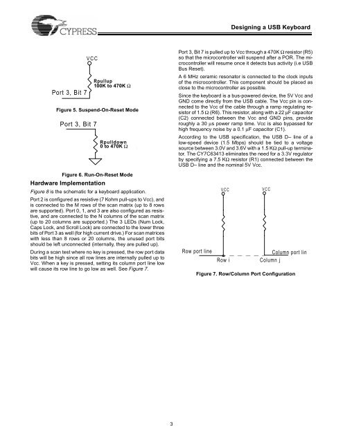
<strong>Designing</strong> a <strong>USB</strong> <strong>Keyboard</strong>Port 3, Bit 7VCCFigure 5. Suspend-On-Reset ModePort 3, Bit 7Figure 6. Run-On-Reset ModeHardware ImplementationRpullup100K100K toto470K470KΩOHMRpulldown0 toto470K470KΩOHMFigure 8 is <strong>the</strong> schematic for a keyboard application.Port 2 is configured as resistive (7 Kohm pull-ups to Vcc), andis connected to <strong>the</strong> M rows of <strong>the</strong> scan matrix (up to 8 rowsare supported). Port 0, 1, and 3 are also configured as resistive,and are connected to <strong>the</strong> N columns of <strong>the</strong> scan matrix(up to 20 columns are supported.) The 3 LEDs (Num Lock,Caps Lock, and Scroll Lock) are connected to <strong>the</strong> lower threebits of Port 3 as well (for high current drive.) For scan matrices<strong>with</strong> less than 8 rows or 20 columns, <strong>the</strong> unused port bitsshould be left unconnected (internally, <strong>the</strong>y are pulled up).During a scan test where no key is pressed, <strong>the</strong> row port databits will be high since all row lines are internally pulled up toVcc. When a key is pressed, setting its column port line lowwill cause its row line to go low as well. See Figure 7.Port 3, Bit 7 is pulled up to Vcc through a 470K Ω resistor (R5)so that <strong>the</strong> microcontroller will suspend after a POR. The microcontrollerwill resume once it detects bus activity (i.e <strong>USB</strong>Bus Reset).A 6 MHz ceramic resonator is connected to <strong>the</strong> clock inputsof <strong>the</strong> microcontroller. This component should be placed asclose to <strong>the</strong> microcontroller as possible.Since <strong>the</strong> keyboard is a bus-powered device, <strong>the</strong> 5V Vcc andGND come directly from <strong>the</strong> <strong>USB</strong> cable. The Vcc pin is connectedto <strong>the</strong> Vcc of <strong>the</strong> cable through a ramp regulating resistorof 1.5 Ω (R6). This resistor, along <strong>with</strong> a 22 µF capacitor(C2) connected between <strong>the</strong> Vcc and GND pins, provideroughly a 30 µs power ramp time. Vcc is also bypassed forhigh frequency noise by a 0.1 µF capacitor (C1).According to <strong>the</strong> <strong>USB</strong> specification, <strong>the</strong> <strong>USB</strong> D– line of alow-speed device (1.5 Mbps) should be tied to a voltagesource between 3.0V and 3.6V <strong>with</strong> a 1.5 KΩ pull-up terminator.The CY7C63413 eliminates <strong>the</strong> need for a 3.3V regulatorby specifying a 7.5 KΩ resistor (R1) connected between <strong>the</strong><strong>USB</strong> D– line and <strong>the</strong> nominal 5V Vcc.Row port lineVCCRow iVCCColumn port linColumn jFigure 7. Row/Column Port Configuration3