Appendix S - SaskPower Electrical Service Requirements
Appendix S - SaskPower Electrical Service Requirements
Appendix S - SaskPower Electrical Service Requirements

You also want an ePaper? Increase the reach of your titles
YUMPU automatically turns print PDFs into web optimized ePapers that Google loves.
FINAL REPORT<strong>Appendix</strong> S - <strong>SaskPower</strong> <strong>Electrical</strong> <strong>Service</strong>S <strong>Requirements</strong>S-1
SECTION 1GENERAL REQUIREMENTSFOR ELECTRIC SERVICE
Section 1General <strong>Requirements</strong> For Electric <strong>Service</strong>101TABLE OF CONTENTS1.1 Definitions............................................................................................................................... 1031.2 Standard Supply .................................................................................................................. 1051.2.1 <strong>SaskPower</strong> Supplied Transformation .......................................................................................... 1051.2.1.1 Single Phase................................................................................................................................. 1051.2.1.2 Polyphase..................................................................................................................................... 1051.2.1.3 Existing Polyphase Supply Voltages........................................................................................... 1051.3 Consumer Leased – <strong>SaskPower</strong> Owned Substations............................................. 1071.3.1 Design.......................................................................................................................................... 1071.3.2 Transformation ............................................................................................................................ 1071.3.3 Location....................................................................................................................................... 1071.3.4 Protection..................................................................................................................................... 1071.3.5 Point of Delivery ......................................................................................................................... 1071.3.6 Stand-by Facilities ....................................................................................................................... 1071.3.7 Revenue Metering........................................................................................................................ 1071.3.8 Costs ............................................................................................................................................ 1071.4 Conditions of <strong>Service</strong>.......................................................................................................... 1091.4.1 Application for <strong>Service</strong>................................................................................................................ 1091.4.2 Construction Charge Quotations ................................................................................................. 1091.4.3 Electric <strong>Service</strong> Agreements........................................................................................................1091.4.4 Permits, Notices and Orders ........................................................................................................1091.4.4.1 <strong>Electrical</strong> Permit .......................................................................................................................... 1091.4.4.2 Contractor Notice of <strong>Electrical</strong> Defects....................................................................................... 1091.4.4.3 Owner Notice of <strong>Electrical</strong> Defects............................................................................................. 1101.4.4.4 <strong>Electrical</strong> <strong>Service</strong> Disconnection Order....................................................................................... 1101.4.5 VA Demand................................................................................................................................. 1101.4.6 Seals and Locks ........................................................................................................................... 1101.4.7 Consumer Instrumentation...........................................................................................................1101.4.8 <strong>Electrical</strong> Protection of Consumer Equipment ............................................................................ 1101.4.9 Access.......................................................................................................................................... 110Electric <strong>Service</strong> <strong>Requirements</strong> November, 2004
102Section 1General <strong>Requirements</strong> For Electric <strong>Service</strong>TABLE OF CONTENTS (Continued)Customer <strong>Service</strong>s Area Map .............................................................................................................. 111<strong>Electrical</strong> Inspections District Map................................................................................................... 112<strong>Electrical</strong> Inspections Division ............................................................................................................ 113Request For <strong>Electrical</strong> <strong>Service</strong> Form................................................................................................ 114Oilfield <strong>Service</strong> Application Form..................................................................................................... 116November, 2004Electric <strong>Service</strong> <strong>Requirements</strong>
Section 1General <strong>Requirements</strong> For Electric <strong>Service</strong>1031.1 DEFINITIONSAerial <strong>Service</strong>Aerial SystemApartment Building /CondominiumBuildingBuried <strong>Service</strong>Buried SystemConsumer's <strong>Service</strong>CodeCommercial Rental Unit (CRU)Different Voltages & <strong>Electrical</strong>Characteristics<strong>Electrical</strong> RoomMain Disconnect/<strong>Service</strong> BoxMetering CabinetMultiple Single Family Dwelling /CondominiumOutside <strong>Service</strong> SplitterPaid <strong>Electrical</strong> PermitPoint of DeliveryRuralSingle Family Detached DwellingSplitterStrip MallSupply <strong>Service</strong>UrbanAerial secondary conductor from the transformer to the point of delivery.<strong>SaskPower</strong>'s Distribution System when high voltage primary conductor(s) areinstalled on poles and extended to pole-mount transformers.Multi-level, multi-family dwelling without a separate direct access at groundlevel.A structure which is detached, or separated, from adjoining structures by firerated walls as per Code.Buried secondary conductors from the transformer to the point of delivery.<strong>SaskPower</strong>'s Distribution System when high voltage primary conductor(s) areburied and normally extended to pad-mount transformers.All that portion of the Consumer's installation from the service box or itsequivalent up to and including the point of delivery.Canadian <strong>Electrical</strong> Code, Part 1, and Saskatchewan Amendments issued by<strong>SaskPower</strong> <strong>Electrical</strong> Inspections Division.Single or multi-level commercial building without a separate external access atground level for each unit.Different phases are considered different characteristics, even if the voltage iscommon. Within the same building, one service must be for dedicated loads(rather than for general distribution).A room or area located within a building or suitably attached to the building withwalk-in access and finished floor, to accommodate the electrical serviceequipment and constructed in accordance with the Code, applicable locallegislation and <strong>SaskPower</strong>.An approved assembly consisting of a metal box or cabinet constructed so that itmay be effectually locked or sealed, containing either service fuses and a serviceswitch or a circuit breaker, and of such design that either the switch or circuitbreaker may be manually operated when the box is closed.An assembly in which instrument transformers are installed, for use in<strong>SaskPower</strong>'s revenue meter.Single family row-housing units, townhouses and duplexes having a separateentrance with direct access at ground level.An enclosure applicable for outdoor use required for connection of utilityconductors to the Consumer's service conductors.A permit is considered valid when the numbered permit and payment is receivedby an authorized <strong>SaskPower</strong> employee (Inspections, Customer <strong>Service</strong>s, or T&DDistrict operating staff).The supply service attachment.Where property is not formally surveyed into lots and blocks. Excludes "RuralCommunities", i.e. hamlets, resorts, etc.A separate building suitable for single family occupancy.An enclosure containing terminal plates or bus bars having main connectors.Commercial building with a separate external access at ground level for eachunit.A set of conductors run by <strong>SaskPower</strong> from its system to a point of delivery.Where property is formally surveyed into lots and blocks. Includes "RuralCommunities”, i.e. hamlets, resorts, etc.Electric <strong>Service</strong> <strong>Requirements</strong> November, 2004
104Section 1General <strong>Requirements</strong> For Electric <strong>Service</strong>(This page intentionally left blank.)November, 2004Electric <strong>Service</strong> <strong>Requirements</strong>
Section 1General <strong>Requirements</strong> For Electric <strong>Service</strong>1051.2 STANDARD SUPPLYAlthough every effort will be made to comply with the Consumer's request, <strong>SaskPower</strong> reserves the right to determinethe supply voltage and load limitations, depending upon the available source and transformation.1.2.1 <strong>SaskPower</strong> Supplied Transformation<strong>SaskPower</strong> will provide and install outdoor transformation for Consumers at the following standard secondary supplyvoltages and at maximum (kVA) capacities indicated. Polyphase service requirements outside the following limitationsfall under Consumer owned substations as per Section 4, or <strong>SaskPower</strong> leased substations as per Section 1.3.There may be limitations to capacities available when supplied from other than <strong>SaskPower</strong>'s 25 kV distribution system.1.2.1.1 Single Phase• 120/240 V 3-wire (167 kVA)• 240/480 V 3-wire (100 kVA)• 120/208 V 3-wire (100 kVA) (Network) (1)• 120 V 2-wire (3 kVA) (2)Notes (1): From a polyphase service.(2): Applicable to metered signs and billboards, and unmetered services only.1.2.1.2 Polyphase• 120/208 V grounded WYE 4-wire (750 kVA) (3)• 277/480 V grounded WYE 4-wire (2500 kVA) (3)• 347/600 V grounded WYE 4-wire (3000 kVA) (3)• 2400/4160 V grounded WYE 4-wire (3000 kVA)Note (3):Consumer is responsible for supplying secondary cable for installations where the main service size isgreater than 800 amps, or where the supply service would exceed 3 conductors per phase.1.2.1.3 Existing Polyphase Supply Voltages• 120/240 V DELTA 4-wire (4)• 480 V DELTA 3-wire (4)Note (4):Increases of capacity for additional load for existing Consumers is allowed (with the same voltage andelectrical characteristics).Electric <strong>Service</strong> <strong>Requirements</strong> November, 2004
106Section 1General <strong>Requirements</strong> For Electric <strong>Service</strong>(This page intentionally left blank.)November, 2004Electric <strong>Service</strong> <strong>Requirements</strong>
Section 1General <strong>Requirements</strong> For Electric <strong>Service</strong>1071.3 CONSUMER LEASED - <strong>SaskPower</strong> OWNED SUBSTATIONS<strong>SaskPower</strong> will provide and maintain, under leasing arrangements, substations with voltages and capacities as per 1.3.2.These substations shall utilize only outdoor transformers.1.3.1 DesignConsumer leased – <strong>SaskPower</strong> owned substations shall be designed by <strong>SaskPower</strong> in conjunction with the Consumer.The substation shall be designed in accordance with the Code, or <strong>SaskPower</strong> standards whichever is most stringent.Upon completion, the substation shall be subject to inspection by the <strong>SaskPower</strong> <strong>Electrical</strong> Inspections Division.1.3.2 TransformationThe substation will normally be designed on the basis of standard transformer sizes and ratings. Non-standard sizes orvoltages may be made available upon special request.Standard three phase oil filled transformer secondary voltages with kVA capacity ranges are as follows:• 2400/4160 V grounded WYE 4-wire (3,001 – 15,000 kVA)• 14400/24940 V grounded WYE 4-wire (3,001 – 75,000 kVA)1.3.3 LocationThe location of a substation shall be determined in co-operation with the Consumer. The substation shall be locatedoutside any building and shall be located on the Consumer's property.1.3.4 ProtectionThe type and characteristics of the substation protection shall be determined by <strong>SaskPower</strong>.1.3.5 Point of DeliveryThe point of delivery and Consumer service attachment shall be the secondary terminals of the substation transformer(s).1.3.6 Stand-by FacilitiesThe requirement for stand-by transformers will be dictated by the Consumer's needs.1.3.7 Revenue MeteringInstrument transformers shall be located on the primary side of the supply transformer. Specific revenue meteringrequirements are covered in Section 4.1.3.8 CostsThe total cost of the substation including design, construction, stand-by transformation and commissioning shall be usedto determine the monthly lease charge.Electric <strong>Service</strong> <strong>Requirements</strong> November, 2004
108Section 1General <strong>Requirements</strong> For Electric <strong>Service</strong>(This page intentionally left blank.)November, 2004Electric <strong>Service</strong> <strong>Requirements</strong>
Section 1General <strong>Requirements</strong> For Electric <strong>Service</strong>1091.4 CONDITIONS OF SERVICE1.4.1 Application for <strong>Service</strong>Application for service shall be made through the applicable <strong>SaskPower</strong> Customer <strong>Service</strong>s office. For contacts andtelephone numbers, please see the Customer <strong>Service</strong>s Area Map, near the end of Section 1. The “Request For <strong>Electrical</strong><strong>Service</strong> Form” shall be completed in full and accompanied by a site plan.1.4.2 Construction Charge QuotationsUpon receipt of the completed “Request For <strong>Electrical</strong> <strong>Service</strong> Form”, complete with site plan, <strong>SaskPower</strong> will, within areasonable period of time, provide the Consumer with a cost quotation and service detail covering the supply ofelectrical service to the Consumer.1.4.3 <strong>Electrical</strong> <strong>Service</strong> AgreementsSpecial circumstances may dictate the desirability of obtaining a signed agreement, at the Consumer's or <strong>SaskPower</strong>'srequest.1.4.4 Permits, Notices and Orders1.4.4.1 <strong>Electrical</strong> PermitAn <strong>Electrical</strong> Permit is issued by the <strong>SaskPower</strong> <strong>Electrical</strong> Inspections Division to the electrical contractors or othersresponsible for the permanent or temporary wiring of, or alterations to, electrical installations. Conversions fromoverhead to underground farm yard distribution are included.An <strong>Electrical</strong> Permit is required for services disconnected for over one year or reconnected after a fire or flood.When a permit is required for a reconnect, and a wooden mast exists, then it shall be replaced with an approved steelservice mast.When a permit is required for a reconnect, as a result of an accident or an act of nature, the service will be permitted tobe repaired to its existing standard.A paid <strong>Electrical</strong> Permit is authorization for <strong>SaskPower</strong> to provide service to the Consumer. The Consumer’s servicemust meet the Code for grounding and clearances.<strong>SaskPower</strong> and the Consumer shall ensure that the service is complete, and that the main switch is left in the openposition on services requiring connection.An <strong>Electrical</strong> Permit is required prior to the connection of a temporary service. A separate or an additional <strong>Electrical</strong>Permit is required when transferring the service from temporary to permanent. A temporary service is valid for a periodof less than two (2) years.Temporary services must be disconnected as soon as practicable after the permanent service is connected.1.4.4.2 Contractor Notice of <strong>Electrical</strong> DefectsA Contractor Notice of <strong>Electrical</strong> Defects is issued by the <strong>SaskPower</strong> <strong>Electrical</strong> Inspections Division to a contractor tomake the installation comply with the Code.Electric <strong>Service</strong> <strong>Requirements</strong> November, 2004
110Section 1General <strong>Requirements</strong> For Electric <strong>Service</strong>1.4.4.3 Owner Notice of <strong>Electrical</strong> DefectsAn Owner Notice of <strong>Electrical</strong> Defects is issued by the <strong>SaskPower</strong> <strong>Electrical</strong> Inspections Division to the owner oroccupant of a premise to make the installation comply with the Code.1.4.4.4 Electric <strong>Service</strong> Disconnection OrderWhen orders to correct defects or hazards are not complied with, the Supervisor <strong>Electrical</strong> Inspector can issue anElectric <strong>Service</strong> Disconnection Order to cut off service on a specific date. <strong>SaskPower</strong> shall disconnect the service inquestion on the date specified unless arrangements have been made with the <strong>SaskPower</strong> <strong>Electrical</strong> Inspections Division.Reconnection of the service shall only be made upon instruction from the <strong>SaskPower</strong> <strong>Electrical</strong> Inspections Division.1.4.5 VA Demand<strong>SaskPower</strong> utilizes VA demand metering on certain rates. Consumers affected by VA demand metering and a poorpower factor are well advised to consider power factor correction for their service.1.4.6 Seals and LocksTo permit access to various equipment by <strong>SaskPower</strong> employees only, seals and locks are placed on the supplyequipment components, where located on the line side of the <strong>SaskPower</strong> meter. Examples of this equipment includesplitters, instrument transformer compartments, meters, metering compartments, conduit fittings, and Consumer's servicebox (without fuses). <strong>Service</strong> boxes containing Consumer fuses will not be sealed so as to provide free access to thefuses. Removal of a seal or lock contravenes the Power Corporation Act. Penalties, enforceable by law, may beimposed as stipulated by the Power Corporation Act.Should it be necessary to break seals to perform electrical wiring alterations, <strong>SaskPower</strong> must either remove the seal, orupon receipt of advance notification, authorize the seal(s) removal. <strong>SaskPower</strong> shall be notified by the contractor whenthe work is completed to reseal the service. Upon completion of the work <strong>SaskPower</strong> will reseal the installation.1.4.7 Consumer InstrumentationConsumer's relays, instruments or other devices shall not be connected in <strong>SaskPower</strong> revenue metering circuits and shallnot be mounted on or in any meter enclosures, instrument transformer enclosures or any other equipment supplied foruse by <strong>SaskPower</strong>.1.4.8 <strong>Electrical</strong> Protection of Consumer Equipment<strong>SaskPower</strong> shall not assume responsibility for the electrical protection of Consumer-owned equipment, including thatfor single phasing protection. <strong>Electrical</strong> protection shall be installed as per the Code.1.4.9 AccessFor all installations of <strong>SaskPower</strong> equipment (such as metering equipment or service cable terminations), <strong>SaskPower</strong>staff shall have access to all such equipment for the purpose of changing, servicing, testing and reading. Where accessto the equipment is unobtainable due to locked doors, the local <strong>SaskPower</strong> office shall be provided with a key. Whenmutually agreeable, <strong>SaskPower</strong> will supply a lock box for storage of the key.November, 2004Electric <strong>Service</strong> <strong>Requirements</strong>
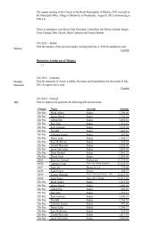
Section 1General <strong>Requirements</strong> For Electric <strong>Service</strong>111CUSTOMER SERVICES BUSINESS MANAGERS1 - MOOSE JAW / SWIFT CURRENT AREA - 306 778-75282 - REGINA AREA - 306 566-24013 - WEYBURN AREA - 306 848-7231(INCLUDES GRENFELL, KIPLING & MOOSOMINOILFIELD CUSTOMERS)4 - YORKTON AREA - 306 786-12155 - SASKATOON AREA - 306 934-78326 - NORTH BATTLEFORD AREA - 306 445-18507 - PRINCE ALBERT AREA - 306 953-7602NO CHARGE 1-888-SKPOWER (757-6937)MEADOW LAKELLOYDMINSTERTURTLEFORDSPIRITWOODSHELLBROOKMEATHPARK7PRINCEALBERTNIPAWINCARROTRIVERMAIDSTONE6NORTHBATTLEFORDMELFORTTISDALEHUDSON BAYUNITYROSTHERNWAKAWKERROBERTBIGGARSASKATOON5COLONSAYHUMBOLDTWATSONWADENASTURGISKINDERSLEYROSETOWNWATROUSWYNYARDCANORAKAMSACKMAPLECREEKESTONLEADERGULLLAKEELROSE1SWIFTCURRENTOUTLOOKCENTRALBUTTEDAVIDSONMOOSE JAWPUNNICHYSTRASBOURGFORTQU'APPELLELUMSDENREGINACITY2REGINARURALYORKTON4MELVILLEESTERHAZYGRENFELLMOOSOMINKIPLINGSHAUNAVONGRAVELBOURGASSINIBOIA3WEYBURNSTOUGHTONCARLYLERADVILLEESTEVANOXBOWCUSTOMER SERVICES AREA OFFICESCUSTOMER SERVICES SALES BOUNDARIESTD\LIBRARY\CUSTSERV\CUSTOMER_SERVICES_SALES.DWGJanuary 15/2003 (MM)CUSTOMER SERVICES SALESElectric <strong>Service</strong> <strong>Requirements</strong> November, 2004
112Section 1General <strong>Requirements</strong> For Electric <strong>Service</strong>9A14139B11125 106781B1A23174November, 2004Electric <strong>Service</strong> <strong>Requirements</strong>
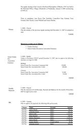
Section 1General <strong>Requirements</strong> For Electric <strong>Service</strong>113<strong>SaskPower</strong> <strong>Electrical</strong> Inspections DivisionH. Grant Schellhorn, Chief <strong>Electrical</strong> Inspector, Regina 566-2515, Cellular 533-4871John D. Nightingale, - Supervisor <strong>Electrical</strong> Inspector, Regina 566-2516, Cellular 536-6551Karstein E. Thompson, - Supervisor <strong>Electrical</strong> Inspector, Saskatoon 934-7720, Cellular 221-0917Lyle P. Radom, - Supervisor Business & Technical <strong>Service</strong>s, Regina 566-2518, Cellular 539-1321David Dell, - <strong>Electrical</strong> Plans Review, Regina 566-2541Regina Office AddressSaskatoon Office AddressBuilding # 1 2230 6 th AvenueRegina, SK, S4P 0S1Inquiry 566-2500 Fax 566-2906PO Box 1560, 1370 Fletcher RoadSaskatoon, SK, S7K 3R3Inquiry 934-7737 Fax 934-7736District # <strong>Electrical</strong> Inspector Office location & Area Address1A Don King778-7512 Cell 741-28071B Mel Podhorodecki778-7519 Cell 741-03432 Brent Woods694-8257 Cell 631-17313 Doug Naldrett566-2531 Cell 536-65504 John Burak637-4235 Cell 421-37035 Kevin Wanner463-5212 Cell 463-71966 Clark Ward934-7725 Cell 222-48197 Lorie Graff566-2530 Cell 536-65498 Guy Brideau786-1229 Cell 621-15929A Wes Saworski445-1862 Cell 441-05119B Cliff Kenney445-1861 Cell 441-321910 Derm Zimmerman934-7739 Cell 221-091811 Don Craig934-7721 Cell 221-296012 Glen Jestin878-1515 Cell 873-739913 Rod Pack953-7666 Cell 961-747014 David Pilon953-7678 Cell 961-263415A Wayne Davies566-2529 Cell 536-412115B Darrell Leontowicz566-2528 Cell 536-412215C Les Beros566-2532 Cell 536-466516A Trevor Bourassa934-7723 Cell 221-091316B Eric Solvason934-7722 Cell 222-779416C Grant Stone934-7724 Cell 221-091617 Dean Schill786-1243 Cell 621-1102Swift Current City and Rural 1800 Aberdeen St., Box 580Swift Current S9H 3W4Swift Current City and Rural 1800 Aberdeen St., Box 580Swift Current S9H 3W4Moose Jaw City and Rural 880 Lillooet St. West, Box 1240Moose Jaw S6H 4P9Regina Rural Bldg. # 1, 2230 6 th Ave.Regina S4P 0S1Estevan City and Rural 234 5 th St.Estevan S4A 0X2Kindersley Rural Highway # 7 East, Box 1119Kindersley S0L 1S0Saskatoon City and Rural PO Box 1560, 1370 Fletcher RoadSaskatoon S7K 3R3Regina Rural Bldg. # 1, 2230 6 th Ave.Regina S4P 0S1Yorkton City and Rural 300 Broadway St. WestYorkton S3N 0M1North Battleford City and Rural 9905 Thatcher Ave., Box 760North Battleford S9A 2Z2North Battleford Battleford and 9905 Thatcher Ave., Box 760RuralNorth Battleford S9A 2Z2Saskatoon Rural PO Box 1560, 1370 Fletcher RoadSaskatoon S7K 3R3Saskatoon Rural PO Box 1560, 1370 Fletcher RoadSaskatoon S7K 3R3Tisdale Rural 1106 - 101 st Ave., Box 1900Tisdale S0E 1T0Prince Albert City and Rural 1330 Central Ave. E., Box 5900Prince Albert S6V 7V6Prince Albert City and Rural 1330 Central Ave. E., Box 5900Prince Albert S6V 7V6Regina City Bldg. # 1, 2230 6 th Ave.Regina S4P 0S1Regina City Bldg. # 1, 2230 6 th Ave.Regina S4P 0S1Regina City Bldg. # 1, 2230 6 th Ave.Regina S4P 0S1Saskatoon City PO Box 1560, 1370 Fletcher RoadSaskatoon S7K 3R3Saskatoon City PO Box 1560, 1370 Fletcher RoadSaskatoon S7K 3R3Saskatoon City PO Box 1560, 1370 Fletcher RoadSaskatoon S7K 3R3Yorkton Rural 300 Broadway St. WestYorkton S3N 0M1Electric <strong>Service</strong> <strong>Requirements</strong> November, 2004
114Section 1General <strong>Requirements</strong> For Electric <strong>Service</strong>1-888-SKPOWER (757-6937)Notification # (Unique ID tracking #, supplied by <strong>SaskPower</strong>)Request for <strong>Electrical</strong> <strong>Service</strong> – Page 1 of 2Consumer InformationConsumer Name:Spouse/Roommate:Mailing Address:Town:Postal Code:Home Phone #: Fax #: Cell Phone #:Email:Employment Information:Consumer:Spouse / Roommate:Phone Number:Phone Number:Consumer I.D.:I.D. #1:I.D. #2:<strong>SaskPower</strong> requires two pieces of identification, one of which should be a driver’s license.Type:Type:Emergency Contact Name:Phone #:<strong>Service</strong> Location:<strong>Service</strong> Town:Site Plan Attached: Yes No (Indicating point of delivery)Contact from <strong>SaskPower</strong> can be expected regarding point of delivery.Date of Request:Date <strong>Service</strong> Required:SEE PAGE 2 FOR SERVICE REQUIREMENTSNovember, 2004Electric <strong>Service</strong> <strong>Requirements</strong>
Section 1General <strong>Requirements</strong> For Electric <strong>Service</strong>115Request for <strong>Electrical</strong> <strong>Service</strong> – Page 2 of 21-888-SKPOWER (757-6937)Notification # (Unique ID tracking #, supplied by <strong>SaskPower</strong>)<strong>Service</strong> <strong>Requirements</strong>Type Of <strong>Service</strong>: (Please Mark X in the Space )Residential Farm General <strong>Service</strong>Consumer Main Size: (Please Mark X in the Space)100 A 200 A 400 A Other ___________ ASupply Voltage: (Please Mark X in the Space Below)Single Phase:Three Phase:120/240 V 3 wire 120/208 V 4 wire240/480 V 3 wire 277/480 V 4 wire347/600 V 4 wireOtherMotor Loads: (Please attach a complete list of motor loads)Largest motor to be started: 3 Phase kW, or HP1 Phase KW, or HPHeating Load: kW Lighting Load: kWOther Load:Hours of Operation:Consumer Signature:Date:Meter InstallationA separate application for meter installation must be made to 1-888-SKPOWER (757-6937) when the Consumer’s wiring is complete and service isrequired.Conditions of <strong>Service</strong> ChecklistAll necessary easements, land rights, and approvals can be obtained.Consumer to supply a meter socket, as per the “Electric <strong>Service</strong> <strong>Requirements</strong>”, to be located: indoors outdoorsConsumer to supply an outdoor splitter box sized as per the “Electric <strong>Service</strong> <strong>Requirements</strong>” to accommodate ________conductors.Consumer to install <strong>SaskPower</strong> supplied instrument transformers as per the “Electric <strong>Service</strong> <strong>Requirements</strong>”. Consumer supplied cabinet willbe readily accessible for maintenance with a means of sealing by <strong>SaskPower</strong>.All cable routes must be free of obstructions and final grade is to be indicated before construction commences.This service will be put into account billing and will be subject to minimum bills when the meter is installed or sixty (60) days after service hasbeen made available, whichever is sooner.Consumer to advise <strong>SaskPower</strong> of any abnormal site conditions, including those that may preclude a buried service.Other Conditions:Rebate DetailsShould this electrical extension be utilized by another Consumer within a period of five (5) years from the time of installation, the Consumer shall beentitled to a construction charge rebate based on shared line costs.ApplicableNon-applicableElectric <strong>Service</strong> <strong>Requirements</strong> November, 2004
116Section 1General <strong>Requirements</strong> For Electric <strong>Service</strong>1-888-SKPOWER (757-6937)Notification # (Unique tracking #, supplied by <strong>SaskPower</strong>)Oilfield <strong>Service</strong> ApplicationContact Person: (Construction Information)Contact Person:Telephone Number: Fax Number: Email:Consumer Information: (Invoicing and Energy Billing)Company Name:Contact Person:Telephone Number: Fax Number: Email:New <strong>Service</strong> Location: (Surface Location)LSD _____ of _____ - _____ - _____ W _____ M ______ HP _____ HP Date ________________LSD _____ of _____ - _____ - _____ W _____ M ______ HP _____ HP Date ________________Capacity Increase: (Existing Location)Existing HP + Added HP = Total HPLSD _____ of _____ - _____ - _____ W _____ M ___________ ___________ ____________Land Rights / Issues:Does the Lease Agreement with landowner provide for <strong>SaskPower</strong> facilities? Yes [ overhead underground ] NoIs a work permit required prior to going on site? Yes NoLoad Data:Plot Plans/Site Plans to scale (Digital AutoCad preferred)MUST be provided for this application to be processed.<strong>Service</strong> Voltage: Volts Phase Wires<strong>Service</strong> Entrance / MCC:Load Description:AmpsPumpjack Screwpump Water Injection Battery SiteDate Required for Electric <strong>Service</strong>:Current Status:Site Prepared Drilling in Progress Drilling Completed Pumpjack InstalledConsumer Signature:Date:November, 2004Electric <strong>Service</strong> <strong>Requirements</strong>
SECTION 2TECHNICALREQUIREMENTSFOR SERVICE UP TO ANDINCLUDING 5 kV
Section 2Technical <strong>Requirements</strong> For <strong>Service</strong> Up to and Including 5 kV201TABLE OF CONTENTS2.1 RESIDENTIAL...................................................................................................................................2072.1.1 Applicability...............................................................................................................................................2072.1.2 General <strong>Requirements</strong>................................................................................................................................2072.1.3 Point of Delivery........................................................................................................................................2082.1.4 Buried <strong>Service</strong> <strong>Requirements</strong>.....................................................................................................................2082.1.5 Aerial <strong>Service</strong> <strong>Requirements</strong>......................................................................................................................2102.1.6 Metering.....................................................................................................................................................2102.2 FARM .....................................................................................................................................................2212.2.1 Applicability...............................................................................................................................................2212.2.2 General <strong>Requirements</strong>................................................................................................................................2212.2.3 Point of Delivery........................................................................................................................................2222.2.4 Buried <strong>Service</strong> <strong>Requirements</strong>.....................................................................................................................2222.2.5 Metering.....................................................................................................................................................2252.3 GENERAL SERVICE......................................................................................................................2332.3.1 Applicability...............................................................................................................................................2332.3.2 General <strong>Requirements</strong>................................................................................................................................2332.3.3 Point of Delivery........................................................................................................................................2342.3.4 Buried <strong>Service</strong> <strong>Requirements</strong>.....................................................................................................................2352.3.5 Aerial <strong>Service</strong> <strong>Requirements</strong>......................................................................................................................2392.3.6 Metering.....................................................................................................................................................2402.4 OILFIELD ............................................................................................................................................2512.4.1 Applicability...............................................................................................................................................2512.4.2 General <strong>Requirements</strong>................................................................................................................................2512.4.3 Point of Delivery........................................................................................................................................2522.4.4 Buried <strong>Service</strong> <strong>Requirements</strong>.....................................................................................................................2522.4.5 Metering.....................................................................................................................................................253FIGURES & TABLES...........................................................................................................................................259Electric <strong>Service</strong> <strong>Requirements</strong> November, 2004
202Section 2Technical <strong>Requirements</strong> For <strong>Service</strong> Up to and Including 5 kV(This page intentionally left blank.)November, 2004Electric <strong>Service</strong> <strong>Requirements</strong>
Section 2.1Technical <strong>Requirements</strong> For <strong>Service</strong> Up to and Including 5 kVRESIDENTIAL203Section 2.1RESIDENTIALElectric <strong>Service</strong> <strong>Requirements</strong> November, 2004
204Section 2.1Technical <strong>Requirements</strong> For <strong>Service</strong> Up to and Including 5 kVRESIDENTIAL(This page intentionally left blank.)November, 2004Electric <strong>Service</strong> <strong>Requirements</strong>
Section 2.1Technical <strong>Requirements</strong> For <strong>Service</strong> Up to and Including 5 kVRESIDENTIAL205TABLE OF CONTENTS2.1 RESIDENTIAL...................................................................................................................................2072.1.1 Applicability...............................................................................................................................................2072.1.2 General <strong>Requirements</strong>................................................................................................................................2072.1.2.1 <strong>Service</strong> and Metering Exceptions...............................................................................................................2072.1.3 Point of Delivery........................................................................................................................................2082.1.4 Buried <strong>Service</strong> <strong>Requirements</strong>.....................................................................................................................2082.1.4.1 Single Family Detached Dwelling .............................................................................................................2092.1.4.1.1 Urban..........................................................................................................................................................2092.1.4.1.2 Rural...........................................................................................................................................................2092.1.4.1.3 Mobile Home (Park) ..................................................................................................................................2092.1.4.2 Multiple Single Family Dwelling / Condominium.....................................................................................2092.1.4.3 Apartment Buildings / Condominiums ......................................................................................................2102.1.5 Aerial <strong>Service</strong> <strong>Requirements</strong>......................................................................................................................2102.1.6 Metering.....................................................................................................................................................2102.1.6.1 General.......................................................................................................................................................2102.1.6.2 Meter Mounting Devices............................................................................................................................2112.1.6.2.1 General.......................................................................................................................................................2112.1.6.2.2 Self-Contained Meter Sockets....................................................................................................................2112.1.6.2.3 400 A, 120/240 V Self-Contained Meter Sockets......................................................................................2122.1.6.2.4 Transformer-Rated Meter Sockets .............................................................................................................2122.1.6.2.5 Specifications.............................................................................................................................................2122.1.6.3 <strong>Electrical</strong> Room..........................................................................................................................................2132.1.6.4 Instrument Transformers and Enclosures...................................................................................................2132.1.6.4.1 General.......................................................................................................................................................2132.1.6.4.2 Instrument Transformers............................................................................................................................2142.1.6.4.3 Instrument Transformer Enclosures...........................................................................................................2142.1.6.4.4 Conduit and Secondary Wiring <strong>Requirements</strong>...........................................................................................215Figures and Tables...........................................................................................................................................................259Electric <strong>Service</strong> <strong>Requirements</strong> November, 2004
206Section 2.1Technical <strong>Requirements</strong> For <strong>Service</strong> Up to and Including 5 kVRESIDENTIAL(This page intentionally left blank.)November, 2004Electric <strong>Service</strong> <strong>Requirements</strong>
Section 2.1Technical <strong>Requirements</strong> For <strong>Service</strong> Up to and Including 5 kVRESIDENTIAL2072.1 RESIDENTIAL2.1.1 ApplicabilityThese requirements apply to the extension of service to any dwelling unit used primarily for domestic purposes on apermanent or seasonal basis, not including commercially operated self-contained rental units in resort areas.2.1.2 General <strong>Requirements</strong>When an aerial or buried system exists, <strong>SaskPower</strong> will normally install a buried supply service to all new consumers.However, circumstances may dictate that an aerial service remains or be installed. At the time of application for service,the Consumer shall advise <strong>SaskPower</strong> of any abnormal site conditions, including those that may preclude a buriedservice.Clearances from the transformer to buildings shall conform to the Code, and are shown in Table 2-3. When theseclearances cannot be met, the Consumer shall supply and install barriers between the transformer and the building as perFigures 2-21 and 2-22.Separations of <strong>SaskPower</strong>'s direct buried power conductors to various facilities shall be as per Table 2-3. Clearances foraerial services shall be as per Figure 2-20. Overhead clearances, as applicable, shall be as per Table 2-5.2.1.2.1 <strong>Service</strong> and Metering ExceptionsA single meter shall measure energy consumed by a single Consumer in any individual premise (including apartmentsuites). Exceptions are:• senior citizens apartment complexes may be bulk or individually metered at the option of the owner.• when individual circumstances warrant, an additional service(s) or meter(s) may be provided for cases, asallowed by the Code, such as:• different voltage and electrical characteristics.• separate buildings (detached or separated by fire rated wall as per Code).• fire pumps.• multiple single family dwelling / condominium.• when individual circumstances warrant, an additional meter(s) per service may be provided for cases such asdifferent rate classifications (e.g., 120/240 V kWh meter (1) on commercial rate).Note (1):Meter is for common facilities.Electric <strong>Service</strong> <strong>Requirements</strong> November, 2004
208Section 2.1Technical <strong>Requirements</strong> For <strong>Service</strong> Up to and Including 5 kVRESIDENTIAL2.1.3 Point of DeliveryOptions for point of delivery are listed below. See 2.1.4 or 2.1.5 for specific service termination requirements todetermine the applicable option for point of delivery. The ownership of facilities to the point of delivery shall remainwith <strong>SaskPower</strong>.• single point:• Consumer supplied 200 A, self-contained meter socket.• Consumer supplied 400 A, 120/240 V, self-contained meter socket. (2)• Consumer supplied splitter (attached to building, or free-standing).• Consumer supplied multi-position meter trough, with blank compartment.• Consumer supplied switchgear (primary voltages up to 5 kV).• Consumer supplied single phase service termination / CT enclosure (maximum 300 V & 800 A) (3)• Consumer supplied polyphase service termination / CT enclosure (maximum 300 V & 600 A) (3)• <strong>SaskPower</strong> supplied Rural Metering (rural services only).• secondary terminals of <strong>SaskPower</strong> supplied pad-mounted transformer (4) .Note (2):Note (3):Note (4):A fused disconnect is required immediately after the meter socket (rural only).A fused disconnect is required immediately after the CT enclosure.Whether the metering is at <strong>SaskPower</strong>'s pad-mounted transformer or at the Consumer'sequipment, the Consumer shall, in consultation with <strong>SaskPower</strong>, supply, install and terminatethe secondary conductors. Connection to or disconnection from <strong>SaskPower</strong>'s system shallonly be made by individuals authorized by <strong>SaskPower</strong>. Suitable cable support (as per Code)shall be supplied and installed by the Consumer in a manner approved by <strong>SaskPower</strong>.• multiple point:• individual Consumer supplied meter sockets on multi-family dwelling.• multiple Consumer supplied splitters on multi-family dwelling.• Consumer supplied multi-position meter trough.• fire pump (when a separate service is requested), the options are:• Consumer supplied splitter (5) .• additional point of delivery.Note (5):The Consumer supplied conductors to the fire pump shall be connected to the Consumer'sside of the splitter block.For apartment buildings, the location of the supply transformer and point of delivery will be by mutual agreement afterload, voltage drop, splitter, and maintenance accessibility requirements have been considered.The location for support attachments for a buried or an aerial supply service shall normally be located within one metreof the point on the building nearest to <strong>SaskPower</strong>'s supply facilities. However, an alternate Consumer preferred locationshall be permitted providing such location imposes no technical or physical impediment to <strong>SaskPower</strong>.2.1.4 Buried <strong>Service</strong> <strong>Requirements</strong>The Consumer is responsible for supplying the secondary cable for installations where the main service size is greaterthan 800 amps, or where the supply service would exceed 3 conductors per phase.November, 2004Electric <strong>Service</strong> <strong>Requirements</strong>
Section 2.1Technical <strong>Requirements</strong> For <strong>Service</strong> Up to and Including 5 kVRESIDENTIAL2092.1.4.1 Single Family Detached DwellingWhen the main service box is 200 A or less, and when the supply service conductors do not exceed 4/0 in size, themeans of attachment shall consist of a 200 A meter socket. <strong>SaskPower</strong> shall terminate its supply service to the lineterminals of the meter socket.When the supply service conductors exceed 4/0 in size, or when the main service box exceeds 200 A, options are:• Consumer supplied 400 A, 120/240 V, self-contained meter socket as per Figure 2-4 and Table 2-1.• Consumer supplied outside service splitter as per Figure 2-7 and 2-8 and Table 2-1.• Consumer supplied service termination / CT enclosure as per Figure 2-4 (a) or 2-4 (b) and Table 2-1.2.1.4.1.1 Urban<strong>Service</strong> option is a:• Consumer supplied 200 A self-contained meter socket as per Figure 2-1.2.1.4.1.2 Rural<strong>Service</strong> options are:• Consumer supplied 200 A self-contained meter socket as per Figure 2-1.• <strong>SaskPower</strong> supplied Rural Metering as per Figure 2-12, 2-13 or 2-14.2.1.4.1.3 Mobile Home (Park)<strong>Service</strong> options are:• Consumer supplied 200 A self-contained meter socket as per Figure 2-1.• <strong>SaskPower</strong> supplied Mobile Trailer (Park) Meter Installation, as per Figure 2-3.2.1.4.2 Multiple Single Family Dwelling / CondominiumMultiple single family dwellings / condominiums include all single family row-housing units, townhouses and duplexeshaving a separate entrance with direct access at ground level, as shown in Figure 2-11. Options for service include oneor more of the following:• individual Consumer meter socket on each single-family unit (duplex), as per Figure 2-1 (6) .• Consumer supplied multi-position meter trough, with blank compartment, as per Figure 2-5 (6) .• Consumer supplied splitter with horizontal multi-meter trough(s) as per Figure 2-6 (6) .• secondary terminals of <strong>SaskPower</strong> supplied pad-mounted transformer.Note (6):Maximum of two (2) points of delivery per building.When a splitter is used, its rating shall not exceed 800 A. However, the total of the ratings of the individual metersockets may exceed 800 A, as allowed by Code.Electric <strong>Service</strong> <strong>Requirements</strong> November, 2004
210Section 2.1Technical <strong>Requirements</strong> For <strong>Service</strong> Up to and Including 5 kVRESIDENTIAL2.1.4.3 Apartment Buildings / CondominiumsApartment buildings / condominiums include multi-level, multi-family dwelling without a separate direct access atground level, as shown in Figure 2-11. Options for service include:• <strong>SaskPower</strong> Supplied <strong>Service</strong>:• Consumer supplied splitter, sizes as per Table 2-1 and Figure 2-7 and 2-8 or 2-9.• Consumer supplied switchgear (7) .• Consumer supplied service termination / CT enclosure as per Figure 2-4 (a) or 2-4 (b) and Table 2-1.Note (7):The Consumer shall ensure that when <strong>SaskPower</strong> extends high voltage supply cables to theConsumer's cable termination compartment in the switchgear, the compartment shall haveadequate phase barriers and grounding means.• Consumer Supplied <strong>Service</strong>:• electrical room, as per 2.1.6.3.• secondary terminals of <strong>SaskPower</strong> supplied pad-mounted transformer.2.1.5 Aerial <strong>Service</strong> <strong>Requirements</strong> (limited to specific conditions)Aerial supply services shall be limited to 200 A, and may apply to any type of residential dwelling.The Consumer shall provide the means of attachment for the <strong>SaskPower</strong> service drop. It shall consist of an approvedsteel service mast kit, or a single 12 mm eyebolt secured to the wall. The eyebolt shall not be bolted to the roof or eaves.The use of lag screws, lag screw insulators, or wall-mounted racks are not acceptable. The Consumer's service headlocation shall be as per Code and Figure 2-20. Clearances for aerial supply service shall be as per Code and Figure 2-20.When a permit is required for a reconnect, and a wooden mast exists, then it shall be replaced with an approved steelservice mast.2.1.6 Metering2.1.6.1 GeneralWhen the supply service is from a 4-wire wye system, the metering facilities shall be 4-wire wye requiring the systemneutral to be brought into the instrument transformer compartment complete with connecting lug for connection to thevoltage transformer.When multiple meters are used, and are indoors, they shall be grouped together in an electrical room.For metering of multi-use projects, <strong>SaskPower</strong> may, for economic and practical reasons, determine the supply voltage tobe at a higher voltage level than is required by some or all of the end users. To meter each tenant separately, <strong>SaskPower</strong>will permit metering at both the supply voltage and at any other common voltage for which the owner provides thenecessary transformation.November, 2004Electric <strong>Service</strong> <strong>Requirements</strong>
Section 2.1Technical <strong>Requirements</strong> For <strong>Service</strong> Up to and Including 5 kVRESIDENTIAL2112.1.6.2 Meter Mounting Devices2.1.6.2.1 GeneralThe meter socket will normally be supplied and installed by the Consumer, with the following exceptions:• Rural Metering Unit for services up to and including 200 A.• when the metering is at the secondary terminals of <strong>SaskPower</strong>’s 3-phase pad-mounted transformer (optional forsenior citizen’s complexes). This applies to cases where:• the transformer is dedicated to one Consumer, and• Consumer supplies the secondary conductors, and• the supply voltage is less than 750 Volts.The use of current bypass switches is not permitted when self-contained meter sockets are used. However, for servicesgreater than 200 A that do not utilize the 400 A self-contained meter socket and current transformer (as shown in Figure2-4) a current bypass switch shall be used and installed as per Figure 2-8.All meter sockets shall:• be supplied complete with screw type or snap action sealing rings. Slip lock sealing rings and ringless metersockets are not permitted.When the point of delivery is the secondary terminals of <strong>SaskPower</strong>’s pad-mounted transformer, the metering optionsare:• Consumer supplied meter socket(s) at their distribution centre.• <strong>SaskPower</strong> supplied meter socket at the 3-phase pad-mounted transformer, as per Figure 2-17.2.1.6.2.2 Self-Contained Meter SocketsMeter sockets shall be configured and wired as per Figures 2-23 and 2-24, and shall be installed for:• single family detached dwelling:• on the line side of the individual Consumer’s service/main disconnect when the service voltage doesnot exceed 300 V between conductors.• multiple single family dwelling / condominium:• on the line side of the individual Consumer’s service/main disconnect when the service voltage doesnot exceed 300 V between conductors.• apartment buildings / condominiums:• on the load side of the individual Consumer's service/main disconnect, grouped together in anapproved electrical room, as per Figure 2-9.Electric <strong>Service</strong> <strong>Requirements</strong> November, 2004
212Section 2.1Technical <strong>Requirements</strong> For <strong>Service</strong> Up to and Including 5 kVRESIDENTIAL2.1.6.2.3 400 A, 120/240 V Self-Contained Meter SocketsMeter sockets shall be configured and wired as per Figures 2-23 (5) and 2-25 (1), and installed as per Figure 2-4.When a 400 A, 120/240 V self-contained meter socket is used, the entire unit shall be located outdoors. It shall not beused on 120/208 V 4-wire <strong>SaskPower</strong> distribution due to the meter socket configuration.2.1.6.2.4 Transformer-Rated Meter SocketsMeter sockets shall be:• configured and wired as per Figure 2-23 (5), (6) & (7), and Figure 2-25, and installed as per Figure 2-8.• complete with a ground connection.• within a circuit length of 11 metres from the indoor instrument transformer enclosure. Exceptions require priorapproval from <strong>SaskPower</strong>, Metering <strong>Service</strong>s.• located outdoors. Exceptions include:• when meters are grouped together in an electrical room(s).• when meters are located in the same switchgear assembly as the instrument transformers and in aseparate compartment. The meter compartment shall conform to the following dimensions:• Depth - 380 mm (15") minimum to 450 mm (18") maximum• Height - 850 mm (34") minimum• Width - 600 mm (24") minimumThe meter compartment shall be equipped with a hinged door, flush with the front of the switchgear,with provisions for sealing by <strong>SaskPower</strong>. A window is to be provided if the Consumer wishes to readthe meter. The meter compartment is to be located so that the meter can be mounted with its centreline at a height of 1500 mm to 1800 mm above floor level.• when the meter socket is separate from the switchgear, it may be wall-mounted adjacent to theswitchgear, with approval from <strong>SaskPower</strong>, Metering <strong>Service</strong>s.2.1.6.2.5 SpecificationsSingle Phase Buried <strong>Service</strong>:• 200 A Meter socketsThe meter socket assembly shall:• have 1/2" stud-type line side and neutral terminals so arranged as to permit straight in conductorconnections and suitable for securing <strong>SaskPower</strong> compression lugs rated for #6 to 4/0.• have minimum dimensions of 455 x 300 x 125 mm (18 x 12 x 5 inches).A single meter socket, rated up to 200 A, with dual wire connectors on the load side, shall be permitted twosubdivisions. However, the subdivision of the consumer service can be accomplished within the dual lug metersocket provided that the total ampere rating of the two consumer service disconnects does not exceed theampere rating of the meter socket.For service conductors exceeding 4/0, a splitter shall be used in conjunction with the meter socket. Thesplitter becomes <strong>SaskPower</strong>’s point of delivery.November, 2004Electric <strong>Service</strong> <strong>Requirements</strong>
Section 2.1Technical <strong>Requirements</strong> For <strong>Service</strong> Up to and Including 5 kVRESIDENTIAL213• 400 A, 120/240 V Self-Contained Meter Socket (Figure 2-4)The enclosure shall:• have stud type line and neutral terminals so arranged as to permit straight in conductor connectionsand suitable for securing <strong>SaskPower</strong> compression lugs.• have minimum dimensions of 914 x 508 x 203 mm (36 x 20 x 8 inches).• be capable of using 78 mm (3 inch) conduit.The Consumer shall install the <strong>SaskPower</strong> supplied 3-wire current transformer. <strong>SaskPower</strong> shall make allterminations to the secondary of the current transformer.A single meter socket, rated up to 400 A, with dual wire connectors on the load side shall be permitted twosubdivisions. However, the subdivision of the consumer service can be accomplished within the dual lug metersocket provided that the total ampere rating of the two consumer service disconnects does not exceed theampere rating of the meter socket.For supply service conductors exceeding 500 kcmil, or multiple conductors per phase, a splitter shall be used inconjunction with the meter socket. The splitter becomes <strong>SaskPower</strong>’s point of delivery.2.1.6.3 <strong>Electrical</strong> RoomThe electrical room shall conform to all aspects of the Code, and shall:• be located within a building or suitably attached to the building with walk-in access and finished floor.• be accessible directly from the exterior of the building or from a common hallway.• be accessible via stairs, if not at ground level. Access via a ladder is not acceptable.• be suitable to permit future modifications.• maintain a minimum clearance of 1000 mm in front of all electrical equipment.• maintain a minimum clear space of 600 mm when a hinged door or panel of an instrument enclosure is in anopen position that would block an exit route.• have one duplex electrical receptacle installed in close proximity to the electrical equipment.2.1.6.4 Instrument Transformers & Enclosures2.1.6.4.1 GeneralWhen the main service exceeds 200 A or 600 V, and the metering is not at <strong>SaskPower</strong>’s facilities, the instrumenttransformer enclosure shall be supplied and installed by the Consumer. For service voltage at 4160 V, the Consumershall supply and install the instrument transformer enclosure and meter socket.Revenue metering instrument transformers and other associated equipment supplied by <strong>SaskPower</strong> shall be usedexclusively for the purpose of <strong>SaskPower</strong> revenue metering.For services with multiple instrument transformer enclosures, each enclosure shall have a separate means of disconnect.Electric <strong>Service</strong> <strong>Requirements</strong> November, 2004
214Section 2.1Technical <strong>Requirements</strong> For <strong>Service</strong> Up to and Including 5 kVRESIDENTIAL2.1.6.4.2 Instrument TransformersWhen the Consumer supplies the instrument transformer enclosure, the instrument transformers shall be installed:• and connected by the Consumer as per Figure 2-25.• to permit the complete removal or installation.• using all manufacturer’s mounting holes.• such that the name plates are clearly visible.Instrument transformers will not be shipped out of the province for installing in switchgear. Instrument transformerdimension diagrams will be forwarded upon request.Voltage transformers, 700 V class, shall be without fuses and be stationary mounted. Voltage transformers, 5 kV class,may be equipped with one fuse per transformer centrally mounted for 3-phase, 4-wire wye circuits as per Figure 2-26.Current transformers, 5 kV class, shall be as per Figure 2-26. The compartment may be required to be equipped with adraw out type or swing out type carriage with disconnect provisions for de-energizing and grounding the primary ofeach transformer upon withdrawal.2.1.6.4.3 Instrument Transformer EnclosuresWhen the Consumer supplies the instrument transformer enclosure, it shall:• be equipped with a hinged door with provision for padlocking and sealing by <strong>SaskPower</strong>.• contain mounting plates or other acceptable means for securing the transformers.• have an insulated splitter block provided for neutral conductors.• be of the dimensions as per Table 2-2 (for services not utilizing bar type buss structure).For service entrance panels utilizing bar type buss structure and manufactured switchgear, provision shall be made formounting current transformers and voltage transformers in a separate and completely barriered compartment. Thecompartment shall be large enough to contain three current transformers and three voltage transformers and to be readilyaccessible for maintenance and replacement of transformers with a means for padlocking and sealing by <strong>SaskPower</strong>.The instrument transformer enclosure shall be a minimum of 300 mm (12") above the floor.In addition to the electrical clearances specified in the applicable CSA standard, a minimum physical separation of 50mm must be maintained between instrument transformers and between the instrument transformer and the surroundingswitchgear to provide adequate working clearances.Instrument transformer enclosures shall:• be located either indoors or outdoors.• be immediately adjacent to and on the load side of the individual Consumer's main service disconnect.• be readily accessible for testing or replacement of instrument transformers.• contain only <strong>SaskPower</strong> instrument transformer(s) and associated Consumer conductors.• not be used as a splitter for other Consumers.• be installed as shown in Figure 2-8.When switchgear is used, the Consumer shall:• notify the switchgear manufacturer of the revenue metering requirements after discussion with <strong>SaskPower</strong>.• forward four (4) copies of preliminary revenue metering details and location drawings to the Supervisor,Metering <strong>Service</strong>s for approval.November, 2004Electric <strong>Service</strong> <strong>Requirements</strong>
Section 2.1Technical <strong>Requirements</strong> For <strong>Service</strong> Up to and Including 5 kVRESIDENTIAL2152.1.6.4.4 Conduit and Secondary Wiring <strong>Requirements</strong>When the Consumer supplies the instrument transformer enclosure, the Consumer shall supply and install:• a continuous run of conduit (minimum 35 mm (1¼”) diameter) for the exclusive use of <strong>SaskPower</strong> between theinstrument transformer enclosure and the meter enclosure (to a maximum circuit length of 11 metres).• sealable LB fittings or similar conduit fittings, if required.• the bond on the meter socket when PVC conduit is used.<strong>SaskPower</strong> shall supply and install:• a continuous run of secondary conductors in the Consumer supplied conduit between the instrumenttransformers and the meter test switch (such that there are no splices or interruptions).• the test switch and the meter.Electric <strong>Service</strong> <strong>Requirements</strong> November, 2004
216Section 2.1Technical <strong>Requirements</strong> For <strong>Service</strong> Up to and Including 5 kVRESIDENTIAL(This page intentionally left blank.)November, 2004Electric <strong>Service</strong> <strong>Requirements</strong>
Section 2.2Technical <strong>Requirements</strong> For <strong>Service</strong> Up to and Including 5 kVFARM217Section 2.2FARMElectric <strong>Service</strong> <strong>Requirements</strong> November, 2004
218Section 2.2Technical <strong>Requirements</strong> For <strong>Service</strong> Up to and Including 5 kVFARM(This page intentionally left blank.)November, 2004Electric <strong>Service</strong> <strong>Requirements</strong>
Section 2.2Technical <strong>Requirements</strong> For <strong>Service</strong> Up to and Including 5 kVFARM219TABLE OF CONTENTS2.2 FARM .....................................................................................................................................................2212.2.1 Applicability...............................................................................................................................................2212.2.2 General <strong>Requirements</strong>................................................................................................................................2212.2.2.1 <strong>Service</strong> and Metering Exceptions...............................................................................................................2212.2.3 Point of Delivery........................................................................................................................................2222.2.4 Buried <strong>Service</strong> <strong>Requirements</strong>.....................................................................................................................2222.2.4.1 Standard <strong>Service</strong> ........................................................................................................................................2232.2.4.1.1 Single Phase <strong>Service</strong> up to 300 V ..............................................................................................................2232.2.4.1.2 Single Phase <strong>Service</strong> greater than 300 V ...................................................................................................2232.2.4.1.3 Polyphase <strong>Service</strong> up to 300 V ..................................................................................................................2232.2.4.1.4 Polyphase <strong>Service</strong> greater than 300 V .......................................................................................................2242.2.4.2 Farm Irrigation ...........................................................................................................................................2242.2.4.2.1 Single Phase <strong>Service</strong> up to 300 V ..............................................................................................................2242.2.4.2.2 Single Phase <strong>Service</strong> greater than 300 V ...................................................................................................2242.2.4.2.3 Polyphase <strong>Service</strong> up to 300 V ..................................................................................................................2252.2.4.2.4 Polyphase <strong>Service</strong> greater than 300 V .......................................................................................................2252.2.5 Metering.....................................................................................................................................................2252.2.5.1 General.......................................................................................................................................................2252.2.5.2 Meter Mounting Devices............................................................................................................................2262.2.5.2.1 General.......................................................................................................................................................2262.2.5.2.2 Self-Contained Meter Sockets....................................................................................................................2262.2.5.2.3 400 A, 120/240 V Self-Contained Meter Sockets......................................................................................2262.2.5.2.4 Transformer-Rated Meter Sockets .............................................................................................................2272.2.5.2.5 Specifications.............................................................................................................................................2272.2.5.3 Instrument Transformers & Enclosures .....................................................................................................2272.2.5.3.1 General.......................................................................................................................................................2272.2.5.3.2 Instrument Transformers............................................................................................................................2282.2.5.3.3 Instrument Transformer Enclosures...........................................................................................................2282.2.5.3.4 Conduit and Secondary Wiring <strong>Requirements</strong>...........................................................................................228Figures & Tables .............................................................................................................................................................259Electric <strong>Service</strong> <strong>Requirements</strong> November, 2004
220Section 2.2Technical <strong>Requirements</strong> For <strong>Service</strong> Up to and Including 5 kVFARM(This page intentionally left blank.)November, 2004Electric <strong>Service</strong> <strong>Requirements</strong>
Section 2.2Technical <strong>Requirements</strong> For <strong>Service</strong> Up to and Including 5 kVFARM2212.2 FARM2.2.1 ApplicabilityThese requirements apply to the extension of service to any standard farmstead, farm irrigation, feedlot or other qualifiedfarm operation, including those located on Indian Reserves, or to seasonally operated irrigation systems used exclusivelyfor agricultural purposes.2.2.2 General <strong>Requirements</strong>When an aerial or buried system exists, <strong>SaskPower</strong> shall install a buried supply service within the farm yard work area.The transformation may be either pad-mounted or pole mounted as circumstances require.Clearances from the transformer to buildings shall conform to the Code, and are shown in Table 2-3. When theseclearances cannot be met, the Consumer shall supply and install barriers between the transformer and the building as perFigure 2-22.Separations of <strong>SaskPower</strong>'s direct buried power conductors to various facilities shall be as per Table 2-3. Overheadclearances, as applicable, shall be as per Table 2-5.2.2.2.1 <strong>Service</strong> and Metering ExceptionsA single meter shall measure energy consumed by a single Consumer in any individual premise. Exceptions are:• when individual circumstances warrant, an additional service(s) or meter(s) may be provided for cases, asallowed by the Code, such as:• different voltage and electrical characteristics.• separate buildings (detached or separated by fire rated wall as per Code).• when individual circumstances warrant, an additional meter(s) per service may be provided for cases such asdifferent rate classifications.Electric <strong>Service</strong> <strong>Requirements</strong> November, 2004
222Section 2.2Technical <strong>Requirements</strong> For <strong>Service</strong> Up to and Including 5 kVFARM2.2.3 Point of DeliveryOptions for point of delivery are listed below. See 2.2.4 for specific service termination requirements to determine theapplicable option for point of delivery. The ownership of facilities to the point of delivery shall remain with <strong>SaskPower</strong>.• <strong>SaskPower</strong> supplied Rural Metering.• <strong>SaskPower</strong> supplied Rural Metering, with standby transfer switch.• <strong>SaskPower</strong> supplied F-Cabinet.• Consumer supplied 400 A, 120/240 V self-contained meter socket (1).• Consumer supplied splitter (attached to building, or free-standing).• Consumer supplied 200 A, self-contained meter socket (3∅ service only).• Consumer supplied single phase service termination / CT enclosure (maximum 300 V & 800 A) (2)• Consumer supplied polyphase service termination / CT enclosure (maximum 300 V & 600 A) (2)• secondary terminals of <strong>SaskPower</strong> supplied pad-mounted transformer (3) .Note (1):Note (2):Note (3):A fused disconnect is required immediately after the meter socket.A fused disconnect is required immediately after the CT enclosure.Whether the metering is at <strong>SaskPower</strong>'s pad-mounted transformer or at the Consumer's equipment, theConsumer shall, in consultation with <strong>SaskPower</strong>, supply, install and terminate the secondaryconductors. Connection to or disconnection from <strong>SaskPower</strong>'s system shall only be made byindividuals authorized by <strong>SaskPower</strong>. Suitable cable support (as per Code) shall be supplied andinstalled by the Consumer in a manner approved by <strong>SaskPower</strong>.The location of the supply transformer and point of delivery will be by mutual agreement after load, voltage drop,splitter, and maintenance accessibility requirements have been considered.Where individual circumstances warrant, an additional supply service may be provided to a separate location, when dueto distance and load it makes it impractical to maintain one point of delivery.All points of delivery for irrigation Consumers shall be adjacent to the road allowance or at the Consumer’s building.2.2.4 Buried <strong>Service</strong> <strong>Requirements</strong>The Consumer is responsible for supplying secondary cable for installations where the main service size is greater than800 amps or where the supply service would exceed 3 conductors per phase.November, 2004Electric <strong>Service</strong> <strong>Requirements</strong>
Section 2.2Technical <strong>Requirements</strong> For <strong>Service</strong> Up to and Including 5 kVFARM2232.2.4.1 Standard <strong>Service</strong>2.2.4.1.1 Single Phase <strong>Service</strong> up to 300 VFor supply services up to 200 A, options include:• <strong>SaskPower</strong> supplied Rural Metering (with or without a standby transfer switch) as per Figure 2-12, 2-13 or2-14.The Rural Metering consists of a meter socket, thermal circuit breaker and an integrated splitter compartment forConsumer service conductors not exceeding 350 kcmil.For supply services greater than 200 A, options include:• Consumer supplied 400 A, 120/240 V self-contained meter socket as per Figure 2-4 and Table 2-1.• Consumer supplied outside splitter as per Figure 2-7 and 2-8 and Table 2-1.• Consumer supplied service termination / CT enclosure as per Figure 2-4 (a) and Table 2-1.• Secondary terminals of <strong>SaskPower</strong> supplied pad-mounted transformer.2.2.4.1.2 Single Phase <strong>Service</strong> greater than 300 VFor supply services up to 200 A, options include:• Consumer supplied outside splitter, as per Figure 2-7 and 2-10 and Table 2-1.• <strong>SaskPower</strong> supplied F-Cabinet (240/480 V) as per Figure 2-15.• Secondary terminals of <strong>SaskPower</strong> supplied pad-mounted transformer.2.2.4.1.3 Polyphase <strong>Service</strong> up to 300 VFor supply services up to 200 A, options include:• Consumer supplied self-contained meter socket (limited to <strong>SaskPower</strong> supplied 4/0 cable), as per Figure 2-2and Table 2-1.• Consumer supplied outside splitter, where supply service conductors exceed 4/0 in size, as per Figure 2-7 inconjunction with Figure 2-2 and Table 2-1.• <strong>SaskPower</strong> supplied F-Cabinet, as per Figure 2-16.• secondary terminals of <strong>SaskPower</strong> supplied pad-mounted transformer.For supply services greater than 200 A, options include:• Consumer supplied outside splitter, as per Figure 2-7 and 2-8 and Table 2-1.• Consumer supplied service termination / CT enclosure as per Figure 2-4 (b) and Table 2-1.• secondary terminals of <strong>SaskPower</strong> supplied pad-mounted transformer.Electric <strong>Service</strong> <strong>Requirements</strong> November, 2004
224Section 2.2Technical <strong>Requirements</strong> For <strong>Service</strong> Up to and Including 5 kVFARM2.2.4.1.4 Polyphase <strong>Service</strong> greater than 300 VFor supply services up to 200 A, options include:• Consumer supplied outside splitter, as per Figure 2-7 and 2-10 and Table 2-1.• <strong>SaskPower</strong> supplied F-Cabinet (limited to 100 A at 600 V or 200 A at 480 V), as per Figure 2-16.• secondary terminals of <strong>SaskPower</strong> supplied pad-mounted transformer.For supply services greater than 200 A, options include:• Consumer supplied outside splitter, as per Figure 2-7 and 2-8 and Table 2-1.• secondary terminals of <strong>SaskPower</strong> supplied pad-mounted transformer.2.2.4.2 Farm IrrigationPrior to being energized, all electrically driven irrigation machines shall be inspected by the <strong>SaskPower</strong> <strong>Electrical</strong>Inspections Division.2.2.4.2.1 Single Phase <strong>Service</strong> up to 300 VFor supply services up to 200 A, options include:• Consumer supplied outside splitter, as per Figure 2-7 and 2-8 and Table 2-1.• <strong>SaskPower</strong> supplied Rural Metering as per Figure 2-12, 2-13 or 2-14.• <strong>SaskPower</strong> supplied F-Cabinet, as per Figure 2-15.• secondary terminals of <strong>SaskPower</strong> supplied pad-mounted transformer.For supply services greater than 200 A, options include:• Consumer supplied 400 A, 120/240 V self-contained meter socket as per Figure 2-4 and Table 2-1.• Consumer supplied outside splitter as per Figure 2-7 and 2-8 and Table 2-1.• Consumer supplied service termination / CT enclosure as per Figure 2-4 (a) and Table 2-1.• secondary terminals of <strong>SaskPower</strong> supplied pad-mounted transformer.2.2.4.2.2 Single Phase <strong>Service</strong> greater than 300 VFor supply services up to 200 A, options include:• Consumer supplied outside splitter as per Figure 2-7 and 2-10 and Table 2-1.• <strong>SaskPower</strong> supplied F-Cabinet (240/480 V) as per Figure 2-15.• secondary terminals of <strong>SaskPower</strong> supplied pad-mounted transformer.November, 2004Electric <strong>Service</strong> <strong>Requirements</strong>
Section 2.2Technical <strong>Requirements</strong> For <strong>Service</strong> Up to and Including 5 kVFARM2252.2.4.2.3 Polyphase <strong>Service</strong> up to 300 VFor supply services up to 200 A, options include:• Consumer supplied self-contained meter socket (limited to <strong>SaskPower</strong> supplied 4/0 cable), as per Figure 2-2and Table 2-1.• Consumer supplied outside splitter as per Figure 2-7 and 2-10 and Table 2-1.• <strong>SaskPower</strong> supplied F-Cabinet as per Figure 2-16.• secondary terminals of <strong>SaskPower</strong> supplied pad-mounted transformer.For supply services greater than 200 A, options include:• Consumer supplied outside splitter as per Figure 2-7 and 2-8 and Table 2-1.• Consumer supplied service termination / CT enclosure as per Figure 2-4 (b) and Table 2-1.• secondary terminals of <strong>SaskPower</strong> supplied pad-mounted transformer.2.2.4.2.4 Polyphase <strong>Service</strong> greater than 300 VFor supply services up to 200 A, options include:• Consumer supplied outside splitter as per Figure 2-7 and 2-10 and Table 2-1.• <strong>SaskPower</strong> supplied F-Cabinet (limited to 100 A at 600 V or 200 A at 480 V), as per Figure 2-16.• secondary terminals of <strong>SaskPower</strong> supplied pad-mounted transformer.For supply services greater than 200 A, options include:• Consumer supplied outside splitter as per Figure 2-7 and 2-10 and Table 2-1.• secondary terminals of <strong>SaskPower</strong> supplied pad-mounted transformer.2.2.5 Metering2.2.5.1 GeneralWhen the supply service is from a 4-wire wye system, the metering facilities shall be 4-wire wye requiring the systemneutral to be brought into the instrument transformer compartment complete with connecting lug for connection to thevoltage transformer.Electric <strong>Service</strong> <strong>Requirements</strong> November, 2004
226Section 2.2Technical <strong>Requirements</strong> For <strong>Service</strong> Up to and Including 5 kVFARM2.2.5.2 Meter Mounting Devices2.2.5.2.1 GeneralThe meter socket will normally be supplied and installed by the Consumer, with the following exceptions:• Rural Metering Unit for services up to an including 200A.• F-cabinet.• when the metering is at the secondary terminals of <strong>SaskPower</strong>’s 3-phase pad-mounted transformer. Thisapplies to cases where:• the transformer is dedicated to one Consumer, and• Consumer supplies the secondary conductors, and• the supply voltage is less than 750 Volts.The use of current bypass switches is not permitted when self-contained meter sockets are used. However, for servicesgreater than 200 A that do not utilize the 400 A self-contained meter socket and current transformer (as shown in Figure2-4) a current bypass switch shall be used and installed as per Figure 2-8.All meter sockets shall:• be supplied complete with screw type or snap action sealing rings. Slip lock sealing rings and ringless metersockets are not permitted.When the point of delivery is the secondary terminals of <strong>SaskPower</strong>’s pad-mounted transformer, the metering optionsare:• Consumer supplied meter socket(s) at their distribution centre.• <strong>SaskPower</strong> supplied meter socket at the 3-phase pad-mounted transformer, as per Figure 2-17.2.2.5.2.2 Self-Contained Meter SocketsMeter sockets shall be configured and wired as per Figures 2-23 and 2-24.When the service voltage exceeds 300 V between conductors, the meter socket shall be on the load side of the individualConsumer’s service/main disconnect, as per Figure 2-10.2.2.5.2.3 400 A, 120/240 V Self-Contained Meter SocketsMeter sockets shall be configured and wired as per Figures 2-23 (5) and 2-25 (1), and installed as per Figure 2-4.When a 400 A, 120/240 V self-contained meter socket is used, the entire unit shall be located outdoors. It shall not beused on 120/208 V 4-wire <strong>SaskPower</strong> distribution due to the meter socket configuration.November, 2004Electric <strong>Service</strong> <strong>Requirements</strong>
Section 2.2Technical <strong>Requirements</strong> For <strong>Service</strong> Up to and Including 5 kVFARM2272.2.5.2.4 Transformer-Rated Meter SocketsMeter sockets shall be:• configured and wired as per Figures 2-23 (5) & (7) and Figure 2-25 (1), (3) & (4), and installed as per Figure2-8.• complete with a ground connection.• within a circuit length of 11 metres from the instrument transformer enclosure. Exceptions require priorapproval from <strong>SaskPower</strong>, Metering <strong>Service</strong>s.• located outdoors.2.2.5.2.5 SpecificationsSingle Phase Buried <strong>Service</strong>• 400 A, 120/240 V Self-Contained Meter Socket (Figure 2-4)The enclosure shall:• have stud type line and neutral terminals so arranged as to permit straight in conductor connectionsand suitable for securing <strong>SaskPower</strong> compression lugs.• have minimum dimensions of 914 x 508 x 203 mm (36 x 20 x 8 inches).• be capable of using 78 mm (3 inch) conduit.The Consumer shall install the <strong>SaskPower</strong> supplied 3-wire current transformer. <strong>SaskPower</strong> shall make allterminations to the secondary of the current transformer.A single meter socket, rated up to 400 A, with dual wire connectors on the load side shall be permitted twosubdivisions. However, the subdivision of the consumer service can be accomplished within the dual lugmeter socket provided that the total ampere rating of the two consumer service disconnects does not exceed theampere rating of the meter socket.For supply service conductors exceeding 500 kcmil, or multiple conductors per phase, a splitter shall be used inconjunction with the meter socket. The splitter becomes <strong>SaskPower</strong>’s point of delivery.2.2.5.3 Instrument Transformers & Enclosures2.2.5.3.1 GeneralWhen the main service exceeds 200 A or 600 V, and the metering is not at <strong>SaskPower</strong>’s facilities, the instrumenttransformer enclosure shall be supplied and installed by the Consumer. For service voltage at 4160 V, the Consumershall supply and install the instrument transformer enclosure and meter socket.Revenue metering instrument transformers and other associated equipment supplied by <strong>SaskPower</strong> shall be usedexclusively for the purpose of <strong>SaskPower</strong> revenue metering.Electric <strong>Service</strong> <strong>Requirements</strong> November, 2004
228Section 2.2Technical <strong>Requirements</strong> For <strong>Service</strong> Up to and Including 5 kVFARM2.2.5.3.2 Instrument TransformersWhen the Consumer supplies the instrument transformer enclosure, the instrument transformers shall be installed:• and connected by the Consumer as per Figure 2-25.• to permit the complete removal or installation.• using all manufacturer’s mounting holes.• such that the name plates are clearly visible.2.2.5.3.3 Instrument Transformer EnclosuresWhen the Consumer supplies the instrument transformer enclosure, it shall:• be equipped with a hinged door with provision for padlocking and sealing by <strong>SaskPower</strong>.• contain mounting plates or other acceptable means for securing the transformers.• have an insulated splitter block provided for neutral conductors.• be of the dimensions as per Table 2-2 (for services not utilizing bar type buss structure).Instrument transformer enclosures shall:• be located either indoors or outdoors.• be immediately adjacent to and on the load side of the individual Consumer's main service disconnect.• be readily accessible for testing or replacement of instrument transformers.• contain only <strong>SaskPower</strong> instrument transformer(s) and associated Consumer conductors.• not be used as a splitter for other Consumers.• be installed as shown in Figure 2-8.2.2.5.3.4 Conduit and Secondary Wiring <strong>Requirements</strong>When the Consumer supplies the instrument transformer enclosure, the Consumer shall supply and install:• a continuous run of conduit (minimum 35 mm (1¼”) diameter) for the exclusive use of <strong>SaskPower</strong> between theinstrument transformer enclosure and the meter enclosure (to a maximum circuit length of 11 metres).• sealable LB fittings or similar conduit fittings, if required.• the bond on the meter socket when PVC conduit is used.<strong>SaskPower</strong> shall supply and install:• a continuous run of secondary conductors in the Consumer supplied conduit between the instrumenttransformers and the meter test switch (such that there are no splices or interruptions).• the test switch and the meter.November, 2004Electric <strong>Service</strong> <strong>Requirements</strong>
Section 2.3Technical <strong>Requirements</strong> For <strong>Service</strong> Up to and Including 5 kVGENERAL SERVICE229Section 2.3GENERALSERVICEElectric <strong>Service</strong> <strong>Requirements</strong> November, 2004
230Section 2.3Technical <strong>Requirements</strong> For <strong>Service</strong> Up to and Including 5 kVGENERAL SERVICE(This page intentionally left blank.)November, 2004Electric <strong>Service</strong> <strong>Requirements</strong>
Section 2.3Technical <strong>Requirements</strong> For <strong>Service</strong> Up to and Including 5 kVGENERAL SERVICE231TABLE OF CONTENTS2.3 GENERAL SERVICE......................................................................................................................2332.3.1 Applicability...............................................................................................................................................2332.3.2 General <strong>Requirements</strong>................................................................................................................................2332.3.2.1 <strong>Service</strong> and Metering Exceptions...............................................................................................................2332.3.3 Point of Delivery........................................................................................................................................2342.3.4 Buried <strong>Service</strong> <strong>Requirements</strong>.....................................................................................................................2352.3.4.1 Standard <strong>Service</strong> ........................................................................................................................................2352.3.4.1.1 Single Phase <strong>Service</strong> up to 300 V ..............................................................................................................2352.3.4.1.2 Single Phase <strong>Service</strong> greater than 300 V ...................................................................................................2352.3.4.1.3 Polyphase <strong>Service</strong> up to 300 V ..................................................................................................................2362.3.4.1.4 Polyphase <strong>Service</strong> greater than 300 V .......................................................................................................2362.3.4.2 Strip Malls..................................................................................................................................................2362.3.4.2.1 Single Phase <strong>Service</strong> up to 300 V ..............................................................................................................2372.3.4.2.2 Single Phase <strong>Service</strong> greater than 300 V ...................................................................................................2372.3.4.2.3 Polyphase <strong>Service</strong> up to 300 V ..................................................................................................................2372.3.4.2.4 Polyphase <strong>Service</strong> greater than 300 V .......................................................................................................2372.3.4.3 Commercial Rental Unit.............................................................................................................................2382.3.4.3.1 Single Phase <strong>Service</strong> up to 300 V ..............................................................................................................2382.3.4.3.2 Single Phase <strong>Service</strong> greater than 300 V ...................................................................................................2382.3.4.3.3 Polyphase <strong>Service</strong> up to 300 V ..................................................................................................................2382.3.4.3.4 Polyphase <strong>Service</strong> greater than 300 V .......................................................................................................2392.3.4.4 Rural...........................................................................................................................................................2392.3.5 Aerial <strong>Service</strong> <strong>Requirements</strong>......................................................................................................................2392.3.6 Metering.....................................................................................................................................................2402.3.6.1 General.......................................................................................................................................................2402.3.6.2 Meter Mounting Devices............................................................................................................................2412.3.6.2.1 General.......................................................................................................................................................2412.3.6.2.2 Self-Contained Meter Sockets....................................................................................................................2412.3.6.2.3 400 A, 120/240 V Self-Contained Meter Sockets......................................................................................2422.3.6.2.4 Transformer-Rated Meter Sockets .............................................................................................................2422.3.6.2.5 Specifications.............................................................................................................................................2432.3.6.3 <strong>Electrical</strong> Room..........................................................................................................................................2442.3.6.4 Instrument Transformers & Enclosures .....................................................................................................2442.3.6.4.1 General.......................................................................................................................................................2442.3.6.4.2 Instrument Transformers............................................................................................................................2442.3.6.4.3 Instrument Transformer Enclosures...........................................................................................................2452.3.6.4.4 Conduit and Secondary Wiring <strong>Requirements</strong>...........................................................................................2452.3.6.5 Metering Signals ........................................................................................................................................2462.3.6.5.1 General.......................................................................................................................................................246Figures & Tables .............................................................................................................................................................259Electric <strong>Service</strong> <strong>Requirements</strong> November, 2004
232Section 2.3Technical <strong>Requirements</strong> For <strong>Service</strong> Up to and Including 5 kVGENERAL SERVICE(This page intentionally left blank.)November, 2004Electric <strong>Service</strong> <strong>Requirements</strong>
Section 2.3Technical <strong>Requirements</strong> For <strong>Service</strong> Up to and Including 5 kVGENERAL SERVICE2332.3 GENERAL SERVICE2.3.1 ApplicabilityThese requirements apply to the extension of service to any premise used primarily for non-residential ornon-agricultural purposes on a permanent or seasonal basis.2.3.2 General <strong>Requirements</strong>When an aerial or buried system exists, <strong>SaskPower</strong> will normally install a buried supply service to all new Consumers.However, circumstances may dictate that an aerial service remains or be installed. At the time of application for service,the Consumer shall advise <strong>SaskPower</strong> of any abnormal site conditions, including those that may preclude a buriedservice.Clearances from the transformer to buildings shall conform to the Code, and are shown in Table 2-3. When theseclearances cannot be met, the Consumer shall supply and install barriers between the transformer and the building as perFigures 2-21 and 2-22.Separations of <strong>SaskPower</strong>'s direct buried power conductors to various facilities shall be as per Table 2-3. Clearances foraerial services shall be as per Figure 2-20. Overhead clearances, as applicable, shall be as per Table 2-5.Consumer polyphase services requiring high resistance grounding installed to sense line to ground faults will be servedfrom four wire installations. <strong>SaskPower</strong> will not ground the (XO) bushing nor interconnect the (HO) and (XO). The(HO) shall be grounded separately. This service can be metered 3 phase 4-wire. At the time of application for service,the Consumer shall advise <strong>SaskPower</strong> of any requirements for high resistance grounding.2.3.2.1 <strong>Service</strong> and Metering ExceptionsA single meter shall measure energy consumed by a single Consumer in any individual premise. Exceptions are:• when individual circumstances warrant, an additional service(s) or meter(s) may be provided for cases, asallowed by the Code, such as:• different voltage and electrical characteristics.• separate buildings (detached or separated by fire rated wall as per Code).• fire pumps.• strip malls.• commercial rental units (CRUs).• when individual circumstances warrant, an additional meter(s) per service may be provided for cases such asdifferent rate classifications.Electric <strong>Service</strong> <strong>Requirements</strong> November, 2004
234Section 2.3Technical <strong>Requirements</strong> For <strong>Service</strong> Up to and Including 5 kVGENERAL SERVICE2.3.3 Point of DeliveryOptions for point of delivery are listed below. See 2.3.4 and 2.3.5 for specific service termination requirements todetermine the applicable option for point of delivery. The ownership of facilities to the point of delivery shall remainwith <strong>SaskPower</strong>.• single point:• Consumer supplied 200 A, self-contained meter socket.• Consumer supplied 400 A, 120/240 V self-contained meter socket. (1)• Consumer supplied splitter (attached to building, or free-standing).• Consumer supplied multi-position meter trough, with blank compartment.• Consumer supplied switchgear or Consumer supplied dead-end structure (primary voltages up to 5kV).• Consumer supplied single phase service termination / CT enclosure (maximum 300 V & 800 A) (2)• Consumer supplied poly phase service termination / CT enclosure (maximum 300 V & 600 A) (2)• <strong>SaskPower</strong> supplied Rural Metering (rural services only).• <strong>SaskPower</strong> supplied Rural Metering, with standby transfer switch (rural services only).• <strong>SaskPower</strong> supplied F-Cabinet (rural services only).• secondary terminals of <strong>SaskPower</strong> supplied pad-mounted transformer (3) .• for non-metered services – either <strong>SaskPower</strong>’s facility or Consumer’s facility.Note (1):Note (2):Note (3):A fused disconnect is required immediately after the meter socket.A fused disconnect is required immediately after the CT enclosure.Whether the metering is at <strong>SaskPower</strong>'s pad-mounted transformer or at the Consumer'sequipment, the Consumer shall, in consultation with <strong>SaskPower</strong>, supply, install and terminatethe secondary conductors. Connection to or disconnection from <strong>SaskPower</strong>'s system shallonly be made by individuals authorized by <strong>SaskPower</strong>. Suitable cable support (as per Code)shall be supplied and installed by the Consumer in a manner approved by <strong>SaskPower</strong>.• multiple point:• multiple Consumer supplied splitters on multiple occupancy buildings (e.g., strip malls and CRUs).• fire pump (when a separate service is requested), the options are:• Consumer supplied splitter (4) .• additional point of delivery.Note (4):The Consumer supplied conductors to the fire pump shall be connected to the Consumer'sside of the splitter block.Location of the supply transformer and point of delivery will be by mutual agreement after load, voltage drop, splitter,and maintenance accessibility requirements have been considered.The location for support attachments for an aerial or a buried supply service shall normally be located within one metreof the point on the building nearest to <strong>SaskPower</strong>’s supply facilities. However, an alternate Consumer preferred locationshall be permitted providing such location imposes no technical or physical impediment to <strong>SaskPower</strong>.November, 2004Electric <strong>Service</strong> <strong>Requirements</strong>
Section 2.3Technical <strong>Requirements</strong> For <strong>Service</strong> Up to and Including 5 kVGENERAL SERVICE2352.3.4 Buried <strong>Service</strong> <strong>Requirements</strong>The Consumer is responsible for supplying the secondary cable for installations where the main service size is greaterthan 800 amps, or where the supply service would exceed 3 conductors per phase.2.3.4.1 Standard <strong>Service</strong><strong>SaskPower</strong> will extend a single supply service to a single or multiple occupancy commercial building, with thefollowing exceptions:• Strip malls.• Commercial Rental Unit (CRU).2.3.4.1.1 Single Phase <strong>Service</strong> up to 300 VFor supply services up to 200 A, options include:• Consumer supplied 200 A, self-contained meter socket (when the supply service conductors do not exceed 4/0in size), as per Figure 2-1.• <strong>SaskPower</strong> supplied Rural Metering (rural services only), as per Figures 2-12, 2-13 or 2-14.• <strong>SaskPower</strong> supplied F-Cabinet (rural services and urban irrigation), as per Figure 2-15.For supply services greater than 200A, or when the supply service conductors exceed 4/0 in size, options include:• 400 A, 120/240 V self-contained meter socket as per Figure 2-4 and Table 2-1.• outside splitter as per Figure 2-7 and 2-8 and Table 2-1.• Consumer supplied service termination / CT enclosure as per Figure 2-4 (a) and Table 2-1.2.3.4.1.2 Single Phase <strong>Service</strong> greater than 300 VFor services up to 200 A, options include:• outside splitter, as per Figure 2-7 and 2-10 and Table 2-1.• F-Cabinet (240/480 V) (rural services only) as per Figure 2-15.For services greater than 200 A, options include:• Consumer supplied splitter, as per Figure 2-7 and 2-8 and Table 2-1.Electric <strong>Service</strong> <strong>Requirements</strong> November, 2004
236Section 2.3Technical <strong>Requirements</strong> For <strong>Service</strong> Up to and Including 5 kVGENERAL SERVICE2.3.4.1.3 Polyphase <strong>Service</strong> up to 300 VFor services up to 200 A, options include:• Consumer supplied 200 A, self-contained meter socket, where the supply service conductors do not exceed 4/0in size, as per Figure 2-2.• Consumer supplied splitter, where the supply service conductors exceed 4/0 in size, as per Figure 2-7 inconjunction with Figure 2-2 and Table 2-1.• secondary terminals of <strong>SaskPower</strong> supplied pad-mounted transformer.For services greater than 200 A, options include:• Consumer supplied splitter, as per Figure 2-7 and 2-8 and Table 2-1.• Consumer supplied service termination / CT enclosure as per Figure 2-4 (b) and Table 2-1.• secondary terminals of <strong>SaskPower</strong> supplied pad-mounted transformer.• Consumer supplied switchgear (primary voltages).2.3.4.1.4 Polyphase <strong>Service</strong> greater than 300 VFor services up to 200 A, options include:• Consumer supplied splitter, as per Figure 2-7 and 2-10 and Table 2-1.• <strong>SaskPower</strong> supplied F-Cabinet (limited to 100 A at 600 V or 200 A at 480 V), as per Figure 2-16 (rural servicesonly).• secondary terminals of <strong>SaskPower</strong> supplied pad-mounted transformer.For services greater than 200 A, options include:• Consumer supplied outside splitter, as per Figure 2-7 and 2-8 and Table 2-1.• Consumer supplied switchgear (primary voltages).• secondary terminals of <strong>SaskPower</strong> supplied pad-mounted transformer.2.3.4.2 Strip MallsStrip malls are commercial buildings that have a separate external access at ground level for each unit, as shown inFigure 2-11.When a splitter is used, its rating shall not exceed 800 A. However, the total of the ratings of the individual metersockets may exceed 800 A, as allowed by Code.November, 2004Electric <strong>Service</strong> <strong>Requirements</strong>
Section 2.3Technical <strong>Requirements</strong> For <strong>Service</strong> Up to and Including 5 kVGENERAL SERVICE2372.3.4.2.1 Single Phase <strong>Service</strong> up to 300 VFor supply services up to 200 A, or when the supply service conductors do not exceed 4/0 in size, options include:• Consumer supplied multi-position meter trough, with blank compartment, as per Figure 2-5 and Table 2-1 (5) .• Consumer supplied outside splitter with horizontal meter trough as per Figure 2-6 and Table 2-1 (5) .For supply services greater than 200A, or when the supply service conductors exceed 4/0 in size, options include:• Consumer supplied outside splitter with horizontal meter trough as per Figure 2-6 and Table 2-1 (5) .• Consumer supplied outside splitter as per Figure 2-7 and 2-8 and Table 2-1.• Consumer supplied service termination / CT enclosure as per Figure 2-4 (a) and Table 2-1.• secondary terminals of <strong>SaskPower</strong> supplied pad-mounted transformer.Note (5):Maximum of two (2) points of delivery per building.2.3.4.2.2 Single Phase <strong>Service</strong> greater than 300 VFor supply services up to 200 A, options include:• Consumer supplied outside splitter, as per Figure 2-7 and 2-10 and Table 2-1.For supply services greater than 200 A, options include:• Consumer supplied outside splitter, as per Figure 2-7 and 2-8 and Table 2-1.2.3.4.2.3 Polyphase <strong>Service</strong> up to 300 VFor supply services up to 200 A, options include:• Consumer supplied outside splitter, as per Figure 2-7 and 2-10 and Table 2-1.• secondary terminals of <strong>SaskPower</strong> supplied pad-mounted transformer.For supply services greater than 200 A, options include:• Consumer supplied outside splitter, as per Figure 2-7 and 2-8 and Table 2-1.• Consumer supplied service termination / CT enclosure as per Figure 2-4 (b) and Table 2-1.• secondary terminals of <strong>SaskPower</strong> supplied pad-mounted transformer.2.3.4.2.4 Polyphase <strong>Service</strong> greater than 300 VFor supply services up to 200 A, options include:• Consumer supplied outside splitter, as per Figure 2-7 and 2-10 and Table 2-1.• secondary terminals of <strong>SaskPower</strong> supplied pad-mounted transformer.For supply services greater than 200 A, options include:• Consumer supplied outside splitter, as per Figure 2-7 and 2-8 and Table 2-1.• secondary terminals of <strong>SaskPower</strong> supplied pad-mounted transformer.Electric <strong>Service</strong> <strong>Requirements</strong> November, 2004
238Section 2.3Technical <strong>Requirements</strong> For <strong>Service</strong> Up to and Including 5 kVGENERAL SERVICE2.3.4.3 Commercial Rental UnitCommercial rental units (CRUs) are single or multi-level buildings without a separate external access at ground level foreach unit, as shown in Figure 2-11.When a splitter is used, its rating shall not exceed 800 A. However, the total of the ratings of the individual metersockets may exceed 800 A, as allowed by Code.2.3.4.3.1 Single Phase <strong>Service</strong> up to 300 VFor supply services up to 200 A, options include:• Consumer supplied outside splitter, as per Figure 2-7 and 2-9 or 2-10 and Table 2-1.• secondary terminals of <strong>SaskPower</strong> supplied pad-mounted transformer.For supply services greater than 200A, options include:• Consumer supplied outside splitter, as per Figure 2-7 and 2-8 or 2-9 and Table 2-1.• Consumer supplied service termination / CT enclosure as per Figure 2-4 (a) and Table 2-1.• secondary terminals of <strong>SaskPower</strong> supplied pad-mounted transformer.2.3.4.3.2 Single Phase <strong>Service</strong> greater than 300 VFor supply services up to 200 A, options include:• Consumer supplied outside splitter, as per Figure 2-7 and 2-9 or 2-10 and Table 2-1.• secondary terminals of <strong>SaskPower</strong> supplied pad-mounted transformer.For supply services greater than 200 A, options include:• Consumer supplied outside splitter, as per Figure 2-7 and 2-8 or 2-9 and Table 2-1.• secondary terminals of <strong>SaskPower</strong> supplied pad-mounted transformer.2.3.4.3.3 Polyphase <strong>Service</strong> up to 300 VFor supply services up to 200 A, options include:• Consumer supplied outside splitter, as per Figure 2-7 and 2-9 or 2-10 and Table 2-1.• secondary terminals of <strong>SaskPower</strong> supplied pad-mounted transformer.For supply services greater than 200 A, options include:• Consumer supplied outside splitter, as per Figure 2-7 and 2-8 or 2-9 and Table 2-1.• Consumer supplied service termination / CT enclosure as per Figure 2-4 (b) and Table 2-1.• secondary terminals of <strong>SaskPower</strong> supplied pad-mounted transformer.November, 2004Electric <strong>Service</strong> <strong>Requirements</strong>
Section 2.3Technical <strong>Requirements</strong> For <strong>Service</strong> Up to and Including 5 kVGENERAL SERVICE2392.3.4.3.4 Polyphase <strong>Service</strong> greater than 300 VFor supply services up to 200 A, options include:• Consumer supplied outside splitter, as per Figure 2-7 and 2-9 or 2-10 and Table 2-1.• secondary terminals of <strong>SaskPower</strong> supplied pad-mounted transformer.For supply services greater than 200 A, options include:• Consumer supplied outside splitter, as per Figure 2-7 and 2-8 or 2-9 and Table 2-1.• secondary terminals of <strong>SaskPower</strong> supplied pad-mounted transformer.• Consumer supplied switchgear (primary voltages).2.3.4.4 RuralSee 2.3.4.1, 2.3.4.2 and 2.3.4.3, as applicable.2.3.5 Aerial <strong>Service</strong> <strong>Requirements</strong> (limited to specific conditions)Aerial supply services shall be limited to 200 A, and may apply to any type of building described in 2.3.4.The Consumer shall provide the means of attachment for the <strong>SaskPower</strong> service drop. It shall consist of a single 12 mmeyebolt secured to the wall or to an approved steel service mast. The eyebolt shall not be bolted to the roof or eaves.The use of lag screws, lag screw insulators, or racks are not acceptable. The Consumer's service head location shall beas per Code and Figure 2-20. Clearances for aerial supply service shall be as per Code and Figure 2-20.When a permit is required for a reconnect, and a wooden mast exists, then it shall be replaced with an approved steelservice mast.Electric <strong>Service</strong> <strong>Requirements</strong> November, 2004
240Section 2.3Technical <strong>Requirements</strong> For <strong>Service</strong> Up to and Including 5 kVGENERAL SERVICE2.3.6 Metering2.3.6.1 GeneralWhen the supply service is from a 4-wire wye system, the metering facilities shall be 4-wire wye requiring the systemneutral to be brought into the instrument transformer compartment complete with connecting lug for connection to thevoltage transformer.When multiple meters are used, and are indoors, they shall be grouped together in an electrical room. CRU’s maycontain more than one electrical room when supplied from multiple <strong>SaskPower</strong> services.<strong>Service</strong>s which do not require metering, as they are billed on a flat rate are:• restroom lighting.• traffic warning lights.• telephone booths.• school warning lights.• decorative lighting.• automatic railway crossing protection.• highway traffic counters.• communication power supply/rectifier units (e.g., cable units, telephone units, etc.).• x-rays 3 kVA or larger with dedicated transformer and service entrance.• temporary service less than seven days and elected to be billed flat rate.• bus shelters• irrigation valves.If the above services have additional loads than those specifically described, <strong>SaskPower</strong> may elect to meter the service.For metering of large multi-use projects such as high rise apartments or large shopping centers with several smalltenants, <strong>SaskPower</strong> may, for economic and practical reasons, determine the supply voltage to be at a higher voltage levelthan is required by some or all of the end users. To meter each tenant separately, <strong>SaskPower</strong> will permit metering atboth the supply voltage and at any other common voltage for which the owner provides the necessary transformation.November, 2004Electric <strong>Service</strong> <strong>Requirements</strong>
Section 2.3Technical <strong>Requirements</strong> For <strong>Service</strong> Up to and Including 5 kVGENERAL SERVICE2412.3.6.2 Meter Mounting Devices2.3.6.2.1 GeneralThe meter socket will normally be supplied and installed by the Consumer, with the following exceptions:• Rural Metering Unit for services up to and including 200 A.• F-Cabinet (rural services only).• when the metering is at the secondary terminals of <strong>SaskPower</strong>’s 3-phase pad-mounted transformer. Thisapplies to cases when:• the transformer is dedicated to one Consumer, and• Consumer supplies the secondary conductors, and• the supply voltage is less than 750 Volts.The use of current bypass switches is not permitted when self-contained meter sockets are used. However, for servicesgreater than 200 A that do not utilize the 400 A self-contained meter socket and current transformer (as shown in Figure2-4) a current bypass switch shall be used and installed as per Figure 2-8.All meter sockets shall:• be supplied complete with screw type or snap action sealing rings. Slip lock sealing rings and ringless metersockets are not permitted.When the point of delivery is the secondary terminals of <strong>SaskPower</strong>’s pad-mounted transformer, the metering optionsare:• Consumer supplied meter socket(s) at their distribution centre.• <strong>SaskPower</strong> supplied meter socket at the 3-phase pad-mounted transformer, as per Figure 2-17.2.3.6.2.2 Self-Contained Meter SocketsMeter sockets shall be configured and wired as per Figure 2-23 and Figure 2-24, and shall be installed for:• single occupancy buildings:• on the line side of the individual Consumer’s service/main disconnect when the service voltage doesnot exceed 300 V between conductors, as per Figure 2-1 or 2-2.• on the load side of the individual Consumer’s service/main disconnect when the service voltageexceeds 300 V between conductors, as per Figure 2-10.• outdoors, except when security or safety is an issue. In this instance, the Consumer shall apply to<strong>SaskPower</strong>, Metering <strong>Service</strong>s for an exception.• multi-occupancy buildings:• on the load side of the individual Consumer's service/main disconnect.• grouped together in an approved electrical room as per Figure 2-9. The exception to this is strip malls,which shall be installed as per Figure 2-5 or 2-6.Electric <strong>Service</strong> <strong>Requirements</strong> November, 2004
242Section 2.3Technical <strong>Requirements</strong> For <strong>Service</strong> Up to and Including 5 kVGENERAL SERVICE2.3.6.2.3 400 A, 120/240 V Self-Contained Meter SocketsMeter sockets shall be configured and wired as per Figures 2-23 (5) and 2-25 (1), and installed as per Figure 2-4.When a 400 A, 120/240 V self-contained meter socket is used, the entire unit shall be located outdoors. It shall not beused on 120/208 V 4-wire <strong>SaskPower</strong> distribution due to the meter socket configuration.2.3.6.2.4 Transformer-Rated Meter SocketsMeter sockets shall be:• configured and wired as per Figure 2-23 (5), (6) & (7), and Figure 2-25, and installed as per Figure 2-8.• complete with a ground connection.• within a circuit length of 11 metres from the indoor instrument transformer enclosure. Exceptions require priorapproval from <strong>SaskPower</strong>, Metering <strong>Service</strong>s.• located outdoors. Exceptions include:• when meters are grouped together in an electrical room(s).• when meters are located in the same switchgear assembly as the instrument transformers and in aseparate compartment. The meter compartment shall conform to the following dimensions:• Depth - 380 mm (15") minimum to 450 mm (18")maximum• Height - 850 mm (34") minimum• Width - 600 mm (24") minimumThe meter compartment shall be equipped with a hinged door, flush with the front of the switchgear,with provisions for sealing by <strong>SaskPower</strong>. A window is to be provided if the Consumer wishes to readthe meter. The meter compartment is to be located so that the meter can be mounted with its centreline at a height of 1500 mm to 1800 mm above floor level.• when the meter socket is separate from the switchgear, it may be wall-mounted adjacent to theswitchgear, with approval from <strong>SaskPower</strong>, Metering <strong>Service</strong>s.• when security or safety is an issue. In this instance, the Consumer shall apply to <strong>SaskPower</strong>, Metering<strong>Service</strong>s.November, 2004Electric <strong>Service</strong> <strong>Requirements</strong>
Section 2.3Technical <strong>Requirements</strong> For <strong>Service</strong> Up to and Including 5 kVGENERAL SERVICE2432.3.6.2.5 SpecificationsSingle Phase Buried <strong>Service</strong>:• 200 A Meter socketsThe meter socket assembly shall:• have 1/2" stud-type line side and neutral terminals so arranged as to permit straight in conductorconnections and suitable for securing <strong>SaskPower</strong> compression lugs rated for #6 to 4/0.• have minimum dimensions of 455 x 300 x 125 mm (18 x 12 x 5 inches).A single meter socket, rated up to 200 A, with dual wire connectors on the load side shall be permitted twosubdivisions. However, the subdivision of the consumer service can be accomplished within the dual lug metersocket provided that the total ampere rating of the two consumer service disconnects does not exceed theampere rating of the meter socket.For service conductors exceeding 4/0, a splitter shall be used in conjunction with the meter socket. The splitterbecomes <strong>SaskPower</strong>’s point of delivery.• 400 A, 120/240 V Self-Contained Meter Socket (Figure 2-4)The enclosure shall:• have stud type line and neutral terminals so arranged as to permit straight in conductor connectionsand suitable for securing <strong>SaskPower</strong> compression lugs.• have minimum dimensions of 914 x 508 x 203 mm (36 x 20 x 8 inches)• be capable of using 78 mm (3 inch) conduit.The Consumer shall install the <strong>SaskPower</strong> supplied 3-wire current transformer. <strong>SaskPower</strong> will make allterminations to the secondary of the current transformer.A single meter socket, rated up to 400 A, with dual wire connectors on the load side shall be permitted twosubdivisions. However, the subdivision of the consumer service can be accomplished within the dual lug metersocket provided that the total ampere rating of the two consumer service disconnects does not exceed theampere rating of the meter socket.For supply service conductors exceeding 500 kcmil, or multiple conductors per phase, a splitter shall be used inconjunction with the meter socket. The splitter becomes <strong>SaskPower</strong>’s point of delivery.Polyphase Buried <strong>Service</strong>• 200A Meter socketsMeter socket assembly shall:• have minimum dimensions of 500 x 300 x 130 mm (20 x 12 x 5 1/4 inches).For service conductors exceeding 4/0, a splitter shall be used in conjunction with the meter socket. The splitterbecomes <strong>SaskPower</strong>’s point of delivery.Electric <strong>Service</strong> <strong>Requirements</strong> November, 2004
244Section 2.3Technical <strong>Requirements</strong> For <strong>Service</strong> Up to and Including 5 kVGENERAL SERVICE2.3.6.3 <strong>Electrical</strong> RoomThe electrical room shall conform to all aspects of the Code, and shall:• be located within a building or suitably attached to the building with walk-in access and finished floor.• be accessible directly from the exterior of the building or from a common hallway• be accessible via stairs, if not at ground level. Access via a ladder is not acceptable.• be suitable to permit future modifications.• maintain a minimum clearance of 1000 mm in front of all electrical equipment.• maintain a minimum clear space of 600 mm when a hinged door or panel of an instrument enclosure is in anopen position that would block an exit route.• have one duplex electrical receptacle installed in close proximity to the electrical equipment.2.3.6.4 Instrument Transformers & Enclosures2.3.6.4.1 GeneralWhen the main service exceeds 200 A or 600 V, and the metering is not at <strong>SaskPower</strong>’s facilities, the instrumenttransformer enclosure shall be supplied and installed by the Consumer. For service voltage at 4160 V, the Consumershall supply and install the instrument transformer enclosure and meter socket.Revenue metering instrument transformers and other associated equipment supplied by <strong>SaskPower</strong> shall be usedexclusively for the purpose of <strong>SaskPower</strong> revenue metering.For services with multiple instrument transformer enclosures, each service shall have a separate means of disconnect.2.3.6.4.2 Instrument TransformersWhen the Consumer supplies the instrument transformer enclosure, the instrument transformers shall be installed:• and connected by the Consumer as per Figure 2-25.• to permit the complete removal or installation.• using all manufacturer’s mounting holes.• such that the name plates are clearly visible.Instrument transformers will not be shipped out of the province for installing in switchgear. Instrument transformerdimension diagrams will be forwarded upon request.Voltage transformers, 700 V class, shall be without fuses and be stationary mounted. Voltage transformers, 5 kV class,may be equipped with one fuse per transformer centrally mounted for 3-phase, 4-wire wye circuits as per Figure 2-26.Current transformers, 5 kV class, shall be as per Figure 2-26. The compartment may be required to be equipped with adraw out type or swing out type carriage with disconnect provisions for de-energizing and grounding the primary ofeach transformer upon withdrawal.November, 2004Electric <strong>Service</strong> <strong>Requirements</strong>
Section 2.3Technical <strong>Requirements</strong> For <strong>Service</strong> Up to and Including 5 kVGENERAL SERVICE2452.3.6.4.3 Instrument Transformer EnclosuresWhen the Consumer supplies the instrument transformer enclosure, it shall:• be equipped with a hinged door with provision for padlocking and sealing by <strong>SaskPower</strong>.• contain mounting plates or other acceptable means for securing the transformers.• have an insulated splitter block provided for neutral conductors.• be of the dimensions as per Table 2-2 (for services not utilizing bar type buss structure).For service entrance panels utilizing bar type buss structure and manufactured switchgear, provision shall be made formounting current transformers and voltage transformers in a separate and completely barriered compartment. Thecompartment shall be large enough to contain three current transformers and three voltage transformers and to be readilyaccessible for maintenance and replacement of transformers with a means for padlocking and sealing by <strong>SaskPower</strong>. Theinstrument transformer enclosure shall be a minimum of 300 mm (12") above the floor.In addition to the electrical clearances specified in the applicable CSA standard, a minimum physical separation of 50mm must be maintained between instrument transformers and between the instrument transformer and the surroundingswitchgear to provide adequate working clearances.Instrument transformer enclosures shall:• be located either indoors or outdoors.• be immediately adjacent to and on the load side of the individual Consumer's main service disconnect.• be readily accessible for testing or replacement of instrument transformers.• contain only <strong>SaskPower</strong> instrument transformer(s) and associated Consumer conductors.• not be used as a splitter for other Consumers.• be installed as shown in Figure 2-8.When switchgear is used, the Consumer shall:• notify the switchgear manufacturer of the revenue metering requirements after discussion with <strong>SaskPower</strong>.• forward four (4) copies of preliminary revenue metering details and location drawings to the Supervisor,Metering <strong>Service</strong>s for approval.2.3.6.4.4 Conduit and Secondary Wiring <strong>Requirements</strong>When the Consumer supplies the instrument transformer enclosure, the Consumer shall supply and install:• a continuous run of conduit (minimum 35 mm (1¼”) diameter) for the exclusive use of <strong>SaskPower</strong> between theinstrument transformer enclosure and the meter enclosure (to a maximum circuit length of 11 metres).• sealable LB fittings or similar conduit fittings, if required.• the bond on the meter socket when PVC conduit is used.<strong>SaskPower</strong> shall supply and install:• a continuous run of secondary conductors in the Consumer supplied conduit between the instrumenttransformers and the meter test switch (such that there are no splices or interruptions).• the test switch and the meter.Electric <strong>Service</strong> <strong>Requirements</strong> November, 2004
246Section 2.3Technical <strong>Requirements</strong> For <strong>Service</strong> Up to and Including 5 kVGENERAL SERVICE2.3.6.5 Metering Signals2.3.6.5.1 GeneralAny Consumer requiring output signals from the <strong>SaskPower</strong> revenue meter is requested to contact the appropriate<strong>SaskPower</strong> Business Manager for applicability, availability, details, and costs.In the event that output signals are provided to the Consumer, <strong>SaskPower</strong> will not accept any liabilities with respect tothe use or loss of the output signals.November, 2004Electric <strong>Service</strong> <strong>Requirements</strong>
Section 2.4Technical <strong>Requirements</strong> For <strong>Service</strong> Up to and Including 5 kVOILFIELD247Section 2.4OILFIELDElectric <strong>Service</strong> <strong>Requirements</strong> November, 2004
248Section 2.4Technical <strong>Requirements</strong> For <strong>Service</strong> Up to and Including 5 kVOILFIELD(This page intentionally left blank.)November, 2004Electric <strong>Service</strong> <strong>Requirements</strong>
Section 2.4Technical <strong>Requirements</strong> For <strong>Service</strong> Up to and Including 5 kVOILFIELD249TABLE OF CONTENTS2.4 OILFIELD ............................................................................................................................................2512.4.1 Applicability...............................................................................................................................................2512.4.2 General <strong>Requirements</strong>................................................................................................................................2512.4.2.1 <strong>Service</strong> and Metering Exceptions...............................................................................................................2512.4.3 Point of Delivery........................................................................................................................................2522.4.4 Buried <strong>Service</strong> <strong>Requirements</strong>.....................................................................................................................2522.4.4.1 Standard <strong>Service</strong> ........................................................................................................................................2522.4.4.1.1 Single Phase <strong>Service</strong> greater than 300 V ...................................................................................................2522.4.4.1.2 Polyphase <strong>Service</strong> greater than 300 V .......................................................................................................2532.4.5 Metering.....................................................................................................................................................2532.4.5.1 General.......................................................................................................................................................2532.4.5.2 Meter Mounting Devices............................................................................................................................2532.4.5.2.1 General.......................................................................................................................................................2532.4.5.2.2 Self-Contained Meter Sockets....................................................................................................................2532.4.5.2.3 Transformer-Rated Meter Sockets .............................................................................................................2542.4.5.2.4 Specifications.............................................................................................................................................2542.4.5.3 <strong>Electrical</strong> Room..........................................................................................................................................2552.4.5.4 Instrument Transformers & Enclosures .....................................................................................................2552.4.5.4.1 General.......................................................................................................................................................2552.4.5.4.2 Instrument Transformers............................................................................................................................2552.4.5.4.3 Instrument Transformer Enclosures...........................................................................................................2562.4.5.4.4 Conduit and Secondary Wiring <strong>Requirements</strong>...........................................................................................2562.4.5.5 Metering Signals ........................................................................................................................................2572.4.5.5.1 General.......................................................................................................................................................257Figures & Tables .............................................................................................................................................................259Electric <strong>Service</strong> <strong>Requirements</strong> November, 2004
250Section 2.4Technical <strong>Requirements</strong> For <strong>Service</strong> Up to and Including 5 kVOILFIELD(This page intentionally left blank.)November, 2004Electric <strong>Service</strong> <strong>Requirements</strong>
Section 2.4Technical <strong>Requirements</strong> For <strong>Service</strong> Up to and Including 5 kVOILFIELD2512.4 OILFIELD2.4.1 ApplicabilityThese requirements apply to the extension of service to any premise or facilities used primarily for oil production,processing and “in-field” pumping.2.4.2 General <strong>Requirements</strong>When an aerial or buried system exists, <strong>SaskPower</strong> will normally install a buried supply service to all new Consumers.However, circumstances may dictate that an aerial service remains or be installed. At the time of application, theConsumer shall advise <strong>SaskPower</strong> of any abnormal site conditions, including those that may preclude a buried service.Clearances from the transformer to buildings shall conform to the Code, and are shown in Table 2-3. When theseclearances cannot be met, the Consumer shall supply and install barriers between the transformer and the building as perFigure 2-22.Separations of <strong>SaskPower</strong>'s direct buried power conductors to various facilities shall be as per Table 2-3. <strong>SaskPower</strong>aerial facilities will be installed with clearances according to Table 2-4. Overhead clearances, as applicable, shall be asper Table 2-5.Consumer polyphase services requiring high resistance grounding installed to sense line to ground faults will be servedfrom four wire installations. <strong>SaskPower</strong> will not ground the (XO) bushing nor inter connect the (HO) and (XO). The(HO) shall be grounded separately. This service can be metered 3 phase 4-wire. At the time of application for service,the Consumer shall advise <strong>SaskPower</strong> of any requirements for high resistance grounding.2.4.2.1 <strong>Service</strong> and Metering ExceptionsA single meter shall measure energy consumed by a single Consumer in any individual premise. Exceptions are:• different voltage and electrical characteristics.• consolidated oilfield metering.Electric <strong>Service</strong> <strong>Requirements</strong> November, 2004
252Section 2.4Technical <strong>Requirements</strong> For <strong>Service</strong> Up to and Including 5 kVOILFIELD2.4.3 Point of DeliveryOptions for point of delivery are listed below. See 2.4.4 for specific service termination requirements to determine theapplicable option for point of delivery. The ownership of facilities to the point of delivery shall remain with <strong>SaskPower</strong>.• single point:• Consumer supplied splitter (attached to building, or free-standing).• Consumer supplied single phase service termination / CT enclosure (maximum 300 V & 800 A) (1)• Consumer supplied polyphase service termination / CT enclosure (maximum 300 V & 600 A) (1)• <strong>SaskPower</strong> supplied splitter (attached to pole, or free-standing).• <strong>SaskPower</strong> supplied F-Cabinet.• secondary terminals of <strong>SaskPower</strong> supplied pad-mounted transformer (2) .• Consumer supplied switchgear or Consumer supplied dead-end structure (primary voltages up to 5kV).Note (1):Note (2):A fused disconnect is required immediately after the CT enclosure.Whether the metering is at <strong>SaskPower</strong>'s pad-mounted transformer or at the Consumer'sequipment, the Consumer shall, in consultation with <strong>SaskPower</strong>, normally supply, install andterminate the secondary conductors. Connection to or disconnection from <strong>SaskPower</strong>'ssystem shall only be made by individuals authorized by <strong>SaskPower</strong>. Suitable cable support(as per Code) shall be supplied and installed by the Consumer in a manner approved by<strong>SaskPower</strong>. However, at the oilfield Consumer’s request, <strong>SaskPower</strong> will supply, install,terminate and connect the secondary conductors.Location of the supply transformer and point of delivery will be by mutual agreement after load, voltage drop, splitter,and maintenance accessibility requirements have been considered.2.4.4 Buried <strong>Service</strong> <strong>Requirements</strong>The Consumer is responsible for supplying the secondary cable for installations where the main service size is greaterthan 800 amps, or where the supply service would exceed 3 conductors per phase.2.4.4.1 Standard <strong>Service</strong>2.4.4.1.1 Single Phase <strong>Service</strong> greater than 300 VFor supply services up to 200 A, options include:• Consumer supplied outside splitter, as per Figure 2-7 and 2-8 and Table 2-1.• <strong>SaskPower</strong> supplied F-Cabinet (240/480 V) as per Figure 2-15.• <strong>SaskPower</strong> supplied outside splitter, as per Figure 2-18.November, 2004Electric <strong>Service</strong> <strong>Requirements</strong>
Section 2.4Technical <strong>Requirements</strong> For <strong>Service</strong> Up to and Including 5 kVOILFIELD2532.4.4.1.2 Polyphase <strong>Service</strong> greater than 300 VFor supply services up to 200 A, options include:• Consumer supplied outside splitter, as per Figure 2-7 and 2-8 and Table 2-1.• <strong>SaskPower</strong> supplied F-Cabinet (limited to 100 A at 600 V or 200 A at 480 V), as per Figure 2-16.• <strong>SaskPower</strong> supplied outside splitter, as per Figure 2-18.• secondary terminals of <strong>SaskPower</strong> supplied pad-mounted transformer.For supply services greater than 200 A, options include:• Consumer supplied outside splitter, as per Figure 2-7 and 2-8 and Table 2-1.• <strong>SaskPower</strong> supplied outside splitter, as per Figure 2-18.• <strong>SaskPower</strong> supplied consolidated oilfield metering (up to 600 amps), as per Figure 2-19.• secondary terminals of <strong>SaskPower</strong> supplied pad-mounted transformer.2.4.5 Metering2.4.5.1 GeneralWhen the supply service is from a 4-wire wye system, the metering facilities shall be 4-wire wye requiring the systemneutral to be brought into the instrument transformer compartment complete with connecting lug for connection to thevoltage transformer.The metering may be at <strong>SaskPower</strong>’s transformer location, or at the Consumer supplied splitter, regardless of the pointof delivery.2.4.5.2 Meter Mounting Devices2.4.5.2.1 GeneralThe meter socket will normally be supplied and installed by <strong>SaskPower</strong>, with the following exception:• when the Consumer has a distribution centre and the metering is not at <strong>SaskPower</strong>’s facilities.All meter sockets shall:• be supplied complete with screw type or snap action sealing rings. Slip-lock sealing rings and ringless metersockets are not permitted.When the point of delivery is the secondary terminals of <strong>SaskPower</strong>’s pad-mounted transformer, the metering optionsare:• Consumer supplied meter socket(s) at their distribution centre.• <strong>SaskPower</strong> supplied meter socket at the 3-phase pad-mounted transformer, as per Figure 2-17.2.4.5.2.2 Self-Contained Meter SocketsMeter sockets shall be configured and wired as per Figure 2-23 (2) & (4) and Figure 2-24 (2) & (5), and installed as perFigure 2-15 or Figure 2-16.Electric <strong>Service</strong> <strong>Requirements</strong> November, 2004
254Section 2.4Technical <strong>Requirements</strong> For <strong>Service</strong> Up to and Including 5 kVOILFIELD2.4.5.2.3 Transformer-Rated Meter SocketsMeter sockets shall be:• configured and wired as per Figure 2-23 (7) and Figure 2-25 (3) & (4), and installed as per Figure 2-8 or Figure2-19.• complete with a ground connection.• within a circuit length of 11 metres from the indoor instrument transformer enclosure. Exceptions require priorapproval from <strong>SaskPower</strong>, Metering <strong>Service</strong>s.• located outdoors. Exceptions include:• when the meter is located in the same switchgear assembly as the instrument transformers and in aseparate compartment. The meter compartment shall conform to the following dimensions:• Depth - 380 mm (15") minimum to 450 mm (18")maximum• Height - 850 mm (34") minimum• Width - 600 mm (24") minimumThe meter compartment shall be equipped with a hinged door, flush with the front of the switchgear,with provisions for sealing by <strong>SaskPower</strong>. A window is to be provided if the Consumer wishes to readthe meter. The meter compartment is to be located so that the meter can be mounted with its centreline at a height of 1500 mm to 1800 mm above floor level.• when the meter socket is separate from the switchgear, it may be wall-mounted adjacent to theswitchgear, with approval from <strong>SaskPower</strong>, Metering <strong>Service</strong>s.2.4.5.2.4 SpecificationsSingle Phase Buried <strong>Service</strong>:• 200 A Meter socketsThe meter socket assembly shall:• have 1/2" stud-type line side and neutral terminals so arranged as to permit straight in conductorconnections and suitable for securing <strong>SaskPower</strong> compression lugs rated for #6 to 4/0.• have minimum dimensions of 455 x 300 x 125 mm (18 x 12 x 5 inches).A single meter socket, rated up to 200 A, with dual wire connectors on the load side shall be permitted twosubdivisions. However, the subdivision of the consumer service can be accomplished within the dual lug metersocket provided that the total ampere rating of the two consumer service disconnects does not exceed theampere rating of the meter socket.For service conductors exceeding 4/0, a splitter shall be used in conjunction with the meter socket. The splitterbecomes <strong>SaskPower</strong>’s point of delivery.November, 2004Electric <strong>Service</strong> <strong>Requirements</strong>
Section 2.4Technical <strong>Requirements</strong> For <strong>Service</strong> Up to and Including 5 kVOILFIELD255Polyphase Buried <strong>Service</strong>• 200A Meter socketsThe meter socket assembly shall:• have minimum dimensions of 500 x 300 x 130 mm (20 x 12 x 5 1/4 inches).For service conductors exceeding 4/0, a splitter shall be used in conjunction with the meter socket. The splitterbecomes <strong>SaskPower</strong>’s point of delivery.2.4.5.3 <strong>Electrical</strong> RoomThe electrical room shall conform to all aspects of the Code, and shall:• be located within a building or suitably attached to the building with walk-in access and finished floor.• be suitable to permit future modifications.• be accessible via stairs, if not at ground level. Access via a ladder is not acceptable.• maintain a minimum clearance of 1000 mm in front of all electrical equipment.• maintain a minimum clear space of 600 mm when a hinged door or panel of an instrument enclosure is in anopen position that would block an exit route.• have one duplex electrical receptacle installed in close proximity to the electrical equipment.2.4.5.4 Instrument Transformers & Enclosures2.4.5.4.1 GeneralWhen the main service exceeds 200 A or 600 V, and the metering is not at <strong>SaskPower</strong>’s facilities, the instrumenttransformer enclosure shall be supplied and installed by the Consumer. For service voltage at 4160 V, the Consumershall supply and install the instrument transformer enclosure and meter socket.Revenue metering instrument transformers and other associated equipment supplied by <strong>SaskPower</strong> shall be usedexclusively for the purpose of <strong>SaskPower</strong> revenue metering.2.4.5.4.2 Instrument TransformersWhen the Consumer supplies the instrument transformer enclosure, the instrument transformers shall be installed:• and connected by the Consumer as per Figure 2-25.• to permit the complete removal or installation.• using all manufacturer’s mounting holes.• such that the name plates are clearly visible.Instrument transformers will not be shipped out of the province for installing in switchgear. Instrument transformerdimension diagrams will be forwarded upon request.Voltage transformers, 700 V class, shall be without fuses and be stationary mounted. Voltage transformers, 5 kV class,may be equipped with one fuse per transformer centrally mounted for 3-phase, 4-wire wye circuits as per Figure 2-26.Current transformers, 5 kV class, shall be as per Figure 2-26. The compartment may be required to be equipped with adraw out type or swing out type carriage with disconnect provisions for de-energizing and grounding the primary ofeach transformer upon withdrawal.Electric <strong>Service</strong> <strong>Requirements</strong> November, 2004
256Section 2.4Technical <strong>Requirements</strong> For <strong>Service</strong> Up to and Including 5 kVOILFIELD2.4.5.4.3 Instrument Transformer EnclosuresWhen the Consumer supplies the instrument transformer enclosure, it shall:• be equipped with a hinged door with provision for padlocking and sealing by <strong>SaskPower</strong>.• contain mounting plates or other acceptable means for securing the transformers.• have an insulated splitter block provided for neutral conductors.• be of the dimensions as per Table 2-2 (for services not utilizing bar type buss structure).For service entrance panels utilizing bar type buss structure and manufactured switchgear, provision shall be made formounting current transformers and voltage transformers in a separate and completely barriered compartment. Thecompartment shall be large enough to contain three current transformers and three voltage transformers and to be readilyaccessible for maintenance and replacement of transformers with a means for padlocking and sealing by <strong>SaskPower</strong>. Theinstrument transformer enclosure shall be a minimum of 300 mm (12") above the floor.In addition to the electrical clearances specified in the applicable CSA standard, a minimum physical separation of 50mm must be maintained between instrument transformers and between the instrument transformer and the surroundingswitchgear to provide adequate working clearances.Instrument transformer enclosures shall:• be located either indoors or outdoors.• be immediately adjacent to and on the load side of the individual Consumer's main service disconnect.• be readily accessible for testing or replacement of instrument transformers.• contain only <strong>SaskPower</strong> instrument transformer(s) and associated Consumer conductors.• not be used as a splitter for other Consumers.• be installed as per Figure 2-8.When switchgear is used, the Consumer shall:• notify the switchgear manufacturer of the revenue metering requirements after discussion with <strong>SaskPower</strong>.• forward four (4) copies of preliminary revenue metering details and location drawings to the Supervisor,Metering <strong>Service</strong>s for approval.2.4.5.4.4 Conduit and Secondary Wiring <strong>Requirements</strong>When the Consumer supplies the instrument transformer enclosure, the Consumer shall supply and install:• a continuous run of conduit (minimum 35 mm (1¼”) diameter) for the exclusive use of <strong>SaskPower</strong> between theinstrument transformer enclosure and the meter enclosure (to a maximum circuit length of 11 metres).• sealable LB fittings or similar conduit fittings, if required.• the bond on the meter socket when PVC conduit is used.<strong>SaskPower</strong> shall supply and install:• a continuous run of secondary conductors in the Consumer supplied conduit between the instrumenttransformers and the meter test switch (such that there are no splices or interruptions).• the test switch and the meter.November, 2004Electric <strong>Service</strong> <strong>Requirements</strong>
Section 2.4Technical <strong>Requirements</strong> For <strong>Service</strong> Up to and Including 5 kVOILFIELD2572.4.5.5 Metering Signals2.4.5.5.1 GeneralAny Consumer requiring output signals from the <strong>SaskPower</strong> revenue meter is requested to contact the appropriate<strong>SaskPower</strong> Business Manager for applicability, availability, details, and costs.In the event that output signals are provided to the Consumer, <strong>SaskPower</strong> will not accept any liabilities with respect tothe use or loss of the output signals.Electric <strong>Service</strong> <strong>Requirements</strong> November, 2004
258Section 2.4Technical <strong>Requirements</strong> For <strong>Service</strong> Up to and Including 5 kVOILFIELD(This page intentionally left blank.)November, 2004Electric <strong>Service</strong> <strong>Requirements</strong>
Section 2Technical <strong>Requirements</strong> For <strong>Service</strong> Up to and Including 5 kVFIGURES & TABLES259Section 2FIGURES &TABLESSOCKET REQUIREMENTS ASPER ELECTRIC SERVICEREQUIRMENTSTEMPORARY OR PERMANENTOUTSIDE SERVICE TO HAVE AFIXED WOOD BACKING ATLEAST THE SAME SIZE AS THESOCKET ADEQUATELYSECUREDLEAVE AS MUCH SLACK ASPOSSIBLE ON INCOMINGCABLES1500 TO 1800 mmCENTRE LINE OF METER TO BE1500 TO 1800 mm ABOVE GRADE.WHEN A DECK IS INSTALLEDUNDER A METER, THE DECKSHALL BE CONSIDEREDGRADE.450 mm600 mmPVC SLEEVE 600 mm LENGTH,25 mm LARGER THAN SUPPLY CONDUIT,INSTALLED BY CONSUMER300 mmCABLE LOOPED TO OFFSETFUTURE EARTH SETTLING2"(53) CONDUIT SIZES - SUPPLY SERVICECSM B-24-10 Sh 1REFERENCE: CSM B-24-60OUTSIDE SERVICE ENTRANCE SPLITTER(WHEN NECESSARY)LINEMAINSWITCHOVER 200AMPSCOMBINATIONMETER SOCKET(METER ANDTEST SWITCH)SEALING PROVISIONFOR SASKPOWERDISTRIBUTION CENTREINSTRUMENT TRANSFORMERENCLOSURELOCATED A MINIMUM OF 300 mmAND A MAXIMUM OF 1800 mmFROM THE FLOORNOTE MAY BE AN EQUIVALENTINTRIGATED DISTRIBUTION CENTRECONSUMER SUPPLIEDCSM B-24-75Electric <strong>Service</strong> <strong>Requirements</strong> November, 2004
260Section 2Technical <strong>Requirements</strong> For <strong>Service</strong> Up to and Including 5 kVFIGURES & TABLES(This page intentionally left blank)November, 2004Electric <strong>Service</strong> <strong>Requirements</strong>
Section 2Technical <strong>Requirements</strong> For <strong>Service</strong> Up to and Including 5 kVFIGURES & TABLES261TABLE OF CONTENTSFIGURESFigure 2-1 Single Phase 120/240V 3W 200A .....................................................................................................265Figure 2-2 Three-Phase 120/208V 4W 200A ......................................................................................................266Figure 2-3 Mobile Trailer Park Meter Installation Single Phase 120/240V 3W 200A ........................................267Figure 2-4 400 Amp Self-Contained Meter Socket Single Phase 120/240V 3W ................................................268Figure 2-4a <strong>Service</strong> Termination/CT Enclosure Single Phase 120/240V 3W 800A..............................................269Figure 2-4b <strong>Service</strong> Termination/CT Enclosure Single Polyphase 120/208V 4W 600A Max ..............................270Figure 2-5 Multi-Position Meter Trough Single Phase 120/240V 3W or Three Phase 120/208V 4W ...............271Figure 2-6 Splitter With Horizontal Meter Trough Multi-Position Sockets Single Phase 120/240v 3W or ThreePhase 120/208V 4W ..........................................................................................................................272Figure 2-7 Splitter ................................................................................................................................................273Figure 2-8 Single Phase 3W or Three Phase 4W Exceeding 200A......................................................................274Figure 2-9 Multi-Meter Centers............................................................................................................................275Figure 2-10 Single Phase 3W or Three Phase 4W Over 300V Up To 200 Amp ...................................................276Figure 2-11 Residential Multi-Occupancy Buildings, Strip Malls, Commercial Rental Units...............................277Figure 2-12 Single Phase 120/240V 3W 100A or 200A Rural Metering (Free Standing Pedestal).......................279Figure 2-13 Single Phase 120/240V 3W 100A or 200A Rural Metering (RUD Transformer)..............................280Figure 2-14 Single Phase 120/240V 3W 100A or 200A Rural Metering (Pole Mounted).....................................281Figure 2-15 Single Phase 120/240V 3W 100A or 200A Rural / F-Cabinet ...........................................................282Figure 2-16 Three Phase 347/600V 4W 100A or 277/480V 4W 200A Rural / F-Cabinet ....................................283Figure 2-17 Attached 3-Phase Pad-Mounted Metering Over 200 Amp .................................................................284Figure 2-18 Oilfield Splitter Cabinets Up To 200 Amp .........................................................................................285Figure 2-19 Consolidated Oilfield Over 200 A - Up To 600 A..............................................................................286Figure 2-20 Clearances For Aerial <strong>Service</strong>s...........................................................................................................287Figure 2-21 Pad-Mounted Transformer Clearances For Inset into Buildings ........................................................288Figure 2-22 Pad-Mounted Transformer Clearances (Enclosure & Barrier) ...........................................................289Figure 2-23 Socket <strong>Requirements</strong> ..........................................................................................................................290Figure 2-24 Socket Connection Diagrams For Self-Contained Meters ..................................................................291Figure 2-25 Current Transformer Connection Diagrams........................................................................................292Figure 2-26 Indoor Current & Voltage Transformer 5 kV Class ...........................................................................293Figure 2-27 Consumer Owned Overhead 5 kV Facilities ......................................................................................294TABLESTable 2-1 Underground Terminations ................................................................................................................297Table 2-2 Instrument Transformer Enclosures....................................................................................................297Table 2-3 Separation <strong>Requirements</strong> in Rural and Urban Areas (Buried)............................................................298Table 2-4 Oilfield & Gas Field Clearance <strong>Requirements</strong>....................................................................................300Table 2-5 Summary of Minimum Design Clearances From Overhead Lines .....................................................301Electric <strong>Service</strong> <strong>Requirements</strong> November, 2004
262Section 2Technical <strong>Requirements</strong> For <strong>Service</strong> Up to and Including 5 kVFIGURES & TABLES(This page intentionally left blank)November, 2004Electric <strong>Service</strong> <strong>Requirements</strong>
Section 2Technical <strong>Requirements</strong> For <strong>Service</strong> Up to and Including 5 kVFIGURES & TABLES263Section 2FIGURESElectric <strong>Service</strong> <strong>Requirements</strong> November, 2004
264Section 2Technical <strong>Requirements</strong> For <strong>Service</strong> Up to and Including 5 kVFIGURES & TABLES(This page intentionally left blank)November, 2004Electric <strong>Service</strong> <strong>Requirements</strong>
Section 2Technical <strong>Requirements</strong> For <strong>Service</strong> Up to and Including 5 kVFIGURES & TABLES265SOCKET REQUIREMENTS ASPER ELECTRIC SERVICEREQUIRMENTSLEAVE AS MUCH SLACK ASPOSSIBLE ON INCOMINGCABLES1500 TO 1800 mmTEMPORARY OR PERMANENTOUTSIDE SERVICE TO HAVE AFIXED WOOD BACKING ATLEAST THE SAME WIDTH ASTHE SOCKET, EXTENDING TO300mm ABOVE FINISHEDGRADE AND ADEQUATELYSECUREDCENTRE LINE OF METER TO BE1500 TO 1800 mm ABOVE GRADE.WHEN A DECK IS INSTALLEDUNDER A METER, THE DECKSHALL BE CONSIDEREDGRADE.450 mm600 mmPVC SLEEVE 600 mm LENGTH,25 mm LARGER THAN SUPPLY CONDUIT,INSTALLED BY CONSUMER300 mmCABLE LOOPED TO OFFSETFUTURE EARTH SETTLING2"(53) CONDUIT SIZES - SUPPLY SERVICEREFERENCE: CSM B-24-10 Sh 1Single Phase 120/240V 3W 200AFigure 2-1Electric <strong>Service</strong> <strong>Requirements</strong> November, 2004
266Section 2Technical <strong>Requirements</strong> For <strong>Service</strong> Up to and Including 5 kVFIGURES & TABLESSOCKET REQUIREMENTS ASPER ELECTRIC SERVICEREQUIREMENTLEAVE AS MUCH SLACK ASPOSSIBLE ON INCOMINGCABLES1500 TO 1800 mmTEMPORARY OR PERMANENTOUTSIDE SERVICE TO HAVE AFIXED WOOD BACKING ATLEAST THE SAME WIDTH ASTHE SOCKET, EXTENDING TO300mm ABOVE FINISHEDGRADE AND ADEQUATELYSECURED600 mm450 mmPVC SLEEVE 600 mm LENGTH,25 mm LARGER THAN SUPPLY CONDUIT,INSTALLED BY CONSUMER300 mmCABLE LOOPED TO OFFSETFUTURE EARTH SETTLING3" (78) CONDUIT SIZES - SUPPLY SERVICEThree-Phase 120/208V 4W 200AFigure 2-2November, 2004Electric <strong>Service</strong> <strong>Requirements</strong>
Section 2Technical <strong>Requirements</strong> For <strong>Service</strong> Up to and Including 5 kVFIGURES & TABLES267SOCKET AS PERELECTRIC SERVICEREQUIREMENTSCONDUIT53 (2")SASKTELCATV300(12")TO MASTMOBILETRAILERGAS SERVICE1841 (6')SASKENERGY TRAILERMETER MASTEARTH FILLCOMPACTEDCONCRETE1100 (3'-7")500 (1'-7")REFERENCE: CSM B-24-15200 (8")FRONT VIEWSIDE VIEWMobile Trailer Park Meter InstallationSingle Phase 120/240V 3W 200AFigure 2-3Electric <strong>Service</strong> <strong>Requirements</strong> November, 2004
268Section 2Technical <strong>Requirements</strong> For <strong>Service</strong> Up to and Including 5 kVFIGURES & TABLESMIN500 mm (20")MIN200 mm(8")DEPTHMIN900 mm(36")MAX3X500 kcmilSERVICE CONDUCTORSMOUNTING HEIGHT 1500 TO 1800SEALING PROVISION FOR SASKPOWERTEMPORARY OR PERMANENT OUTSIDE SERVICE TOHAVE A FIXED WOOD BACKING AT LEAST THE SAMEWIDTH AS THE SOCKET, EXTENDING TO 300mm ABOVEFINISHED GRADE AND ADEQUATELY SECUREDMAIN SWITCHDISTRIBUTIONCENTRESLEEVE 600 mm LENGTH,25 mm LARGER THANSUPPLY CONDUITGROUND LINEDETAIL450 mm600 mm300 mm400A Self-Contained Meter SocketSingle Phase 120/240V 3WFigure 2-4November, 2004Electric <strong>Service</strong> <strong>Requirements</strong>
Section 2Technical <strong>Requirements</strong> For <strong>Service</strong> Up to and Including 5 kVFIGURES & TABLES269Min.914 mm(36")Min1016 mm(40")Min.300mm(12”)DeepSLEEVE 600 mm LENGTH,25 mm LARGER THANSUPPLY CONDUITGROUND LINEDETAIL450 mm600 mm300 mm<strong>Service</strong> Termination/CT EnclosureSingle Phase 120/240V 3W 800A MaxFigure 2-4aElectric <strong>Service</strong> <strong>Requirements</strong> November, 2004
270Section 2Technical <strong>Requirements</strong> For <strong>Service</strong> Up to and Including 5 kVFIGURES & TABLESMin.914 mm(36")Min.1016 mm(40")Min.300mm(12”)DepthSLEEVE 600 mm LENGTH,25 mm LARGER THANSUPPLY CONDUITGROUND LINEDETAIL450 mm600 mm300 mm<strong>Service</strong> Termination/CT EnclosurePolyphase 120/208V 4W 600A MaxFigure 2-4bNovember, 2004Electric <strong>Service</strong> <strong>Requirements</strong>
Section 2Technical <strong>Requirements</strong> For <strong>Service</strong> Up to and Including 5 kVFIGURES & TABLES271RESIDENTIAL - MAX. 4 POSITIONGENERAL SERVICE - MAX. 2 POSITIONVARIESMIN. 5"125 mm DEPTHMIN. 20"500 mmEACH SOCKET SHALL BE IDENTIFIED BYUNIT NUMBER1500 TO 1800 mmREFER TO TABLE 2-1FOR CONDUIT SIZES600 mm300 mm450 mmPVC SLEEVE 600 mm LENGTH,25 mm LARGER THAN SUPPLY CONDUIT,INSTALLED BY CONSUMERCABLE LOOPED TO OFFSET FUTUREEARTH SETTLINGMulti-Position Meter TroughSingle Phase 120/240V 3W or Three Phase 120/208V 4WFigure 2-5Electric <strong>Service</strong> <strong>Requirements</strong> November, 2004
272Section 2Technical <strong>Requirements</strong> For <strong>Service</strong> Up to and Including 5 kVFIGURES & TABLESOUTSIDE SPLITTER BOX ASPER ELECTRIC SERVICEREQUIREMENTSMAX. NUMBER OF METERSOCKETS PER MULTI-POSITIONMETER TROUGH AS PER CODEUTILITY SERVICE ENTRANCEAREAMAX1800mmEACH SOCKET SHALL BEIDENTIFIED BY UNITNUMBERSPLITTER BOX MAY BE LOCATEDADJACENT OR BELOW METERTROUGHSPVC SLEEVE 600 mm LENGTH, 25 mmLARGER THAN SUPPLY CONDUIT,INSTALLED BY CONSUMERMIN600mm1500 TO 1800 mm450 mmREFER TO TABLE 2-1FOR CONDUIT SIZES600 mm300 mmSASKPOWER SUPPLIEDSECONDARY LIMITED TO 800 AMPSCABLE LOOPED TO OFFSETFUTURE EARTH SETTLINGSplitter With Horizontal Meter Trough Multi-Position SocketsSingle Phase 120/240V 3W or Three Phase 120/208V 4WFigure 2-6November, 2004Electric <strong>Service</strong> <strong>Requirements</strong>
Section 2Technical <strong>Requirements</strong> For <strong>Service</strong> Up to and Including 5 kVFIGURES & TABLES273MAX 1200 mm (48")UTILITYAREABLOCKASSEMBLYMAX1200 mm(48")CONSUMERAREAFOR SPLITTER & CONDUIT SIZESREFER TO TABLE 2-1MIRROR IMAGE IS ACCEPTABLEMOUNTING HEIGHTS; MAX 1800 mm ABOVE GRADE (TOP OF SPLITTER)MIN 600 mm ABOVE GRADE ( BOTTOM OF SPLITTER)SPLITTER TO BE CSA APPROVED, WEATHER PROOF, WITH PADLOCKABLE 3 POINT LATCHKEYED HANDLES ARE PROHIBITEDSLEEVE 600 mm LENGTH,25 mm LARGER THANSUPPLY CONDUITGROUND LINEDETAIL450 mm600 mm300 mmSplitterFigure 2-7Electric <strong>Service</strong> <strong>Requirements</strong> November, 2004
274Section 2Technical <strong>Requirements</strong> For <strong>Service</strong> Up to and Including 5 kVFIGURES & TABLESOUTSIDE SERVICE ENTRANCE SPLITTER(WHEN NECESSARY)LINEMAINSWITCHOVER 200AMPSCOMBINATIONMETER SOCKET(METER ANDTEST SWITCH)SEALING PROVISIONFOR SASKPOWERDISTRIBUTION CENTREINSTRUMENT TRANSFORMERENCLOSURELOCATED A MINIMUM OF 300 mmAND A MAXIMUM OF 1800 mmFROM THE FLOORNOTE MAY BE AN EQUIVALENTINTRIGATED DISTRIBUTION CENTRECONSUMER SUPPLIEDSingle Phase 3W or Three Phase 4WExceeding 200AFigure 2-8November, 2004Electric <strong>Service</strong> <strong>Requirements</strong>
Section 2Technical <strong>Requirements</strong> For <strong>Service</strong> Up to and Including 5 kVFIGURES & TABLES275OUTSIDE SERVICE ENTRANCE SPLITTER(WHEN NECESSARY)CUSTOMER'S SERVICE SWITCHLOCAL ASSEMBLYLINEMETERLOAD200 mm MIN50 mm MIN75 mm MINMAINSWITCH75 mm MINDISTRIBUTION CENTREBOTTOM HINGED- TOP METER SOCKET CENTERLINE MAX. 1.8 m FROM FLOOR.- BOTTOM METER SOCKET CENTERLINE MIN. 1.2 m FROM FLOOR.- INDIVIDUAL CUSTOMER SERVICE SWITCH SHALL BE IDENFIFIEDBY CUSTOMER NAME AND SUITE NUMBER.- SEALING PROVISION SHALL BE PROVIDED ON:- DISTRIBUTION CENTRE- MAIN SWITCH- CUSTOMER SERVICE SWITCH- METER RINGMETER LOCATION ON LOAD SIDE OF SERVICE SWITCHCUSTOMER'S SERVICE SWITCHFACTORY BUILTUNITMAIN SWITCH- TOP METER SOCKET CENTERLINE MAX. 1.8 m FROM FLOOR.- BOTTOM METER SOCKET CENTERLINE MIN. 0.5 m FROM FLOOR.- INDIVIDUAL CUSTOMER SERVICE SWITCH SHALL BE IDENFIFIED.- SEALING PROVISION SHALL BE PROVIDED ON:- MAIN SWITCH- CUSTOMER SERVICE SWITCH- METER RINGOUTSIDE SERVICEENTRANCE SPLITTER(WHEN NECESSARY)Multi-Meter CentresFigure 2-9Electric <strong>Service</strong> <strong>Requirements</strong> November, 2004
276Section 2Technical <strong>Requirements</strong> For <strong>Service</strong> Up to and Including 5 kVFIGURES & TABLESOUTSIDE SERVICE ENTRANCESPLITTERMAINSWITCHUP TO200 AMPSELF CONTAINEDMETER SOCKETDISTRIBUTION CENTRESingle Phase 3W or Three Phase 4WOver 300V Up To 200AFigure 2-10November, 2004Electric <strong>Service</strong> <strong>Requirements</strong>
Section 2Technical <strong>Requirements</strong> For <strong>Service</strong> Up to and Including 5 kVFIGURES & TABLES277SAME TENANTS ABOVE AND BELOWEXTERIOR ACCESS AT GROUND LEVELELECTRICAL ROOM NOT REQUIREDOPTIONS ARE SINGLE OR MULTIPLESERVICESSEPERATE TENANTS ON EACH FLOOREXTERIOR ACCESS NOT AT GROUND LEVELELECTRICAL ROOM REQUIREDOPTIONS ARE SINGLE SERVICE ONLYResidential Multi-Occupancy Buildings,Strip Malls, Commercial Rental UnitsFigure 2-11Continued...Electric <strong>Service</strong> <strong>Requirements</strong> November, 2004
278Section 2Technical <strong>Requirements</strong> For <strong>Service</strong> Up to and Including 5 kVFIGURES & TABLESSEPERATE TENANTSEXTERIOR ACCESS AT GROUND LEVELELECTRICAL ROOM OPTIONALOPTIONS ARE SINGLE SERVICE OR MULTIPLESERVICESPLAN VIEWCOMMERCIAL RENTAL UNITSSEPERATE TENANTSINTERIOR ACCESS FOR TENANTSELECTRICAL ROOM REQUIREDResidential Multi-Occupancy Buildings,Strip Malls, Commercial Rental UnitsFigure 2-11 (continued)November, 2004Electric <strong>Service</strong> <strong>Requirements</strong>
Section 2Technical <strong>Requirements</strong> For <strong>Service</strong> Up to and Including 5 kVFIGURES & TABLES279METERING AVAILABLE WITHOR WITHOUT STANDBYINSTALLATION SPECIFICATIONS1. INSTALL PEDESTAL IN TRENCHAT A DEPTH OF 940 mm SUCHTHAT GROUND LINE MARKERIS AT SURFACE LEVEL2. PEDESTAL TO BE INSTALLED AT 3(±)1 METRES AWAY FROMPADMOUNT TRANSFORMER.SEE PROJECTEDDETAIL "A"1700 mmGROUND LUG3. ALLOW FOR MAXIMUM CABLE LENGTHWHEN SNAKING SECONDARY CABLEIN BOTTOM OF PEDESTAL.4. FARM POWER CENTER TO BEBOLTED TO TOP OF PEDESTAL.GROUND LINEMARKERCOVER PLATESHOWN REMOVEDFOR CLARITY300 mm5. SECONDARY CABLES SHALL BESECURELY TIGHTENED IN TAKE-OFF LUGS AND IN CONNECTIONSAT BASE OF FARM POWERCENTER.6. WHEN INSTALLED, THE PEDESTALSHALL FACE IN A DIRECTION SUCHTHAT THE COVER PLATES ANDMETER ARE READILY ACCESSIBLE.940 mmGROUND GRIDTYPE "A"7. GROUNDING REFER TO B-33-01NOTE:PEDESTAL ASS'Y FITS INSIDEFARM POWER CENTERPROJECTED DETAIL "A"REFERENCE: CSM B-24-50Single Phase 120/240V 3W 100A or 200ARural Metering (Free Standing Pedestal)Figure 2-12Electric <strong>Service</strong> <strong>Requirements</strong> November, 2004
280Section 2Technical <strong>Requirements</strong> For <strong>Service</strong> Up to and Including 5 kVFIGURES & TABLESREFERENCE: CSM B-24-60Single Phase 120/240V 3W 100A or 200ARural Metering (RUD Transformer)Figure 2-13November, 2004Electric <strong>Service</strong> <strong>Requirements</strong>
Section 2Technical <strong>Requirements</strong> For <strong>Service</strong> Up to and Including 5 kVFIGURES & TABLES281METERING AVAILABLE WITHOR WITHOUT STANDBY1700 mmREFERENCE: CSM A-24-11 Sh 2Single Phase 120/240V 3W 100A or 200ARural Metering (Pole Mount)Figure 2-14Electric <strong>Service</strong> <strong>Requirements</strong> November, 2004
282Section 2Technical <strong>Requirements</strong> For <strong>Service</strong> Up to and Including 5 kVFIGURES & TABLES1700 mmREFERENCE: CSM A-24-09 Sh 2Single Phase 120/240V or 240/480V 3W 100A or 200ARural / F-CabinetFigure 2-15November, 2004Electric <strong>Service</strong> <strong>Requirements</strong>
Section 2Technical <strong>Requirements</strong> For <strong>Service</strong> Up to and Including 5 kVFIGURES & TABLES2831700 mmREFERENCE: CSM A-24-07 Sh 2Three Phase 347/600V 4W 100A or 277/480V 4W 200ARural / F-CabinetFigure 2-16Electric <strong>Service</strong> <strong>Requirements</strong> November, 2004
284Section 2Technical <strong>Requirements</strong> For <strong>Service</strong> Up to and Including 5 kVFIGURES & TABLES508 mmTRANSFORMERLIFTING LUGSCOOLINGRADIATOR1727 mm305 mmSUITABLE CABLE SUPPORT (AS PER CODE) SHALL BE SUPPLIED ANDINSTALLED BY THE CONSUMER IN A MANNER APPROVED BY SASKPOWER.REFERENCE: CSM B-24-76 Sh 2Attached 3-Phase Pad-Mount MeteringOver 200AFigure 2-17November, 2004Electric <strong>Service</strong> <strong>Requirements</strong>
Section 2Technical <strong>Requirements</strong> For <strong>Service</strong> Up to and Including 5 kVFIGURES & TABLES285REFERENCE: CSM B-24-75 Sh 2Oilfield Splitter CabinetUp To 200AFigure 2-18Electric <strong>Service</strong> <strong>Requirements</strong> November, 2004
286Section 2Technical <strong>Requirements</strong> For <strong>Service</strong> Up to and Including 5 kVFIGURES & TABLES2400 mm1200mmSPLITTERCABINETINSTRUMENTCABINET600mmGROUND GRIDTYPE "A"FRONT VIEWLMS100AOR200 ALOADSBACK VIEWREFERENCE: CSM B-24-74 Sh 2Consolidated OilfieldOver 200A - Up To 600AFigure 2-19November, 2004Electric <strong>Service</strong> <strong>Requirements</strong>
Section 2Technical <strong>Requirements</strong> For <strong>Service</strong> Up to and Including 5 kVFIGURES & TABLES287CSM A-22-07DETAIL150 TO 300 mmWALL OR MASTREFERENCE: CSM C-24-02.09Clearances For Aerial <strong>Service</strong>sFigure 2-20Electric <strong>Service</strong> <strong>Requirements</strong> November, 2004
288Section 2Technical <strong>Requirements</strong> For <strong>Service</strong> Up to and Including 5 kVFIGURES & TABLES4200 mm1200 mmAPROX.1800 mm1200 mmAPROX.TOP VIEWINSET AREAVAULT WALLSFLOORSLOT FOR CABLES THROUGHFLOOR INTO VAULT2745 mmPAD-MOUNTTRANSFORMER1400 mmTRANSFORMER WELL762 mmA510 mmABASEMENT WALL40 mm4200 mmINSET AREA3660 mmNOTE:1.) CONDITIONS MUST BE ADHERED, TO THE CODE.2.) FRONT IS TO BE COMPLETLY OPEN AND ACCESSIBLE FORINSTALLATION AND REPLACEMENT OF TRANSFORMER.3.) TRANSFORMER FACE (DOORS) TO FACE OPENING.PAD-MOUNTTRANSFORMER4.) BASE ELEVATION NOT TO EXCEED 610mm ABOVEGROUND ELEVATIONFLOORFRONT VIEWSECTION A-A1800 mmVAULT BELOWTRANSFORMER1950 mmREFERENCE: CSM B-26-76 SH 3Pad-Mounted Transformer ClearancesFor Inset into BuildingsFigure 2-21November, 2004Electric <strong>Service</strong> <strong>Requirements</strong>
Section 2Technical <strong>Requirements</strong> For <strong>Service</strong> Up to and Including 5 kVFIGURES & TABLES2894500 mm1200 mm 1800 mm1500 mm1550 mmTRANSFORMERWELL1200 mm4200 mm1450 mmPAD-MOUNTTRANSFORMER1800 mm2800 mm500 mm1200 mm2000 mmENCLOSURE TYPEENCLOSURE TO BE MINIMUM 2500ABOVE FINISHED GRADE & BE MADEOF NON-COMBUSTIBLE MATERIALREFERENCE: CSM B-26-76 SH 2BARRIER WALLS TO BE MINIMUM 2500ABOVE FINISHED GRADE & BE MADEOF NON-COMBUSTIBLE MATERIAL1200 mmTRANSFORMERWELL1550 mm1800 mmPAD-MOUNTTRANSFORMER1450 mm2800 mm500 mm1200 mm1800 mm1500 mm4500 mmBARRIER TYPEREFERENCE: CSM B-26-76 SH 1Pad-Mounted Transformer Clearances(Enclosure & Barrier)Figure 2-22Electric <strong>Service</strong> <strong>Requirements</strong> November, 2004
290Section 2Technical <strong>Requirements</strong> For <strong>Service</strong> Up to and Including 5 kVFIGURES & TABLESSERVICE BOX: NOT EXCEEDING 200A OR 600VSOCKETS FOR SELF CONTAINED METERS(WITHOUT INSTRUMENT TRANSFORMER)4-JAW4-JAW5-JAW7-JAWSINGLE PHASE2 - WIRE______________120 - VOLTBURIED SERVICE________________DOUBLE NEUTRALCONNECTOR1SINGLE PHASE3 - WIRE______________120/240 - VOLT- OR -240 /480 - VOLTBURIED SERVICE________________DOUBLE NEUTRALCONNECTORNETWORK3 - WIRE______________120/208 - VOLTBURIED SERVICE________________DOUBLE NEUTRAL2CONNECTOR3POLYPHASE4 - WIRE______________120/240 - V - DELTA- OR -120/208 - V - WYE277/480 - V - WYE347/600 - V - WYEBURIED SERVICE________________DOUBLE NEUTRALCONNECTOR4SERVICE BOX: EXCEEDING 200A OR 600VSOCKETS FOR TRANSFORMER METERS(WITH INSTRUMENT TRANSFORMER)CIRCUIT CLOSERLEFT HAND SIDE4-JAWPROVISIONFORTEST SWITCHPROVISIONFORTEST SWITCHSINGLE PHASE3 - WIRE______________120/240 - VOLT- OR -240/480 - VOLTBURIED SERVICE________________DOUBLE NEUTRALCONNECTORCOMBINATIONMETER SOCKET8-JAWNETWORK3 - WIRE______________120/208 - VOLTCOMBINATIONMETER SOCKET13-JAWPOLYPHASE4 - WIRE______________4 - WIRE WYEOR4- WIRE DELTA5 6 7Socket RequirementFigure 2-23November, 2004Electric <strong>Service</strong> <strong>Requirements</strong>
Section 2Technical <strong>Requirements</strong> For <strong>Service</strong> Up to and Including 5 kVFIGURES & TABLES291LINELINELINENNNLOAD120 V 2 - WIRESINGLE PHASE1LOADLOAD120/240 V 3 - WIRE- OR -120/208 V 3 - WIRE240/480 V 3 -WIRE NETWORK SYSTEMSINGLE PHASE 2 3CD-218 CD-130 OR CD-133 CD-140208VLINELINENYRBN R BYWNOSINGLELOAD PHASELOADS120/240 V 3 - PHASE4 - WIREGROUNDED DELTASYSTEM 4CD-269WLOAD120/208, 277/480, 347/6003 - PHASE 4 - WIREGROUNDED WYESYSTEMCD-1815Socket Connection DiagramsFor Self-Contained MetersFigure 2-24Electric <strong>Service</strong> <strong>Requirements</strong> November, 2004
292Section 2Technical <strong>Requirements</strong> For <strong>Service</strong> Up to and Including 5 kVFIGURES & TABLESLINE1 2LINENNPOLARITYMARKSLOAD3 - WIRESINGLE PHASELOAD3 - WIRENETWORKNOTE:APPLICABLE VOLTAGETRANSFORMER(S) NOTSHOWN.3 4208VLINELINEN B Y RN R Y BLOAD3- PHASE 4 - WIREGROUNDED DELTANO SINGLE PHASELOADS ON RED PHASELOAD3- PHASE 4 - WIREGROUNDED WYECT's AND PT's TO BEINSTALLED BYCONSUMERCurrent Transformer Connection DiagramsFigure 2-25November, 2004Electric <strong>Service</strong> <strong>Requirements</strong>
Section 2Technical <strong>Requirements</strong> For <strong>Service</strong> Up to and Including 5 kVFIGURES & TABLES293192514ALL DIMENSIONS ARE mm158BASE DETAIL2235384 SLOTS11 x 5354108541524263229216314194CURRENT TRANSFORMER, BAR TYPEUP TO & INCLUDING 800 AMPSVOLTAGE TRANSFORMER MAY NOT BEEQUIPPED WITH A CENTRE MOUNT FUSECENTRE MOUNT FUSE184BASE DETAIL4 SLOTS11 x 53244260541521085442 2163 63229225 MAX.VOLTAGE TRANSFORMERIndoor Current & Voltage Transformer 5kV ClassFigure 2-26Electric <strong>Service</strong> <strong>Requirements</strong> November, 2004
294Section 2Technical <strong>Requirements</strong> For <strong>Service</strong> Up to and Including 5 kVFIGURES & TABLESSASKPOWER FACILITIESCONSUMER FACILITIESMETERING POLE SHALLBE MINIMUM CLASS 4 / 35’DEADENDSTRUCTUREWITHDISCONNECTALTERNATEDISCONNECTSTRUCTURELOCATIONSASKPOWER TO SUPPLYAND INSTALL BY-PASSSWITCH, INSTRUMENTBRACKET &TRANSFORMERS ANDGROUND GRIDCONSUMER IS TO SUPPLY & INSTALL78 mm (3”) RIGID CONDUIT FROM OUTSIDEINSTRUMENT TRANSFORMERS TO INDOORMETERConsumer Owned Overhead 5kV FacilitiesFigure 2-27November, 2004 Electric <strong>Service</strong> <strong>Requirements</strong>
Section 2Technical <strong>Requirements</strong> For <strong>Service</strong> Up to and Including 5 kVFIGURES & TABLES295Section 2TABLESElectric <strong>Service</strong> <strong>Requirements</strong> November, 2004
296Section 2Technical <strong>Requirements</strong> For <strong>Service</strong> Up to and Including 5 kVFIGURES & TABLES(This page intentionally left blank)November, 2004Electric <strong>Service</strong> <strong>Requirements</strong>
Section 2Technical <strong>Requirements</strong> For <strong>Service</strong> Up to and Including 5 kVFIGURES & TABLES297Table 2-1Underground TerminationsMaximum Utility <strong>Service</strong> Conductor Minimum Enclosure Size PVC Conduit Size(USC-75)Single Phase3 x 4/0 18" x 12" x 5" Socket 200 A 2" (53 mm)3 x 500 kcmil 36" x 20" x 8" Socket 400 A 3" (78 mm)2 parallel runs of (3 x 500 kcmil) <strong>Service</strong> termination / CT 2 x 4" (103 mm)enclosure (2)3 x 4/0 20" x 20" x 8" Splitter 2" (53 mm)3 x 4/0 Multi-Position Meter Trough (1) 2" (53 mm)3 x 500 kcmil 30" x 30" x 10" Splitter 4" (103 mm)2 parallel runs of (3 x 500 kcmil) 36" x 36" x 10" Splitter 2 x 4" (103 mm)3 parallel runs of (3 x 500 kcmil) 48" x 48" x 10" Splitter 3 x 4" (103 mm)Polyphase4 x 4/0 20" x 12" x 5" Socket 200 A 3" (78 mm)4 x 4/0 Multi-Position Meter Trough (1) 3" (78 mm)4 x 500 kcmil <strong>Service</strong> termination / CT 4" (103 mm)enclosure (2)2 parallel runs of (4 x 350 kcmil) <strong>Service</strong> termination / CT 2 x 4" (103 mm)enclosure (2)4 X 4/0 20” X 20” x 8” Splitter 3” (78 mm)4 x 350 kcmil 30" x 30" x 10" Splitter 4" (103 mm)4 x 500 kcmil 36" x 36" x 10" Splitter 4" (103 mm)2 parallel runs of (4 x 500 kcmil) 48" x 48" x 10" Splitter 2 x 4" (103 mm)3 parallel runs of (4 x 500 kcmil) 48" x 48" x 12" Splitter 3 x 4" (103 mm)Note (1): Minimum dimensions: Height = 20”, Depth = 5”, Width = dependent upon number ofpositions. C/W blank wiring compartment on one side, and ½” studs for lineterminations.Note (2): Minimum dimensions: Height = 40”, Width = 36”, Depth = 12”.Table 2-2Instrument Transformer EnclosuresConsumer Main <strong>Service</strong> ConductorEnclosure SizeSingle Phase3 x 300 kcmil or less 20" x 20" x 8”3 x 350 kcmil or larger 30" x 30" x10”2 or more parallel runs of any size 30" x 30" x10”Polyphase4 x 500 kcmil or less 30" x 30" x10”2 parallel runs of (4 x 3/0 or less) 30” x 30” x10”4 x 600 kcmil or larger 36" x 36” x10”2 or more parallel runs of (4 x 4/0 or larger) 36" x 36" x10”Electric <strong>Service</strong> <strong>Requirements</strong> November, 2004
298Section 2Technical <strong>Requirements</strong> For <strong>Service</strong> Up to and Including 5 kVFIGURES & TABLESTable 2-3Separation <strong>Requirements</strong> in Rural and Urban AreasSEPARATIONS OF DIRECT BURIED POWER CONDUCTORS TO VARIOUS FACILITIESTHIS APPLIES TO DIRECT BURIED CONDUCTORS OF ALL VOLTAGES UP TO AND INCLUDING 25 kV UNLESSOTHERWISE STATED. THESE ARE THE MINIMUM SEPARATIONS: MAINTAIN AS MUCH SEPARATION ASPOSSIBLE TO ALLOW FOR FUTURE WORK ON CABLES OR OTHER FACILITIES. VERTICAL CLEARANCESAPPLY WHEN FACILITIES CROSS EACH OTHER (EXCEPT FOR CONSUMER’S PROPANE AND NATURAL GASLINES).URBANRURALFACILITY LOCATION HORIZ. VERT. HORIZ. VERT.OIL & GAS PIPELINE LINES & PROPERTYEASEMENTS3.0 m(NOTE 4)0.6 m(NOTE 4)--------T – EASEMENT2.0 m(NOTE 4)0.6 m(NOTE 3)--------COMMUNICATIONCIRCUITSFIELD----RANDOMSEPARATIONIN SAMETRENCH (SEEB-14-65)FIXEDSEPARATION0.3 m----0.3 m OVER0.6 m UNDERNOTE 215.0 m----NOTE 30.3 m OVER0.6 m UNDERNOTE 2FIELD----15.0 mNOTE 10.3 m OVER0.6 m UNDERNOTE 2FARM YARD--------1.5 m 0.3 m OVER0.6 m UNDERNOTE 2UTILITY NATURAL GAS SERVICE LINE 0.6 m 0.6 m 0.6 m 0.6 mCONSUMER’S PROPANE OR NAURAL GASLINES(* WITH ELECTRICAL SERVICE BELOW)SWIMMING POOLS (NOTE 6)(APPLIES TO IN-GROUND INSTALLATIONSONLY)(0-750V)0.3 m(751V-25kV)0.6 m(0-750V)1.5 m(751V-25kV)(0-750V)0.3 m*(751V-25kV)0.6 mN/A(0-750V)0.3 m(751V-25kV)0.6 m(0-750V)1.5 m(751V-25kV)(0-750V)0.3 m*(751V-25kV)0.6 mN/A3.0 m3.0 mFUEL TANKS 3.0 m N/A 3.0 m N/ALINE POLES 1.0 m N/A 3.0 m N/AFENCE AND DECK POSTS 0.6 m N/A 0.6 m N/ABUILDINGS AND TOWER STRUCTURES(0-750V)N/A 0.6 m N/A0.3 m(751V-25kV)0.6 mWATERWELLS ---- ---- 1.5 m N/AH.V. BURIED CABLES 0.6 m 0.6 m 1.5 m0.6 mNOTE 5OIL AND GAS WELL HEADS 22.0 m N/A 22.0 m N/AREFERENCE: CSM C-26-02.01 SH 1continued...November, 2004Electric <strong>Service</strong> <strong>Requirements</strong>
299Section 2Technical <strong>Requirements</strong> For <strong>Service</strong> Up to and Including 5 kVFIGURES & TABLESTable 2-3 (continued)Separation <strong>Requirements</strong> in Rural and Urban AreasSEPARATIONS OF APPARATUS (ABOVE GRADE) TO VARIOUS FACILITIESOUTDOOR PADMOUNT TRANSFORMERSTO BULDINGS (REFER TO ELECTRICAL CODE 26-242):- 3.0 m FROM ANY COMBUSTIBLE SURFACE OR MATERIAL ON A BUILDING.- 6.0 m FROM ANY WINDOW, DOOR, OR VENTILATION OPENING ON A BUILDING. HOWEVER, TRANSFORMERSSHALL BE PERMITTED WITHIN 6.0 m OF ANY DOOR OR WINDOW, OR ANY VENTILATION OPENINGPROVIDING A NONCOMBUSTIBLE WALL OR BARRIER IS CONSTRUCTED BETWEEN THE TRANSFORMERAND THAT DOOR, WINDOW, OR VENTILATION OPENING.- THESE CLEARANCES MAY BE REDUCED TO 1.0 m FOR 3 PHASE TRANSFORMERS AND 0.6 m FOR SINGLEPHASE TRANSFORMERS PROVIDED THE TRANSFORMERS HAVE BOTH A CURRENT LIMITING FUSE ANDAN APPROVED PRESSURE RELIEF DEVICE. ALL NEW PADMOUNT TRANSFORMERS EXCEPT 16 78 XXHAVE BOTH , OLD TRANFORMERS NEED TO BE CONFIRMED.TO FARM FUEL TANKS:- 7.5 m FROM ANY FARM FUEL TANK.DIELECTRIC LIQUID-FILLED OUTDOOR PADMOUNT EQUIPMENT(OTHER THAN TRANSFORMERS) (REFER TO ELECTRICAL CODE 26-014)- 6.0 m FROM ANY COMBUSTIBLE SURFACE OR MATERIAL ON A BUILDING; OR ANY DOOR, OR WINDOW; ORANY VENTILATION INLET OR OUTLET. HOWEVER, EQUIPMENT SHALL BE PERMITTED TO BE INSTALLEDWITHIN 6.0 m OF ANY DOOR, OR WINDOW OR ANY VENTILATION OPENING PROVIDING A NON-COMBUSTIBLE WALL OR BARRIER IS CONSTRUCTED BETWEEN THE EQUIPMENT AND THAT ITEM.NON-OIL FILLED APPARATUS AND EQUIPMENT- SINCE ALL ENCLOSURES ARE GROUNDED & LOCKED, THE ONLY SEPARATION REQUIRED IS FOROPERATOIN AND MAINTENANCE.NOTES:1. THESE SEPARATIONS VARY WITH LENGTH OF PARALLEL, REFER TO “SASKTEL CO-ORDINATION/S.P.C.RURAL UNDERGROUND DISTRIBUTION AGREEMENT”.2. SEE DRAWING C-26-25.01 FOR SPECIFIC CLEARANCES OVER OR UNDER ALL SASKTEL CABLES EXCEPTFIBRE OPTIC CABLES. REFER TO DRAWING C-26-25.01 (NOTE 7) FOR FIBRE OPTIC CABLE CROSSING.3. SEE DRAWINGS C-26-23.01, C-26-23.02, C-26-23.03, FOR SPECIFIC CLEARANCES OVER OR UNDER THESETYPES OF LINES.4. WHERE GAS AND ELECTRIC EASEMENTS OF DIMENSIONS OTHER THAN GIVEN RUN ALONG SIDE EACHOTHER, THE SEPARATION SHALL BE THE DISTANCE BETWEEN THE CENTRE LINES OF THE EASEMENTS.SEE ALSO C-26-02.00.5. IN AREAS ASSOCIATED WITH FARM ANIMALS INCREASE TO 2.4 m.6. A SWIMMING POOL SHALL BE DEEMED TO INCLUDE:(A) PERMANENTLY INSTALLED AND STORABLE SWIMMING POOLS; AND(B) HYDROMASSAGE BATHTUBS; AND(C) SPAS AND HOT TUBS; AND(D) WADING POOLS; AND(F) DECORATIVE POOLS.REFERENCE: CSM C-26-02.01 SH 2November, 2004Electric <strong>Service</strong> <strong>Requirements</strong>
Section 2Technical <strong>Requirements</strong> For <strong>Service</strong> Up to and Including 5 kVFIGURES & TABLES300Table 2-4Oilfield & Gas Field Clearance <strong>Requirements</strong>OILFIELD & GAS FIELD CLEARANCE REQUIREMENTSTYPE OFCONSTRUCTIONSEQUIPMENTCLEARANCE IN METRES25 kV 14.4 kV 0-750VTANGENT OIL & GAS WELL 22.5 22.5 22.5(1)DEADEND OIL & GAS WELL 6 6 6TANGENTDEADENDBATTERY, PIPE LINE, PUMPSAND MANIFOLDS, FLARE PIT,WELL STORAGE TANKBATTERY, PIPE LINE, PUMPSAND MANIFOLDS, FLARE PIT,WELL STORAGE TANK(4) (4) (4)6 6 6NOTE:1. WITH PERMISSION FROM THE WELL’S OPERATING FIRM AND FROM THE ELECTRICAL INSPECTIONDEPARTMENT AND SASKPOWER OFFICE, THIS CLEARANCE MAY BE REDUCED TO 6 METRES PLUS THESTRUCTURE HEIGHT OF THE LINE, OR 6 METRES PROVIDED THE LINE IS GUYED AWAY FROM THE WELL.2. NO DRILLING FIRM SHALL DRILL ANY WELL OR STRUCTURE TEST HOLE WITHIN 75 METRES OF ANYPOWER LINE UNLESS WRITTEN AUTHORIZATION TO DRILL IS OBTAINED FROM SASKPOWER. (THE OILAND GAS CONSERVATION REGULATIONS, 1985, CHAPTER 0-2 REGULATION 1 PART V CLAUSE 19 (1A)).3. ALL MEASUREMENTS, FOR TANGENT CONSTRUCTION ARE TO BE MADE FROM THE NEAREST PHASEWIRE, AT RIGHT ANGLES TO THE WIRE.4. THIS CLEARANCE MAY BE 3 m PLUS THE FALL OVER DISTANCE (STRUCTURE HEIGHT).EXAMPLE: 25 kV LINE WITH 10.4 m (34') STRUCTURE HEIGHT.25kV LINE5m8.4mDYKE ORFIREWALL1m12.4m25kV LINE3m10.4mREFERENCE: CSM C-24-02.08Electric <strong>Service</strong> <strong>Requirements</strong> November, 2004
301Section 2Technical <strong>Requirements</strong> For <strong>Service</strong> Up to and Including 5 kVFIGURES & TABLESTable 2-5Summary of Minimum Design Clearances From Overhead LinesOPERATING AT 0-750V AND 2.4-25kV – NEW CONSTRUCTIONFACILITY MINIMUM DESIGN CLEARANCE (m) FOR MORE INFOSEE CONST.VERT. HORIZ. STANDARDSA. ABOVE GROUND TRAVELED BYVEHICLES (ROADS, HIGHWAYS, ANDFARMLANDS)6.35*6.68**N.A.C-24-02.03B. RAILWAY TRACKS 7.6*N.A.C-24-02-047.9**C. BUILDINGS (EXCEPT THOSE LISTED IN2.5*1.9*C-24-02.05U AND V)3.0**2.4**D. ABOVE COMMUNICATION LINES 0.3*N.A.C-24-02.060.6**E. OIL AND GAS WELLS C-24-02.08F. SERVICE DROPS C-24-02.09G. SWIMMING POOLSNP 4.6*C-24-02-10(SEE TABLE 2-3 NOTE 6)6.7**H. RADIO AND T.V. ANTENNAS NP FALL OVERC-24-02.10PLUS 3 mI. IRRIGATION C-24-02.10J. HEIGHTS OF SUPPLY EQUIPMENTC-24-02.10FROM GROUNDK. JOINT USE SPACE C-24-02.10L. STATIONARY PARTS C-24-02.10M. ABOVE GROUND ACCESSIBLE TO3.4*N.A.C-24-02.10PEDESTRIANS ONLY3.7**N. WATER WELLS NP 15 C-24-02.10O. SIGNS, BILLBOARDS, LUMINAIRES AND3.0*** 3.0 C-24-02.10TRAFFIC LIGHT STANDARDSP. BOAT LAUNCH AND ASSOCIATED AREA NP 15 C-24-02.10Q. PARKS, SCHOOL YARDS, SKI LIFTS CROSSING SHOULD BE AVOIDED WHERE C-24-02.10POSSIBLER. MINIMUM CLEARANCES INDISTRIBUTION SUBSTATIONSSEP No. 6APPENDIX No. 3S. FUEL TANKS (PROPANE, GASOLINEC-24-02.11AND DIESEL)T. NAVIGABLE WATERWAYS C-24-02.12U. GRANARIES & HAY STACKING AREAS NP 15 C-24-02.13V. FARM YARD WORKING AREANP 15 C-24-02.13(SEE DEFINITIONS)NP - NOT PERMITTEDNA - NOT APPLICABLE* - 1 st LINE 0-750V** - 2 nd LINE 2.4-25kV (WHERE ONLY ONE LINE IS SHOWN IT APPLIES TO BOTH VOLTAGES)*** - CROSSING SHOULD BE AVOIDED WHERE POSSIBLEREFERENCE: CSM C-24-02.00 SH 3November, 2004Electric <strong>Service</strong> <strong>Requirements</strong>
Section 2Technical <strong>Requirements</strong> For <strong>Service</strong> Up to and Including 5 kVFIGURES & TABLES302(This page intentionally left blank)Electric <strong>Service</strong> <strong>Requirements</strong> November, 2004
SECTION 310.0PERMISSIBLE VOLTAGE CHANGE (%)4.03.02.01.00.11.010.0 100 1000 10000VOLTAGE CHANGES PER MINUTESASKPOWER SYSTEMCHARACTERISTICS ANDPOWER QUALITYREQUIREMENTS FORCONSUMER LOADS
Section 3<strong>SaskPower</strong> System Characteristics and Power Quality <strong>Requirements</strong> for Consumer Loads301TABLE OF CONTENTS3.1 POWER QUALITY.......................................................................................................................................................3033.2 CHARACTERISTICS OF THE SASKPOWER SYSTEM .........................................................................3053.2.1 Frequency and Frequency Variation........................................................................................................................................3053.2.2 Normal Voltage Variation .......................................................................................................................................................3053.2.2.1 Normal Voltage Variation for Consumers With Primary Supply at Voltages Above 25 kV...................................................3053.2.2.2 Normal Voltage Variation for Consumers With Primary Supply Voltages at 25 kV, 14.4 kV, or 4.16 kV.............................3053.2.2.3 Normal Voltage Variation for Consumers Supplied at Voltages Up To 1000 Volts ...............................................................3053.2.3 Temporary Voltage Disturbances............................................................................................................................................3063.2.3.1 Definition of Voltage Disturbances.........................................................................................................................................3063.2.3.2 Frequency of Voltage Disturbances.........................................................................................................................................3063.2.3.3 Transient Voltages...................................................................................................................................................................3073.2.3.4 Voltage Sags and Swells .........................................................................................................................................................3073.2.3.5 Over and Under Voltage Conditions .......................................................................................................................................3083.2.3.6 Interruptions ............................................................................................................................................................................3083.2.4 System Voltage Unbalance......................................................................................................................................................3093.2.4.1 Definition of Voltage Unbalance.............................................................................................................................................3093.2.4.2 Voltage Unbalance for Consumers With Primary Supply at Voltages Above 25 kV..............................................................3093.2.4.3 Voltage Unbalance for Consumers With Supply Voltages at 25 kV and Below .....................................................................3093.2.5 Harmonic Voltage Distortion ..................................................................................................................................................3093.2.6 Single Phase Tripping and Automatic Reclosing ....................................................................................................................3103.2.6.1 Consumers With Primary Supply at Voltages Above 25 kV...................................................................................................3103.2.6.2 Consumers With Primary Supply Voltages at 25 kV or Lower...............................................................................................3103.2.7 System Fault Levels and System Impedances .........................................................................................................................3113.3 LIMITS ON VOLTAGE DISTURBANCES CAUSED BY CONSUMER FACILITIES ...............3133.3.1 Infrequent Voltage Fluctuations (up to Once per Day) Caused by Consumer Equipment.......................................................3133.3.1.1 Limit on Infrequent Voltage Fluctuations Caused by Consumer Equipment ..........................................................................3133.3.1.2 Definition of Magnitude of Voltage Fluctuation .....................................................................................................................3133.3.1.3 Testing Conditions ..................................................................................................................................................................3143.3.2 Voltage Fluctuations Caused by Consumer Equipment With a Rate of Occurrence Between Once per Day and Once perMinute .....................................................................................................................................................................................3153.3.2.1 Limits on Voltage Fluctuations Caused by Consumer Equipment With a Rate of Occurrence Between Once per Day andOnce per Minute......................................................................................................................................................................3153.3.2.2 Definition of Magnitude of Voltage Fluctuation .....................................................................................................................3153.3.2.3 Testing Conditions ..................................................................................................................................................................3163.3.3 Voltage Fluctuations Caused by Consumer Equipment With a Rate of Occurrence of Once per Minute or Higher (Flicker)3163.3.3.1 Limits for Flicker Caused by Consumer Equipment With a Rate of Occurrence of Once per Minute up to 3600 per Minute3173.3.3.2 Measurement ...........................................................................................................................................................................3183.3.3.3 Testing Conditions ..................................................................................................................................................................3203.3.3.4 Compliance..............................................................................................................................................................................3203.3.4 Limits on Commutation Notches.............................................................................................................................................3203.4 LIMITS ON CURRENT DISTORTION CAUSED BY CONSUMER LOADS..................................3233.4.1 Harmonic Current Limits ........................................................................................................................................................3233.4.2 Protocol for Measurement of Harmonic Currents....................................................................................................................327Electric <strong>Service</strong> <strong>Requirements</strong> June 01, 2002
302Section 3<strong>SaskPower</strong> System Characteristics and Power Quality <strong>Requirements</strong> for Consumer Loads(This page intentionally left blank.)June 01, 2002Electric <strong>Service</strong> <strong>Requirements</strong>
Section 3<strong>SaskPower</strong> System Characteristics and Power Quality <strong>Requirements</strong> for Consumer Loads3033.1 POWER QUALITY“Any deviation to the magnitude or frequency of the ideal sinusoidal voltage waveform can be regarded as a PowerQuality Disturbance” (Dr. Gerald L. Park, Michigan State University). <strong>SaskPower</strong> is concerned about power qualitydisturbances. <strong>SaskPower</strong> recognizes that power quality disturbances can cause problems for the operation of Consumerequipment. Power quality disturbances can also increase the energy losses on <strong>SaskPower</strong>’s system and lead to thedamage or mal operation of <strong>SaskPower</strong> equipment.Deviations of the voltage waveform on <strong>SaskPower</strong>’s system can be caused by disturbances originating on <strong>SaskPower</strong>’ssystem, and by the operation of Consumer owned equipment. <strong>SaskPower</strong> attempts to minimize the magnitude,frequency and duration of disturbances originating on the power system when designing its facilities. <strong>SaskPower</strong> hasalso set out requirements that must be met in terms of limiting the effect of power quality disturbances on <strong>SaskPower</strong>’ssystem caused by the operation of Consumer equipment.This section sets out the requirements that Consumers must meet to limit their impact on <strong>SaskPower</strong>’s system and onother Consumers. It also sets out some guidelines as to the types of disturbances that the Consumer can expect to beexposed to as a result of being connected to <strong>SaskPower</strong>’s system. The Consumer should take into consideration thesedisturbances when evaluating their supply requirements. This section does not constitute a guide or design handbook forpower quality. Consumers should engage the services of individuals qualified to provide design and consulting servicesto assist them in addressing their power quality concerns. Consumers may also contact <strong>SaskPower</strong> to discuss thecharacteristics of the supply from <strong>SaskPower</strong> and their power quality requirements.Electric <strong>Service</strong> <strong>Requirements</strong> June 01, 2002
304Section 3<strong>SaskPower</strong> System Characteristics and Power Quality <strong>Requirements</strong> for Consumer Loads(This page intentionally left blank.)June 01, 2002Electric <strong>Service</strong> <strong>Requirements</strong>
Section 3<strong>SaskPower</strong> System Characteristics and Power Quality <strong>Requirements</strong> for Consumer Loads3053.2 CHARACTERISTICS OF THE SASKPOWER SYSTEMThe following sets out the characteristics of the <strong>SaskPower</strong> system. Consumers should take these characteristics intoconsideration when evaluating the reliability and power quality requirements for their electrical supply.3.2.1 Frequency and Frequency VariationThe nominal frequency of the <strong>SaskPower</strong> system is 60 Hz. During normal operation, frequency is maintained within +0.02 Hz of 60 Hz. Frequency excursions outside of this range will occur during disturbances on the power system.3.2.2 Normal Voltage VariationThe supply voltages at which power is delivered to the Consumer vary from nominal for a number of reasons includingload variation and changes in conditions on the power system. As long as the voltage remains with the ranges defined in3.2.2.1 through 3.2.2.3, <strong>SaskPower</strong> will not take any action to correct the voltage. During extreme operating conditions,the voltage may temporarily exceed the voltage ranges defined in 3.2.2.1 through 3.2.2.3. <strong>SaskPower</strong> will take action tocorrect sustained voltage variations during extreme conditions. The speed of the corrective action during extremeconditions will depend on the magnitude of the deviation from the normal range. Refer to 3.2.3 on Temporary VoltageDisturbances for further information.3.2.2.1 Normal Voltage Variation for Consumers With Primary Supply at Voltages Above 25 kVDuring normal steady state conditions, the 72 kV and 138 kV systems can vary from 90 percent to 105 percent ofnominal voltage. However, under some conditions, the 72 kV and 138 kV systems can vary between 85 percent and105 percent of nominal voltage with some 138 kV facilities designed to operate continuously up to 110 percent ofnominal voltage.During normal steady state conditions the 230 kV system can vary between 90 percent and 110 percent of nominalvoltage. However, the voltage can vary from 85 percent to 110 percent of nominal voltage under some conditions on<strong>SaskPower</strong>’s system.Voltage variations for Consumers supplied from facilities that operate at voltages above 25 kV tend to be site specific.The Consumer should review the expected voltage variation with <strong>SaskPower</strong> when they are evaluating their supplyrequirements.3.2.2.2 Normal Voltage Variation for Consumers With Primary Supply Voltages at 25 kV, 14.4 kV, or 4.16kVDuring normal operating conditions, the voltage at the Point of Delivery on the 25 kV, 14.4 kV, and 4.16 kV three phasesystems and 14.4 kV single phase system can vary from 94% to 106% of nominal voltage.3.2.2.3 Normal Voltage Variation for Consumers Supplied at Voltages Up To 1000 VoltsDuring normal operating conditions, the voltage at the service entrance can vary from 91.6% to 104.2% of nominalvoltage.Electric <strong>Service</strong> <strong>Requirements</strong> June 01, 2002
306Section 3<strong>SaskPower</strong> System Characteristics and Power Quality <strong>Requirements</strong> for Consumer Loads3.2.3 Temporary Voltage Disturbances3.2.3.1 Definition of Voltage Disturbances<strong>SaskPower</strong>’s system, along with most utility systems, is subject to voltage disturbances. The various types of voltagedisturbances which a Consumer may be exposed to are defined by the Institute of <strong>Electrical</strong> and Electronics Engineers intheir standard IEEE Std 100-1988 [4] as follows (italics added by <strong>SaskPower</strong>):TransientA sub cycle disturbance in the ac waveform that is evidenced by a sharp brief discontinuity of thewaveform. May be of either polarity and may be additive to or subtractive from the nominalwaveform. Also referred to as impulses and surges.Sag A rms reduction in the ac voltage, at the power frequency, for durations from a half-cycle (8milliseconds) to a few seconds.Swell A rms increase in the ac voltage, at the power frequency, for durations from a half-cycle (8milliseconds) to a few secondsOver voltageUnder voltageInterruptionA rms increase in the ac voltage, at the power frequency, for durations greater than a few seconds.A rms decrease in the ac voltage, at the power frequency, for durations greater than a few seconds.The complete loss of voltage for a period of time. Also referred to as an outage. In the case of<strong>SaskPower</strong>’s system, interruptions may be momentary (refer to 3.2.6 on auto reclose) orsustained.3.2.3.2 Frequency of Voltage DisturbancesIn 1990, the Canadian <strong>Electrical</strong> Association (CEA) sponsored a survey of power quality at 550 sites across Canada for a25-day period. The results of the study are presented in the Canadian <strong>Electrical</strong> Association report CEA NATIONALPOWER QUALITY SURVEY (Report # 220 D 711A). The survey results indicated that voltage disturbances are anormal occurrence for most Consumers. Table 3-1 provides a summary of the type and frequency of disturbances thatwere experienced by Consumers during the CEA survey.Table 3-1CEA Power Quality Survey ResultsType of DisturbancePercentage of SitesWhich Recorded ThisType of DisturbanceAverage Number ofThis Type ofDisturbance perMonthTransient 75 % 184Wave shape* 50 % 4Swell* 77 % 176Sag* 74 % 29Interruption 23 % 1* The NATIONAL POWER QUALITY SURVEY did not use terms consistent with theIEEE Std 100-1988 [4] standard. Wave shape is a term defined in the survey and means awaveform distortion lasting 1 ms to 80 ms. The survey defined sags and swells as lastingfrom 80 ms to 10 seconds.June 01, 2002Electric <strong>Service</strong> <strong>Requirements</strong>
Section 3<strong>SaskPower</strong> System Characteristics and Power Quality <strong>Requirements</strong> for Consumer Loads307The results of the CEA NATIONAL POWER QUALITY SURVEY indicate that Consumers should expect to beexposed to voltage disturbances. As a general guideline for Consumers supplied from <strong>SaskPower</strong>’s system, thoseConsumers with primary supply voltages above 25 kV may expect to be exposed to fewer voltage disturbance conditionsthan those Consumers with primary supply voltages at 25 kV or lower. However, the magnitude of the voltagedisturbance experienced may be greater than for those connected at 25 kV or lower.3.2.3.3 Transient VoltagesTransients can be caused by such phenomena as lightning strikes, some types of faults, and the switching of some typesof Consumer loads. The majority of voltage transients on Consumer premises are low energy and arise from theoperation of Consumer owned equipment, primarily load switching. These low energy transients generally do not resultin Consumer equipment damage.<strong>SaskPower</strong> follows normal utility practices in dealing with voltage transients originating on its own power system. Thisinvolves the application of surge arresters and the specification of insulation levels that are high enough to allow its ownequipment to withstand most expected voltage transients without damage. <strong>SaskPower</strong>’s practices will not eliminatevoltage transients from originating on <strong>SaskPower</strong>’s system. The Consumer must insure that the insulation levels, andprotective apparatus (surge arresters, etc.) employed in their facilities are adequate to allow their facilities to withstandthe magnitude and energy of typical voltage transient which originate on <strong>SaskPower</strong>’s power system.Canadian Standards Association Guides CAN/CSA C71-1-99 and C71-2-98 set out the principles and practice forinsulation coordination on three phase ac power systems having a nominal voltage above 1000 volts.3.2.3.4 Voltage Sags and SwellsVoltage sags can be caused by, amongst other conditions, faults on the power system, and the starting of Consumerowned motors. Voltage swells can be caused by voltage recovery following the clearing of a fault on the system, and thehealthy phase voltage rise during single phase to ground faults (applies to single phase Consumers).Because of their short duration, <strong>SaskPower</strong> takes limited action to correct voltage sags and swells. <strong>SaskPower</strong> attemptsto control voltage sags and swells caused by the operation of Consumer loads by setting limits on the permissible voltagedeviation caused by normal operation of Consumer equipment. These limits are set out in 3.3. Voltage sags and swellscaused by faults on the system will normally be cleared in 3 seconds or less by protective equipment which isolates thefaulted apparatus. For very large changes in voltage that fall outside of the normal voltage variation range described in3.2.2, supply to Consumer load supplied at voltages of 72 kV or lower may be interrupted by <strong>SaskPower</strong> to limit damageto Consumer loads. <strong>SaskPower</strong> applies limited over and under voltage protection systems on its 138 kV and 230 kVsystems. However, these systems are designed to protect <strong>SaskPower</strong>’s facilities and may not provide protection forConsumer apparatus.In areas of low Consumer density, Consumers are typically supplied from long distribution feeders. The probability of afeeder experiencing a fault is directly related to its length. As a result, Consumers supplied from longer feeders can beexposed to a relatively high number of voltage swells caused by healthy phase voltage rise due to faults on adjacentphase conductors, or voltage sags caused by the presence of faults on adjacent feeders or adjacent phases. Voltage sagsand swells caused by system faults will vary in magnitude depending on the proximity of the fault to the Consumer.Voltage sags and swells caused by faults are normally cleared in 1 second but may last up to 3 seconds in some cases.The magnitude of the voltage swell caused by healthy-phase voltage rise can be in the order of 30%.Some Consumer apparatus may be subject to damage from voltage sags or swells. The Consumer should giveconsideration to isolating this apparatus by applying the appropriate protection systems. Consumer owned equipment,particularly process controls, may be susceptible to mal-operation during voltage sags and swells. If the consequences ofmal-operation are significant, the Consumer should give consideration to isolating this equipment by applying powerconditioning equipment.Electric <strong>Service</strong> <strong>Requirements</strong> June 01, 2002
308Section 3<strong>SaskPower</strong> System Characteristics and Power Quality <strong>Requirements</strong> for Consumer Loads3.2.3.5 Over and Under Voltage ConditionsUnder voltages are normally caused by the sudden application of a large load on the system or the unplanned outage ofone of <strong>SaskPower</strong>’s transmission facilities. Over voltages can be caused by the loss or reduction of Consumer load, orthe switching of <strong>SaskPower</strong> facilities.<strong>SaskPower</strong> designs its 138 kV and 230 kV systems to operate within the range specified in 3.2.2.1. However, dependingon the location, it may not take corrective action if the voltage falls outside of this range. <strong>SaskPower</strong> applies over andunder voltage protection systems on its 138 kV and 230 kV systems. However, these systems are designed to protect<strong>SaskPower</strong>’s facilities and may not provide protection for Consumer apparatus.For Consumer load supplied at 72 kV or lower, under and over voltage conditions which result from changes in load arenormally corrected through the operation of voltage regulation equipment on <strong>SaskPower</strong>’s system. Depending on thelocation in <strong>SaskPower</strong>’s system, voltage regulator action can take from 15 seconds to 90 seconds before it starts tocorrect the condition. For very large changes in voltage that fall outside of the normal voltage variation range describedin 3.2.2, supply to Consumer load supplied at 72 kV or lower may be interrupted by <strong>SaskPower</strong> to limit damage toConsumer loads.In areas of low Consumer density, Consumers are typically supplied from long distribution feeders. Long feedersrequire the use of series connected voltage regulators to maintain a satisfactory voltage profile along the feeder. In orderto provide satisfactory operation, these voltage regulators are time coordinated, with the last regulator on a feeder beingthe slowest. Consumers supplied from such systems can be exposed to a relatively high number of under and overvoltage conditions due to the long feeders and use of time-coordinated in-line voltage regulators.Some Consumer apparatus may be subject to damage from over and under voltage conditions. The Consumer shouldgive consideration to isolating this apparatus by applying the appropriate protection systems. Consumer ownedequipment, particularly process controls, may be susceptible to mal-operation during over and under voltage conditions.If the consequences of mal-operation are significant, the Consumer should give consideration to isolating this equipmentby applying power conditioning equipment.3.2.3.6 InterruptionsAs is normal practice in the utility industry, <strong>SaskPower</strong> cannot guarantee interruption free service. Consumers withprocesses that are sensitive to service interruptions should evaluate their requirements for uninterruptible power suppliesor back-up power.Consumers with primary supply at voltages that are 25 kV or lower are supplied from <strong>SaskPower</strong>’s distribution system.As is normal practice in the utility industry, <strong>SaskPower</strong>’s distribution system utilizes unshielded construction withinsulation levels appropriate to withstanding expected power frequency voltages. As such, direct lightning strikes todistribution power lines, or nearby ground lightning strokes will usually result in a flash over of the insulators on thepower line, resulting in an interruption by <strong>SaskPower</strong>’s protection systems. If the fault is temporary, service may berestored by <strong>SaskPower</strong>’s auto reclose system.In areas of low Consumer density, Consumers are typically supplied from long distribution feeders. The probability of afeeder experiencing a fault is directly related to its length. As a result, Consumers in these areas can be exposed to arelatively high number of power interruptions, whether they are momentary (successful auto reclose), or sustained(permanent fault).June 01, 2002Electric <strong>Service</strong> <strong>Requirements</strong>
Section 3<strong>SaskPower</strong> System Characteristics and Power Quality <strong>Requirements</strong> for Consumer Loads3093.2.4 System Voltage Unbalance3.2.4.1 Definition of Voltage UnbalanceVoltage unbalance is defined as follows:( greatest deviation from average phase to phase voltage)Unbalance(%)= 100 ×average phase to phase voltageas derived from NEMA MG1-14.34.Voltage unbalance is a concern for Consumers with three-phase services. Voltage unbalance has an adverse effect on theoperation of three-phase motors. For induction motors, these effects include; hotter than normal operation, reducedlocked-rotor torque, reduced breakdown torque, and reduced full load speed. Consumers should take into considerationthe potential for voltage unbalance and size their motors using the appropriate derating factor. <strong>SaskPower</strong> will not beresponsible for damage to Consumer facilities due to voltage unbalance.3.2.4.2 Voltage Unbalance for Consumers With Primary Supply at Voltages Above 25 kVVoltage unbalance on Consumer loads supplied from <strong>SaskPower</strong> facilities, which operate at voltages above 25 kV, isnormally less than 1%. During faults on <strong>SaskPower</strong>’s system and within single pole reclosing cycles, the momentaryunbalance may be greater than defined above.3.2.4.3 Voltage Unbalance for Consumers With Supply Voltages at 25 kV and BelowVoltage unbalance should be expected on Consumer loads supplied from <strong>SaskPower</strong> facilities at 25 kV and below.During normal steady state operation, voltage unbalance is normally less than 3%. In some rural locations, unbalancemay be higher. The Consumer should check with <strong>SaskPower</strong> to obtain site-specific details. During faults on<strong>SaskPower</strong>’s system and within single pole reclosing cycles, the momentary unbalance may be significantly greater thandefined above. Refer to 3.2.6 for further details on faults and reclosing.3.2.5 Harmonic Voltage DistortionHarmonic voltage distortion is the distortion of the voltage waveform from a true sinusoidal shape. It is normally causedby non-linear Consumer loads which draw harmonic currents (currents which are multiples of the fundamentalfrequency) from <strong>SaskPower</strong>’s system. Harmonic voltage distortion can cause problems for <strong>SaskPower</strong> and Consumerssuch as; equipment overloading, increased energy losses, premature failure, mal operation and interference with otherequipment.A small amount of background harmonic voltage distortion (< 1 % total harmonic distortion) is always present on<strong>SaskPower</strong>’s system. In certain locations there may be higher levels of harmonic voltage distortion. Higher levels ofharmonic voltage distortion are normally caused by the presence of Consumer owned equipment with nonlinear loadcharacteristics. <strong>SaskPower</strong> attempts to mitigate the impact of Consumer owned equipment by setting limits on the flowof harmonic currents caused by Consumer equipment. These limits are set out in 3.4.<strong>SaskPower</strong>’s objective is to maintain the level of voltage distortion at the Consumer’s Point of Delivery at levels withinthe values specified in Table 3-2.Electric <strong>Service</strong> <strong>Requirements</strong> June 01, 2002
310Section 3<strong>SaskPower</strong> System Characteristics and Power Quality <strong>Requirements</strong> for Consumer LoadsTable 3-2<strong>SaskPower</strong>’s Voltage Distortion Guidelines<strong>Service</strong> VoltageID – IndividualVoltage Distortion(% of fundamentalfrequency voltage)THD - Total VoltageDistortion(% of fundamentalfrequency voltage)25 kV and below 3.0 5.072 kV and 138 kV 1.5 2.5230 kV 1.0 1.5For short periods of time, generally 60 seconds or less, these values may be exceeded by 50%.3.2.6 Single Phase Tripping and Automatic Reclosing<strong>SaskPower</strong> applies automatic reclosing on its 14.4 kV single phase system and single phase tripping with reclosing onmany of the interrupting devices (circuit breakers) on its 25 kV, 72 kV, 138 kV and 230 kV systems. Automatic recloseis a system that automatically attempts to restore service on a tripped power line following a transient fault such as maybe caused by a lightning induced flashover. Restoration may be attempted very quickly after tripping of the power line(within 0.5 seconds). Single phase tripping interrupts only the faulted phase in the event of a single-phase fault on thepower line (the line will subsequently trip on all three phases if the fault is permanent). Single phase tripping will causeunbalanced voltages during the disturbance. Automatic reclose, whether it is single phase or three phase, will result inshock loading during the trip / reclose cycle. Consumers with large motors, many motors, or other sensitive loads, musttake into consideration <strong>SaskPower</strong>’s reclose practices when assessing their supply requirements.3.2.6.1 Consumers With Primary Supply at Voltages Above 25 kVOn most of <strong>SaskPower</strong>’s facilities that operate at voltages above 25 kV, <strong>SaskPower</strong> utilizes high-speed automaticreclose. Automatic reclose normally is applied for single line to ground faults only and is normally blocked for multiphasefaults; however, some older installations may not block for all multi-phase faults. Most of the 230 kVtransmission lines utilize single-phase tripping and high-speed reclose. The dead time for three-phase automatic recloseis about 30 cycles (0.5 sec) and for single-phase automatic reclose, it is about 45 cycles (0.750 sec). Only one attempt ismade to automatically reclose following a fault. At locations where automatic reclose is applied at the 72 kV level, theline dead time is greater than one second.The Consumer should check with <strong>SaskPower</strong> to confirm whether they will be subject to auto reclose.3.2.6.2 Consumers With Primary Supply Voltages at 25 kV or LowerConsumers in rural environments will normally be subject to automatic reclose operations. The <strong>SaskPower</strong> rural 25 kVthree phase and 14.4 kV single phase Distribution System utilizes automatic-reclose which will make multiple highspeed attempts to clear non-permanent faults. The interruption time during each reclose cycle can vary up to 5 seconds.Interrupting devices may trip a single phase or all three phases, depending on the application. In the event of apermanent fault, all three phases of the interrupting device will be tripped regardless of whether it is a single phase orthree-phase fault.<strong>SaskPower</strong> does not normally apply auto reclose in urban environments. The Consumer should check with <strong>SaskPower</strong>to confirm whether they will be subject to auto reclose.June 01, 2002Electric <strong>Service</strong> <strong>Requirements</strong>
Section 3<strong>SaskPower</strong> System Characteristics and Power Quality <strong>Requirements</strong> for Consumer Loads3113.2.7 System Fault Levels and System ImpedancesFaults within Consumer facilities will be subject to fault currents from <strong>SaskPower</strong>’s system. The fault currentcontribution from <strong>SaskPower</strong>’s system is influenced by numerous factors, including Consumer location on <strong>SaskPower</strong>’ssystem, system generation pattern, and service voltage. Future fault levels will also be influenced by system expansion.Consumers must design their facilities such that they are able to withstand the mechanical forces that result from thesefault currents and that they have interrupting devices capable of interrupting these fault currents. Consumers shouldensure that their designs have a reasonable margin to accommodate future increases in fault level. Consumers areresponsible to ensure that their existing facilities are capable of withstanding existing and future fault currentcontributions from <strong>SaskPower</strong>’s system. The Consumer is responsible for all costs associated with accommodatingfuture changes in <strong>SaskPower</strong>’s fault levels and system impedance.The expected fault contribution from <strong>SaskPower</strong>’s system along with the <strong>SaskPower</strong> system impedance for a site can beobtained from <strong>SaskPower</strong>.Electric <strong>Service</strong> <strong>Requirements</strong> June 01, 2002
312Section 3<strong>SaskPower</strong> System Characteristics and Power Quality <strong>Requirements</strong> for Consumer Loads(This page intentionally left blank.)June 01, 2002Electric <strong>Service</strong> <strong>Requirements</strong>
Section 3<strong>SaskPower</strong> System Characteristics and Power Quality <strong>Requirements</strong> for Consumer Loads3133.3 LIMITS ON VOLTAGE DISTURBANCES CAUSED BY CONSUMERFACILITIES<strong>SaskPower</strong> sets limits on the maximum voltage fluctuation and voltage waveform notching caused on its system by thenormal operation of Consumer equipment. Consumer induced voltage fluctuation is a variation of the rms voltage whichoccurs as a result of variations in a Consumer’s load. Voltage notching typically results from the operation of rectifiersassociated with variable speed drives. Normal operation would include such things as the starting and stopping ofmotors, quickly changing loads associated with a variable process, electric furnace operation, pulsing loads such asreciprocating compressors or electric arc welding processes. The Consumer is responsible for ensuring that the designand operation of the Consumer’s electrical facilities connected to <strong>SaskPower</strong>’s system complies with <strong>SaskPower</strong>'s limitson voltage disturbances. The detailed engineering work and cost associated with mitigating Consumer generated voltagedisturbances is the responsibility of the Consumer. Acceptance for service is subject to a compliance test carried out at<strong>SaskPower</strong>'s discretion by <strong>SaskPower</strong> staff. <strong>SaskPower</strong> will not review a design for the purpose of pre acceptance andwaiving a compliance test.The Point of Delivery is the point at which voltage fluctuations and commutation notching caused by the Consumer loadare evaluated for compliance with the limits set by <strong>SaskPower</strong>. The limits on the magnitude and rate of voltagedisturbances are specified in 3.3.1 through 3.3.4. These are limits for the Consumer’s site. This may require that theConsumer set lower limits on individual devices within the Consumer’s premises so that the limits for the over all siteare satisfied.3.3.1 Infrequent Voltage Fluctuations (up to Once per Day) Caused by Consumer Equipment3.3.1.1 Limit on Infrequent Voltage Fluctuations Caused by Consumer EquipmentConsumers with apparatus that causes infrequent voltage fluctuations (once per day or less), shall limit the magnitude ofthe voltage fluctuation to 8% or less.3.3.1.2 Definition of Magnitude of Voltage FluctuationFor the purpose of evaluating compliance with the limits specified in 3.3.1.1 and 3.3.2.1, the magnitude of the voltagefluctuation in percent is defined as:( Disturbance Voltage)Voltage Fluctuation = Absolute Value of× 100( Pre Disturbance Voltage)The magnitude of the Pre Disturbance and Disturbance voltage shall be the rms magnitude of the 60 Hz sinusoidalvoltage waveform. The Pre Disturbance Voltage and Disturbance Voltage are defined in Figure 3-1. DisturbanceVoltages may represent an increase or decrease relative to the Pre Disturbance voltage. In the case of a negative voltagedisturbance, if the voltage recovers to a value, which exceeds the Pre Disturbance voltage, the Disturbance Voltage shallbe defined as the difference between the lowest voltage during the disturbance and the highest voltage during therecovery period. In the case of a positive voltage disturbance, if the voltage recovers to a value, which is less than thePre Disturbance voltage, the Disturbance Voltage shall be defined as the difference between the highest voltage duringthe disturbance and the lowest voltage during the recovery period.Electric <strong>Service</strong> <strong>Requirements</strong> June 01, 2002
314Section 3<strong>SaskPower</strong> System Characteristics and Power Quality <strong>Requirements</strong> for Consumer LoadsFigure 3-1Definition of Pre Disturbance and Disturbance VoltageFigure 3-1 aFigure 3-1 bVOLTAGE MAGNITUDE (rms VOLTS)Pre disturbance voltageDisturbance voltageTIMEVOLTAGE MAGNITUDE (rms VOLTS)PredisturbancevoltageDisturbance voltageTIMEFigure 3-1 cFigure 3-1 dVOLTAGE MAGNITUDE (rms VOLTS)Pre disturbance voltageDisturbance voltageTIME3.3.1.3 Testing ConditionsVOLTAGE MAGNITUDE (rms VOLTS)PredisturbancevoltageTIMEDisturbance voltageTesting, for the purpose of determining acceptability, will not be conducted during periods of electrical storm activity.Testing will be done during a period when the Consumer’s facilities are in normal continuous operation. There will notbe any extended periods of non-operation during the testing period. For locations where the <strong>SaskPower</strong> system faultlevel is subject to significant change due to generation pattern, testing will be done during conditions of minimum faultlevel.Testing may be conducted on an as required basis, or continuously, to determine ongoing compliance.June 01, 2002Electric <strong>Service</strong> <strong>Requirements</strong>
Section 3<strong>SaskPower</strong> System Characteristics and Power Quality <strong>Requirements</strong> for Consumer Loads3153.3.2 Voltage Fluctuations Caused by Consumer Equipment With a Rate of Occurrence Between Once perDay and Once per Minute3.3.2.1 Limits on Voltage Fluctuations Caused by Consumer Equipment With a Rate of OccurrenceBetween Once per Day and Once per Minute(The methodology described in Section 3.3.2.1 for assessing compliance with the limits expressed in Figure 3-2 iscurrently under review by <strong>SaskPower</strong>. Please check with <strong>SaskPower</strong> as to its current status.)The limits on voltage fluctuations caused by the operation of Consumer equipment, which have a rate of occurrencegreater than once per day and less than once per minute, is defined by the curve shown in Figure 3-2. The limit on themagnitude of the voltage fluctuations is a function of the number of voltage fluctuations that occur within a given periodof time. If the magnitude and number of occurrences of the voltage fluctuation falls above the curve in Figure 3-2, theequipment will not be permitted to be connected to <strong>SaskPower</strong>’s system. For voltage fluctuations up to 24 per day, therate of occurrence is defined as the number of occurrences per day, providing that the number of voltage fluctuations inany single hour does not exceed one. If more than one voltage fluctuation occurs per hour, the rate of occurrence is thereciprocal of the shortest time period between any two voltage fluctuations in that hour (i.e. if three voltage fluctuationsoccur within an hour, but two are spaced 5 minutes apart, the rate of occurrence is deemed to be 60 minutes/5 minutes =12 per hour)Figure 3-2Limits on Acceptable Voltage Fluctuations with Occurrence Rate Between 1/day and 1/min.ONCE PERDAY2 TIMESPER DAY4 TIMESPER DAY8 TIMESPER DAYONCE PERHOURONCE PERMINUTE4.5PERMISSIBLE VOLTAGE FLUCTUATION (%)4.03.53.02.52.01.50.10.2 0.4 2.0 4.0 20 40 60 200 400Refer to section 3.4.4 for limits onvoltage fluctuations of 1/min. orhigher.1.0 10 100 1000RATE OF VOLTAGE FLUCTUATIONS (PER HOUR)3.3.2.2 Definition of Magnitude of Voltage FluctuationThe definition of the magnitude of each individual voltage fluctuation is as defined in 3.3.1.2.Electric <strong>Service</strong> <strong>Requirements</strong> June 01, 2002
316Section 3<strong>SaskPower</strong> System Characteristics and Power Quality <strong>Requirements</strong> for Consumer Loads3.3.2.3 Testing ConditionsTesting, for the purpose of determining acceptability, will not be conducted during periods of electrical storm activity.Testing will be done during a period when the Consumer’s facilities are in normal continuous operation. There will notbe any extended periods of non-operation during the testing period. For locations where the <strong>SaskPower</strong> system fault levelis subject to significant change due to generation pattern, testing will be done during conditions of minimum fault level.Testing may be conducted on an as required basis, or continuously, to determine ongoing compliance.3.3.3 Voltage Fluctuations Caused by Consumer Equipment With a Rate of Occurrence of Once perMinute or Higher (Flicker)Voltage fluctuations with a rate of occurrence of once per minute or higher are typically referred to as flicker. Flicker ischaracterized as a disturbance voltage that modulates the amplitude of the supply voltage, as shown for example inFigure 3-3. Numerically, it is the root mean square (rms) value of the disturbance voltage expressed in percent of theaverage rms value of the supply voltage. The allowable level of flicker is limited because of its affect on otherConsumers. Primarily, voltage fluctuations affect the light level of incandescent and other types of lamps, which isperceived as a flickering sensation to the human eye. There are other apparatus, such as computers, instrumentation andcommunications equipment that can also be adversely affected by voltage fluctuations. The degree of objection toflicker has been found to be significant up to approximately 30 Hz (3600 voltage changes per minute).Figure 3-3Example of 60 Hz Supply Voltage Modulated by a 0.42 volt rms Rectangular Voltage Function0.35% =0.42Vrm s0.35%120Vrm s( not to scale)June 01, 2002Electric <strong>Service</strong> <strong>Requirements</strong>
Section 3<strong>SaskPower</strong> System Characteristics and Power Quality <strong>Requirements</strong> for Consumer Loads3173.3.3.1 Limits for Flicker Caused by Consumer Equipment With a Rate of Occurrence of Once per Minuteup to 3600 per MinuteFor Consumer induced voltage fluctuations with a rate of 1 per minute up to 3600 per minute, <strong>SaskPower</strong> uses ameasurement technique based upon the International Electrotechnical Commission Standard IEC 61000-4-15.<strong>SaskPower</strong>'s limits for Consumer induced voltage fluctuation with this rate of change are as follows:P st95% = 1.0P lt99% = 1.0Where:P st95%P lt99%P stis the level of the cumulative distribution of Pst, which is not exceeded for 95% of the MeasurementPeriod.is the level of the cumulative distribution of P lt , which is not exceeded for 99% of the MeasurementPeriod.is the short term flicker severity and is defined as follows:st= 0 .0314P0 .1+ 0.0525P1S+ 0.0657P3S+ 0.28P10S+ 0. 08PP50SP x are the flicker levels exceeded for x% of the time during the observation period Tst. The subscript Sin the formula indicates that smoothed values should be used. The smoothed values are obtained usingthe following formulas:Where:P 1S = (P 0.7 + P 1 + P 1.5 )/3P 3S = (P 2.2 + P 3 + P 4 )/3P 10S = (P 6 + P 8 + P 10 + P 13 + P 17 )/5P 50S = (P 30 + P 50 + P 80 )/3T stP ltis the observation period over which P st is evaluated. Tst shall be 10 minutes.is the long term flicker severity and is as follows:Plt=3N∑i=1NP3stiWhere:P sti (i = 1,2,3…N) are consecutive readings of the short term flicker severity P stN is the number of sequential readings of P st . The number of sequential values of Pst used tocalculate Plt will be enough to include the full duty cycle of the flicker source. During theMeasurement Period, a new value of Plt shall be calculated for every period of Tst using Nsliding values of Pst.Measurement Period is the continuous length of time over which P st95% and P lt99% are determined.The Measurement Period will be such that 144 sequential values P lt and P st are obtained. Forthe purpose of acquiring 144 values of P lt over the Measurement Period, the MeasurementPeriod will be extended to acquire N-1 additional values of P st .Electric <strong>Service</strong> <strong>Requirements</strong> June 01, 2002
318Section 3<strong>SaskPower</strong> System Characteristics and Power Quality <strong>Requirements</strong> for Consumer LoadsThe values of P st95% and P lt99% will be determined from a cumulative distribution of the magnitudes ofPst and P lt over the Measurement Period. An example of a cumulative distribution plot of P lt valuesover a measurement period, is shown in Figure 3-4.Figure 3-4Example of the Cumulative Distribution of P lt over the Measurement PeriodPltPlt 99% = 1.000.01 0.03 0.1 0.3 1 3 10 30 100% of Time3.3.3.2 MeasurementMeasurement of the disturbance voltage will take place on all three phases and will include phase to phase and phase toground measurements.The values of the instantaneous flicker sensation which will be used in the calculation of P st and P lt shall be determinedfrom the output of an instrument which complies with the functional and design specifications outlined in theInternational Electrotechnical Commission Standard IEC 61000-4-15. The instantaneous flicker sensation shall be takenas Output 5 from Block 4 of the measuring instrument. The following modifications shall be made to the specificationsof the instrument for application on 120V, 60 Hz systems:June 01, 2002Electric <strong>Service</strong> <strong>Requirements</strong>
Section 3<strong>SaskPower</strong> System Characteristics and Power Quality <strong>Requirements</strong> for Consumer Loads319i. All references to 50 Hz mains frequency will be changed to 60 Hz, with appropriate changes to associatedcalculations.ii. For the purpose of determining the cumulative distribution of the instantaneous flicker sensation, the output ofBlock 4 of the measuring instrument will be sampled at a rate of not less than 60 times per second.iii. For the purpose of determining P st , the accuracy of the instrument will be within 5% or better. Depending onthe number of level classifications, the interpolation method described in International ElectrotechnicalCommission Standard IEC 61000-4-15 Annex A may be required.iv. Table 1 of IEC 61000-4-15 will be disregarded.v. Table 2 of IEC 61000-4-15 will be replaced with the following Table 3-3 (values plotted in Figure 3-5):vi. The coefficients of the transfer function for block 3 set out in paragraph 4.7 of IEC 61000-4-15 will be changedto the following:k = 1.6357λ = (2π) 4.167375ω 1 = (2π) 9.077169ω 2 = (2π) 2.939902ω 3 = (2π) 1.394468ω 4 = (2π) 17.31512Table 3-3Normalized Flickermeter Response for Rectangular Voltage FluctuationsVoltageVoltageHz Changes ∆V/Vrms Hz Changes ∆V/Vrms(per minute) (%) (per minute) (%)0.008 1 3.166 3.13 375 0.5940.017 2 2.568 4.00 480 0.5590.025 3 2.25 4.88 585 0.5010.042 5 1.899 5.68 682 0.4450.058 7 1.695 6.63 796 0.3930.083 10 1.499 8.50 1020 0.3500.183 22 1.186 8.79 1055 0.3510.325 39 1.044 10.00 1200 0.3710.40 48 1.00 11.58 1390 0.4380.57 68 0.939 13.50 1620 0.5470.92 110 0.841 20.00 2400 1.0511.47 176 0.739 23.96 2875 1.4982.28 273 0.650Electric <strong>Service</strong> <strong>Requirements</strong> June 01, 2002
320Section 3<strong>SaskPower</strong> System Characteristics and Power Quality <strong>Requirements</strong> for Consumer LoadsFigure 3-5Normalized Flickermeter Response for Rectangular Voltage Fluctuations10.04.0PERMISSIBLE VOLTAGE CHANGE (%)3.02.01.00.11.03.3.3.3 Testing Conditions10.0 100 1000 10000VOLTAGE CHANGES PER MINUTETesting, for the purpose of determining acceptability, will not be conducted during periods of electrical storm activity.Testing will be done during a period when the Consumer’s facilities are in normal continuous operation. There will notbe any extended periods of non-operation during the Measurement Period.Testing may be conducted on an as required basis, or continuously, to determine ongoing compliance.3.3.3.4 ComplianceThe cumulative distribution of P st and P lt over the measurement period will be calculated for each phase independently.For the purpose of determining compliance, violation of P st95% or P lt99% limits on any phase will constitute noncomplianceof the Consumer’s installation.3.3.4 Limits on Commutation Notches<strong>SaskPower</strong> sets limits on the disruption to the 60 hz voltage waveform caused by commutation notching. This istypically associated with the operation of the rectifier on Consumer owned variable speed drives. The limits on notchdepth and Total Harmonic voltage Distortion (THD v ) for systems that operate at voltages 25 kV and below are set out inTable 3-4.June 01, 2002Electric <strong>Service</strong> <strong>Requirements</strong>
Section 3<strong>SaskPower</strong> System Characteristics and Power Quality <strong>Requirements</strong> for Consumer Loads321Table 3-4Limits on Commutation NotchesNotch Depth 20%THD v 5%Where:dNotch Depth = ×100 d and v are in volts and as defined in Figure 3-6vTHD vis Total Harmonic voltage Distortion in percent of the fundamental frequency component as definedby:THD100=×Vfn∑h = 2V2hV h is the h th order harmonic voltage in volts.V f is the maximum fundamental frequency voltage in volts.n is the highest order harmonic being evaluated. <strong>SaskPower</strong>'s limits for THD are based onevaluating all the harmonics up to the 35 th order.Figure 3-6Definition of % Notch DepthdvElectric <strong>Service</strong> <strong>Requirements</strong> June 01, 2002
322Section 3<strong>SaskPower</strong> System Characteristics and Power Quality <strong>Requirements</strong> for Consumer Loads(This page intentionally left blank.)June 01, 2002Electric <strong>Service</strong> <strong>Requirements</strong>
Section 3<strong>SaskPower</strong> System Characteristics and Power Quality <strong>Requirements</strong> for Consumer Loads3233.4 LIMITS ON CURRENT DISTORTION CAUSED BY CONSUMER LOADS<strong>SaskPower</strong> sets limits on the current distortion caused by Consumer loads. The Consumer is responsible for ensuringthat the design and operation of the Consumer’s electrical facilities connected to the <strong>SaskPower</strong> system complies with<strong>SaskPower</strong>'s limits. The detailed engineering work and cost associated with mitigating the Consumer generatedharmonic currents are the responsibility of the Consumer. Acceptance for service is subject to a compliance test carriedout at <strong>SaskPower</strong>'s discretion by <strong>SaskPower</strong> staff. <strong>SaskPower</strong> will not review a design for the purpose of pre acceptanceand waiving a compliance test.The current distortion limits specify the maximum total and individual current harmonic distortion, and the maximumtelephone influence current that <strong>SaskPower</strong> will allow from a Consumer load. The limits will not be enforced for loadswhich generate current harmonics infrequently (once in a day) and for short duration ( ≤ 60 seconds) providing the levelof harmonics does not cause damage to or mal-operation of <strong>SaskPower</strong>'s or other Consumers' equipment.The Point of Delivery is the point at which current distortion caused by the Consumer’s load is evaluated. The limits onthe magnitude of the harmonic currents specified in 3.4.1 are limits for the Consumer’s site. This may require that theConsumer set lower limits on individual devices within the Consumer’s premises so that the limits for the over all siteare satisfied. However, it must be noted that telephone influence current, I*T, is calculated at the voltage level of theincoming line or feeder supplying the Consumer’s transformer. As an example, in the case of a 3-phase, 25 kV feedersupplying the Consumer installation site, the telephone influence current will be evaluated on the 25 kV side regardlessof whether the Point of Delivery is the high voltage or low voltage side of the transformer.3.4.1 Harmonic Current LimitsThe IDF h , THD and I*T limits that <strong>SaskPower</strong> applies are set out in Tables 3-5, 3-6 and 3-7. For Tables 3-5 and 3-6, thelimits expressed apply to odd harmonics only. Individual inter harmonics (currents with frequencies greater than thefundamental but not a multiple of the fundamental) are limited to 0.2% in magnitude and even order harmonics arelimited to 25% of the odd order harmonics limits. Current distortion that results in a DC offset, is not permitted.Table 3-5IDF h AND THD LIMITS FOR SERVICE VOLTAGES LESS THAN 72,000 VOLTSI SC /I FIDF hHarmonic Order h (odd harmonics only)(Expressed in % of I F )h
324Section 3<strong>SaskPower</strong> System Characteristics and Power Quality <strong>Requirements</strong> for Consumer LoadsTable 3-6IDF h AND THD LIMITS FOR SERVICE VOLTAGES 72,000 VOLTS AND ABOVEI SC /I FIDF hHarmonic Order h (odd harmonics only)(Expressed in % of I F )h
Section 3<strong>SaskPower</strong> System Characteristics and Power Quality <strong>Requirements</strong> for Consumer Loads325Table 3-7Balanced and Residual I*T Limits<strong>Service</strong> Voltage Balanced I*T Residual I*T≤ 25,0001 500 10025,000< ≤230,0003 000 100Where:I*T:I hT h :is telephone influence current and is expressed as Weighted-Amperes asdefined by:nI * T =h = 1∑ ( I T h h)2is the h th order harmonic current in amperes expressed on the supply side ofthe service transformer.is the telephone weighting factor at harmonic order h. See Table 3-8 for alist of weighting factors.n: is the highest order harmonic being evaluated. <strong>SaskPower</strong>'s limits for I*Tare based on evaluating all the harmonics up to the 83 rd order.Electric <strong>Service</strong> <strong>Requirements</strong> June 01, 2002
326Section 3<strong>SaskPower</strong> System Characteristics and Power Quality <strong>Requirements</strong> for Consumer LoadsTable 3-8List of values of relative 1960 single-frequency telephone influence factor T hh Frequency T h h Frequency T h1 60 0.5 39 2400 98402 120 10 40 2460 100903 180 30 41 2460 103404 240 105 42 2520 104805 300 225 43 2580 106006 360 400 44 2640 106107 420 650 45 2700 104808 480 950 46 2760 103509 540 1320 47 2820 1021010 600 1790 48 2880 996011 660 2260 49 2940 982012 720 2760 50 3000 967013 780 3360 51 3060 923014 840 3830 52 3120 888015 900 4350 53 3180 874016 960 4680 54 3240 841017 1020 5100 55 3300 809018 1080 5400 56 3360 768019 1140 5630 57 3420 747020 1200 5660 58 3480 708021 1260 6050 59 3540 673022 1320 6230 60 3600 646023 1380 6370 61 3660 613024 1440 6650 62 3720 562025 1500 6680 63 3780 508026 1560 6790 64 3840 461027 1620 6970 65 3900 440028 1680 7060 66 3960 396029 1740 7320 67 4020 370030 1800 7570 68 4080 343031 1860 7820 69 4140 321032 1920 8070 70 4200 300033 1980 8330 71 4260 275034 2040 8580 72 4320 242035 2100 8830 73 4380 219036 2160 9080 74 4440 198037 2220 9330 75 4500 183038 2280 9590 83.3 5000 840June 01, 2002Electric <strong>Service</strong> <strong>Requirements</strong>
Section 3<strong>SaskPower</strong> System Characteristics and Power Quality <strong>Requirements</strong> for Consumer Loads3273.4.2 Protocol for Measurement of Harmonic CurrentsThe following describes the protocol that <strong>SaskPower</strong> will use for measuring the magnitude of the harmonic currents at aConsumer's site, calculating the values of IDF, THD and I*T and determining whether the installation is in compliancewith its limits.1. Obtain I F. . I F is based upon a 20 minute integrated demand. For existing installations, I F is based upon theaverage of the maximum monthly demands for the preceding 12 months with a suitable correction for any newor changed loads. For totally new installations, the estimated peak demand provided by the Consumer may beused for I F, In the absence of an estimate from the Consumer, the service transformer rating shall be used todetermine I F .In cases were I F is based upon the transformer rating or an estimated peak demand, <strong>SaskPower</strong> reserves theright to re-test if the measured demand in the subsequent 12 months is significantly different from the value ofI F determined from the transformer rating. It must be emphasized that the responsibility always lies with theConsumer to ensure that the installation will comply with the harmonic guidelines.2. Calculate the Short Circuit Ratio (SCR = I SC /I F ) for the site. The SCR determines the IDF and THD limitsfrom Tables 3-5 and 3-6 that apply to the site. The SCR is normally calculated at the Point of Delivery;however, in cases where the metering is located on the secondary of a dedicated supply transformer, the SCRmay, at <strong>SaskPower</strong>'s discretion, be calculated on the primary side of the supply transformer.3. Harmonic currents will be measured using an instrument that provides the magnitudes of I h in amperes.Measurements of I h will be averaged over a window of 8 to 64 cycles. The performance of the instrument willbe in keeping with the recommendations of IEEE 519-1992 clauses 9.2.1 and 9.2.2.4. The harmonic current spectrum for the installation will be determined. Measurements will be made forharmonic currents up to the 35th order. The individual harmonic currents (I h ) will be measured at the Point ofDelivery. Although the harmonic distortion factors IDF and THD are similar on either side of the servicetransformer, the triplen (triplens are odd multiples of the third order harmonic) harmonic distortion factors andresidual (neutral) current may be deleted from the computation of THD, I*T and the evaluation of IDF limits ifthe service transformer has a delta or ungrounded star connected primary winding.• For periodic (cyclical) loads such as mine hoists, electric excavators, etc., the magnitude of theharmonic currents may vary during the load cycle. A sufficient number of measurements will be takenover the load cycle to determine the maximum values for each harmonic order (I h ) during the loadcycle. The IDF values for the load will be calculated from each of these individual maximums andwill be used to determine compliance with the IDF limits. The THD values will be calculated for eachindividual measurement. The highest value of THD from this set of measurements will be used todetermine compliance with the THD limits. The IDF and THD values will not be averaged over theperiod of the load cycle. The worst case will be used to assess compliance with the harmonic limits.• For aperiodic loads, a sufficient number of measurements will be taken at various load levels todetermine the highest values for I h . The IDF values for the load will be calculated from each of themaximum values of I h and will be used to determine compliance with the IDF limits. The THD valueswill be calculated for each individual measurement. The highest value of THD from this set ofmeasurements will be used to determine compliance with the THD limits. The worst case will be usedto assess compliance with the harmonic limits.Electric <strong>Service</strong> <strong>Requirements</strong> June 01, 2002
328Section 3<strong>SaskPower</strong> System Characteristics and Power Quality <strong>Requirements</strong> for Consumer Loads5. The I*T will be calculated for each measurement. The values of I h used in the calculation of I*T will be thosewhich will flow in the utility network, even if the Point of Delivery is on the secondary side of a dedicatedsupply transformer. As an example, if the I h measurements are made on the secondary of a 25 000 - 600 volttransformer, the value of I h to be used in the calculation of I*T will be scaled by the ratio 600/25 000. Theworst case will be used to assess compliance with the harmonic limits.June 01, 2002Electric <strong>Service</strong> <strong>Requirements</strong>
SECTION 4REQUIREMENTS FORCONSUMER-OWNEDSUBSTATIONSGREATER THAN 5 kV
Section 4<strong>Requirements</strong> for Consumer-Owned Substations Greater Than 5 kV401Table of Contents4.1 JURISDICTION...................................................................................................................4034.1.1 <strong>SaskPower</strong> <strong>Electrical</strong> Inspections Division .................................................................................4034.1.2 <strong>SaskPower</strong> Transmission & Distribution.....................................................................................4034.1.3 <strong>SaskPower</strong> Customer <strong>Service</strong>s.....................................................................................................4034.2 GENERAL REQUIREMENTS .....................................................................................4054.2.1 Voltages .......................................................................................................................................4054.2.2 <strong>SaskPower</strong> Required Drawings ...................................................................................................4054.3 SERVICE REQUIREMENTS........................................................................................4074.3.1 Extending Supply <strong>Service</strong> from 15 kV or 25 kV System ............................................................4074.3.1.1 Aerial Supply...............................................................................................................................4074.3.1.2 Buried Supply ..............................................................................................................................4074.3.2 Extending Supply <strong>Service</strong> from 72 kV, 138 kV or 230 kV Aerial System .................................4074.3.2.1 Aerial Supply...............................................................................................................................4074.3.3 Metering.......................................................................................................................................4074.3.3.1 General.........................................................................................................................................4074.3.3.1.1 15 kV or 25 kV – Aerial Supply – Metering Options..................................................................4084.3.3.1.2 15 kV or 25 kV – Buried Supply – Metering Options.................................................................4084.3.3.1.3 72 kV, 138 kV or 230 kV – Aerial Supply – Metering Options..................................................4084.3.3.2 Meter Mounting ...........................................................................................................................4094.3.3.2.1 General.........................................................................................................................................4094.3.3.2.2 Switchgear ...................................................................................................................................4104.3.3.3 Instrument Transformers, Enclosures & Supports.......................................................................4104.3.3.3.1 General.........................................................................................................................................4104.3.3.3.2 Instrument Transformers..............................................................................................................4104.3.3.3.3 Instrument Transformer Enclosures.............................................................................................4114.3.3.3.4 Instrument Transformer Supports................................................................................................4114.3.3.4 Conduit and Secondary Wiring <strong>Requirements</strong> ............................................................................4124.3.3.4.1 15 kV or 25 kV Supply Voltages.................................................................................................4124.3.3.4.2 72 kV, 138 kV or 230 kV Supply Voltages.................................................................................4134.3.3.5 Meter Signals ...............................................................................................................................4134.3.3.5.1 General.........................................................................................................................................4134.3.3.6 Communications ..........................................................................................................................4134.3.3.6.1 15 kV or 25 kV Supply Voltages.................................................................................................4134.3.3.6.2 72 kV, 138 kV or 230 kV Supply Voltages.................................................................................413Electric <strong>Service</strong> <strong>Requirements</strong> November, 2004
402Section 4<strong>Requirements</strong> for Consumer-Owned Substations Greater Than 5 kVTable of Contents (continued)4.4 SPECIFICATIONS.............................................................................................................4154.4.1 Aerial Supply Conductors............................................................................................................4154.4.1.1 Phase Spacing ..............................................................................................................................4154.4.1.2 Lightning Protection (Shield) Wires............................................................................................4154.4.1.3 Deadend Tensions........................................................................................................................4154.4.1.4 Deadend Heights..........................................................................................................................4164.4.1.5 Deadend Insulation Levels...........................................................................................................4164.4.2 <strong>Electrical</strong> Clearances Within Substations - External Clearances in Air.......................................4164.4.2.1 Phase Conductors (Outdoor)........................................................................................................4164.4.2.2 Other Clearances (Outdoor).........................................................................................................4174.4.3 Protection of Substation Equipment ............................................................................................4174.4.3.1 Surge Arresters ............................................................................................................................4174.4.3.2 Equipment Insulation Levels .......................................................................................................4174.4.4 Protection Coordination...............................................................................................................4184.4.5 Consumer Equipment Co-ordination ...........................................................................................4184.4.6 Disconnection of Substation from Transmission Line.................................................................4184.4.7 Phase Rotation .............................................................................................................................419Figures...............................................................................................................................................................421November, 2004Electric <strong>Service</strong> <strong>Requirements</strong>
Section 4<strong>Requirements</strong> for Consumer-Owned Substations Greater Than 5 kV4034.1 JURISDICTION4.1.1 <strong>SaskPower</strong> <strong>Electrical</strong> Inspections DivisionAll Consumer-owned substation requirements and regulations shall be as per the Code.Drawings, and any subsequent revisions, of electrical single line, site plan, electrical arrangements, and pertinentequipment specifications shall be submitted before construction to the <strong>SaskPower</strong> <strong>Electrical</strong> Inspections Division, forreview.All Consumer owned high voltage substations shall be inspected by the <strong>SaskPower</strong> <strong>Electrical</strong> Inspections Division priorto being energized.4.1.2 <strong>SaskPower</strong> Transmission & Distribution<strong>SaskPower</strong> Transmission and Distribution involvement within the Consumer substation shall be limited to the followingareas:• Connections at point of delivery.• <strong>Electrical</strong> Clearances (Point of delivery to load side of protection equipment).• Protection Co-ordination.• Insulation Co-ordination.Where the design of the proposed substation related to the connections, clearances, protection co-ordination andinsulation co-ordination is of concern, <strong>SaskPower</strong> Transmission and Distribution shall indicate the recommendedmodifications.4.1.3 <strong>SaskPower</strong> Customer <strong>Service</strong>s<strong>SaskPower</strong> Customer <strong>Service</strong>s, Metering <strong>Service</strong>s involvement within the Consumer substation shall be limited torevenue metering.Where the design of the proposed substation related to revenue metering is of concern, <strong>SaskPower</strong> Customer <strong>Service</strong>s,Metering <strong>Service</strong>s shall indicate the recommended modifications.Electric <strong>Service</strong> <strong>Requirements</strong> November, 2004
404Section 4<strong>Requirements</strong> for Consumer-Owned Substations Greater Than 5 kV(This page intentionally left blank.)November, 2004Electric <strong>Service</strong> <strong>Requirements</strong>
Section 4<strong>Requirements</strong> for Consumer-Owned Substations Greater Than 5 kV4054.2 GENERAL REQUIREMENTS4.2.1 VoltagesAll voltages quoted herein are nominal phase to phase voltages, unless otherwise specified.4.2.2 <strong>SaskPower</strong> Required DrawingsIn addition to the requirements of the <strong>SaskPower</strong> <strong>Electrical</strong> Inspections Division, the Consumer shall submit threecopies of the following drawings to the appropriate <strong>SaskPower</strong> Business Manager. These drawings will in turn bedistributed to Transmission and Distribution and Customer <strong>Service</strong>s - Metering <strong>Service</strong>s. Dimensions are to be shown inmetric.• Substation plot plan showing the location of the substation in relation to the provincial survey system.• Layout plan indicating the location of all existing and proposed roads, civil structures, site improvements,communication towers, and electrical equipment.• Single line and three line diagrams of complete electrical system.• Substation layout plan indicating the ground grid and fence grounding systems.• Substation structure drawings indicating:• Supply conductor deadends and isolating switch.• Location of revenue metering units and conduit to these units. If revenue metering is to be installed inswitchgear, a drawing indicating the proposed revenue metering installation, including the instrumenttransformer compartment, is required.• Transformer, circuit breaker, surge arresters, etc.After reviewing the supplied drawings, <strong>SaskPower</strong> will advise the Consumer of any necessary corrections required tocomply with <strong>SaskPower</strong>'s requirements. The Consumer shall submit revised drawings to <strong>SaskPower</strong> Customer <strong>Service</strong>s,to confirm corrections requested by <strong>SaskPower</strong>.However, <strong>SaskPower</strong> Transmission and Distribution and Customer <strong>Service</strong>s will not approve substations designed bythe Consumer or his agent. Approval for the substation must be obtained from the <strong>SaskPower</strong> <strong>Electrical</strong> InspectionsDivision.Electric <strong>Service</strong> <strong>Requirements</strong> November, 2004
406Section 4<strong>Requirements</strong> for Consumer-Owned Substations Greater Than 5 kV(This page intentionally left blank.)November, 2004Electric <strong>Service</strong> <strong>Requirements</strong>
Section 4<strong>Requirements</strong> for Consumer-Owned Substations Greater Than 5 kV4074.3 SERVICE REQUIREMENTS4.3.1 Extending Supply <strong>Service</strong> from 15 kV or 25 kV System4.3.1.1 Aerial Supply<strong>SaskPower</strong> will extend an aerial supply service to the Consumer owned deadend insulators located within theConsumer's substation. The deadend insulators will be the point of delivery. The ownership of facilities to the point ofdelivery shall remain with <strong>SaskPower</strong>.4.3.1.2 Buried Supply<strong>SaskPower</strong> will extend a buried supply service to the Consumer's equipment. The ownership of facilities to the point ofdelivery shall remain with <strong>SaskPower</strong>. Options are:• Consumer supplied switchgear. The point of delivery shall be the cable termination in the switchgear.• Consumer supplied padmounted switch. The point of delivery shall be the high voltage load-break bushings.The bushings shall consist of a short load-break bushing insert with integral partial vacuum flashover solution,Elastimold Cat. No. 2701A4A, Cooper Cat. LBI225, or a <strong>SaskPower</strong> approved equivalent. <strong>SaskPower</strong> willterminate the supply conductors with separable insulated connectors (elbows).4.3.2 Extending Supply <strong>Service</strong> from 72 kV, 138 kV or 230 kV Aerial System4.3.2.1 Aerial Supply<strong>SaskPower</strong> will extend an aerial supply service to the Consumer owned deadend insulator located within theConsumer’s substation. The deadend insulators will be the point of delivery. The ownership of facilities to thepoint of delivery shall remain with <strong>SaskPower</strong>.4.3.3 Metering4.3.3.1 GeneralThree element metering shall be used for all new installations. The Consumer shall provide adequate space forinstallation of three voltage transformers and three current transformers.Due to the numerous options for metering the Consumer, such as pole-mount, padmount, switchgear, etc., the Consumershall contact the appropriate <strong>SaskPower</strong> Business Manager to determine details for the specific application.Electric <strong>Service</strong> <strong>Requirements</strong> November, 2004
408Section 4<strong>Requirements</strong> for Consumer-Owned Substations Greater Than 5 kV4.3.3.1.1 15 kV or 25 kV - Aerial Supply - Metering Options• Consumer owned overhead facilities, similar to Figure 4-1. <strong>SaskPower</strong> will utilize pole mounted instrumenttransformers, which shall be installed immediately on the load side of the Consumer's supply isolating switches.The Consumer is responsible for connection of the Consumer supplied conductors to the <strong>SaskPower</strong> suppliedbypass switch.• Consumer supplied padmounted metering cabinet (1) , similar to Figure 4-2, with Consumer supplied primarycable to the metering cabinet. The metering cabinet shall include a separate compartment for <strong>SaskPower</strong>'sinstrument transformers.• Consumer supplied switchgear, similar to Figure 4-3 (1) . The Consumer shall provide a separate compartmentfor <strong>SaskPower</strong>'s instrument transformers. This compartment shall be located immediately on the load side ofthe Consumer's point of isolation in the switchgear.Note (1):The Consumer shall ensure that the switchgear cable termination compartment and the meteringcable termination compartment of the padmounted metering cabinet have adequate phase barriersand grounding means.4.3.3.1.2 15 kV or 25 kV - Buried Supply – Metering Options• Consumer supplied padmounted metering cabinet (2) , similar to Figure 4-2. The padmounted metering cabinetshall include a separate compartment for <strong>SaskPower</strong>'s instrument transformers.• Consumer supplied switchgear, similar to Figure 4-3 (2) . The Consumer shall provide a separate compartmentfor <strong>SaskPower</strong>'s instrument transformers. This compartment shall be located immediately on the load side ofthe Consumer's point of isolation in the switchgear.Note (2):The Consumer shall ensure that the switchgear cable termination compartment and the meteringcable termination compartment of the padmounted metering cabinet have adequate phase barriersand grounding means.4.3.3.1.3 72 kV, 138 kV or 230 kV – Aerial Supply – Metering Option• Consumer owned overhead facilities. Instrument transformers required for <strong>SaskPower</strong>’s revenue metering shallbe installed immediately on the load side of the Consumer’s supply isolating switches. For individualinstrument transformers, voltage transformers shall be installed on the line side of the current transformers. TheConsumer is responsible for connection of the Consumer supplied conductor to the <strong>SaskPower</strong> suppliedconnectors on the instrument transformers.November, 2004Electric <strong>Service</strong> <strong>Requirements</strong>
Section 4<strong>Requirements</strong> for Consumer-Owned Substations Greater Than 5 kV4094.3.3.2 Meter Mounting4.3.3.2.1 General• 15 kV or 25 kV <strong>Service</strong>• <strong>SaskPower</strong> shall supply and install:• a meter and associated equipment.• The Consumer shall supply and install:• either:• a 36” x 36” x 18” weatherproof environmentally controlled meter cabinet,complete with backing plate, proper grounding and window (if the Consumerwishes to read the meter), or• a minimum space of 1.2 x 1.2 x 1.2 m, located in an environmentally controlledbuilding. This space shall be backed with a piece of 19 mm thick plywood, withits centre line not more than 1.7 m or less than 1.2 m above floor level. TheConsumer shall supply and install onto the 1.2 m x 1.2 m plywood a 30” x 30” x12” meter cabinet complete with backing plate and proper grounding.• a 13-jaw combination meter socket (meter socket with sufficient space for a 10-pole testswitch). This meter socket shall be mounted with the centre line of the socket 1.5 m to1.8 m above finished grade or floor level:• inside the 36” x 36” x 18” meter cabinet, or• onto the 1.2 m x 1.2 m plywood, adjacent to the 30” x 30” x 12” meter cabinet.In no case shall the top of the meter socket extend beyond the plywood.• a 120 VAC power supply in the meter cabinet.• a ground connection in the meter socket.• 72 kV, 138 kV or 230 kV <strong>Service</strong>• <strong>SaskPower</strong> shall supply and install:• a meter and associated equipment.• The Consumer shall:• provide a minimum space of 1.2 x 1.2 x 1.2 m, located in an environmentally controlledbuilding. This space shall be backed with a piece of 19 mm thick plywood, with itscentre line not more than 1.7 m or less than 1.2 m above floor level.• supply and install onto the 1.2 m x 1.2 m plywood a30” x 30” x 12” meter cabinetcomplete with backing plate and proper grounding.• supply and install a 13-jaw combination meter socket (meter socket with sufficient spacefor a 10-pole test switch). This meter socket shall be mounted onto the 1.2 m x 1.2 mplywood, adjacent to the 30” x 30” x 12” meter cabinet, and with the centre line of thesocket 1.5 m to 1.8 m above the floor. In no cases shall the top of the meter socketextend beyond the plywood.• supply and install 120 VAC power supply in the meter cabinet.• supply and install a ground connection in the meter socket.Electric <strong>Service</strong> <strong>Requirements</strong> November, 2004
410Section 4<strong>Requirements</strong> for Consumer-Owned Substations Greater Than 5 kV4.3.3.2.2 SwitchgearWhen the Consumer installs switchgear, and the meter is located in the same switchgear assembly as the instrumenttransformers, the meter shall be located in a separate compartment. The meter compartment shall conform to thefollowing dimensions:• Depth - 380 mm (15") minimum to 450 mm (18")maximum• Height - 850 mm (34") minimum• Width - 600 mm (24") minimumThe meter compartment shall be equipped with a hinged door, flush with the front of the switchgear, withprovisions for sealing by <strong>SaskPower</strong>. A window shall be provided if the Consumer wishes to read the meter. Themeter compartment shall be located so that the meter can be mounted with its centre line at a height of 1.5 m to 1.8m above floor level.When the meter socket is separate from the switchgear, it may be wall-mounted adjacent to the switchgear, withapproval from <strong>SaskPower</strong> Customer <strong>Service</strong>s, Metering <strong>Service</strong>s.4.3.3.3 Instrument Transformers, Enclosures & Supports4.3.3.3.1 GeneralRevenue metering instrument transformers and other associated equipment supplied by <strong>SaskPower</strong> shall be usedexclusively for the purpose of <strong>SaskPower</strong> revenue metering.4.3.3.3.2 Instrument Transformers<strong>SaskPower</strong> shall:• supply and maintain all revenue metering instrument transformers.• for aerial supply voltages of 25 kV or less, supply and install bypass switches and a cluster bracket, completewith instrument transformers, on a Consumer owned pole. <strong>SaskPower</strong> shall supply and install a ground grid atthe base of the pole.• install all 72 kV, 138 kV and 230 kV instrument transformers on facilities provided by the Consumer.The Consumer shall:• when the supply voltage is 25 kV or less, install the <strong>SaskPower</strong> supplied instrument transformers in theswitchgear or padmounted metering cabinet..• contact <strong>SaskPower</strong> Customer <strong>Service</strong>s, Metering <strong>Service</strong>s for instrument transformer details.Instrument transformers will not be shipped out of the province for installing in switchgear or in padmounted meteringcabinets.Voltage transformers, 15 kV or 25 kV class, may be equipped with one fuse per transformer centrally mounted for3-phase, 4-wire wye circuits.November, 2004Electric <strong>Service</strong> <strong>Requirements</strong>
Section 4<strong>Requirements</strong> for Consumer-Owned Substations Greater Than 5 kV4114.3.3.3.3 Instrument Transformer Enclosures15 kV and 25 kV Buried SupplyWhen switchgear or padmounted metering cabinet is utilized, the Consumer shall:• provide a separate and completely barriered compartment for mounting the voltage transformers andcurrent transformers. The compartment shall be located immediately after the isolation switch.• ensure that the instrument transformer compartment is of sufficient size to enable maintenance andreplacement of instrument transformers.• provide a means for padlocking and sealing (by <strong>SaskPower</strong>) the instrument transformer compartment.• install the instrument transformer enclosure a minimum of 300 mm (12") above the floor or final grade.• in addition to the electrical clearances specified in the applicable CSA standard, provide for a minimumphysical separation of 50 mm to be maintained between instrument transformers and between theinstrument transformer and the surrounding switchgear to provide adequate working clearances.• when a padmounted metering cabinet is utilized, it shall include line side loop-feed capability.• contact <strong>SaskPower</strong> Customer <strong>Service</strong>s, Metering <strong>Service</strong>s for instrument transformer installation details.The instrument transformer compartment shall be required to be equipped with a draw out type or swing outtype carriage with disconnect provisions for de-energizing and grounding the primary of each transformer uponwithdrawal.4.3.3.3.4 Instrument Transformer Supports• For 15 kV or 25 kV Aerial Supply:• The Consumer shall:• For 72 kV Aerial Supply:• provide and install a class 4 / 35’ (minimum) pole for mounting the <strong>SaskPower</strong> supplied andinstalled bypass switches and cluster bracket / instrument transformer assembly as per Figure4-1.• The Consumer shall:• provide and install a platform or pedestals for mounting of <strong>SaskPower</strong> instrumenttransformers.• ensure proper grounding of the platform or pedestals.• For 138 kV or 230 kV Aerial Supply• The Consumer shall:• provide and install pedestals for mounting of <strong>SaskPower</strong> instrument transformers.• ensure proper grounding of the pedestals.Electric <strong>Service</strong> <strong>Requirements</strong> November, 2004
412Section 4<strong>Requirements</strong> for Consumer-Owned Substations Greater Than 5 kV4.3.3.4 Conduit and Secondary Wiring <strong>Requirements</strong>4.3.3.4.1 15 kV or 25 kV Supply VoltagesWhen the instrument transformers are located indoors:• The Consumer shall supply and install:• a continuous run of conduit (minimum 35 mm (1¼”) diameter) for the exclusive use of <strong>SaskPower</strong>between the instrument transformer enclosure and the meter enclosure, to a maximum length of 11 m.• sealable LB fittings or similar conduit fittings, if required.• the bond on the meter socket when PVC conduit is used.• <strong>SaskPower</strong> shall supply and install:• a continuous run of secondary conductors in the Consumer supplied conduit between the instrumenttransformers and the meter test switch (such that there are no splices or interruptions).• a test switch.When the instrument transformers are located outdoors:• The Consumer shall:• supply and install buried 78 mm (3") PVC water tight conduit from the pole mounted instrumenttransformer structure, or from the padmounted metering cabinet, to the meter. When a pole mountedinstrument transformer structure is used, the conduit shall extend 1200 mm up the instrumenttransformer structure, and be complete with a 78 mm (3") PVC expansion joint.• obtain approval from <strong>SaskPower</strong> Customer <strong>Service</strong>s, Metering <strong>Service</strong>s, if the length of the 78 mm(3") PVC conduit requirement exceeds 75 metres.• limit the number of 90 degree PVC conduit bends to four (4).• <strong>SaskPower</strong> shall supply and install:• a continuous run of secondary conductors in the Consumer supplied conduit between the instrumenttransformers and the meter test switch (such that there are no splices or interruptions).• a test switch.November, 2004Electric <strong>Service</strong> <strong>Requirements</strong>
Section 4<strong>Requirements</strong> for Consumer-Owned Substations Greater Than 5 kV4134.3.3.4.2 72 kV, 138 kV or 230 kV Supply VoltagesThe Consumer shall:• supply and install buried 103 mm (4") PVC water tight conduit from the instrument transformer structure to theindoor metering cabinet space provided. The conduit shall extend 1200 mm up the instrument transformerstructure and be terminated on a Consumer supplied pull box located on the instrument transformer structure.• obtain approval from <strong>SaskPower</strong> Customer <strong>Service</strong>s, Metering <strong>Service</strong>s, if the length of the 103 mm (4") PVCconduit requirement exceeds 75 metres.• limit the number of 90 degree PVC conduit bends to four (4).• for 72 kV supply voltage, supply and install conduit and pull boxes as per Figure 4-4.• for 138 kV or 230 kV supply voltage, supply and install conduit and pull boxes as per Figure 4-5.• supply and install a pull box located inside the building, and adjacent to the revenue meter.<strong>SaskPower</strong> shall supply and install:• a continuous run of secondary conductors in the Consumer supplied conduit between the instrumenttransformers and the meter test switch (such that there are no splices or interruptions).• a test switch.• flexible conduit between the instrument transformers and the Consumer supplied pull box.4.3.3.5 Metering Signals4.3.3.5.1 GeneralAny Consumer requiring output signals from the <strong>SaskPower</strong> revenue meter shall contact the appropriate <strong>SaskPower</strong>Business Manager for applicability, availability, details, and costs.In the event that output signals are provided to the Consumer, <strong>SaskPower</strong> will not accept any liabilities with respect tothe use or loss of the output signals.4.3.3.6 Communications4.3.3.6.1 15 kV or 25 kV Supply VoltagesThe Consumer is responsible for the supply and installation of <strong>SaskPower</strong> pre-approved communication devices to therevenue meter, for the exclusive use of <strong>SaskPower</strong>. Due to numerous options available, <strong>SaskPower</strong>, Metering <strong>Service</strong>smay be contacted to discuss such options.The communication service will be in <strong>SaskPower</strong>’s name, and payment of all monthly charges will be the responsibilityof <strong>SaskPower</strong>.4.3.3.6.2 72 kV, 138 kV or 230 kV Supply VoltagesThe Consumer is responsible for the supply and installation of a dedicated PSTN communication line to the revenuemeter, for the exclusive use of <strong>SaskPower</strong>.The communication service will be in <strong>SaskPower</strong>’s name, and payment of all monthly charges will be the responsibilityof <strong>SaskPower</strong>.Electric <strong>Service</strong> <strong>Requirements</strong> November, 2004
414Section 4<strong>Requirements</strong> for Consumer-Owned Substations Greater Than 5 kV(This page intentionally left blank.)November, 2004Electric <strong>Service</strong> <strong>Requirements</strong>
Section 4<strong>Requirements</strong> for Consumer-Owned Substations Greater Than 5 kV4154.4 SPECIFICATIONS4.4.1 Aerial Supply Conductors4.4.1.1 Phase SpacingA slack span is required from <strong>SaskPower</strong> line terminal to the substation. Phase spacing shall be sufficient in order toprevent phase-to-phase faults under severe wind conditions.Minimum slack span phase spacing on <strong>SaskPower</strong> substations is:1.2 m for 15 kV1.2 m for 25 kV3.5 m for 72 kV4.0 m for 138 kV6.0 m for 230 kVThese dimensions are required for Consumer owned deadend insulators located on the Consumer's substation structure.4.4.1.2 Lightning Protection (Shield) WiresAt voltages above 25 kV, lightning protection may be provided on the transmission lines by one or two shield wires,depending on the type of construction. In some cases, the shield wire(s) may be insulated. When shield wires are usedon transmission lines, the shield wire(s) will be carried into the substation at the Consumer's request. Shield wire(s)brought into the substation shall be connected to the substation equipment grounding grid and shall require a suitablemeans for disconnecting for testing purposes, as required by Code.4.4.1.3 Deadend TensionsConsumer-owned deadend structure(s) shall be designed to withstand the following mechanical loads:• Maximum tension per phase conductor - 6672 N (1500 lb.)• Maximum tension per shield wire - 4450 N (1000 lb.)The above tensions are required to permit sufficient ground clearance for phase conductors and sufficient shield wire tophase conductor clearance for the slack spans. This information shall be indicated on drawings of the proposedConsumer substation.Electric <strong>Service</strong> <strong>Requirements</strong> November, 2004
416Section 4<strong>Requirements</strong> for Consumer-Owned Substations Greater Than 5 kV4.4.1.4 Deadend Heights15 kV 25 kV 72 kV 138 kV 230 kVMinimum phase conductor 8 m 8 m 11 m 11 m 11 mdeadend height aboveground levelMinimum shield wire N/A N/A 2.1 m 2.1 m 3.0 mdeadend height abovephase conductor levelThe above requirements are minimum in order to provide the necessary ground clearance in the slack span.Higher deadend heights permit greater flexibility in line terminal location and slack span length.4.4.1.5 Deadend Insulation LevelsNumber of Deadend Porcelain Insulators in StringANSI ClassANSI Class52-1 52-315 kV 25 kV 72 kV 138 kV 230 kVNormal Conditions 3 3 9 11 17Contamination Areas 5 5 12 15Deadend composite insulators shall meet or exceed the equivalent values of the deadend porcelain insulators above.4.4.2 <strong>Electrical</strong> Clearances Within Substations – External Clearances in AirThe following <strong>SaskPower</strong> clearances are minimum metal to metal for electrical components ahead of Consumer’sprotective device within Consumer substations. <strong>SaskPower</strong> recommends these clearances be maintained throughout theConsumer’s substation to ensure reliability of supply to other consumers is not affected.4.4.2.1 Phase Conductors (Outdoor)System Nominal Voltage 15 kV 25 kV 72 kV 138 kV 230 kVBIL 110 kV 150 kV 350 kV 650 kV 1050 kVMinimum Clearances for Rigid Bus,line-to-ground 300 mm 300 mm 740 mm 1 480 mm 2 150 mmline-to-line 380 mm 380 mm 840 mm 2 140 mm 2 680 mmFlexible Strain Bus to follow same minimum clearances as Rigid Bus with allowance for maximumdeflection of conductor.November, 2004Electric <strong>Service</strong> <strong>Requirements</strong>
Section 4<strong>Requirements</strong> for Consumer-Owned Substations Greater Than 5 kV4174.4.2.2 Other Clearances (Outdoor)Clearances shall be per the Code as well as any other applicable CSA standards including C22.3 No.1, but shall not beless than the following:15 kV 25 kV 72 kV 138 kV 230 kVOver Grade 3.4 m 3.4 m 3.7 m 4.3 m 4.9 mOver Roads 5.78 m 5.78 m 7.7 m 8.3 m 8.9 mGrade to Lowest Exposed Insulator 2.5 m 2.5 m 2.5 m 2.5 m 2.5 m4.4.3 Protection of Substation Equipment4.4.3.1 Surge ArrestersIn order to minimize disturbances caused by insulation failures in Consumer apparatus, the Consumer shall providesurge protection via surge arresters. The Consumer is responsible to determine adequate protective margins for theirequipment. The Canadian Standards Association Guides CAN/CSA C71-1-99 and C71-2-98 set out the principles andpractice for insulation coordination on three phase AC power systems having a nominal voltage above 1000 volts. Thesurge arresters shall be capable of withstanding the power frequency voltages specified in Section 3.2.4.4.3.2 Equipment Insulation LevelsEquipment (i.e. transformers, breakers, switch gear, switches, etc.) connected to <strong>SaskPower</strong>'s system shall comply to thefollowing insulation levels:Basic InsulationLevel or LightningSystem Voltages-kV Insulation Class-kV Impulse Level-kV15 15 11025 25 12572 72.5 350138 145 650230 245 1050These insulation levels are required for equipment ahead of Consumer’s protective device. <strong>SaskPower</strong> recommendsthese insulation levels be adopted throughout the Consumer’s equipment to ensure reliability of supply to otherConsumers is not affected.Electric <strong>Service</strong> <strong>Requirements</strong> November, 2004
418Section 4<strong>Requirements</strong> for Consumer-Owned Substations Greater Than 5 kV4.4.4 Protection Coordination<strong>SaskPower</strong>’s objective is to limit the impact of Consumer faults on its own facilities and adjacent Consumer facilities. Ifthe Consumer’s facilities are supplied via <strong>SaskPower</strong> facilities with a primary voltage of 72 kV or higher, high speedclearing of the fault (removal of the fault within 100 milliseconds of inception of the fault) may be a requirement. Therequirement will normally be based upon the drop in the positive sequence voltage that occurs during the fault. If thepositive sequence voltage at the point of common coupling drops to less than 85% of nominal during the fault, highspeed clearing may be required. The need for high speed clearing must be assessed in conjunction with <strong>SaskPower</strong>.It should be noted that the coordination of protection is for the protection of <strong>SaskPower</strong> equipment and the maintenanceof services to other Consumers. <strong>SaskPower</strong> cannot assume responsibility for the protection of Consumer-ownedequipment.The Consumer is advised that under- and over-voltage and under- and over-frequency conditions can occur. <strong>SaskPower</strong>powerlines may be equipped with high-speed automatic reclose equipment which can be either single-phase orthree-phase in operation. Refer to Section 3.2 for a further discussion of the characteristics of the <strong>SaskPower</strong> system.The Consumer shall take suitable precautions for the protection of his equipment. Refer to Section 3 for further details.At voltages above 72kV, <strong>SaskPower</strong> Transmission & Distribution requires the use of a circuit breaker or circuit switcheras the automatic circuit interrupting device on the high voltage side of a Consumer owned substation. Breakers andcircuit switchers provide superior protection when compared to fuses. They are superior in that they eliminatesingle-phasing, increase flexibility for coordination, and eliminate the nuisance of "sneak-outs" (i.e. fuse blowing due tolong-term deterioration of the fuse element).At voltages of 72 kV or higher, <strong>SaskPower</strong> Transmission & Distribution requires that the Consumer’s transformer use adelta connected or ungrounded wye connected high voltage winding. If the Consumer has, or anticipates that they mayhave on-site generation which operates synchronously with <strong>SaskPower</strong>’s system, they should refer to the requirementsset out in the following <strong>SaskPower</strong> documents:Non-Utility Generation Interconnection <strong>Requirements</strong> at Voltages 25 kV and Below, orNon-Utility Generation Interconnection <strong>Requirements</strong> at Voltages 72 kV and AboveThe Consumer shall confirm settings of protection relays or size of fusing with <strong>SaskPower</strong> Transmission & Distributionto insure coordination with <strong>SaskPower</strong> owned equipment and that service to other consumers will be safe and reliable.4.4.5 Consumer Equipment CoordinationThe characteristics of the Consumer’s facilities and load can affect <strong>SaskPower</strong>’s system. Consumers are required toinsure that their facilities comply with the power quality requirements set out in Section 3. In order to insurecoordination of their facilities, the Consumer will be required to provide <strong>SaskPower</strong> with the characteristics of theirfacility. These data requirements will be identified by <strong>SaskPower</strong> Customer <strong>Service</strong>s at the time the Consumer appliesfor service. The type of data required will depend on the service voltage and the nature of the Consumer’s load.4.4.6 Disconnection of Substation from Transmission LineMaintenance, safety, and <strong>SaskPower</strong> system operation considerations require a disconnect switch (either motorized ormanual) to disconnect the Consumer substation from the transmission line. The disconnect device shall be located on theline side of metering transformers. It is recommended that the Consumer consider a 3-phase manually operated groundswitch to be used on the load side of the disconnect device.November, 2004Electric <strong>Service</strong> <strong>Requirements</strong>
Section 4<strong>Requirements</strong> for Consumer-Owned Substations Greater Than 5 kV4194.4.7 Phase Rotation.....Phases on <strong>SaskPower</strong>'s system are designated by the colors Red, Yellow, and Blue, with the phase rotation beingPOSITIVE R-Y-B (A-B-C) counter-clockwise direction.In general, the connection of the primary supply line to the Consumer's substation shall be such that Red phase is to theH1 transformer bushing, Yellow phase is to the H2 bushing, and Blue phase is to the H3 bushing or maintain positivesequence of YBR or BRY....In cases where it may be necessary or desirable to have the phases connected in a manner different from the abovestandard, the phasing will be established by mutual agreement between the Consumer and <strong>SaskPower</strong>.Electric <strong>Service</strong> <strong>Requirements</strong> November, 2004
420Section 4<strong>Requirements</strong> for Consumer-Owned Substations Greater Than 5 kV(This page intentionally left blank.)November, 2004Electric <strong>Service</strong> <strong>Requirements</strong>
Section 4<strong>Requirements</strong> for Consumer-Owned Substations Greater Than 5 kVFIGURES421Section 4FIGURESSASKPOWER FACILITIESCONSUMER FACILITIESPRIMARYCABLEOPERATINGAREAMETERINGTRANSFORMERAREAMETERING POLE SHALLBE MINIMUM CLASS 4 / 35’DEADENDSTRUCTUREWITHDISCONNECTALTERNATEDISCONNECTSTRUCTURELOCATIONSASKPOWER TO SUPPLYAND INSTALL BY-PASSSWITCH, INSTRUMENTBRACKET &TRANSFORMERS ANDGROUND GRID355mm1065 mm1420 mm355mm2130 mmGROUND GRID TYPE A350mm220mm1670 mm340mm300 mm/W CONCRETE100 mmSAND FILLFRONT VIEW - DOORS REMOVEDSECTION VIEWENCLOSURECONSUMER IS TO SUPPLY & INSTALL78 mm (3”) RIGID CONDUIT FROM OUTSIDEINSTRUMENT TRANSFORMERS TO INDOORMETERMOUNTING DETAILANCHOR BOLTINSTALLATION TOBE FIELD DETERMINEDCONCRETE ORFIBERGLASS BOX PADSASKPOWER TO SUPPLY AND INSTALLUNDERGROUND CABLES, ELBOWS AND,WHERE REQUIRED, ARRESTORS ANDFEEDTHROUGHS.CONSUMER TO SUPPLY PADMOUNT METERINGUNIT COMPLETE WITH LOADBREAK BUSHINGINSERTS.CSM B-24-80SASKPOWER TO SUPPLY ANDINSTALL UNDERGROUNDCABLES AND TERMINATIONS.Electric <strong>Service</strong> <strong>Requirements</strong> November, 2004
422Section 4<strong>Requirements</strong> for Consumer-Owned Substations Greater Than 5 kVFIGURES(This page intentionally left blank)November, 2004Electric <strong>Service</strong> <strong>Requirements</strong>
Section 4<strong>Requirements</strong> for Consumer-Owned Substations Greater Than 5 kVFIGURES423TABLE OF CONTENTSFIGURESFigure 4-1 Consumer Owned Overhead 15 or 25 kV Facilities (Typical) ...........................................................425Figure 4-2 Consumer Owned Padmounted 15 or 25 kV Meter Cabinet (Typical)...............................................426Figure 4-3 Consumer Owned 15 or 25 kV Switchgear (Typical).........................................................................427Figure 4-4 Conduit & Pull Boxes 72 kV Outdoor Instrument Transformer Secondary.......................................428Figure 4-5 Conduit & Pull Boxes 138 or 230 kV Outdoor Instrument Transformer Secondary .........................429Electric <strong>Service</strong> <strong>Requirements</strong> November, 2004
424Section 4<strong>Requirements</strong> for Consumer-Owned Substations Greater Than 5 kVFIGURES(This page intentionally left blank)November, 2004Electric <strong>Service</strong> <strong>Requirements</strong>
425Section 4<strong>Requirements</strong> for Consumer-Owned Substations Greater than 5 kVFIGURESSASKPOWER FACILITIESCONSUMER FACILITIESMETERING POLE SHALLBE MINIMUM CLASS 4 / 35’DEADENDSTRUCTUREWITHDISCONNECTALTERNATEDISCONNECTSTRUCTURELOCATIONSASKPOWER TO SUPPLYAND INSTALL BY-PASSSWITCH, INSTRUMENTBRACKET &TRANSFORMERS ANDGROUND GRIDCONSUMER IS TO SUPPLY & INSTALL78 mm (3”) RIGID CONDUIT FROM OUTSIDEINSTRUMENT TRANSFORMERS TO INDOORMETERConsumer Owned Overhead 15 or 25 kV Facilities (Typical)Fig 4-1Electric <strong>Service</strong> <strong>Requirements</strong> November, 2004
426Section 4<strong>Requirements</strong> for Consumer-Owned Substations Greater Than 5 kVFIGURESPRIMARYCABLEOPERATINGAREAMETERINGTRANSFORMERAREA300 mm/W CONCRETE100 mm355mm1420 mm2130 mm1065 mm355mm350mm220mm1670 mm340mmSAND FILLGROUND GRID TYPE AFRONT VIEW - DOORS REMOVEDSECTION VIEWENCLOSUREANCHOR BOLTINSTALLATION TOBE FIELD DETERMINEDCONCRETE ORFIBERGLASS BOX PADSASKPOWER TO SUPPLY AND INSTALLUNDERGROUND CABLES, ELBOWS AND,WHERE REQUIRED, ARRESTORS ANDFEEDTHROUGHS.CONSUMER TO SUPPLY PADMOUNT METERINGUNIT COMPLETE WITH LOADBREAK BUSHINGINSERTS.MOUNTING DETAILREFERENCE: CSM B-24-80 Sh 2Consumer Owned Padmounted 15 or 25 kV Meter Cabinet (Typical)Figure 4-2November, 2004Electric <strong>Service</strong> <strong>Requirements</strong>
427Section 4<strong>Requirements</strong> for Consumer-Owned Substations Greater than 5 kVFIGURESSASKPOWER TO SUPPLY ANDINSTALL UNDERGROUNDCABLES AND TERMINATIONS.Consumer Owned 15 or 25 kV Switchgear (Typical)Fig 4-3Electric <strong>Service</strong> <strong>Requirements</strong> November, 2004
428Section 4<strong>Requirements</strong> for Consumer-Owned Substations Greater Than 5 kVFIGURESCOMBINATION TRANSFORMERSCOMBINATION TRANSFORMERSSASKPOWER SUPPLIED CONDUIT1 ¼" WATERTIGHT FLEXA A BC1.0 mACACONDUIT 2" PVC/1.2 mMETAL CONDUIT 2 "PVC/METALCONDUIT 3"TYPICALPVC/METALCOMBINATION TRANSFORMERSCONDUIT 4" PVCTO BULDINGSASKPOWER SUPPLIED CONDUIT1 ¼" WATERTIGHT FLEXAAACONDUIT 2"PVC/METALB1.2 mCONDUIT 4" PVCTO BULDINGPULL BOXESDIMENSIONSA 8" X 8" X 4"B 12" X 12" X 4"C 24" X 16" X 6"Conduit & Pull Boxes 72 kVOutdoor Instrument Transformer SecondaryFigure 4-4November, 2004Electric <strong>Service</strong> <strong>Requirements</strong>
429Section 4<strong>Requirements</strong> for Consumer-Owned Substations Greater than 5 kVFIGURESCURRENT TRANSFORMERSCURRENT TRANSFORMERSSASKPOWER SUPPLIED CONDUIT1 ¼" WATERTIGHT FLEXA A AB1.0 mABACONDUIT 2"PVC/METALTYPICAL1.2 mCONDUIT 1 ½ "PVC/METALTYPICALPOTENTIAL TRANSFORMERSCONDUIT 2"PVC/METALTYPICALPOTENTIAL TRANSFORMERSAAAC1.0 mACA1.2 m1.2 mCONDUIT 4" PVCTO BULDINGPULL BOXESDIMENSIONSA 8" X 8" X 4"B 12" X 12" X 4"C 24" X 16" X 6"Conduit & Pull Boxes 138 or 230 kVOutdoor Instrument Transformer SecondaryFigure 4-5Electric <strong>Service</strong> <strong>Requirements</strong> November, 2004