StarFire and Real-Time GIPSY - NavCom Technology Inc.
StarFire and Real-Time GIPSY - NavCom Technology Inc.
StarFire and Real-Time GIPSY - NavCom Technology Inc.

Create successful ePaper yourself
Turn your PDF publications into a flip-book with our unique Google optimized e-Paper software.
<strong>StarFire</strong> <strong>and</strong> <strong>Real</strong>-<strong>Time</strong> <strong>GIPSY</strong>:A Global High-Accuracy Differential GPSSystemTenny Sharpe, Ron Hatch, <strong>NavCom</strong> <strong>Technology</strong> <strong>Inc</strong>.; Dr. Fred Nelson, John Deere & Co.BiographyMr. Tenny Sharpe is Director of Deere programs at<strong>NavCom</strong> <strong>Technology</strong> <strong>Inc</strong>. Mr. Sharpe received a B.S. inPhysics from Case Institute of <strong>Technology</strong> in 1969 <strong>and</strong> aM.S. in Computer Science from the University ofCalifornia, Los Angeles in 1976. Mr. Sharpe has over 30years experience in the development of aerospace <strong>and</strong>industrial electronics. His specializations are software <strong>and</strong>systems design for GPS navigation systems. He is thechief architect <strong>and</strong> program manager of the <strong>StarFire</strong>WADGPS.Mr. Ron Hatch is a principal in <strong>NavCom</strong> <strong>Technology</strong>, <strong>Inc</strong>.where he is the Director of Navigation Systems. Mr.Hatch received a B.S. degree in Math <strong>and</strong> Physics fromSeattle Pacific University in 1962. His primary research isin high-precision differential GPS navigation. He hasbeen awarded eleven patents in GPS technology. Mr.Hatch was the 1994 recipient of the Kepler Award fromthe Satellite Division of the Institute of Navigation <strong>and</strong>received the Thomas L. Thurlow Award from the Instituteof Navigation in 2001. In June he completed a one-yearterm as the president of the Institute of Navigation.Dr. Fred Nelson is Senior Staff Engineer in the PrecisionFarming Group of John Deere <strong>and</strong> Co. Dr. Nelsonreceived his B.S. (1962), M.S. (1978) <strong>and</strong> PhD (1980) inAgricultural Engineering from the University ofWisconsin. He has over 20 years of engineeringexperience with John Deere & Co. Dr. Nelson’s primaryfields of research include sensors, software <strong>and</strong> systemdesign for precision agricultural applications.Abstract<strong>NavCom</strong> <strong>Technology</strong>, <strong>Inc</strong>., a wholly owned subsidiary ofDeere & Company, together with the Ag ManagementSolutions Group of John Deere, have designed <strong>and</strong>implemented a Wide Area Differential GPS (WADGPS)system, referred to as <strong>StarFire</strong>, which provides a newlevel of accuracy across continental distances. Thiscontinental system is being transitioned into a globalsystem with even higher accuracy using technologydeveloped by <strong>and</strong> licensed from the Jet Propulsion Lab(JPL). Several key developments have made this systempossible. They include:Low-cost, high-quality dual frequency receivers weredeveloped for use as both reference <strong>and</strong> mobilereceivers.Dual frequency extended smoothing was developedwhich removes the two largest error sources in aWAGPS, i.e. ionospheric refraction effects <strong>and</strong>multipath effects.A new L-B<strong>and</strong> satellite communication module wasdeveloped which uses a single, multi-functionantenna to receive both the L1 <strong>and</strong> L2 GPSfrequencies <strong>and</strong> also the Inmarsat L-b<strong>and</strong>communication frequencies (1525-1565MHz.).The continental WADGPS Starfire system usescorrection algorithms which provided a single set ofcorrections for an entire continental area. This allows theuse of a much smaller b<strong>and</strong>width to provide thecorrections than that used by other WADGPS systems.<strong>NavCom</strong> <strong>Technology</strong> is in the process of transitioning thecontinental WADGPS solution to a truly global solutionwith an improved accuracy as well. The principal sourceof error, which limited the solution to continental sizeareas, was the inaccuracy in the GPS satellite orbits. <strong>Real</strong>timeorbital corrections <strong>and</strong> clock corrections are nowbeing continuously computed for all the GPS satellites.The technology to compute orbital corrections <strong>and</strong> clockcorrections in real-time was licensed from JPL <strong>and</strong> usestheir real-time <strong>GIPSY</strong> software which had beendeveloped for NASA over many years. In addition<strong>NavCom</strong> has contracted with JPL to receive the data fromJPL’s extensive set of world-wide dual-frequencyreference stations. These reference stations together with<strong>NavCom</strong>’s reference stations provide the raw data fromwhich are computed two sets of corrections. Every few1
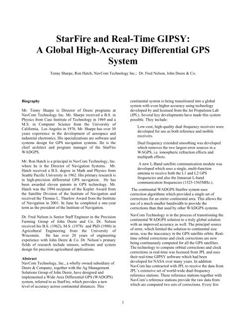
minutes a set of orbital corrections are computed for eachGPS satellite. At a more rapid rate, every few seconds, aset of clock corrections are computed for each GPSsatellite.Currently the Inmarsat L-B<strong>and</strong> communication channelprovides both the continental WADGPS corrections <strong>and</strong>the global <strong>Real</strong>-<strong>Time</strong> <strong>GIPSY</strong> (RTG) corrections. Thesoftware within the <strong>StarFire</strong> equipment is beingtransitioned to use the new RTG corrections. These globalcorrections provide a new level of unmatched accuracyfor differential GPS.The Starfire system was developed by John Deerespecifically for agriculture applications. With theavailability of very accurate position information on aglobal basis, many other applications are now beingaddressed.IntroductionFigure 1 shows an overview of the <strong>StarFire</strong> WADGPSarchitecture. At a conceptual level, it is similar to otherwide-area dGPS systems such as the Federal AviationAdministration’s Wide Area Augmentation System(WAAS), Europe’s EGNOS, <strong>and</strong> Japan’s MSAS.However, a significant difference is the use of dualfrequencyreceivers rather than the single-frequencyreceivers. The use of dual-frequency receivers allows thedirect removal of ionospheric refraction effects <strong>and</strong>,therefore, only a few reference sites are needed to achievethe high accuracy results.GPSGPSL-b<strong>and</strong>CommunicationSatelliteGPSGPSdGPSCorrectionsL<strong>and</strong> EarthStation UplinkUser Equipment on Ag MachinesProcessing HubsNetwork of GPS Reference SitesFigure 1. Overview of the <strong>StarFire</strong> WADGPS System2
The seven reference sites used in the US network areshown in Figure 1. Separate sets of reference receivers aredeployed elsewhere which are used to generateindependent sets of WADGPS corrections around theworld. There are 4 reference stations in the <strong>StarFire</strong>European Network, 5 in the Australian Network <strong>and</strong> 3 inthe South American Network. Each of the networks ofreference <strong>and</strong> monitor sites sends dual-frequency code<strong>and</strong> carrier-phase measurements from all receivers for allsatellites in view, as well as system integrity information,to two redundant processing hubs via terrestrial <strong>and</strong>satellite communication links. The processing hubscombine the measurements from all of the sites in eachregion <strong>and</strong> generates a single set of wide-area correctionsfor each region based upon the refraction correctedmeasurements. The corrections are sent, via l<strong>and</strong>-lines, tothe l<strong>and</strong>-earth station for the geostationary, L-b<strong>and</strong>communications satellite where they are uplinked forbroadcast to users throughout each region.These separate continental WADGPS systems are in theprocess of being transitioned into a single GlobalDifferential GPS (GDGPS) system which will provide anunprecedented level of accuracy worldwide. Thecommunications satellites now provide both the regionalcorrections <strong>and</strong> the more accurate global corrections.The <strong>StarFire</strong> user equipment receives the correctionsbroadcast from the communications satellite, applies themto its own observed, refraction corrected pseudoranges<strong>and</strong> performs a navigation solution. The resulting dGPSposition, velocity <strong>and</strong> time are output from the userequipment to other subsystems on the platform to supportmapping <strong>and</strong> control system requirements.Reference/Monitor Site Processing Hub Satellite UplinkFigure 2. <strong>StarFire</strong> CONUS Ground Reference Network<strong>StarFire</strong> Ground Reference NetworksFigure 2 shows the overall topology of the <strong>StarFire</strong>Ground Reference Network (GRN) for CONUS. It iscomprised of seven reference/monitor sites, tworedundant processing hubs <strong>and</strong> an uplink facility for thegeostationary communications satellite.Each of the reference/monitor sites is configured with anidentical set of equipment including:3
a) two redundant NCT2000D GPS reference receiverswhich send a full set of dual frequency observables forall satellites in view to both of the redundantprocessing hubs,b) a fully packaged production <strong>StarFire</strong> user equipmentunit which serves as an independent monitor receiver,c) communications equipment (routers, ISDN modems),d) a remotely controlled power switch <strong>and</strong> UPS module.The main communication lines used to link the referencesites with the processing hubs are frame relay privatevirtual circuits (orange <strong>and</strong> blue lines in Figure 2). Eachframe relay circuit is backed up with an ISDN dial up linewhich is activated automatically from the processing hubin the event any frame relay connection fails. The sameimplementation is used for the communication lines to<strong>and</strong> from the hubs <strong>and</strong> the uplink facility.The <strong>StarFire</strong> user equipment units located at each of thereference sites, called monitor units, operateindependently. They receive the broadcast correctionstream from the communications satellite, performdifferential GPS navigation <strong>and</strong> report their positioningresults back to the processing hubs using the samecommunication lines as the reference receivers.In addition to the dGPS positioning results, the monitordata includes the received signal strength of the L-b<strong>and</strong>communications satellite, packet error statistics, age ofdifferential corrections, signal strengths for the receivedGPS satellites, PDOP <strong>and</strong> other operating parameters.This data, from all of the GRN sites, is continuouslymonitored by an Alert Service processor whichautomatically generates E-mail <strong>and</strong> pager messages toon-call network service engineers in the event of a dGPSservice failure.AmericasEuropeAsia PacificMolineRedondoN.A. WCTEurope WCTS.A. WCTAustralia WCTFigure 3 The Four Regional WADGPS NetworksThe three other regional networks are shown togetherwith the CONUS network in Figure 3. The structure <strong>and</strong>operation of the three additional WADGPS regionalnetworks are almost exact copies of the structure <strong>and</strong>operation of the CONUS network. However, thecommunication of the data between the reference <strong>and</strong>4
monitor receivers takes advantage of the Internet <strong>and</strong>, insome cases, satellite communication links as well. Theprocessing hubs for these regional networks is co-locatedThe network of global reference stations, used to provideboth orbit <strong>and</strong> clock corrections for all satellites at alltimes, does not currently share any of the regionalnetwork locations. Eventually, all of the regional sites willbe incorporated into the global network of referencestations. Currently only the global reference sites operatedby JPL for NASA, identified by the red flags in Figure 4,are used in computing the global corrections. TheInternet <strong>and</strong> satellite links are used to bring the dualfrequencymeasurements from these global referenceswith the CONUS processing hubs at the Redondo <strong>and</strong>Moline locations <strong>and</strong> shares the communication links <strong>and</strong>redundant structure of the CONUS network.back to the processing hubs at Redondo <strong>and</strong> Moline.Since the hubs receive data from more than 30 referencesites, the corrections are robust <strong>and</strong> the loss of data fromone or more sites would not affect the accuracysignificantly. Like the other networks, duplicateprocessing at both Redondo <strong>and</strong> Moline are used so thatan automatic switch of the data uploaded to thecommunication satellites occurs if a failure is detected inone of the hubs.Figure 4 The Global NASA Network of Reference StationsHub Processing SoftwareThe algorithm used at the processing hubs to compute the<strong>StarFire</strong> WADGPS corrections for the regional networksis called the Wide Area Correction Transform (WCT).The WCT uses the following inputs:a) dual frequency observables (CA code pseudoranges,L1 carrier phase, P2 code pseudoranges <strong>and</strong> L2 carrierphase) for all of the GPS satellites tracked at the GRNreference receivers, delivered at 1Hz in real time,b) broadcast ephemeris records from the GRN referencereceivers delivered in real time,c) a configuration file defining the precise location(±2cm) of each of the GRN reference receiverantennas as determined from network solutions basedon the IGS worldwide control stations.The dual frequency observables are used to formsmoothed, refraction corrected pseudoranges which arefree of ionosphere delay <strong>and</strong>, due to extended smoothingwith the carrier phase, virtually free of multipath. Theseare then normalized with respect to receiver clock offsets<strong>and</strong> modeled site troposphere delays. Finally, thenormalized pseudoranges for each satellite are combinedin a weighted average to form a single, wide areapseudorange correction for that satellite. A similarprocess is performed using the finite difference of the5
carrier phase to generate pseudorange rate corrections.The ensemble of these corrections for all satellites in viewis formatted into a tightly packed, binary message <strong>and</strong>sent from the hub to the uplink facility for broadcast onthe geostationary communications satellite.Because the WCT uses refraction corrected pseudoranges,the resulting WADGPS corrections are free of the errorscaused by spatial decorrelation of ionosphere delayswhich are inherent in single frequency corrections. Whendual frequency mobile receivers are used which employthe same refraction corrected techniques, a single set ofcorrections can be used across the entire continentalservice area with uniform, high accuracy.Two major advantages result from having oneconsolidated set of corrections for the entire service area:a) B<strong>and</strong>width requirements on the geostationarycommunications satellite are minimized. This resultsin a significant cost savings since the price of leasedsatellite channels is roughly proportional to thebroadcast power required which is directlyproportional to the b<strong>and</strong>width required.b) The correction computation algorithm, including thefinal weighting, is done at a centralized facility (atthe processing hubs) instead of being performed bythe user equipment based on location dependentmodels. This enables improvements <strong>and</strong> upgrades tothe WCT to be made, in most cases, withoutrequiring changes to the algorithms in the mobileuser equipment. This is a significant logistic benefitwhen, as is the case now with <strong>StarFire</strong>, thous<strong>and</strong>s ofuser equipment units are deployed across thecontinental U.S.The processing software used to generate the globalcorrections requires the same set of inputs as is used forthe regional processing. However, the specific data comesfrom the global NASA network of reference receivers.Further, the real-time <strong>GIPSY</strong> (RTG) processing softwareused within the processing hubs at Redondo <strong>and</strong> Moline isthat developed by JPL <strong>and</strong> licensed to <strong>NavCom</strong>. Changesto the software to improve the efficiency of thetransmitted corrections have been made by JPL incoordination with <strong>NavCom</strong>. Orbit corrections for eachsatellite are generated <strong>and</strong> transmitted every five minutes<strong>and</strong> clock corrections for each satellite are generated <strong>and</strong>transmitted ever two seconds. The correction data is sentvia the l<strong>and</strong>-lines to the uplink facility <strong>and</strong> is broadcastfrom the communications satellites using the samechannels as the regional corrections. Because of theefficiency of the correction data both the regionalcorrections <strong>and</strong> the global corrections can be sent over thesame channel <strong>and</strong> the user equipment can select whichcorrection stream to use.<strong>StarFire</strong> User EquipmentFigure 5 shows the major components of the <strong>StarFire</strong> userequipment.a) A multi-function antenna assembly is used which iscapable of receiving the L1 <strong>and</strong> L2 GPS frequenciesas well as the Inmarsat receive frequency b<strong>and</strong>. Thegain pattern of this antenna is designed to be relativelyconstant even at lower elevation angles. This allowsfor an efficient link budget when the unit is operated athigher latitudes where the elevation of thegeostationary communications satellite is low.b) An L-b<strong>and</strong> receiver was developed to acquire, track,downconvert, sample <strong>and</strong> demodulate the <strong>StarFire</strong> datastream broadcast from the geostationarycommunications satellite. The receiver is frequencyagile across the Inmarsat receive b<strong>and</strong> under softwarecontrol.c) A state-of –the-art, dual frequency GPS receivermodule, designed <strong>and</strong> produced by <strong>NavCom</strong>, providesthe most important enabling technology in the userequipment.Connections for the external interfaces of the <strong>StarFire</strong>user equipment are provided through a sealed 10-pinconnector. Power connections include main, battery <strong>and</strong>programming voltage inputs. Data interfaces includeCAN Bus <strong>and</strong> RS232 serial.An alternate packaging of the <strong>StarFire</strong> equipment isshown in Figure 6. This package uses an external remotetri-b<strong>and</strong> antenna to receive the two GPS frequencies <strong>and</strong>the L-b<strong>and</strong> communication satellite signal.The NCT2000D Dual Frequency GPS EngineThe NCT2000D is a compact, high-performance, dualfrequency GPS engine aimed at OEM applications. In the<strong>StarFire</strong> user equipment, it is mounted inside the lowerhousing <strong>and</strong> interfaces to the digital board of the L-b<strong>and</strong>receiver via an RS232 serial port. The <strong>StarFire</strong> correctionsare input from the L-b<strong>and</strong> receiver <strong>and</strong> 1, 5, or 10Hz PVTdata is output to the L-b<strong>and</strong> receiver for transmission viathe external interfaces (RS-232 <strong>and</strong> CAN Bus).The NCT2000D has ten, full dual frequency channels <strong>and</strong>two WAAS channels. It produces GPS observables of thehighest quality suitable for use in the most dem<strong>and</strong>ingapplications including millimeter level static surveys.Key features of the NCT2000D include:a) A patented multipath reduction technique is built intothe digital signal processing ASICs of the receiver.6
This greatly reduces the magnitude of multipathdistortions on both the CA code <strong>and</strong> P2 codepseudorange measurements. When combined withextended, dual frequency code-carrier smoothing,MultifunctionantennaSealed package suitable forharsh environmentsL-b<strong>and</strong>comm.receiverNCT2000DdualfrequencyGPS engineExternal Data Interfaces:CAN Bus, RS-232Figure 5. Major Components of the <strong>StarFire</strong> User Equipmentmultipath errors in the code pseudorangemeasurements are virtually eliminated.The measurement processing of the NCT2000D softwareversion in the <strong>StarFire</strong> user equipment is designed to beb) A patented technique is used to achieve near optimalrecovery of the P code from the anti-spoofing Y-coderesulting in more robust tracking of the P2/L2 signals.c) The compact size (4” x 3”x 1”) of the NCT2000Dallows it to be readily integrated into the <strong>StarFire</strong>package.d) A high resolution 1pps output signal, synchronized toGPS time, is provided by the NCT2000D. This signalis used by the L-b<strong>and</strong> communications receiver tocalibrate its local oscillator, which aids the acquisitionof the <strong>StarFire</strong> correction signal. This technique hasalso been patented by <strong>NavCom</strong>.7
Figure 6. Alternate packaging of the <strong>StarFire</strong> UserEquipmentfully compatible with the both the <strong>StarFire</strong> regionalcorrection signal <strong>and</strong> the global correction signal. Eitherof the correction streams can be used depending upon thecontrol software within the <strong>StarFire</strong> unit. Dual frequencycode <strong>and</strong> carrier phase measurements are used to formsmoothed, refraction corrected code pseudoranges. Whenthe regional correction stream is used, the smoothed codemeasurements are adjusted with the <strong>StarFire</strong> regionalcorrections <strong>and</strong> used in a weighted least-squares fix togenerate PVT estimates.The global corrections are processed a bit differentlywithin the NCT2000D receiver. Specifically, a greaterreliance is put on the carrier phase measurements <strong>and</strong> afloating ambiguity estimate is made of the whole-cycleambiguities. All of the measurement data from allsatellites is used to make this ambiguity estimate asaccurate as possible. In addition, a constrained estimate ofthe tropospheric refraction is made using the data from allthe satellites. This constrained solution removes some ofthe unmodeled tropospheric refraction effects. Theresulting PVT estimates are output at either 1, 5, or 10Hzunder software control.<strong>StarFire</strong> Positioning Accuracy <strong>and</strong> Test ResultsFigures 7, 8 <strong>and</strong> 9 shows the position accuracy obtainedby using the global <strong>StarFire</strong> corrections for 24 hours atthree test sites around the world. The one-sigma accuracyper horizontal axis rarely exceeds 10 cm. As expected, theaccuracy is not dependent upon geographical location.The accuracy obtained by using the <strong>StarFire</strong> globalcorrections in within a <strong>StarFire</strong> receiver cannot be equaledby any other global system. Furthermore very few, if any,regional networks can match these results.Agricultural Applications of the <strong>StarFire</strong> System<strong>StarFire</strong> equipment is currently used in a number ofagricultural applications including yield mapping, fielddocumentation, operator assisted steering <strong>and</strong> automaticsteering.In terms of sheer numbers of units, yield mapping is thesingle largest agricultural application of <strong>StarFire</strong>. In thisRedondo Beach, California, <strong>StarFire</strong> Monitor Receiver24 Hour Positioning Results336Position Error (meters)210-1-2East North UpStd. Dev. (m.) 0.07 0.05 0.13302418126DGPS Status <strong>and</strong> Number of SVsDeDnNsatsQual-30 4 8 12 16 20 24GPS <strong>Time</strong> (seconds in week)0Figure 7 <strong>StarFire</strong> Results in California using Global Corrections8
Zweibrucken, Germany, <strong>StarFire</strong> Monitor Receiver24 Hour Positioning Results336Position Error (meters)210-1East North UpStd. Dev. (m.) 0.07 0.04 0.0830241812DGPS Status <strong>and</strong> Number of SVsDeDnNsatsQual-26-300 4 8 12 16 20 24GPS <strong>Time</strong> (seconds in week)Figure 8 <strong>StarFire</strong> Results in Germany using Global CorrectionsMelbourne, Australia, <strong>StarFire</strong> Monitor Receiver24 Hour Positioning Results336Position Error (meters)210-1-2East North UpStd. Dev. (m.) 0.09 0.06 0.17302418126DGPS Status <strong>and</strong> Number of SVsDeDnNsatsQual-300 4 8 12 16 20 24GPS <strong>Time</strong> (seconds in week)9
Figure 9 <strong>StarFire</strong> Results in Australia using Global Correctionsapplication, the precise real-time position of a harvestingmachine, typically a combine, is recorded simultaneouslywith data from yield sensors which measure the amountof crop being taken. Figure 10 shows a <strong>StarFire</strong> unitmounted on a John Deere combine.Table 1. Position Accuracies Needed for AutomaticSteering for Selected Field Operationsto the excellent short term accuracy. In automatic steeringapplications the machine is steered to follow a preplannedcourse by a control system comprised of positionsensors, a computerized control algorithm, electrohydraulicor electro-mechanical steering controls <strong>and</strong>feedback sensors. The operator may take control of themachine manually to execute turns or unplannedmaneuvers but the repetitive, row-following operationsare done automatically. This leaves the operator free forother tasks such as monitoring the performance of atowed implement.Typical position accuracies needed for yield mapping,assisted <strong>and</strong> automatic steering are shown in Table 1Applications Beyond AgricultureFigure 10. <strong>StarFire</strong> Unit on a John Deere CombineAfter the field has been harvested, the recorded data ismoved from the combine to a personal computer <strong>and</strong>processed into a color coded map with statistics whichshow the yield distribution as a function of position.Operator assisted steering involves presentation of agraphic display, which shows a driver the currentdeviation of the machine from a planned course. Thedriver manually controls the machine to minimize thedisplayed deviation.Even before the implementation of the global corrections<strong>and</strong> the resulting accuracy, the use of the <strong>StarFire</strong> systemin automatic steering systems was increasing rapidly dueField OperationFertilizer application (anhydrous)Fertilizer application (bulk)Heavy TillageFinish TillagePlantingSpraying (pre-emerge w/o markers)CultivatingHarvestingStalk ChoppingPositionAccuracy(2σ horiz.)12" (30 cm.)18" (46 cm.)12" (30 cm.)18" (46 cm.)10" (25 cm.)18" (46 cm.)2" (5 cm.)10" (25 cm.)10" (25 cm.)The enhanced accuracy of the <strong>StarFire</strong> system makes it anatural fit for many applications outside of agricultureincluding:L<strong>and</strong> survey <strong>and</strong> geographic information systems,Construction equipment guidance <strong>and</strong> control,Marine survey <strong>and</strong> resource exploration,Hydrographic mapping <strong>and</strong> dredging systems,L<strong>and</strong> transportation tracking applications, such asrailway monitoring, which require high levels ofposition accuracy.ConclusionThe <strong>StarFire</strong> system, including its major subsystems, hasbeen described in some detail. Key enabling technicaldevelopments have been identified <strong>and</strong> discussed.Position plots <strong>and</strong> statistics showing excellent accuracyperformance have been presented. The use of <strong>StarFire</strong>System in agriculture has been described. Its use in manyother fields is beginning to be exploited. There is no otherglobal positioning system which is as economical to use<strong>and</strong> as precise as the <strong>StarFire</strong> system using the globalcorrection stream broadcast over Inmarsat regionalsatellites.AcknowledgementsThe <strong>StarFire</strong> system would not have been developedwithout the sponsorship, vision <strong>and</strong> perseverance of theAdvanced Management Systems group of John Deere.The contributions of Mr. Terrence Pickett are especiallynoteworthy.10