NCT-2030M - NavCom Technology Inc.
NCT-2030M - NavCom Technology Inc.
NCT-2030M - NavCom Technology Inc.
- No tags were found...

Create successful ePaper yourself
Turn your PDF publications into a flip-book with our unique Google optimized e-Paper software.
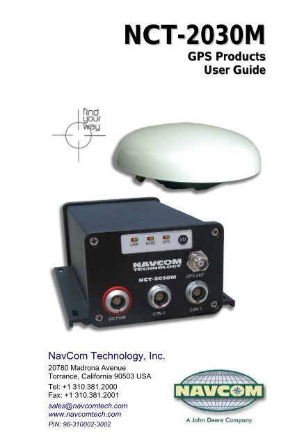
<strong>NCT</strong>-<strong>2030M</strong>GPS ProductsUser Guide<strong>NavCom</strong> <strong>Technology</strong>, <strong>Inc</strong>.20780 Madrona AvenueTorrance, California 90503 USATel: +1 310.381.2000Fax: +1 310.381.2001sales@navcomtech.comwww.navcomtech.comP/N: 96-310002-3002
<strong>NCT</strong>-<strong>2030M</strong> User Guide – Rev. DThis page is left blank intentionally
<strong>NCT</strong>-<strong>2030M</strong> User Guide – Rev. DTable of ContentsList of Figures ..........................................................ivList of Tables ............................................................vNotices ...........................................................viCopyright .................................................................... viTrademarks ................................................................ viFCC Notice ................................................................ viiUser Notice................................................................ viiLimited Warranty .......................................................viiiStarFire Licensing................................................... ixUSG FAR.................................................................... ixGlobal Positioning System ......................................... ixRevision History.......................................................xiUse of this Document .............................................xiiRelated Documents ....................................................... xiiStarUtil User Guide.................................................... xiiTechnical Reference Manual.....................................xiiiRINEXUtil User Guide ...............................................xiiiIntegrators Toolkit......................................................xiii<strong>NavCom</strong> Release Notes............................................xiiiRelated Standards ........................................................ xivICD-GPS-200 ........................................................... xivRTCM-SC-104.......................................................... xivCMR, CMR+ ............................................................. xivNMEA-0183 .............................................................. xivPublicly-Operated SBAS Signals ............................. xivChapter 1 Introduction .....................................17System Overview...........................................................17GPS Sensor System .................................................17Accuracy....................................................................18Features ....................................................................19Output Data Rate.......................................................19<strong>NCT</strong> Binary Proprietary Data.....................................19NMEA-0183 Data ......................................................20Antennae........................................................................21Standard ....................................................................21Airborne (option)........................................................21Controller .......................................................................22Applications ...............................................................24Unique Features ............................................................24i
<strong>NCT</strong>-<strong>2030M</strong> User Guide – Rev. DChapter 2 Interfacing........................................ 27Electrical Power.........................................................27Communication Ports ................................................30CAN Bus/Event .........................................................33Event .........................................................................331 PPS ........................................................................34Indicator Panel...............................................................35Chapter 3 Installation ....................................... 37Standard Antenna .....................................................37GPS Sensor...............................................................39Block Diagram ...........................................................41Communication Port Connectivity .............................42GPS Antenna Connector...........................................44Chapter 4 Configuration .................................. 47Factory Default Settings ................................................48Message Descriptions ...............................................503 rd Party Controller Configuration Settings................51Chapter 5 Safety Instructions.......................... 53Transport ...................................................................53Maintenance..............................................................53External Power Source..............................................53Safety First ................................................................54A GPS Module Specifications ............................. 55Features ....................................................................55Time-To-First-Fix.......................................................56Dynamics...................................................................56Measurement Performance.......................................57User programmable output rates ..............................57User programmable output rates ..............................58Data Latency .............................................................581PPS .........................................................................58Connector Assignments ............................................58Input/Output Data Messages.....................................59LED Display Functions (Default) ...............................59Satellite Based Augmentation System Signals .........60Physical and Environmental......................................60B Antenna Specifications.................................... 61Radiation Pattern.......................................................63C StarFire .......................................................... 65Description.................................................................65Infrastructure .............................................................66Reliability ...................................................................67ii
<strong>NCT</strong>-<strong>2030M</strong> User Guide – Rev. DHow to Access the StarFire Service ..........................68D Event Input Configuration................................71Glossary ..........................................................73iii
<strong>NCT</strong>-<strong>2030M</strong> User Guide – Rev. DList of FiguresFigure 1: <strong>NCT</strong>-<strong>2030M</strong> Supplied Equipment............. 23Figure 2: Universal Power Adapter.......................... 28Figure 3: AC Power Cord ........................................ 28Figure 4: Optional DC Power Cable ........................ 29Figure 5: <strong>NCT</strong>-<strong>2030M</strong> Front View............................ 31Figure 6: <strong>NavCom</strong> Serial Cable............................... 32Figure 7: <strong>NCT</strong>-<strong>2030M</strong> Back View............................ 33Figure 8: <strong>NCT</strong>-<strong>2030M</strong> Indicator Panel..................... 35Figure 9: Standard GPS/L-band Antenna................ 37Figure 10: <strong>NCT</strong>-<strong>2030M</strong> Base Plate Dimensions...... 40Figure 11: <strong>NCT</strong>-<strong>2030M</strong> Block Diagram ................... 41Figure 12: Radio Port Configuration, StarUtil .......... 42Figure 13: Communication Port Connections.......... 43Figure 14: StarUtil NMEA Message List.................. 48Figure 15: StarUtil Rover Navigation Setup............. 49Figure 16: Antenna Dimensions .............................. 62Figure 17: AN-2004T Radiation Pattern .................. 63Figure 18: Optional Airborne Antenna Dimensions .64Figure 19: StarFire Network................................. 70Figure 20: Event Cable Wiring Diagram .................. 71Figure 21: PPS & Event Latch Configuration .......... 72Figure 22: Event Latch Output Rate Configuration.. 72Figure 23: DTE to DCE RS-232 Pin Assignments... 76iv
<strong>NCT</strong>-<strong>2030M</strong> User Guide – Rev. DList of TablesTable 1: Supplied Equipment...................................23Table 2: External Power Cable Pin-Out ...................27Table 3: Optional DC Cable Pin Assignments .........29Table 4: Serial Cable Pin-Outs ................................31Table 5: Link LED Indication ....................................36Table 6: Base Station Indication ..............................36Table 7: GPS Light Indication ..................................36Table 8: Acceptable Cable Lengths .........................44Table 9: Factory Setup Proprietary Msgs COM 2 ....50Table 10: Standard Antenna ....................................61Table 11: Event Wiring Connections........................71v
<strong>NCT</strong>-<strong>2030M</strong> User Guide – Rev. DNotices<strong>NCT</strong>-<strong>2030M</strong> GPS Products User GuideP/N 96-310002-3002Revision DMarch 2008Serial Number:Date Delivered:Purchased From:Copyright© 2008 by <strong>NavCom</strong> <strong>Technology</strong>, <strong>Inc</strong>.All rights reserved. No part of this work or thecomputer program(s) described herein may bereproduced, stored, or transmitted by any means,without the expressed written consent of the copyrightholders. Translation in any language is prohibitedwithout the expressed written consent of the copyrightholders.Trademarks‘find your way’, ‘<strong>NavCom</strong> Globe’ and ‘NAVCOMTECHNOLOGY’ logos are trademarks of <strong>NavCom</strong><strong>Technology</strong>, <strong>Inc</strong>. StarFire is a registered trademarkof Deere & Company. All other product and brandnames are trademarks or registered trademarks oftheir respective holders.vi
<strong>NCT</strong>-<strong>2030M</strong> User Guide – Rev. DFCC NoticeThis device complies with Part 15 of the FCC Rules.Operation is subject to the following two conditions:1. This device may not cause harmfulinterference, and2. This device must accept any interferencereceived, including interference that maycause undesired operation.The GPS sensor has been tested in accordance withFCC regulations for electromagnetic interference.This does not guarantee non-interference with otherequipment. Additionally, the GPS sensor may beadversely affected by nearby sources ofelectromagnetic radiation.The Global Positioning System is under the control ofthe United States Air Force. Operation of the GPSsatellites may be changed at any time and withoutwarning.User Notice<strong>NavCom</strong> <strong>Technology</strong>, <strong>Inc</strong>. shall not be responsible forany inaccuracies, errors, or omissions in informationcontained herein, including, but not limited to,information obtained from third party sources, such aspublications of other companies, the press, orcompetitive data organizations.This publication is made available on an “as is” basisand <strong>NavCom</strong> <strong>Technology</strong>, <strong>Inc</strong>. specifically disclaimsall associated warranties, whether express or implied.In no event will <strong>NavCom</strong> <strong>Technology</strong>, <strong>Inc</strong>. be liable fordirect, indirect, special, incidental, or consequentialdamages in connection with the use of or reliance onthe material contained in this publication, even ifadvised of the possibility of such damages. <strong>NavCom</strong><strong>Technology</strong>, <strong>Inc</strong>. reserves the right to makevii
<strong>NCT</strong>-<strong>2030M</strong> User Guide – Rev. Dimprovements or changes to this publication and theproducts and services herein described at any time,without notice or obligation.Limited Warranty<strong>NavCom</strong> <strong>Technology</strong>, <strong>Inc</strong>., warrants that its productswill be free from defects in workmanship at the time ofdelivery. Under this limited warranty, parts found tobe defective or defects in workmanship will berepaired or replaced at the discretion of <strong>NavCom</strong><strong>Technology</strong>, <strong>Inc</strong>., at no cost to the Buyer, providedthat the Buyer returns the defective product to<strong>NavCom</strong> <strong>Technology</strong>, <strong>Inc</strong>. in the original suppliedpackaging and pays all transportation charges,duties, and taxes associated with the return of theproduct. Parts replaced during the warranty perioddo not extend the period of the basic limited warranty.This provision does not extend to any <strong>NavCom</strong><strong>Technology</strong>, <strong>Inc</strong>. products, which have beensubjected to misuse, accident or improper installation,maintenance or application, nor does it extend toproducts repaired or altered outside the <strong>NavCom</strong><strong>Technology</strong>, <strong>Inc</strong>. production facility unless authorizedin writing by <strong>NavCom</strong> <strong>Technology</strong>, <strong>Inc</strong>.This provision is expressly accepted by the buyer inlieu of any or all other agreements, statements orrepresentations, expressed or implied, in fact or inlaw, including the implied warranties ofmerchantability and fitness for a particular purposeand of all duties or liabilities of <strong>NavCom</strong> <strong>Technology</strong>,<strong>Inc</strong>. To the buyer arising out of the use of the goods,and no agreement or understanding varying orextending the same will be binding upon <strong>NavCom</strong><strong>Technology</strong>, <strong>Inc</strong>. unless in writing, signed by a dulyauthorizedofficer of <strong>NavCom</strong> <strong>Technology</strong>, <strong>Inc</strong>.This limited warranty period is one (1) year from dateof purchase.viii
<strong>NCT</strong>-<strong>2030M</strong> User Guide – Rev. DStarFire LicensingThe StarFire signal requires a subscription thatmust be purchased in order to access the service.Licenses are non-transferable, and are subject to theterms of the StarFire Signal License agreement.For further details on the StarFire Signal Network,its capabilities, terms and conditions visitwww.navcomtech.com or send an email inquiry tosales@navcomtech.comUSG FARTechnical Data Declaration (Jan 1997)The Contractor, <strong>NavCom</strong> <strong>Technology</strong>, <strong>Inc</strong>., herebydeclares that, to the best of its knowledge and belief,the technical data delivered herewith underGovernment contract (and subcontracts, ifappropriate) are complete, accurate, and comply withthe requirements of the contract concerning suchtechnical dataGlobal Positioning SystemSelective availability (S/A code) was disabled on 02May 2000 at 04:05 UTC. The United Statesgovernment has stated that present GPS users usethe available signals at their own risk. The USGovernment may at any time end or changeoperation of these satellites without warning.The U.S. Department of Commerce LimitsRequirements state that all exportable GPS productscontain performance limitations so that they cannotbe used to threaten the security of the United States.Access to satellite measurements and navigationresults will be limited from display and recordableoutput when predetermined values of velocity andaltitude are exceeded. These threshold values are farix
<strong>NCT</strong>-<strong>2030M</strong> User Guide – Rev. Din excess of the normal and expected operationalparameters of the <strong>NCT</strong>-<strong>2030M</strong> GPS Sensor.x
<strong>NCT</strong>-<strong>2030M</strong> User Guide – Rev. DRevision HistoryRev D (Mar 2008)Format changeAdded Revision HistoryAdded airborne antenna optionAdded <strong>NCT</strong>-<strong>2030M</strong> blockdiagramUpdated text and graphicspertaining to StarFireAdded specs for Ultra-RTKxi
<strong>NCT</strong>-<strong>2030M</strong> User Guide – Rev. DUse of this DocumentThis User Guide is intended to be used by someonefamiliar with the concepts of GPS and satellitesurveying equipment. Note indicates additional informationto make better use of the product.This symbol means Reader BeCareful. Indicates a caution, care,and/or safety situation. The user mightdo something that could result inequipment damage or loss of data.This symbol means Danger. You are ina situation that could cause bodilyinjury. Before you work on anyequipment, be aware of the hazardsinvolved with electrical and RF circuitryand be familiar with standard practicesfor preventing accidents.Revisions to this User Guide can be obtained in adigital format fromhttp://www.navcomtech.com/Support/Related DocumentsStarUtil User GuideP/N 96-310008-3001Describes the operation and use of <strong>NavCom</strong>’sWindows based control program (included on CD)xii
<strong>NCT</strong>-<strong>2030M</strong> User Guide – Rev. DTechnical Reference ManualP/N 96-3120001-3001Describes the control and output data messageformats utilized by this instrument (for customerprogramming purposes; included on CD)RINEXUtil User GuideP/N 96-310021-2101Describes the conversion program used no <strong>NavCom</strong>proprietary output data message formats to RINEXver 2.10 observation and navigation files (forcustomer programming purposes; included on CD)Integrators ToolkitP/N 97-310020-3001Provides additional instruction and tools fordeveloping control programs for this instrument (notincluded in the packaging material; contacthttp://www.navcomtech.com/Support/ for a copy)<strong>NavCom</strong> Release NotesDescribes software updates for <strong>NavCom</strong> products.Current and archived Release Notes are available onthe <strong>NavCom</strong> web site:http://www.navcomtech.com/Support/DownloadCenter.cfm?category=releasenotes.<strong>NavCom</strong> Customer Support provides softwareupdates described in the Release Notes. Submit arequest for software updates via the Request Supportweb page.xiii
<strong>NCT</strong>-<strong>2030M</strong> User Guide – Rev. DRelated StandardsICD-GPS-200NAVSTAR GPS Space Segment / Navigation UserInterfaces Standard. ARINC Research Corporation;2250 E. Imperial Highway; El Segundo, California90245RTCM-SC-104Recommended Standards For Differential GNSSService. Radio Technical Commission For MaritimeServices; 1800 N. Kent St, Suite 1060; Arlington,Virginia 22209CMR, CMR+Compact Measurement Record; Trimble NavigationLimited; 935 Stewart Drive; Sunnyvale, CA 94085NMEA-0183National Marine Electronics Association Standard ForInterfacing Marine Electronic Devices. NMEANational Office; 7 Riggs Avenue; Severna Park,Maryland 21146Publicly-Operated SBAS SignalsRTCA/DO-229DThe Radio Technical Commission for Aeronautics(RTCA) develops consensus-basedrecommendations regarding communications,navigation, surveillance, and air traffic management(CNS/ATM) system issues.RTCA. 1828 L Street, NW, Suite 805, Washington,DC 20036.xiv
<strong>NCT</strong>-<strong>2030M</strong> User Guide – Rev. DThese organizations implement the RTCA/DO-229Dstandard set by RTCA:WAAS (Wide Area Augmentation System)U.S. Department of Transportation. Federal AviationAdministration. 800 Independence Ave, SW,Washington, DC 20591EGNOS (European Geostationary Navigation OverlayService)European Space Agency. 8, 10 rue Mario-Nikis,F-75738 Paris Cedex 15, France.MSAS (MTSAT Satellite-based AugmentationSystem)Japan Civil Aviation Bureau. Ministry of Transport.Kasumigaseki 2-1-3, Chiyoda-ku, Tokyo 100, Japan.GAGAN (GPS Aided Geo Augmented Navigation)Indian Space Research Organization. AntarikshBhavan, New Bel Road, Bangalore - 560 094, India.xv
<strong>NCT</strong>-<strong>2030M</strong> User Guide – Rev. DThis page is left blank intentionallyxvi
<strong>NCT</strong>-<strong>2030M</strong> User Guide – Rev. DChapter 1 .............................. IntroductionSystem OverviewGPS Sensor SystemThe <strong>NCT</strong>-<strong>2030M</strong> GPSsensor deliversunmatched accuracy tothe precise positioningcommunity, includingsystem integrators inneed of a cost-effective,high performance differential GPS sensor.The <strong>NCT</strong>-<strong>2030M</strong> GPS sensor delivers centimeterlevel position accuracy via external RTK 1 correctionformats. The receiver is capable of <strong>NCT</strong>-RTK, RTCM(code and phase), and CMR/CMR+ DGPS operatingmethods. The operating software is also capable ofsupporting an external radio modem.Where WAAS, EGNOS, MSAS, or GAGANcorrections are available, the receiver can achievehalf-meter real-time horizontal positioning via twodedicated Satellite Based Augmentation System(SBAS) channels.The <strong>NCT</strong>-<strong>2030M</strong> integrated sensor consists of: 24-channel, dual-frequency, precision GPSreceiver 2 separate SBAS channels, RTCA/DO-229Dcompliant (WAAS/EGNOS/MSAS/GAGAN)The <strong>NCT</strong>-<strong>2030M</strong> is packaged for mobility. It can beused for Geographic Information System (GIS), aerialand hydrographic surveying, and post-processed1 Separate Software Option Required1-17
<strong>NCT</strong>-<strong>2030M</strong> User Guide – Rev. Ddual-frequency surveys. No external data-loggingdevice is required since the receiver has 64MB of onboardstorage memory.The <strong>NCT</strong>-<strong>2030M</strong> is equipped with additional featuresallowing interconnectivity with a wide variety ofantennas, vehicle data busses and otherinstrumentation to match specific applications andconfigurations. The <strong>NCT</strong>-<strong>2030M</strong> includes a 1PPSoutput port and a combined Event/CAN Bus interfaceport.<strong>NavCom</strong> provides a long-term upgrade path so the<strong>NCT</strong>-<strong>2030M</strong> can grow if needs change. This unit canbe configured as the <strong>NavCom</strong> SF-2050M StarFire 1receiver or the RT-3020M RTK receiver with built-inRTK 2 spread spectrum radio. Contactsales@navcomtech.com for information.Refer to Table 1, later in this chapter, for thecomplete list of supplied equipment.AccuracyWhen WAAS, EGNOS, MSAS, or GAGAN(RTCA/DO-229D compliant) SBAS correction signalsare used, the system provides
<strong>NCT</strong>-<strong>2030M</strong> User Guide – Rev. D
<strong>NCT</strong>-<strong>2030M</strong> User Guide – Rev. D Channel Status (0x86) Correction Data (mirror data; 0xEC) Event/Marker (0xB4) Measurement Quality (0xB1 and 0xB5)These data can be integrated in real-time positioningapplications or post-processed against any number ofsoftware applications designed to handle <strong>NCT</strong> orRINEX raw data. A Technical Reference Manual isavailable on <strong>NavCom</strong>’s web site, which describes theattributes of each of the input/output records (seeRelated Documents in the fore-matter).NMEA-0183 DataThe <strong>NCT</strong>-<strong>2030M</strong> is capable of outputting severalstandard NMEA-0183 data strings (see RelatedStandards in the fore-matter) and one proprietarydata sting. Each data is headed with GP. Theproprietary data sting is denoted with a $P<strong>NCT</strong>header.Standard: ALM – GPS Almanac Data GGA – GPS Fix Data GLL – Geographic Position – Lat / Lon GSA – GNSS DOP & Active Satellites GST – GNSS Pseudorange Error Statistics GSV – GNSS Satellites In View RMC – Recommended Minimum Specific GNSSData VTG – Course Over Ground & Ground Speed ZDA – Time & Date1-20
<strong>NCT</strong>-<strong>2030M</strong> User Guide – Rev. DProprietary (header $P<strong>NCT</strong>): SET – Solid Earth TideDescribed in the Technical Reference Manual (seeRelated Documents in the fore-matter)AntennaeStandardThe standard integratedantenna (PN: 82-001002-3002)tracks all GPS,WAAS/EGNOS/MSAS/GAGANand StarFire 1 signals. Ourcompact GPS antenna has excellent trackingperformance and a stable phase center for GPS L1and L2. This antenna is listed in the NOAA GPSAntenna Calibration tables, as NAVAN2004T. Therobust housing assembly features a standard 5/8”BSW thread for mounting directly to a surveyor’spole, tripod, or mast and is certified to 70,000 feet(see Specifications for restrictions).Airborne (option)<strong>Inc</strong>luded with the VueStarsystem.The airborne integratedantenna (PN: 82-001002-3001) tracks all GPS, WAAS/EGNOS/MSAS/GAGANand StarFire 1 signals. Our compact GPS antennahas excellent tracking performance and a stablephase center for GPS L1 and L2. This antenna islisted in the NOAA GPS Antenna Calibration tables,as NAVAN2008T. The robust housing assemblyfeatures a flat mounting surface with four mounting1 StarFire Service Requires a Product Upgrade1-21
<strong>NCT</strong>-<strong>2030M</strong> User Guide – Rev. Dholes and a downward facing TNC connector. Thisantenna is also certified to 70,000 feet (seeSpecifications for restrictions).ControllerThe <strong>NCT</strong>-<strong>2030M</strong> GPS sensor is designed for use withan external controller solution connected via one oftwo serial COM ports.This may be accomplished using a PC, Tablet PC orPersonal Digital Assistant (PDA) and a softwareprogram which implements the rich control languagedefined for <strong>NavCom</strong> GPS products. Refer to theuser’s guide of your controller solution for furtherinformation. <strong>NavCom</strong> lists several applicationsoftware solutions on our website:http://www.navcomtech.com/Support/ApplicationSoftware.cfmIn addition, <strong>NavCom</strong> provides a Windows basedsoftware utility, called StarUtil, with the receiver.The StarUtil User Guide, P/N 96-310008-3001, isavailable on-line athttp://www.navcomtech.com/Support/DownloadCenter.cfm?category=manuals.1-22
<strong>NCT</strong>-<strong>2030M</strong> User Guide – Rev. D<strong>Inc</strong>luded ItemsFigure 1: <strong>NCT</strong>-<strong>2030M</strong> Supplied EquipmentTable 1: Supplied Equipment<strong>NCT</strong>-<strong>2030M</strong> GPS Sensor1(P/N 92-310056-3004)LEMO 7-Pin to DB9S Data Cable, 6 ft2(P/N 94-310059-3006)Compact L1/L2 Tri-Mode GPS Antenna3(P/N 82-001002-3002)GPS Antenna Cable, 12 ft4(P/N 94-310058-3012)LEMO 4-Pin Universal AC/DC Power Adapter 12vdc, 2A5(P/N 82-020002-5001)CD-Rom containing User Guides, brochures, software6 utilities, and technical papers.(P/N 96-310006-3001)<strong>NCT</strong>-<strong>2030M</strong> User’s Guide {Not Shown}7(P/N 96-310002-3002 Hard Copy)8 American 2-Pin AC power Cord, 10 ft {Not Shown}1-23
<strong>NCT</strong>-<strong>2030M</strong> User Guide – Rev. DApplicationsThe <strong>NCT</strong>-<strong>2030M</strong> GPS sensors meet the needs of alarge number of applications including, but not limitedto: Vehicle Navigation Machine Control Structural Monitoring GIS Survey Hydrography OEM Integration<strong>NavCom</strong> lists several application software solutionson our website:http://www.navcomtech.com/Support/ApplicationSoftware.cfmUnique FeaturesThe <strong>NCT</strong>-<strong>2030M</strong> GPS sensor has many uniquefeatures:• Positioning FlexibilityThe <strong>NCT</strong>-<strong>2030M</strong> is capable of using WAAS, EGNOS,MSAS, GAGAN (RTCA/DO-229D compliant) codecorrections via two internal Satellite BasedAugmentation System (SBAS) channels. The<strong>NCT</strong>-<strong>2030M</strong> automatically configures to use the mostsuitable correction source available and changes asthe survey dictates (this feature can be overridden).1-24
<strong>NCT</strong>-<strong>2030M</strong> User Guide – Rev. D• Data SamplingGPS L1 and L2 raw measurement data is up to 5Hzin the standard configuration. An optional upgradeallows 10, 25, and 50Hz raw measurement data viaeither of the two serial ports.The PVT (Position, Velocity, & Time) data is output atup to 5 Hz in the standard configuration. An optionalupgrade allows 10Hz and 25Hz position updates forhighly dynamic applications.• GPS PerformanceThe <strong>NCT</strong>-<strong>2030M</strong> utilizes <strong>NavCom</strong>’s <strong>NCT</strong>-2100 GPSengine, which incorporates several patentedinnovations. The engine’s industry leading receiversensitivity provides more than 50% signal to noiseratio advantage over competing technologies. Thisresults in improved real time positioning, proventhrough independent tests, when facing variousmultipath environments.• Rugged DesignUnits have been tested to conform to MIL-STD-810Ffor low pressure, solar radiation, rain, humidity, saltfog,sand, and dust.The rugged design of the <strong>NCT</strong>-<strong>2030M</strong> systemcomponents provides protection against the harshenvironments common to areas such as constructionsites, offshore vessels, and mines.1-25
<strong>NCT</strong>-<strong>2030M</strong> User Guide – Rev. DThis page is left blank intentionally1-26
<strong>NCT</strong>-<strong>2030M</strong> User Guide – Rev. DChapter 2 ................................. InterfacingThis chapter details the <strong>NCT</strong>-<strong>2030M</strong> GPS sensorconnectors, LED display, appropriate sources ofelectrical power, and how to interface thecommunication ports.Electrical PowerA front panel 4-pin LEMO female connector provideselectrical power to the <strong>NCT</strong>-<strong>2030M</strong>. Pin assignmentsare given in Table 2; see Figure 4 for pin location onthe connector.Pin1234Table 2: External Power Cable Pin-OutDescriptionReturnPower Input 10 to 30 VDC; 8WPins 1 and 2 connect to same internal point in the<strong>NCT</strong>-<strong>2030M</strong>. Likewise, pins 3 and 4 connect to thesame internal point. The supplied power cable isconstructed using 26 AWG wire. Power cable longer than 5m (15ft) must makefull use of all four power pins.2-27
<strong>NCT</strong>-<strong>2030M</strong> User Guide – Rev. DThe <strong>NCT</strong>-<strong>2030M</strong> is supplied with a universal AC/DC,12V, 2A power adapter (P/N 82-020002-5001).Figure 2: Universal Power Adapter Replacement AC power cords areavailable through small applianceretailers (Radio Shack, Walmart, BestBuy, etc.)Figure 3: AC Power Cord2-28
<strong>NCT</strong>-<strong>2030M</strong> User Guide – Rev. DP/N 94-310060-3010 is an optional 10ft (3m)unterminated power cable fitted with a LEMO plugtype (Mfr. P/N FGG.1K.304.CLAC50Z), with red strainrelief. The wiring color code and pin assignments arelabeled on the cable assembly and provided below.Table 3: Optional DC Power Cable Pin AssignmentsColor Signal Pin NoBlack 1ReturnBrown2Red 3PowerOrange4Figure 4: Optional DC Power CableThe GPS sensor is protected from reverse polaritywith an inline diode. It will operate on any DC voltagebetween 10 and 30 VDC, 4 watts (maximum). Voltages less than 10VDC will turn theunit off. To turn the unit on, powermust be in the 10 to 30 VDC range.Press and hold the I/O switch in formore than 3 seconds.To set the receiver to power up assoon as power is applied to the DCInput port, refer to the StarUtil UsersGuide, Power Management or the2-29
<strong>NCT</strong>-<strong>2030M</strong> User Guide – Rev. DTechnical Reference Manual, 0x32Power Mode Configuration.Voltages in excess of 30VDC willdamage the unit. The power supplymust be well conditioned with surgeprotection. Vehicular electrical systemswhich create voltage spikes in excessof 30VDC will benefit from providingpower protection during vehicle enginepower-up. This can be accomplishedthrough a relay power-on sequenceand/or power conditioning (such as aDC to DC converter). Do not connectequipment directly to the vehiclesbattery without in-line protection (suchas a DC to DC converter).Communication PortsThe <strong>NCT</strong>-<strong>2030M</strong> provides two 7-pin female LEMOconnector communication ports labeled COM1 andCOM2 located at the bottom front of the sensor, asshown in Figure 5. Each conforms to the EIA RS-232standard with data rates from 1.2 to 115.2kbps. Theconnector pin-outs are described in Table 4. Thesupplied interface data cable (P/N 94-310059-3006)is constructed as described in Figure 6. The<strong>NCT</strong>-<strong>2030M</strong> is configured as a DCE device. Laptopand desktop computers are configured as DTEdevices, therefore a straight-through cable providesproper connectivity (PC TXD pin 2 connects to<strong>NCT</strong>-<strong>2030M</strong> RXD pin 2).2-30
<strong>NCT</strong>-<strong>2030M</strong> User Guide – Rev. DLEMOPinsTable 4: Serial Cable Pin-OutsSignal Nomenclature[DCE w/respect to DB9]DB9SPins1CTS - Clear To Send5VDC to TruBlu 1 82 RD - Receive Data 23 TD - Transmit Data 34 DTR - Data Terminal Ready 45 RTN - Return [Ground] 56 DSR - Data Set Ready 67 RTS - Request To Send 7Figure 5: <strong>NCT</strong>-<strong>2030M</strong> Front View1 TruBlu – <strong>NavCom</strong>’s Bluetooth wireless accessory2-31
<strong>NCT</strong>-<strong>2030M</strong> User Guide – Rev. DLEMO1234<strong>NavCom</strong>5Reciever67PN: 94-310059-3006RD (per DCE Standard Definition)TD (per DCE Standard Definition)DTRGNDDSRRTSCTS / 5VDCDB9S12345678907-00039-AFigure 6: <strong>NavCom</strong> Serial Cable P/N 94-310059-3006Connect pin 5 to shield of cable at both ends.2-32
<strong>NCT</strong>-<strong>2030M</strong> User Guide – Rev. DCAN Bus/EventFigure 7: <strong>NCT</strong>-<strong>2030M</strong> Back ViewThe <strong>NCT</strong>-<strong>2030M</strong> provides a balanced (differential)2-wire CAN Bus technology interface, ISO11898 -24Vcompliant. The CAN interface uses an asynchronoustransmission scheme employing serial binaryinterchange widely used in the automotive industry.The data rate is defined as 250Kbps maximum withtermination resistors at each end of the cable. Thisport/connector is shared with the Event Input. CAN Bus specifications are diverse.Drivers for the existing hardware mustbe tailored to the specificmanufacturer’s equipment beinginterfaced to. For further information,e-mail <strong>NavCom</strong> Customer Support atcustomersupport@<strong>NavCom</strong>tech.com .EventThe <strong>NCT</strong>-<strong>2030M</strong> accepts an event input pulse tosynchronize external incidents requiring precise GPStime tagging, such as aerial photography. For2-33
<strong>NCT</strong>-<strong>2030M</strong> User Guide – Rev. Dexample, the action of a camera’s aperture createsan input pulse to the Event port. The <strong>NCT</strong>-<strong>2030M</strong>outputs position and time information relative to eachphotograph taken.Specifications: 50 Ohm input impedance 3VDC > Input Voltage, High < 6VDC 0VDC < Input Voltage, Low < 1.2VDC Minimum pulse width, 100nsec Rising or Falling edge SynchronizationConnecting the shared EVT MKR/CAN BUS portrequires a five core, 5mm diameter, cable fitted with aLEMO plug, type FGG.0K.305.CLAC50Z, plus strainrelief, <strong>NavCom</strong> P/N 94-310062-3003. An event latch interface unit may benecessary if the input device pulse isunable to drive the input.Detailed specifications of the EventInput, cable wiring, and configurationmay be found in Appendix D of thisUser Guide.1 PPSA pulse is available from the <strong>NCT</strong>-<strong>2030M</strong> at an outputrate of once per second. This pulse can be used for avariety of Time/ Mark applications where relativetiming is required.Specifications: 12.5ns relative accuracy Better than 100ns absolute accuracy 50 Ohm, TTL level Pulse width, default 100mS, range 10 – 999mS2-34
<strong>NCT</strong>-<strong>2030M</strong> User Guide – Rev. DPulse delay, default 0mS, range 0 – 999mSRising or Falling Edge SynchronizationA BNC female connector provides the 1PPS outputpulse. A 3ft (0.9m) long, BNC male to BNC malecable (P/N 94-310050-3003) is available from<strong>NavCom</strong>.Indicator PanelFigure 8: <strong>NCT</strong>-<strong>2030M</strong> Indicator PanelThe indicator panel provides a quick status view ofbase station correction type (when the <strong>NCT</strong>-<strong>2030M</strong> isoperated as a Base Station), GPSnavigation/operating mode, and the On/Off (I/O)switch, respectively. Each set of indicators has threeLEDs.To power the unit on or off, depress the I/O switch formore than 3 seconds. All LEDs illuminate for a periodof 3-5 seconds during power-up of the GPS sensor.• Link LEDs The Link LEDs are softwareconfigurable via the x3f proprietarycommand. Only the factory defaultconfiguration is described here.2-35
<strong>NCT</strong>-<strong>2030M</strong> User Guide – Rev. DTable 5: Link LED IndicationLINKStatus<strong>NCT</strong>-<strong>2030M</strong> operating as a Base Station• Base LEDsBASE StatusTable 6: Base Station IndicationThe following BASE LEDs reflect the type of RTK 1corrections when the <strong>NCT</strong>-<strong>2030M</strong> is operated as aBase StationRTK - <strong>NCT</strong> ProprietaryCMRRTCM, 20,21; 18,19• GPS LEDsTable 7: GPS Light IndicationGPSStatusPower is offPower is on, No satellites trackedTracking satellites, position not available yetNon-differential positioningCode based differential positioningDual frequency Phase positioning The GPS LEDs blink at the PVTpositioning rate (1, 5, 10, or 25Hz)1 Separate Software Option Required2-36
<strong>NCT</strong>-<strong>2030M</strong> User Guide – Rev. DChapter 3 .................................InstallationThis chapter provides guidance on hardwareinstallation for optimum performance.Standard AntennaThe 5/8 inch BSW threaded antenna mount has adepth of 16mm (0.63 inch).It is possible to remove the 5/8 inch BSW threadedalloy insert to reveal a secondary means of mountingthe antenna, a 1-14UNS-2B thread with a depth of16mm (0.63 inch). This is a typical marine industrymount for navigation antennas.The BSW insert is secured in-place with anadhesive, and its removal will change theshock and vibration sustainabilitycharacteristics of the antenna mount.Figure 9: Standard GPS/L-band AntennaDo not loosen or remove the eight Phillipsscrews on the base of the antenna formounting purposes. This will VOID thewarranty and compromise the environmentalseal of the antenna, leading to internaldamage.3-37
<strong>NCT</strong>-<strong>2030M</strong> User Guide – Rev. D Antenna placement is critical to good systemperformance. Avoid antenna shading by buildings,rooftop structures, foliage, hills/mountains, etc. Locate the antenna where it has a clear view ofthe sky, to an elevation angle of 7º if possible.Obstructions below 15º elevation generally arenot a problem, though this is dependent onsatellite availability for the local region. Avoid placing the antenna where more than 90ºazimuth of the sky is obstructed. When more than90º of azimuth is shaded, it is often still possiblefor the reciever to navigate, however, poorsatellite geometry (due to satillte shading) willprovide poor positioning results. Even 10º ofshading can have a negative effect onperformance, though this generally is not thecase. Avoid placing the antenna on or near metal orother electrically reflective surfaces. Do not paint the antenna enclosure with ametallic-based paint. Avoid placing the antenna near electrical motors(elevator, air conditioner, compressor, etc.) Do not place the antenna too close to other activeantennas. The wavelength of L2 is 0.244m and L1is 0.19m. The minimum acceptable separationbetween antennas is 1m (39 in), which provides6dB of isolation. For 10 dB of isolation, separatethe GPS antennas by 2.5m, and for 13dB ofisolation (recommended) separate the antennasby 5m. Active antennas (those with LNA’s or amplifiers)create an electrical field around the antenna.These radiated emissions can interfere with othernearby antennas. Multiple GPS antennas in close3-38
<strong>NCT</strong>-<strong>2030M</strong> User Guide – Rev. Dproximity to each other can create multipath andoscillations between the antennas. These add toposition error or the inability to process thesatellite signals. Most antenna’s have better gain when the satelliteis high in elevation. Expect tracking performanceto fade as the satellite lowers in elevation. It is notunusual to see 10dB difference in antenna gain(which translates into signal strength) throughoutthe entire elevation tracking path. Map obstructions above the horizon using acompass and inclinometer. Use satellite predictionsoftware with a recent satellite almanac to assessthe impact on satellite visibility at that location(available on <strong>NavCom</strong>’s web site).GPS SensorMount the <strong>NCT</strong>-<strong>2030M</strong> GPS sensor to a flat surface.Shock isolators suitable for 1.8kg (4lbs) may benecessary for environments with high vibration, i.e.Earth moving equipment or aircraft installation.The <strong>NCT</strong>-<strong>2030M</strong> can be installed in a backpack formobile surveying applications.Do not place the sensor in a confined space or whereit may be exposed to excessive heat, moisture, orhumidity.There are no user serviceable partsinside the <strong>NCT</strong>-<strong>2030M</strong> GPS sensor.Removing the screws that secure thefront end and rear end plates will voidthe equipment warranty.3-39
<strong>NCT</strong>-<strong>2030M</strong> User Guide – Rev. DFigure 10: <strong>NCT</strong>-<strong>2030M</strong> Base Plate Dimensions3-40
<strong>NCT</strong>-<strong>2030M</strong> User Guide – Rev. DBlock DiagramThe <strong>NCT</strong>-<strong>2030M</strong> has three user configurable physicalcommunications ports (two external and one internal)and several logical communications ports. To aid indistinguishing these ports, please refer to the blockdiagram below.Figure 11: <strong>NCT</strong>-<strong>2030M</strong> Block Diagram These user configurable physical portsare Com1, Com2, andRadio/Diagnostic. The Com ports aredescribed in the next section. TheRadio/Diagnostic port connects to aninternal UHF radio in <strong>NavCom</strong>’s RTlineof products and is not used, norshould it be assigned as a logical portin any of the <strong>NCT</strong>-<strong>2030M</strong> products.3-41
<strong>NCT</strong>-<strong>2030M</strong> User Guide – Rev. DFigure 12: Radio Port Configuration, StarUtilCommunication Port ConnectivityConnect the supplied LEMO 7-Pin connector of theserial cable (P/N 94-310059-3006) to COM 2 (factorydefault Control Port) of the <strong>NCT</strong>-<strong>2030M</strong>. Connect theDB9 end to the control device. Some devices may require an additionaladapter. The receiver is configured as a DCEdevice. COM 2 is the <strong>NCT</strong>-<strong>2030M</strong> logical control portby default. COM 1 can be configured as thecontrol port by using the appropriate <strong>NavCom</strong>proprietary commands or StarUtil. However,there are caveats to Logical / Physical portassignments.The Control Port is a logical input/output portand can not share the physical port with anyother logical port. The Control Port typicallyhandles the most data and requires baudrates in excess of 19.2K baud, particularly in3-42
<strong>NCT</strong>-<strong>2030M</strong> User Guide – Rev. Dmulti-hertz measurement and navigationapplications. Though Com 1 is physicallycapable of operating at 115K baud, thethroughput from the <strong>NCT</strong>-2100D to the IOP islimited to 19.2K baud (refer to Figure 11).Thus, the recommendation to maintain Com 2as the Control port for multi-hertz applications.In the Rover, the NMEA Port is an outputlogical port and may share the data physicalport (non-Control) with RTCM, CMR, or <strong>NCT</strong>RTK input corrections. In the Base Station,the NMEA port can not share the data portwith any RTCM, CMR, or <strong>NCT</strong> RTK outputcorrections.Refer to the Technical Reference Manual foravailable port configuration settings.Figure 13: Communication Port Connections3-43
<strong>NCT</strong>-<strong>2030M</strong> User Guide – Rev. DGPS Antenna ConnectorThe connector used on the <strong>NCT</strong>-<strong>2030M</strong> is a TNCfemale, labeled GPS on the front panel of the sensoras shown in Figure 5. The <strong>NCT</strong>-<strong>2030M</strong> GPS connectorprovides 5 VDC, 50mA max power theantenna preamplifier. Do notdisconnect the antenna when the GPSunit is powered on.The system is supplied with 12ft (3.6m) of RG58/Ucable (P/N 94-310058-3012). The cable is fitted witha right angle male TNC connector and a straight maleTNC connector respectively.The cable length between the antenna and<strong>NCT</strong>-<strong>2030M</strong> should not exceed 7dB loss at 1.575GHzfor optimum performance, though the system maytolerate up to 10dB of cable loss with minimalperformance. Lower elevation satellite trackingsuffers the most with more than 7dB insertion loss.CableTypeTable 8: Acceptable Cable LengthsAtten.(dB) per100 Ft.CableLengthin FeetLossin dBAtten.(dB)per100 mCableLengthinMetersLossin dBRG-58C 19.605 36.00 7.06 64.32 11.00 7.08RG-142 16.494 43.00 7.09 54.12 13.00 7.04RG-213 9.564 74.00 7.08 31.38 22.50 7.06RG-223 17.224 41.00 7.06 56.51 12.50 7.06LMR600 3.407 207.00 7.05 11.18 63.00 7.04LMR400 5.262 133.00 7.00 17.26 41.00 7.08LMR240 10.127 70.00 7.09 33.23 21.00 6.98LMR195 14.902 47.00 7.00 48.89 14.00 6.85In-line amplifiers suitable for all GPS frequencies maybe used to increase the length of the antenna cable,3-44
<strong>NCT</strong>-<strong>2030M</strong> User Guide – Rev. Dbut care should be exercised that trackingperformance is not degraded due to multipleconnections, noise from the amplifier, and possibleingress of moisture and dust to the in-line amplifier.In-line amplifier or splitter devices must pass DCpower from the receiver to the antenna, or source theappropriate voltage and current to the antenna (seeAntenna Specifications). In-line amplifiers may alsoover-saturate the receiver front-end if improperlyused. The antenna cable can degrade signalquality if incorrectly installed, or the cableloss exceeds <strong>NavCom</strong> specifications.Take care not to kink, stretch, distort, ordamage the antenna cable. Do not placethe cable adjacent to cables carryingelectrical power or radio frequencies. Inthese instances, attempt to cross cablesat 90º angles in an effort to reduce crosscouplingof RF signals.Where the GPS antenna is exposed tosources of electromagnetic dischargesuch as lightning, install a properlygrounded in-line electrical surgesuppressor between the GPS sensor andantenna. Install protective devices incompliance with local regulatory codesand practices. Protective devices mustpass DC power from the receiver to theantenna.3-45
<strong>NCT</strong>-<strong>2030M</strong> User Guide – Rev. DThis page is left blank intentionally3-46
<strong>NCT</strong>-<strong>2030M</strong> User Guide – Rev. DChapter 4 ...............................ConfigurationThe <strong>NCT</strong>-<strong>2030M</strong> has a rich interface and detailedcontrol language, allowing each unit to be individuallytailored to a specific application.There are essentially 3 methods available toconfigure and control the <strong>NCT</strong>-<strong>2030M</strong>: StarUtil – This program is a <strong>NavCom</strong> developedutility designed to configure and view many (butnot all) of the <strong>NCT</strong>-<strong>2030M</strong> functions. In additionto its setup capabilities, StarUtil can capture andlog data, upload new software and licenses to thethree internal processors, and query and displayvarious receiver performance functions. Thoughit is developed as an Engineering tool, it has itsown place in the commercial market as well. Theprogram is provided on the CD with the<strong>NCT</strong>-<strong>2030M</strong>.3 rd part controller – Some manufacturers havealready integrated <strong>NavCom</strong>’s control features intheir bundled hardware and software solution kitsin a variety of applications including GIS,Machine Control, Aerial Photogrammetry, Land &Oceanographic Survey, Agriculture, and Militaryproducts. Information on these applications isavailable from the <strong>NavCom</strong> web site andcustomer service.User Program – User’s may develop uniqueoperating programs to control the <strong>NCT</strong>-<strong>2030M</strong>(potentially in conjunction with other devices orutilities). To facilitate this effort, <strong>NavCom</strong> has twotools additional tools available: the IntegratorsTool Kit (ITK) and the Technical ReferenceManual (TRM). Information on these tools isavailable from the <strong>NavCom</strong> web site andcustomer service.4-47
<strong>NCT</strong>-<strong>2030M</strong> User Guide – Rev. DFactory Default Settings• COM1Configuration - Data portRate – 19.2KbpsOutput of NMEA messages GGA & VTGscheduled @ 1Hz rate Though the output rate defaults to1Hz, the data output rate can bechanged to On Change. Making thisselection in the NMEA output list willbetter reflect the navigation rateselected in the Rover Setup screen.Figure 14: StarUtil NMEA Message List4-48
<strong>NCT</strong>-<strong>2030M</strong> User Guide – Rev. DFigure 15: StarUtil Rover Navigation SetupThis port is normally used to output data to otherdevices or machines that can make immediate use ofthe precise positioning data available from the<strong>NCT</strong>-<strong>2030M</strong>. COM1 also serves as the DGPScorrection input/output port when <strong>NCT</strong>, CMR, orRTCM RTK 1 correction services are in use.• COM2Configuration - Control PortRate – 19.2KbpsThis port is normally used to input and outputproprietary messages used for navigation andreceiver setup. Table 9 describes the defaultmessages needed to best initiate surveying with1 Separate Software Option Required4-49
<strong>NCT</strong>-<strong>2030M</strong> User Guide – Rev. Dminimal effort.The user has full control over the utilized messagetypes and their associated rates via either StarUtil ora third party software/utility.Table 9: Factory Setup Proprietary Messages COM 2Msg Rate Description44 On Change Almanac81 On Change Ephemeris86 On Change Channel StatusA0 On Change Alert MessageAE 600 Seconds Identification BlockB0 On Change Raw Measurement DataB1 On Change PVT Solution The term “On Change” indicates thatthe <strong>NCT</strong>-<strong>2030M</strong> will output thespecified message only when theinformation in the message changes.On occasion, there may be an epochwithout a message block output.Message DescriptionsThe following message descriptions are fully definedin the Technical Reference Manual (see RelatedDocuments)44 Packed Almanac:Data corresponding to each satellite in the GPSconstellation, including: GPS Week number ofcollected almanac, GPS Time of week [inseconds] of collected almanac, almanacreference week, almanac reference time,almanac source, almanac health, pages 1-25,and sub-frames 4 and 5.4-50
<strong>NCT</strong>-<strong>2030M</strong> User Guide – Rev. D81 Packed Ephemeris:Individual satellite tracking information including:GPS Week number of collected ephemeris, GPSTime of week [in seconds] of collectedephemeris, IODC, and sub-frame 1, 2, and 3data.86 Channel Status:Receiver channel status information containing:the GPS week, GPS Time of Week, <strong>NCT</strong>-2100Engine status, number of satellitesviewed/tracked, PDOP, tracked satellite identity,satellite elevation and azimuth, C/No for the L1and L2 signals, and correction age for eachsatellite.A0 Alert Text Message:Details message receipt and processing.AE Identification Block:Details the receiver software versions (<strong>NCT</strong>-2100, and IOP) and digital serial numbers.B0 Raw Measurement Data:Raw Measurement Data Block containing: theGPS Week, GPS Time of Week, Time SlewIndicator, Status, Channel Status, CAPseudorange, L1 Phase, P1-CA Pseudorange,P2-CA Pseudorange, and L2 Phase. This datastream is repeated for each individual trackedsatellite.B1 PVT (Position, Velocity, and Time):Provides: GPS Week number, satellites used,latitude, longitude, navigation mode, and DOPinformation.3 rd Party Controller Configuration SettingsPlease refer to the third party controller solutionmanual/user guide if your <strong>NCT</strong>-<strong>2030M</strong> GPS sensor ispart of an integrated solution.4-51
<strong>NCT</strong>-<strong>2030M</strong> User Guide – Rev. DThis page is left blank intentionally4-52
<strong>NCT</strong>-<strong>2030M</strong> User Guide – Rev. DChapter 5 .................... Safety InstructionsThe <strong>NCT</strong>-<strong>2030M</strong> GPS sensor is designed for precisenavigation and positioning using the GlobalPositioning System. Users must be familiar with theuse of portable GPS equipment, the limitationsthereof and these safety instructions prior to use ofthis equipment.TransportAlways carry the <strong>NavCom</strong> equipment in a case. Thecase must be secured during transport to minimizeshock and vibration.Utilize all original packaging when transporting viarail, ship, or air.MaintenanceThe <strong>NavCom</strong> equipment may be cleaned using a newlint free cloth moistened with pure alcohol.Connectors must be inspected, and if necessarycleaned before use. Always use the providedconnector protective caps to minimize moisture anddirt ingress.Inspect cables regularly for kinks and cuts as thesemay cause interference and equipment failure.Damp equipment must be dried at a temperature lessthan +40°C (104°F), but greater than 5°C (41°F) atthe earliest opportunity.External Power SourceIf the <strong>NCT</strong>-<strong>2030M</strong> is used with the optional externalpower cable (P/N 94-310060-3010), it must beconnected to the chosen external power solution inaccordance with Chapter 2 Interfacing\ElectricalPower. It is important that the external power source5-53
<strong>NCT</strong>-<strong>2030M</strong> User Guide – Rev. Dallow sufficient current draw for proper operation.Insufficient supplied current will cause damage toyour external power source.If your chosen external power source is a disposablebattery, please dispose of the battery in accordancewith your local regulations.Safety FirstThe owner of this equipment must ensure that allusers are properly trained prior to using theequipment and are aware of the potential hazardsand how to avoid them.Other manufacturer’s equipment must be used inaccordance with the safety instructions issued by thatmanufacturer. This includes other manufacturer’sequipment that may be attached to <strong>NavCom</strong><strong>Technology</strong>, <strong>Inc</strong>. manufactured equipment.Always use the equipment in accordance with localregulatory practices for safety and health at work.There are no user serviceable parts inside the<strong>NCT</strong>-<strong>2030M</strong> GPS sensor. Accessing the inside of theequipment will void the equipment warranty.Take care to ensure the <strong>NCT</strong>-<strong>2030M</strong> does not comeinto contact with electrical power installations, the unitis securely fastened and there is protection againstelectromagnetic discharge in accordance with localregulations.5-54
<strong>NCT</strong>-<strong>2030M</strong> User Guide – Rev. DA.................... GPS Module SpecificationsThe technical specifications of this unit are detailedbelow. <strong>NavCom</strong> <strong>Technology</strong>, <strong>Inc</strong>. is constantlyimproving, and updating our technology. For thelatest technical specifications for all products go to:http://www.navcomtech.com/Support/These GPS sensors are fitted with an internal Lithiumcoin cell battery used to maintain GPS time whenpower is removed from the unit. This allows fastersatellite acquisition upon unit power up. The cell hasbeen designed to meet over 10 years of service lifebefore requiring replacement at a <strong>NavCom</strong> approvedmaintenance facility.Features“All-in-view” tracking with 26 channels(12 L1 GPS + 12 L2 GPS + 2 SBAS)Centimeter level position accuracy via externalRTK 1 correction formats. Capable of <strong>NCT</strong>-RTK,RTCM (code and phase), and CMR/CMR+DGPS operating methodsFully automatic acquisition of satellite broadcastcorrectionsRugged and lightweight package for mobileapplicationsL1 & L2 full wavelength carrier trackingC/A, P1 & P2 code trackingUser programmable output ratesMinimal data latency1 Separate Software Option RequiredA-55
<strong>NCT</strong>-<strong>2030M</strong> User Guide – Rev. D2 separate SBAS channels, RTCA/DO-229Dcompliant (WAAS/EGNOS/MSAS/GAGAN)Superior interference suppressionPatented multipath rejectionOutput of NMEA 0183 v3.1 messagesSelf-survey mode (position averaging)CAN bus interface1PPS OutputEvent MarkerTime-To-First-FixCold StartSatelliteAcquisitionSatelliteReacquisition< 60 Seconds (typical; withAlmanac)< 5 minutes (typical; withoutAlmanac)< 6 seconds outage time;immediate reacquisition (< 1second)< 30 seconds software, typical;with outage time < 65 seconds> 65 outage time requires fullacquisition processDynamicsAcceleration:Speed:Altitude:*Restricted by export lawsup to 6g< 515 m/s*< 60,000 ft*A-56
<strong>NCT</strong>-<strong>2030M</strong> User Guide – Rev. DMeasurement PerformanceReal-time RTCA/DO-229D Standard SBAS Accuracy(WAAS/EGNOS/MSAS/GAGAN)Position (H):Position (V):Velocity:
<strong>NCT</strong>-<strong>2030M</strong> User Guide – Rev. DUser programmable output ratesPVTRaw data1, 2, 5Hz Standard10 & 25Hz Optional1, 2, 5Hz Standard10, 25, & 50Hz OptionalData LatencyPVTRaw data< 20 ms at all nav rates< 20 ms at all rates1PPSAccuracy:12.5ns (Relative; UserConfigurable)Connector AssignmentsData Interfaces:2 serial ports from 1200 bps to 115.2 kbpsCAN Bus I/FEvent MarkerI/P1PPSA-58
<strong>NCT</strong>-<strong>2030M</strong> User Guide – Rev. DInput/Output Data Messages<strong>NCT</strong> ProprietaryDataNMEA-0183Messages(Output Only)ProprietaryNMEA-0183 Type(Output Only)PVTRaw MeasurementSatellite MessagesNav QualityReceiver CommandsALM, GGA, GLL, GSA, GST,GSV, RMC, VTG, ZDASETCode Corrections RTCM 1 or 9WAAS/EGNOS/MSAS/GAGANRTK Correction <strong>NCT</strong> Proprietary 1Data (I/O) RTCM 18,19 or 20, 21CMR+/CMR (Msg. 0, 1, 2) See Related Standards at the front ofthis manual for information on thevarious data formatsLED Display Functions (Default)LinkBase StationGPSN/A in Standard <strong>NCT</strong>-<strong>2030M</strong>Configuration(User Programmable)N/A in Standard <strong>NCT</strong>-<strong>2030M</strong>Configuration(User Programmable)Position Quality1 Separate Software Option RequiredA-59
<strong>NCT</strong>-<strong>2030M</strong> User Guide – Rev. DSatellite Based Augmentation System SignalsRTCA/DO-229D Standard(WAAS/EGNOS/MSAS/GAGAN)Physical and EnvironmentalSize (L x W x H): < 8.18” x 5.67” x 3.06”Weight:External Power:Input Voltage:Consumption:Connectors:I/O Ports:DC Power:RF Connector:Antenna PowerTemperature (ambient)OperatingStorage:Humidity:
<strong>NCT</strong>-<strong>2030M</strong> User Guide – Rev. DB........................... Antenna SpecificationsTable 10: Standard AntennaPart Number 82-001002-3002FrequencyL1 Phase CentrePolarizationPre–AmplifierNoise FigureImpedanceVSWR / RLBand RejectionRF Power HandlingInput Voltage1525-1585 MHzGPS L1 plus INMARSATStarFire 11217-1237 MHzGPS L258.7mmRight Hand Circular (RHCP)39dB gain (+/-2dB)
<strong>NCT</strong>-<strong>2030M</strong> User Guide – Rev. DFigure 16: PN: 82-001002-3002 Antenna Dimensions To achieve the greatest level of accuracy,the absolute phase center values must beincorporated into your processing. Phasecenter information on this antenna isfound on our web site:http://www.navcomtech.com/Support/DownloadCenter.cfm?category=antennaB-62
<strong>NCT</strong>-<strong>2030M</strong> User Guide – Rev. DRadiation Pattern24º6.5dB @ 90º32º0dB-4dB @ 5º-4.5dB @ 5º0dB07-00008-AFigure 17: AN-2004T Radiation PatternOptimal antenna performance is realized atelevations greater than 30º. There is a 10dB variation between 0º and 90ºelevation (factor 10x); therefore, lowerelevation satellites are always more difficult totrack. There is a 5dB variation between ~35º and 0ºelevation (factor >3x)B-63
<strong>NCT</strong>-<strong>2030M</strong> User Guide – Rev. DFigure 18: Optional Airborne Antenna DimensionsB-64
<strong>NCT</strong>-<strong>2030M</strong> User Guide – Rev. DC .................................................StarFireDescriptionThe StarFire 1 Network is a global system for thedistribution of SBAS corrections giving the user theability to measure his position anywhere in the worldwith exceptional reliability and unprecedentedaccuracy of better than 10cm (4 inches). Because theSBAS corrections are broadcast via INMARSAT geostationarysatellites, the user needs no localreference stations or post-processing to get thisexceptional accuracy. Furthermore, the sameaccuracy is available virtually any where on theearth's surface on land or sea from 76°N to 76°Slatitude, due to the worldwide coverage of these geostationarysatellites.1 StarFire Service Requires a Product UpgradeC-65
<strong>NCT</strong>-<strong>2030M</strong> User Guide – Rev. DInfrastructureThe system utilizes the GPS satellite system, L-Bandcommunication satellites, and a worldwide network ofreference stations to deliver real-time high precisionpositioning.To provide this unique service, <strong>NavCom</strong> has built aglobal network of dual-frequency reference stations,which constantly receive signals from the GPSsatellites as they orbit the earth. Data from thesereference stations is fed to two USA processingcenters in Torrance, California and Moline, Illinoiswhere they are processed to generate the differentialcorrections.From the two processing centers, the correction datais fed via redundant and independent communicationlinks to satellite uplink stations at Laurentides,Canada; Perth, Australia; Burum, The Netherlands;Santa Paula, California; Auckland, New Zealand; andSouthbury, Connecticut for rebroadcast via the geostationarysatellites.The key to the accuracy and convenience of theStarFire system is the source of SBAS corrections.GPS satellites transmit navigation data on twoL-Band frequencies. The StarFire referencestations are all equipped with geodetic-quality, dualfrequencyreceivers. These reference receiversdecode GPS signals and send precise, high quality,dual-frequency pseudorange and carrier phasemeasurements back to the processing centerstogether with the data messages, which all GPSsatellites broadcast.At the processing centers, <strong>NavCom</strong>'s proprietarydifferential processing techniques used to generatereal time precise orbits and clock correction data foreach satellite in the GPS constellation. Thisproprietary Wide Area DGPS (WADGPS) algorithm isC-66
<strong>NCT</strong>-<strong>2030M</strong> User Guide – Rev. Doptimized for a dual-frequency system such asStarFire in which dual-frequency ionosphericmeasurements are available at both the referencereceivers and the user receivers. It is the use of dualfrequencyreceivers at both the reference stationsand the user equipment together with the advancedprocessing algorithms, which makes the exceptionalaccuracy of the StarFire system possible.Creating the corrections is just the first part. From ourtwo processing centers, the differential correctionsare then sent to the Land Earth Station (LES) foruplink to L-Band communications satellites. Theuplink sites for the network are equipped with<strong>NavCom</strong>-built modulation equipment, whichinterfaces to the satellite system transmitter anduplinks the correction data stream to the satellite thatbroadcasts it over the coverage area. Each L-Bandsatellite covers more than a third of the earth.Users equipped with a StarFire precision GPSreceiver actually have two receivers in a singlepackage, a GPS receiver and an L-Bandcommunications receiver, both designed by <strong>NavCom</strong>for this system. The GPS receiver tracks all thesatellites in view and makes pseudorangemeasurements to the GPS satellites. Simultaneously,the L-Band receiver receives the correctionmessages broadcast via the L-Band satellite. Whenthe corrections are applied to the GPSmeasurements, a position measurement ofunprecedented real time accuracy is produced.ReliabilityThe entire system meets or exceeds a targetavailability of 99.99%. To achieve this, every part ofthe infrastructure has a built-in back-up system.All the reference stations are built with duplicatereceivers, processors and communication interfaces,C-67
<strong>NCT</strong>-<strong>2030M</strong> User Guide – Rev. Dwhich switch automatically or in response to a remotecontrol signal from the processing centers. The datalinks from the reference stations use the Internet asthe primary data link and are backed up by dedicatedcommunications lines, but in fact the network issufficiently dense that the reference stationseffectively act as back up for each other. If one orseveral fail, the net effect on the correction accuracyis not impaired.There are two continuously running processingcenters, each receiving all of the reference site inputsand each with redundant communications links to theuplink LES. The LESs are equipped with twocomplete and continuously operating sets of uplinkequipment arbitrated by an automatic fail over switch.Finally, a comprehensive team of support engineersmaintains round the clock monitoring and control ofthe system.The network is a fully automated self-monitoringsystem. To ensure overall system integrity, anindependent integrity monitor receiver, similar to astandard StarFire user receiver, is installed at everyreference station to monitor service quality. Data fromthese integrity monitors is sent to the twoindependent processing hubs in Torrance, Californiaand Moline, Illinois. Through these integrity monitorsthe network is continuously checked for overall SBASpositioning accuracy, L-Band signal strength, dataintegrity and other essential operational parameters.How to Access the StarFire ServiceStarFire is a subscription service. The user pays asubscription, which licenses the use of the service fora predetermined period of time.C-68
<strong>NCT</strong>-<strong>2030M</strong> User Guide – Rev. DSubscriptions can be purchased for quarterly,biannual or annual periods and are available via a<strong>NavCom</strong> authorized representative, or by contacting<strong>NavCom</strong> Sales Department.An authorized subscription will provide an encryptedkeyword, which is specific to the Serial Number of the<strong>NavCom</strong> receiver to be authorized. This is enteredinto the receiver using the provided controllersolution. Typically the initial license is preinstalled atthe factory, and subsequent licenses will be installedby the user.The only piece of equipment needed to use theStarFire system is a StarFire receiver. <strong>NavCom</strong>offers a variety of receivers configured for differentapplications. Details of all the StarFire receivers areavailable from the <strong>NavCom</strong> authorized localrepresentative or the <strong>NavCom</strong> website at:www.<strong>NavCom</strong>tech.comStarFire receivers include a dual-frequency GPSreceiver and an L-Band receiver integrated into asingle unit to provide the exceptional precisepositioning capability of the StarFire Network,anywhere, anytime.C-69
<strong>NCT</strong>-<strong>2030M</strong> User Guide – Rev. DFigure 19: StarFire NetworkC-70
<strong>NCT</strong>-<strong>2030M</strong> User Guide – Rev. DD ...................... Event Input ConfigurationFigure 20 details the wiring of the Event/Can cableassembly <strong>NavCom</strong> part number P/N 94-310062-3003.Refer to Chapter 2, Event for detailed electricalspecifications.Table 11 details the wiring configuration required forEvent-Hi, and Event-Lo pulse sensing.Figure 20: Event Cable Wiring DiagramTable 11: Event Wiring ConnectionsPin #SignalNameEvent Sync Wiring1 Event Lo Tie Event-Hi to Ground2 Event Hi Tie Event-Lo to Ground3 Ground N/AOnce the cable is wired to correspond with the eventpulse requirements, configure the receiver to outputthe message containing a time mark, referenced tothe time kept within the receiver, indicating when theevent is sensed (xB4).The Event Input can be triggered on the Rising orFalling edge of the input pulse. Configuration ispossible thru the StarUtil program. Figure 21 is aD-71
<strong>NCT</strong>-<strong>2030M</strong> User Guide – Rev. Dscreen capture of the program’s PPS & Event Latchwindow.Figure 21: PPS & Event Latch ConfigurationEnable the Event Latch message (0xB4) in the <strong>NCT</strong>2000 Message Output list. Set the Message Rate for0xB4 to “On Trigger”. Right-Click on the Rate areaadjacent to the B4 Message ID, and follow the menuas depicted in Figure 22. Once configured. the EventLatch Message (0xB4) is output upon recognition ofan input trigger by the receiver.Figure 22: Event Latch Output Rate ConfigurationD-72
<strong>NCT</strong>-<strong>2030M</strong> User Guide – Rev. DGlossary.yym files see meteorological files (where yy = twodigit year data was collected)..yyn files see navigation files (where yy = two digityear data was collected)..yyo files see observation files (where yy = two digityear data was collected).almanac files an almanac file contains orbitinformation, clock corrections, and atmospheric delayparameters for all satellites tracked. It is transmittedto a receiver from a satellite and is used by missionplanning software.alt see altitude.altitude vertical distance above the ellipsoid or geoid.It is always stored as height above ellipsoid in theGPS receiver but can be displayed as height aboveellipsoid (HAE) or height above mean sea level(MSL).Antenna Phase Center (APC) The point in anantenna where the GPS signal from the satellites isreceived. The height above ground of the APC mustbe measured accurately to ensure accurate GPSreadings. The APC height can be calculated byadding the height to an easily measured point, suchas the base of the antenna mount, to the knowndistance between this point and the APC.APC see antenna phase center or phase center.Autonomous positioning (GPS) a mode ofoperation in which a GPS receiver computes positionfixes in real time from satellite data alone, withoutreference to data supplied by a reference station ororbital clock corrections. Autonomous positioning istypically the least precise positioning procedure aGlossary-73
<strong>NCT</strong>-<strong>2030M</strong> User Guide – Rev. DGPS receiver can perform, yielding position fixes thatare precise to 100 meters with Selective Availabilityon, and 30 meters with S/A off.azimuth the azimuth of a line is its direction as givenby the angle between the meridian and the linemeasured in a clockwise direction from the northbranch of the meridian.base station see reference station.baud rate (bits per second) the number of bits sentor received each second. For example, a baud rate of9600 means there is a data flow of 9600 bits eachsecond. One character roughly equals 10 bits.bits per second see baud rate.bps see baud rate.BSW (British Standard Whitworth) a type of coarsescrew thread. A 5/8” diameter BSW is the standardmount for survey instruments.C/A code see Coarse Acquisition code.CAN BUS a balanced (differential) 2-wire interfacethat uses an asynchronous transmission scheme.Often used for communications in vehicularapplications.channel a channel of a GPS receiver consists of thecircuitry necessary to receive the signal for a singleGPS satellite.civilian code see Coarse Acquisition code.Coarse Acquisition code (C/A or Civilian code)the pseudo-random code generated by GPSsatellites. It is intended for civilian use and theaccuracy of readings using this code can bedegraded if selective availability (S/A) is introducedby the US Department of Defense.Glossary-74
<strong>NCT</strong>-<strong>2030M</strong> User Guide – Rev. DCOM# shortened form of the word Communications.Indicates a data communications port to/from theGPS sensor to a controller or data collection device.Compact Measurement Record (CMR) a standardformat for DGPS corrections used to transmitcorrections from a reference station to rover sensors.See Related Standards in Notices.controller a device consisting of hardware andsoftware used to communicate and manipulate theI/O functions of the GPS sensor.convergence period (StarFire) is the timenecessary for the received StarFire signalcorrections to be applied and the position filtered tooptimal performance. The convergence period istypically 30 to 45 minutes to achieve
<strong>NCT</strong>-<strong>2030M</strong> User Guide – Rev. DModem`DTERJ45 DB256 85 34 22 203 761 48 5DB912345678Straight-Through CableDCDRDTDDTRGNDDSRRTSCTSDCEDB9 DB251 82 33 24 205 76 67 48 507-00041-AFigure 23: DTE to DCE RS-232 Pin AssignmentsDGPS see Differential GPS.Differential GPS (DGPS) a positioning procedurethat uses two receivers, a rover at an unknownlocation and a reference station at a known, fixedlocation. The reference station computes correctionsbased on the actual and observed ranges to thesatellites being tracked. The coordinates of theunknown location can be computed with sub-meterlevel precision by applying these corrections to thesatellite data received by the rover.Dilution of Precision (DOP) a class of measures ofthe magnitude of error in GPS position fixes due tothe orientation of the GPS satellites with respect tothe GPS receiver. There are several DOPs tomeasure different components of the error. Note: thisis a unitless value. see also PDOP.DOP see Dilution of Precision.DTE Data Terminal Equipment. See DCE.Glossary-76
<strong>NCT</strong>-<strong>2030M</strong> User Guide – Rev. Ddual-frequency a type of GPS receiver that usesboth L1 and L2 signals from GPS satellites. A dualfrequencyreceiver can compute more preciseposition fixes over longer distances and under moreadverse conditions because it compensates forionospheric delays. The <strong>NCT</strong>-<strong>2030M</strong> is a dualfrequency receiver.dynamic mode when a GPS receiver operates indynamic mode, it assumes that it is in motion andcertain algorithms for GPS position fixing are enabledin order to calculate a tighter position fix.EGNOS (European Geostationary NavigationOverlay Service) a European satellite system usedto augment the two military satellite navigationsystems now operating, the US GPS and RussianGLONASS systems.elevation distance above or below Local VerticalDatum.elevation mask the lowest elevation, in degrees, atwhich a receiver can track a satellite. Measured fromthe horizon to zenith, 0º to 90º.ellipsoid a mathematical figure approximating theearth’s surface, generated by rotating an ellipse on itsminor axis. GPS positions are computed relative tothe WGS-84 ellipsoid. An ellipsoid has a smoothsurface, which does not match the earth’s geoidalsurface closely, so GPS altitude measurements cancontain a large vertical error component.Conventionally surveyed positions usually reference ageoid, which has an undulating surface andapproximates the earth’s surface more closely tominimize altitude errors.epoch literally a period of time. This period of time isdefined by the length of the said period.Glossary-77
<strong>NCT</strong>-<strong>2030M</strong> User Guide – Rev. DGAGAN (GPS Aided Geo Augmented Navigation)an Indian satellite system that provides a set ofcorrections for the GPS satellites, which are valid forthe Indian region. They incorporate satellite orbit andclock corrections.geoid the gravity-equipotential surface that bestapproximates mean sea level over the entire surfaceof the earth. The surface of a geoid is too irregular touse for GPS readings, which are measured relative toan ellipsoid. Conventionally surveyed positionsreference a geoid. More accurate GPS readings canbe obtained by calculating the distance between thegeoid and ellipsoid at each position and subtractingthis from the GPS altitude measurement.GIS (Geographical Information Systems) acomputer system capable of assembling, storing,manipulating, updating, analyzing and displayinggeographically referenced information, i.e. dataidentified according to their locations. GIS technologycan be used for scientific investigations, resourcemanagement, and development planning. GISsoftware is used to display, edit, query and analyzeall the graphical objects and their associatedinformation.Global Positioning System (GPS) geometrically,there can only be one point in space, which is thecorrect distance from each of four known points. GPSmeasures the distance from a point to at least foursatellites from a constellation of 24 NAVSTARsatellites orbiting the earth at a very high altitude.These distances are used to calculate the point’sposition.GMT see Greenwich Mean Time.GPS see Global Positioning System.GPS time a measure of time. GPS time is based onUTC, but does not add periodic ‘leap seconds’ toGlossary-78
<strong>NCT</strong>-<strong>2030M</strong> User Guide – Rev. Dcorrect for changes in the earth’s period of rotation.As of September 2002 GPS time is 13 secondsahead of UTC.Greenwich Mean Time (GMT) the local time of the0° meridian passing through Greenwich, England.HAE see altitude, and ellipsoid.IODC Issue of Data, Clock - The IODC indicates theissue number of the data set and thereby providesthe user with a convenient means of detecting anychange in the correction parameters. The transmittedIODC will be different from any value transmitted bythe satellite during the preceding seven days.JPL Jet Propulsion Laboratory.Kbps kilobits per second.L-Band the group of radio frequencies extendingfrom approximately 400MHz to approximately1600MHz. The GPS carrier frequencies L1(1575.4MHz) and L2 (1227.6 MHz) are in the L-Bandrange.L1 carrier frequency the primary L-Band carrierused by GPS satellites to transmit satellite data. Thefrequency is 1575.42MHz. It is modulated by C/Acode, P-code, or Y-code, and a 50 bit/secondnavigation message. The bandwidth of this signal is1.023MHz.L2 carrier frequency the secondary L-Band carrierused by GPS satellites to transmit satellite data. Thefrequency is 1227.6MHz. It is modulated by P-code,or Y-code, and a 50 bit/second navigation message.The bandwidth of this signal is 10.23MHz.lat see latitude.latitude (lat) the north/south component of thecoordinate of a point on the surface on the earth;expressed in angular measurement from the plane ofGlossary-79
<strong>NCT</strong>-<strong>2030M</strong> User Guide – Rev. Dthe equator to a line from the center of the earth tothe point of interest. Often abbreviated as Lat.LED acronym for Light Emitting Diode.LEMO a type of data or power connector.LES Land Earth Station the point on the earth’ssurface where data is up linked to a satellite.logging interval the frequency at which positionsgenerated by the receiver are logged to data files.lon see longitude.longitude (long) the east/west component of thecoordinate of a point on the surface of the earth;expressed as an angular measurement from theplane that passes through the earth’s axis of rotationand the 0° meridian and the plane that passesthrough the axis of rotation and the point of interest.Often abbreviated as Long.Mean Sea Level (MSL) a vertical surface thatrepresents sea level.meridian one of the lines joining the north and southpoles at right angles to the equator, designated bydegrees of longitude, from 0° at Greenwich to 180°.meteorological (.YYm) files one of the three filetypes that make up the RINEX file format. Where YYindicates the last two digits of the year the data wascollected. A meteorological file contains atmosphericinformation.MSAS (MTSAT Satellite-based AugmentationSystem) a Japanese satellite system that provides aset of corrections for the GPS satellites, which arevalid for the Japanese region. They incorporatesatellite orbit and clock corrections.MSL see Mean Sea Level.Glossary-80
<strong>NCT</strong>-<strong>2030M</strong> User Guide – Rev. Dmultipath error a positioning error resulting frominterference between radio waves that has traveledbetween the transmitter and the receiver by two pathsof different electrical lengths.navigation (.YYn) files one of the three file typesthat make up the RINEX file format. Where YYindicates the last two digits of the year the data wascollected. A navigation file contains satellite positionand time information.observation (.YYo) files one of the three file typesthat make up the RINEX file format. Where YYindicates the last two digits of the year the data wascollected. An observation file contains raw GPSposition information.P/N Part Number.P-code the extremely long pseudo-random codegenerated by a GPS satellite. It is intended for useonly by the U.S. military, so it can be encrypted to Y-code deny unauthorized users access.parity a method of detecting communication errors byadding an extra parity bit to a group of bits. The paritybit can be a 0 or 1 value so that every byte will add upto an odd or even number (depending on whetherodd or even parity is chosen).PDA Personal Digital Assistant.PDOP see Position Dilution of Precision.PDOP mask the highest PDOP value at which areceiver computes positions.phase center the point in an antenna where theGPS signal from the satellites is received. The heightabove ground of the phase center must be measuredaccurately to ensure accurate GPS readings. Thephase center height can be calculated by adding theheight to an easily measured point, such as the baseGlossary-81
<strong>NCT</strong>-<strong>2030M</strong> User Guide – Rev. Dof the antenna mount, to the known distance betweenthis point and the phase center.Position the latitude, longitude, and altitude of apoint. An estimate of error is often associated with aposition.Position Dilution of Precision (PDOP) a measure ofthe magnitude of Dilution of Position (DOP) errors inthe x, y, and z coordinates.Post-processing a method of differential datacorrection, which compares data logged from aknown reference point to data logged by a rovingreceiver over the same period of time. Variations inthe position reported by the reference station can beused to correct the positions logged by the rovingreceiver. Post-processing is performed after you havecollected the data and returned to the office, ratherthan in real time as you log the data, so it can usecomplex, calculations to achieve greater accuracy.Precise code see P-code.PRN (Uppercase) typically indicates a GPS satellitenumber sequence from 1 – 32.prn (Lower Case) see Pseudorandom Noise.Protected code see P-code.Proprietary commands those messages sent to andreceived from GPS equipment produced by <strong>NavCom</strong><strong>Technology</strong>, <strong>Inc</strong>. own copyrighted binary language.pseudo-random noise (prn) a sequence of data thatappears to be randomly distributed but can be exactlyreproduced. Each GPS satellite transmits a uniquePRN in its signals. GPS receivers use PRNs toidentify and lock onto satellites and to compute theirpseudoranges.Pseudorange the apparent distance from thereference station’s antenna to a satellite, calculatedGlossary-82
<strong>NCT</strong>-<strong>2030M</strong> User Guide – Rev. Dby multiplying the time the signal takes to reach theantenna by the speed of light (radio waves travel atthe speed of light). The actual distance, or range, isnot exactly the same because various factors causeerrors in the measurement.PVT GPS information depicting Position, Velocity,Time in the <strong>NCT</strong> proprietary message format.Quick Start (StarFire) a startup mode that allowsinstant
<strong>NCT</strong>-<strong>2030M</strong> User Guide – Rev. Dreal-time. The base station transmits its GPS positionto roving receivers as the receiver generates them,and the roving receivers use the base stationreadings to differentially correct their own positions.Accuracies of a few centimeters in all threedimensions are possible. RTK requires dualfrequency GPS receivers and high speed radiomodems.reference station a reference station collects GPSdata for a fixed, known location. Some of the errors inthe GPS positions for this location can be applied topositions recorded at the same time by rovingreceivers which are relatively close to the referencestation. A reference station is used to improve thequality and accuracy of GPS data collected by rovingreceivers.RHCP Right Hand Circular Polarization used todiscriminate satellite signals. GPS signals are RHCP.RINEX (Receiver Independent Exchange) is a fileset of standard definitions and formats designed to bereceiver or software manufacturer independent and topromote the free exchange of GPS data. The RINEXfile format consists of separate files, the three mostcommonly used are:the observation (.YYo) file,the navigation (.YYn) file,meteorological (.YYm) files; where YY indicatesthe last two digits of the year the data wascollected.rover any mobile GPS receiver and field computercollecting data in the field. A roving receiver’s positioncan be differentially corrected relative to a stationaryreference GPS receiver or by using GPS orbit andclock corrections from a SBAS such as StarFire.roving receiver see rover.Glossary-84
<strong>NCT</strong>-<strong>2030M</strong> User Guide – Rev. DRTCM (Radio Technical Commission for MaritimeServices) a standard format for Differential GPScorrections used to transmit corrections from a basestation to rovers. RTCM allows both real-timekinematic (RTK) data collection and post-processeddifferential data collection. RTCM SC-104 (RTCMSpecial Committee 104) is the most commonly usedversion of RTCM message.RTK see Real-time kinematic.RTG Real Time GIPSY, a processing techniquedeveloped by NASA’s Jet Propulsion Laboratory toprovide a single set of real time global corrections forthe GPS satellites.S/A see Selective Availability.SBAS (Satellite Based Augmentation System) thisis a more general term, which encompassesStarFire, WAAS, EGNOS, MSAS, and GAGANtype corrections.Selective Availability (S/A) is the deliberatedegradation of the GPS signal by encrypting the P-code and dithering the satellite clock. When the USDepartment of Defense uses S/A, the signal containserrors, which can cause positions to be inaccurate byas much as 100 meters.Signal-to-Noise Ratio (SNR) is a measure of asatellite’s signal strength.single-frequency is a type of receiver that only usesthe L1 GPS signal. There is no compensation forionospheric effects.SNR see signal-to-noise Ratio.StarFire a set of real-time global orbit and clockcorrections for GPS satellites. StarFire equippedreceivers are capable of real-time decimeterpositioningGlossary-85
<strong>NCT</strong>-<strong>2030M</strong> User Guide – Rev. D(see Appendix C).Spread Spectrum Radio (SSR) a radio that useswide band, noise like (pseudo-noise) signals that arehard to detect, intercept, jam, or demodulate makingany data transmitted secure. Because spreadspectrum signals are so wide, they can be transmittedat much lower spectral power density (Watts perHertz), than narrow band signals.SV (Space Vehicle) a GPS satellite.Universal Time Coordinated (UTC) a time standardmaintained by the US Naval Observatory, based onlocal solar mean time at the Greenwich meridian.GPS time is based on UTC.UTC see Universal Time Coordinated.WAAS (Wide Area Augmentation System) a USsatellite system that provides a set of corrections forthe GPS satellites, which are valid for the NorthAmerican region. They incorporate satellite orbit andclock corrections.WADGPS (Wide Area Differential GPS) a set ofcorrections for the GPS satellites, which are valid fora wide geographic area.WGS-84 (World Geodetic System 1984) the currentstandard datum for global positioning and surveying.The WGS-84 is based on the GRS-80 ellipsoid.Y-code the name given to encrypted P-code whenthe U.S. Department of Defense uses selectiveavailability.Glossary-86
<strong>NCT</strong>-<strong>2030M</strong> User Guide – Rev. DThis page is left blank intentionallyGlossary-87