Easterly Tunnel Dewatering Pump Station
Easterly Tunnel Dewatering Pump Station
Easterly Tunnel Dewatering Pump Station

You also want an ePaper? Increase the reach of your titles
YUMPU automatically turns print PDFs into web optimized ePapers that Google loves.
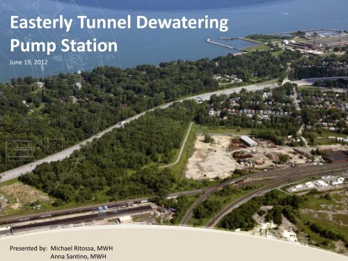
Presented by: Michael Ritossa, MWHAnna Santino, MWH<strong>Easterly</strong> <strong>Tunnel</strong> <strong>Dewatering</strong><strong>Pump</strong> <strong>Station</strong>June 19, 2012
OUTLINE• Project Technical Overview• <strong>Pump</strong> Design and Operation• Architectural and <strong>Pump</strong> <strong>Station</strong> SupportFacilities• Below Grade Facilities• Geotechnical2
Project Technical Overview3
Consent Decree Requires 98%Capture of CSO Volume by 20364Combined Sewer Area
126 CSO Locations Throughoutthe Combined Sewer Area areDriving a Systematic Approachto Mitigate Overflows
6Project Clean Lake – <strong>Easterly</strong> Service Area<strong>Easterly</strong> ServiceArea Includes:• Five <strong>Tunnel</strong>s• <strong>Dewatering</strong><strong>Pump</strong> <strong>Station</strong>• AncillaryConsolidationSewers• RegulatorImprovements<strong>Tunnel</strong><strong>Dewatering</strong><strong>Pump</strong> <strong>Station</strong>
7The Nine Mile SiteWill Be the Nexus ofSeven Projects:<strong>Easterly</strong> WWTPDWIRS $64MECT $200MDST $150METDPS $70ME. 140 th $41MSubstation $5MEuclid Creek PS $11M$541MCity ofClevelandVillage ofBratenahlECTETDPS
E. 140 th Street8Nine Mile Project Site is Accessedfrom East 140 th StreetETDPSSTAGINGAREAETDPSPROJECTSITE
3D Rendering From AboveECT Shaft 1ElectricalSubstation9
Northeast Corner10
ETDPS Project Technical Overview1. Cavern Style <strong>Pump</strong> <strong>Station</strong>• 160 MGD Firm Capacity• 230 +/- Feet Deep2. Receives Flows from 3 Storage <strong>Tunnel</strong>s:• Euclid Creek 61MG• Dugway 51MG• Shoreline 48 MG3. Delivers Flows to <strong>Easterly</strong> Interceptor• Gravity Delivery to <strong>Easterly</strong> WWTP• <strong>Easterly</strong> Flow Management Important11
Below-Ground Facilities12
ETDPS Programmed to be CompleteShortly After ECT is Activated and Readyto Accept Flows.Project2011 2012 2013 2014 2015 2016 2017Euclid Creek Storage <strong>Tunnel</strong>Apr 2011 4 years duration Apr 2015SHORT PERIOD TO FINALIZE WORK<strong>Tunnel</strong> <strong>Dewatering</strong> <strong>Pump</strong> <strong>Station</strong>Jan 2012 3 years 6 months duration Jun 2015Dugway Storage <strong>Tunnel</strong>Sep 20154 years durationETDPS must coordinate w/ ECT for final connections:• Install Roller Gate• Final Adit Connection• <strong>Pump</strong> Testing and Commissioning13
<strong>Pump</strong> System:<strong>Pump</strong>ed Flow & Hydraulic Design14
<strong>Pump</strong> Design and Operation - Objectives1. Meet Requirements of Consent Decree2. Cost-Effective, Reliable System3. Operability/Maintainability Considerations• Collection/<strong>Tunnel</strong> System• <strong>Pump</strong> <strong>Station</strong>• <strong>Easterly</strong>15
<strong>Pump</strong> Design and Operation - Components1. Main <strong>Dewatering</strong> <strong>Pump</strong>s• 4 @ 40 MGD• 1 @ 20 MGD2. Final <strong>Dewatering</strong> <strong>Pump</strong>s• 2 @ 10 MGD3. Valves• Suction (Isolation)A. Knife Gate Valves (5 Main <strong>Dewatering</strong> <strong>Pump</strong>s)B. Plug Valves (2 Final <strong>Dewatering</strong> <strong>Pump</strong>s)• Discharge (Isolation/Flow Control)A. Hydraulically Operated Cone Valves4. Emergency Sump <strong>Pump</strong>s• 2 @ 1 MGD16
Cone Valve - ThrottlingKey Hydraulic Elevations – <strong>Tunnel</strong> and <strong>Pump</strong> <strong>Station</strong>SystemECT/DSTSTORAGE (MG)<strong>Tunnel</strong>s will fill to HWLEL. 575 about 3 timesin an average yearThrottled Operation30 hours/yr @ 160 mgd[0.2 BG volume]10% of operating volumeUn-throttled Operation303 hours/yr @ 160 mgd[2 BG volume]90% of operating volumeEL 412 (7.8 MG)SHUT OFF20/40 MGDTop of Header NormallySubmerged at End of<strong>Pump</strong>ing CycleINV EL 402.751717
Final <strong>Dewatering</strong> <strong>Pump</strong>sSuctionHeaderPlug ValveEmerg.Sump<strong>Pump</strong>sMain <strong>Dewatering</strong> <strong>Pump</strong> Suction LinesELEV. 369Knife GateValveMain <strong>Dewatering</strong> <strong>Pump</strong>s & MotorsELEV. 38918
Separate Discharge Headers Were Provided to MaintainMinimum Velocities and Minimize Solids Accumulation19
<strong>Pump</strong> Room - Floors AddedMezzanineUpper LevelLower Level20
Ventilation Designed to Avoid Hazardous Classification(i.e. Explosion Proof Devices)• Occupied: 6 Air Changes• Unoccupied: 6 Air Changeswith 75% Recirculation21
<strong>Pump</strong> Room - Entire Structure Added• Cast-in-Place Concrete forShafts• Shotcrete in <strong>Pump</strong> RoomWalls and Roof22
Consideration was Given to Ensure AdequateSpace for Maintenance and Repair<strong>Pump</strong> Room Looking East – Elev. 36923
<strong>Pump</strong> Room Looking East - Elevs. 389 & 40024
<strong>Pump</strong> Room Looking West - Elevs. 389 & 40025
West End of <strong>Pump</strong> Room - Elevs. 389 & 40026
<strong>Pump</strong> Design and Operation – CFD ModelPhase 1Phase 2The Original Model showedtwo of four pumps couldexperience adverse flowconditions of pre-swirl andaxial velocity deviation.The model was revised byadding straightening vanesand adding reducing typebends.27
Flow DirectionCFD Modeling Confirmed Need For FlowStraightening VanesVanes are Shaped tobe “Self-cleaning”28
Main <strong>Dewatering</strong> <strong>Pump</strong> SupportsFinite Element Analysis of <strong>Pump</strong> Supports were used for Vibration Analysis29
Architectural and <strong>Pump</strong> <strong>Station</strong>Support Facilities30
Architectural and <strong>Pump</strong> <strong>Station</strong>Support FacilitiesSuperstructure Contains:• Materials Handling Features• Electrical, Communicationsand Control Rooms• Hydraulic Room• Maintenance-RelatedRooms• Rest Rooms31
<strong>Pump</strong> Building Plan - Architectural32
<strong>Pump</strong> Building at Grade - Roof Removed33
Material Handling12’x12’ roof hatch providesaccess for wheel or trackmounted crane to movelarge equipment to andfrom cavern.5 Ton Jib Crane designed tolift mid sized items to atgradefloor level 609.034
Below Grade Facilities35
Below-Ground Facilities36
Access Shafts - Looking North37
Below-Ground Facilities38
CavernHeight68 FtPrimary Shaft Support in OverburdenSteel Liner Plate and Steel Ribs on 4” COCSpacing.Primary Shaft Support in RockRock Dowels in 6’ x 6’ Pattern with 2” Thick Layer ofShotcrete (WWM or Fiber-Reinforced) . 4” ThickShotcrete for 20’ Zone above Cavern Roof.Cavern and Access Shaft Dimensions39
Geotechnical40
Access Shafts - Looking NorthSoil95 FtRock130 Ft41
Current Principal Topics of GeotechnicalEvaluation• Permanent structural support– Rock bolt lengths, diameter, spacing– Shotcrete thickness, strength, reinforcing• Long term stability of shale– Slaking• Long term durability of permanent support– Corrosion of steel– Deterioration of shotcrete• Permanent drain system– Drain spacing– Encrustation prevention42
Rock Bolt/Dowel Pattern – Cavern Roof and Walls297 Dowels 487 Bolts 306 Dowels5’ x 5’ DowelPattern onWalls5’ x 4’ BoltPattern onRoof andHaunches w/Add’l Bolts @ShaftsTwo 2” Thick Layers of Reinforced Shotcrete onWalls with a Layer of Non-ReinforcedSmoothing Shotcrete on Lowest 10’Two 3” Thick Layers ofReinforced Shotcrete onRoof and Haunches43
Rock Dowel Pattern – Cavern Floor270 Dowels5’ x 5’ DowelPattern onFloor44
Raw Water <strong>Tunnel</strong>45
Questions?49