MicroTCA TM - PICMG
MicroTCA TM - PICMG
MicroTCA TM - PICMG

You also want an ePaper? Increase the reach of your titles
YUMPU automatically turns print PDFs into web optimized ePapers that Google loves.
<strong>MicroTCA</strong> <strong>TM</strong><br />
_________________________________________________________<br />
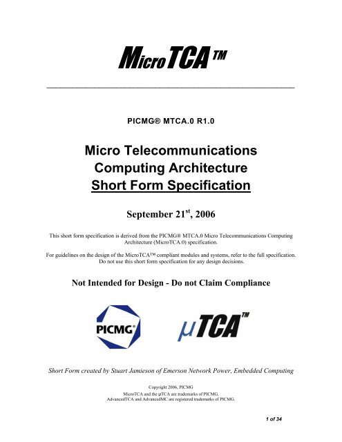
<strong>PICMG</strong>® MTCA.0 R1.0<br />
Micro Telecommunications<br />
Computing Architecture<br />
Short Form Specification<br />
September 21 st , 2006<br />
This short form specification is derived from the <strong>PICMG</strong>® MTCA.0 Micro Telecommunications Computing<br />
Architecture (<strong>MicroTCA</strong>.0) specification.<br />
For guidelines on the design of the <strong>MicroTCA</strong> compliant modules and systems, refer to the full specification.<br />
Do not use this short form specification for any design decisions.<br />
Not Intended for Design - Do not Claim Compliance<br />
Short Form created by Stuart Jamieson of Emerson Network Power, Embedded Computing<br />
Copyright 2006, <strong>PICMG</strong><br />
<strong>MicroTCA</strong> and the µTCA are trademarks of <strong>PICMG</strong>.<br />
AdvancedTCA and AdvancedMC are registered trademarks of <strong>PICMG</strong>.<br />
1 of 34
Not Intended for Design - Do not Claim Compliance<br />
<strong>PICMG</strong>® MTCA.0 Short Form Specification, September 21 st , 2006 2 of 34
Not Intended for Design - Do not Claim Compliance<br />
<strong>PICMG</strong> disclaims all warranties and liability for the use of this document and the information<br />
contained herein and assumes no responsibility for any errors or omissions that may appear in<br />
this document, nor is <strong>PICMG</strong> responsible for any incidental or consequential damages resulting<br />
from the use of any data in this document, nor does <strong>PICMG</strong> assume any responsibility to update<br />
or correct any information in this publication.<br />
<strong>PICMG</strong>® MTCA.0 Short Form Specification, September 21 st , 2006 3 of 34
Overview<br />
Not Intended for Design - Do not Claim Compliance<br />
This short form <strong>PICMG</strong> ® Micro Telecommunications Computing Architecture (<strong>MicroTCA</strong> <strong>TM</strong> ) specification outlines<br />
the requirements for a system that uses <strong>PICMG</strong> Advanced Mezzanine Cards (AdvancedMCs) directly on a Backplane.<br />
The specification defines the general mechanical, electrical, thermal, and management properties of a <strong>MicroTCA</strong><br />
Shelf necessary to support AMC.0-compliant Modules.<br />
This short form specification is for introductory purposes only. For the full details, or for normative requirements,<br />
please refer to the full length <strong>MicroTCA</strong> specification.<br />
Introduction and Objectives<br />
<strong>MicroTCA</strong> has a primary purpose of serving as a platform for telecommunications and enterprise computer network<br />
equipment. Its secondary goal is to function as a platform for other demanding marketplaces, such as Customer<br />
Premises Equipment (CPE).<br />
<strong>MicroTCA</strong> is complementary to the <strong>PICMG</strong>3.0 Advanced Telecommunications Computing Architecture<br />
(AdvancedTCA, or <strong>PICMG</strong>3). Where AdvancedTCA is optimized for very high capacity, high performance<br />
applications, <strong>MicroTCA</strong> is designed to address cost sensitive and physically smaller applications with lower capacity,<br />
performance, and perhaps less stringent availability requirements. <strong>MicroTCA</strong> preserves many of the important philosophies<br />
of AdvancedTCA, including basic interconnect topologies and management structure.<br />
<strong>MicroTCA</strong> is a modular standard. By configuring highly diverse collections of AdvancedMCs in a <strong>MicroTCA</strong> Shelf,<br />
many different application architectures can be easily realized. The common elements defined by <strong>MicroTCA</strong> are<br />
capable of interconnecting these AdvancedMCs in many interesting ways—powering and managing them, all at high<br />
efficiency and low cost.<br />
This <strong>PICMG</strong> <strong>MicroTCA</strong> specification was written with the following design goals in mind:<br />
• Complementary to AdvancedTCA<br />
• Full conformance with the AMC.0 Module definition<br />
• Favorable cost, size, and modularity<br />
• Target low start-up costs<br />
• Scalable Backplane bandwidth<br />
• Modular and serviceable<br />
• Standardized Shelf management implementation compatible with AdvancedTCA<br />
• Support 300 mm nominal equipment depth and 19 in. nominal equipment width<br />
• Cooling: 20–80 W/AdvancedMC<br />
• Support for extended temperatures (–40 to +65 degrees Centigrade)<br />
• Power: 12 V to AdvancedMCs, in conformance with AMC.0<br />
• Life span: at least eight years<br />
• Backplane bandwidth: SerDes @ 1–12+ Gb/s<br />
• Backplane topologies: Star, Dual Star, Mesh<br />
• Scalable system reliability: from .999 to .99999<br />
• Support any/all AdvancedMC-defined form factors<br />
<strong>PICMG</strong>® MTCA.0 Short Form Specification, September 21 st , 2006 4 of 34
Not Intended for Design - Do not Claim Compliance<br />
• Hot Swap/plug-and-play support, in conformance with AMC.0 and consistent with AdvancedTCA<br />
System Elements of <strong>MicroTCA</strong><br />
For the purposes of this specification, a minimum <strong>MicroTCA</strong> system is defined as a collection of interconnected<br />
elements consisting of at least one AdvancedMC, at least one <strong>MicroTCA</strong> Carrier Hub (MCH), and the interconnect,<br />
power, cooling, and mechanical resources needed to support them. As an example, a typical <strong>MicroTCA</strong> system<br />
consists of up to twelve AdvancedMCs, one (and optionally two for redundancy) MCHs, Power Modules (PMs) with<br />
optional redundancy and load sharing, a cooling subsystem (again, optionally redundant), an interconnect (typically<br />
a Backplane), and the mechanical elements comprising a Subrack and Shelf.<br />
Please refer to Figure 1 during the following discussion of <strong>MicroTCA</strong> Shelf elements:<br />
Figure 1 <strong>MicroTCA</strong> block diagram<br />
AdvancedMCs<br />
AdvancedMCs are the primary component of <strong>MicroTCA</strong>. The ability to use any AdvancedMCs that conform to the<br />
AdvancedMC standard without modification in <strong>MicroTCA</strong> is an over arching goal of this standard. They provide the<br />
functional elements needed to implement useful system functions. Examples of AdvancedMCs that could be<br />
installed into a <strong>MicroTCA</strong> Shelf include CPUs, Digital Signal Processing devices, packet processors, storage, and<br />
various sorts of I/O AdvancedMCs (including metallic and optical line units, RF devices, and interfaces to other<br />
boxes). <strong>MicroTCA</strong> offers a significant advantage because the same AdvancedMCs that connect directly to the<br />
<strong>MicroTCA</strong> Backplane can also be equipped on an AdvancedTCA Carrier Board.<br />
<strong>MicroTCA</strong> supports six different mechanical sizes of AdvancedMCs. The largest is the Double Full-Size (formerly<br />
Full-Height, Double-Width) AdvancedMC, which occupies a mechanical volume of 150 x 187.3 x 30.48 mm. This<br />
volume can be subdivided into some number of smaller AdvancedMCs, which permits functions to be better<br />
partitioned onto Modules. The volume of two adjacent Full-Size Modules can be occupied by three Mid-Size or four<br />
Compact AdvancedMCs. Each double AdvancedMC can be replaced by two AdvancedMC of the same Form Factor.<br />
<strong>PICMG</strong>® MTCA.0 Short Form Specification, September 21 st , 2006 5 of 34
Not Intended for Design - Do not Claim Compliance<br />
Figure 2 describes the four AdvancedMC form factors that <strong>MicroTCA</strong> supports, as well as their properties and some<br />
potential applications.<br />
Figure 2 AdvancedMC Module configuration examples<br />
<strong>MicroTCA</strong> Carrier<br />
The <strong>MicroTCA</strong> Carrier concept is the basis for the <strong>MicroTCA</strong> specification. Elements of a <strong>MicroTCA</strong> Shelf act as a<br />
<strong>MicroTCA</strong> Carrier, which emulates the requirements of the Carrier Board defined in AMC.0 to properly host<br />
AdvancedMC Modules. Carrier functional requirements include power delivery, interconnects, and Intelligent<br />
Peripheral Management Interface (IPMI) management, among others as defined in the AMC.0 base specification.<br />
These Carrier functions are implemented on AdvancedTCA Carrier Boards that accept up to eight AdvancedMCs. The<br />
term “<strong>MicroTCA</strong> Carrier” used in <strong>MicroTCA</strong> refers to Carrier functions needed to provide an infrastructure that<br />
supports nominally twelve AdvancedMCs. The elements inside the dotted line in Figure 1 represent the <strong>MicroTCA</strong><br />
Carrier functions.<br />
A <strong>MicroTCA</strong> Carrier Hub (MCH) combines the control and management infrastructure and the interconnect fabric<br />
resources needed to support up to twelve AdvancedMCs into a single Module, which is the same size as an<br />
AdvancedMC. MCHs are the infrastructure elements that are shared by all AdvancedMCs. Since MCHs represent a<br />
single point of failure in a <strong>MicroTCA</strong> solution (where any fault could bring down the entire system), it is possible to<br />
include a pair of MCHs to make the solution suitable for High Availability (HA) applications. Figure 3 shows a<br />
block diagram of an MCH.<br />
<strong>PICMG</strong>® MTCA.0 Short Form Specification, September 21 st , 2006 6 of 34
Not Intended for Design - Do not Claim Compliance<br />
Figure 3 <strong>MicroTCA</strong> Carrier Hub block diagram (12 AdvancedMCs/48 Lanes)<br />
Backplane and Connectors<br />
<strong>MicroTCA</strong> requires a Backplane into which the AdvancedMCs and other elements are plugged. High performance<br />
connectors of several types are specified by <strong>MicroTCA</strong>. <strong>MicroTCA</strong> Carrier elements typically occupy one or more<br />
Slots on the Backplane. AdvancedMC Backplane Connectors at each AdvancedMC position bring the signals from the<br />
AdvancedMC’s card edge connector into the Backplane.<br />
Another connector type, called the <strong>MicroTCA</strong> Carrier Hub Connector, is used to connect an MCH to the backplane to<br />
carry the signals to multiple AdvancedMCs. These connectors are optimized to carry high speed serial signals<br />
(supporting bit rates over 10 Gb/s). Power Module Input Connectors are used to bring the input power to the Power<br />
Modules. Power Module Output Connectors carry high current power supply connections and various control and<br />
management signals from the Power Modules to the Backplane.<br />
Mechanical infrastructure/Subrack<br />
A mechanical support structure is required to hold the AdvancedMCs, <strong>MicroTCA</strong> Carrier elements and Backplane<br />
in correct alignment and secure it to the supporting chassis or Frame. This structure, including mounting holes, Card<br />
Guides, EMC/ESD control structures, and the means to direct the cooling airflow, is called the Subrack. Various<br />
additional mechanical elements, including a means to mount the cooling and power elements, cable guides, and<br />
brackets, are added to the Subrack to form the entire mechanical infrastructure (Shelf, Cube, or Pico) of a <strong>MicroTCA</strong><br />
Shelf.<br />
Cooling and thermal subsystem<br />
<strong>MicroTCA</strong> Shelves can have high power density. A cooling infrastructure is necessary to remove this heat from the<br />
electronics. Typically, this will consist of fans or blowers, filters, and air plenums which direct a large flow of forced<br />
air through the air paths between the AdvancedMCs and <strong>MicroTCA</strong> Carrier elements. <strong>MicroTCA</strong> Shelves may use<br />
different cooling approaches, such as conductive cooling or natural convection.<br />
<strong>PICMG</strong>® MTCA.0 Short Form Specification, September 21 st , 2006 7 of 34
Not Intended for Design - Do not Claim Compliance<br />
Control and management infrastructure<br />
The first element of an MCH is the <strong>MicroTCA</strong> Carrier Management Controller (MCMC) with its Carrier Manager<br />
function as the central authority in a <strong>MicroTCA</strong> Carrier to monitor and control the constituent AdvancedMCs. The<br />
Carrier Manager function makes use of IPMB-L Links to each AdvancedMC, as well as presence detect, enable, and<br />
Geographic Address signals. IPMB-L and IPMB-0 are located on the MCH(s), while presence detect and enable<br />
control are implemented in the Power Modules, under Carrier Manager control.<br />
The <strong>MicroTCA</strong> Shelf, consisting of one or more <strong>MicroTCA</strong> Carriers, is managed by the Shelf Manager. The<br />
<strong>MicroTCA</strong> Shelf Manager also monitors events and controls the Cooling Units.<br />
The control and management subsystem of the <strong>MicroTCA</strong> Carrier also includes the common overhead functions of<br />
clock generation and distribution. Several clock signals are distributed to each AdvancedMC position in order to<br />
provide network grade synchronization.<br />
Interconnect fabric infrastructure<br />
An interconnect fabric provides the main connectivity among the AdvancedMCs in a <strong>MicroTCA</strong> Shelf. This<br />
interconnect consists of a central switch and a number of high speed serial Lanes to each AdvancedMC position.<br />
Lanes on <strong>MicroTCA</strong> are differential high speed Serializer / Deserializer interconnects (SerDes), with bandwidth<br />
capability of at least 3.125 Gb/s in each direction. Although some <strong>MicroTCA</strong> implementations using inexpensive<br />
connectors and backplanes will run these Lanes at slower rates such as 1 Gb/s, many <strong>MicroTCA</strong> Shelves will permit<br />
these bit rates to increase to beyond 10 Gb/s per Lane.<br />
The interconnect protocol used in <strong>MicroTCA</strong> depends upon the specific format expected by the AdvancedMCs and<br />
implemented on the MCHs fabric. All AdvancedMC subsidiary specification formats are supported in <strong>MicroTCA</strong>,<br />
including PCI Express/Advanced Switching (AMC. 1), Ethernet (AMC.2), Storage Interfaces (AMC.3), and<br />
RapidIO (AMC.4). Future subsidiary specifications of AdvancedMCs, as well as proprietary Backplane protocols,<br />
are also possible.<br />
The fabric component of an MCH is the hub of a star network. Two MCHs are required to implement a dual-star<br />
network. In some <strong>MicroTCA</strong> Shelves, there are supplementary paths directly from each AdvancedMC position to<br />
other AdvancedMC positions, permitting the construction of supplemental mesh interconnects and special I/O<br />
structures, in addition to the dual star supported by the MCH fabrics.<br />
Power infrastructure<br />
One important function of the <strong>MicroTCA</strong> Carrier is to supply and control the power to the AdvancedMCs. The<br />
AdvancedMC standard specifies a 12 V main Payload Power feed to each AdvancedMC. The <strong>MicroTCA</strong> Power<br />
Module(s) take the input supply and convert it to 12 V to provide radial Payload Power to each AdvancedMC. 3.3 V<br />
Management Power for AdvancedMCs is also supplied by the Power Subsystem. The power control logic on the<br />
Power Module performs sequencing, protection, and isolation functions. The Power Subsystem is controlled via the<br />
Carrier Manager which performs power budgeting to ensure adequate power is available prior to enabling Power<br />
Channels.<br />
The Power Subsystem consists of one or more Power Modules. Each Power Module is responsible for converting the<br />
input supply that arrives at an Input Power Connector on its Face Plate (either AC or DC) to the individual branches of<br />
12 V Payload Power and 3.3 V Management Power needed to run the AdvancedMCs, MCHs, and CUs. If extra<br />
capacity or redundancy is required, up to four Power Modules can be managed in a <strong>MicroTCA</strong> Shelf.<br />
Power Modules also include the supervisory functions necessary to manage the Power Subsystem. They have<br />
circuitry to detect the presence of AdvancedMCs, MCHs, and CUs, and to energize individual power branches.<br />
Power Modules also monitor the power quality of each branch and protect against overload. If a Redundant Power<br />
Module is configured, it will automatically take over the Power Channel responsibilities of a failed Primary Power<br />
Module.<br />
<strong>PICMG</strong>® MTCA.0 Short Form Specification, September 21 st , 2006 8 of 34
Not Intended for Design - Do not Claim Compliance<br />
Test Infrastructure<br />
An optional JTAG Switch Module (JSM) supports serial scan testing of complete <strong>MicroTCA</strong> Shelves, as well as<br />
their individual elements. This testing is most often carried out during manufacturing tests in a factory setting, but<br />
<strong>MicroTCA</strong> can also supports the use of these JTAG test capabilities in active systems in the field. JSM functions may<br />
be located in special slots on the backplane, or integrated into other Modules.<br />
Theory of operation<br />
<strong>MicroTCA</strong> works by providing the necessary infrastructure and interconnections to permit the AdvancedMC<br />
elements in a system to perform their intended functions. The MCH provides the management, clock, and fabric hub<br />
signals required by the AdvancedMC specification to each AdvancedMC position over the Backplane. Please refer<br />
back to Figure 1 during the following discussion of <strong>MicroTCA</strong> Shelf operation.<br />
The primary function of this <strong>MicroTCA</strong> system is to support the various types of AdvancedMCs that perform the<br />
system’s processing, storage, and I/O functions. The twelve AdvancedMC positions shown in Figure 1 can be<br />
populated with a diverse mix of AdvancedMC types. Conversely, it is possible to configure a <strong>MicroTCA</strong> system with<br />
only a single type of AdvancedMC. AdvancedMCs can include functionality that employs CPUs for control and<br />
feature processing, network processing units for packet processing and I/O, DSP AdvancedMCs for signal processing,<br />
storage AdvancedMCs, including built-in disk or flash storage, or interfaces to external storage arrays, and various<br />
I/O AdvancedMCs, such as subscriber lines, Ethernet, or optical networking.<br />
A set of common functions is needed to manage the AdvancedMCs, as shown in Figure 3. These functions are<br />
included in the MCH Module. They include a primary interconnect fabric to interconnect the high speed serial<br />
interfaces on AdvancedMCs, <strong>MicroTCA</strong> Carrier Management Controller (MCMC) and Carrier Manager functions to<br />
configure and control the elements, synchronization clocks, and JTAG test circuits. MCHs are optionally duplicated,<br />
permitting the creation of highly reliable systems.<br />
The switch fabric may support any of several protocols, as defined by the AdvancedMC subsidiary specifications<br />
that govern the complement of AdvancedMCs in a given <strong>MicroTCA</strong> Shelf. A PCI Express/Advanced Switching<br />
fabric supports AMC. 1, an Ethernet fabric supports AMC.2, a storage fabric switch supports AMC.3, and a serial<br />
RapidIO switch supports AMC.4. Other protocols for the switch fabric are possible.<br />
In addition to the MCH, a power infrastructure is required for a <strong>MicroTCA</strong> Carrier. Power is delivered to a <strong>MicroTCA</strong><br />
Shelf through either connections to AC mains voltage or to the +24, -48, or -60 V DC supplies typical of<br />
telecommunication installations. The Power Module produces the +12 V DC Payload Power required to operate the<br />
AdvancedMCs from the input voltage. The power control block splits, switches, distributes, and protects this +12 V<br />
source for the AdvancedMCs. The Power Module also produces, controls, and monitors multiple branches of +3.3 V<br />
Management Power for radial distribution to the AdvancedMCs, MCHs, PMs, and Cooling Units.<br />
Hot Swap support is another important function of the <strong>MicroTCA</strong> Carrier. Individual AdvancedMCs must be<br />
installed and removed from a <strong>MicroTCA</strong> Shelf without disrupting the operation of the other AdvancedMCs. Hot<br />
Swap functions on the PMs and Carrier Manager ensure that no damaging power transients occur as AdvancedMCs<br />
are inserted and withdrawn, and no disruptions hamper the operations of other AdvancedMCs that may share the same<br />
power infrastructure.<br />
A set of Cooling Units ensures that enough air is forced through the AdvancedMC, PM, and MCH air pathways to keep<br />
their temperature within a safe thermal envelope. These Cooling Units typically consist of several individual fans or<br />
blowers working in parallel to move an appropriate amount of air at the required pressure. Control systems in the Shelf<br />
Manager and Cooling Unit can dynamically adjust the fan speeds in order to provide enough cooling for the given<br />
environmental condition, minimizing component wear and acoustic noise.<br />
Fault tolerance and several redundancy options are supported in <strong>MicroTCA</strong>. Simple, inexpensive systems with less<br />
stringent availability requirements are often implemented as simplex Shelves with single MCHs and PMs. As more<br />
reliability is required, the common elements of a <strong>MicroTCA</strong> Shelf can be duplicated optionally, including a pair of<br />
<strong>PICMG</strong>® MTCA.0 Short Form Specification, September 21 st , 2006 9 of 34
Not Intended for Design - Do not Claim Compliance<br />
MCHs, duplex or N+1 spared PMs, and redundant CUs. Availability levels up to 99.999% are supported in fully<br />
redundant <strong>MicroTCA</strong> Shelves.<br />
Glossary<br />
The following glossary contains definitions of terms and acronyms that appear in this document:<br />
Table 1 Glossary<br />
Term or acronym Description<br />
Backplane An interconnecting device with connectors, allowing Modules to plug into it<br />
Board<br />
An electronic assembly usually consisting of components mounted on a printed circuit<br />
Card Guide A mechanical component that provides AdvancedMC guidance in a Slot<br />
Component Side 1 The side of the AdvancedMC which supports the greater Component Envelope Height<br />
Component Side 2<br />
The side of the AdvancedMC which supports the lower Component Envelope Height.<br />
This side can be used for the solder connections of the components on Component<br />
Side 1 and for low-height electronic components.<br />
Contact List Defines the use of each contact. Directed signals appear in the lists differently, as<br />
applicable to the respective viewpoint of the Module and the <strong>MicroTCA</strong> Backplane.<br />
Cooling Unit (CU) A subassembly including fans or blowers to move air to cool a <strong>MicroTCA</strong> Shelf and<br />
related support electronics<br />
CPE Customer Premise(s) Equipment<br />
Cube<br />
Double-Width Slot<br />
Double-Width<br />
Module<br />
Electronic Keying<br />
or E-Keying<br />
Fabric Interface<br />
Frame<br />
FRU<br />
Half-Height<br />
Module<br />
A <strong>MicroTCA</strong> packaging option where AdvancedMCs, MCHs, PMs, cooling, and<br />
mechanical elements are all packaged in a small, roughly cubic enclosure that is<br />
approximately 200 mm or 8 in. on a side<br />
Mounting location on a <strong>MicroTCA</strong> Shelf for a Full-Height or Half-Height Double-Width<br />
Module. Double-Width Slots may be created by removing a Strut and Card Guide<br />
between two Single-Width Slots.<br />
A Module that is roughly twice the width of a Single-Width AdvancedMC Module.<br />
Double-Width AdvancedMCs measure approximately 150 mm wide.<br />
Abbreviation for Electronic Keying. Electronic Keying defines the process in which a<br />
<strong>MicroTCA</strong> Carrier determines if the Control and Fabric interfaces on a Module are<br />
compatible with the <strong>MicroTCA</strong> Carrier interconnects and the other Modules they reach.<br />
The set of MCH Fabric Channel interfaces that provides up to seven Fabric Channels<br />
to the Advanced MCs<br />
An enclosure used for mounting one or more <strong>MicroTCA</strong> Shelves<br />
Field Replaceable Unit, any entity that can be replaced by a user in the field<br />
The component height on Component Side 1 of Half-Height Modules is optimized to<br />
allow for two stacked Modules to equally split the maximum height (AdvancedTCA<br />
pitch) available. The term Half-Height should not be taken literally as being half of a<br />
Full-Height Module. Face Plate height is 13.88 mm.<br />
Intelligent FRU A FRU containing a management controller. Intelligent FRUs include the<br />
AdvancedMCs, MCHs, CUs, PMs, and OEM Modules, etc.<br />
<strong>PICMG</strong>® MTCA.0 Short Form Specification, September 21 st , 2006 10 of 34
Not Intended for Design - Do not Claim Compliance<br />
Table 1 Glossary (continued)<br />
Term or acronym Description<br />
JTAG<br />
Management<br />
Power (MP)<br />
Shelf<br />
Shelf Manager<br />
Single-Width<br />
Module<br />
Slot<br />
Subrack<br />
Zone 2<br />
Zone 3<br />
Formally, Joint Test Action Group, an organization that proposed adoption of a<br />
specification for a test access port and boundary-scan architecture. Informally, but<br />
commonly, the standard, namely IEEE Std 1149.1, that arose from the efforts of the<br />
Joint Test Action Group.<br />
The 3.3 V power for a Module ' s management function, individually provided to each<br />
Slot by the <strong>MicroTCA</strong> Shelf<br />
An electronic assembly consisting of the Subrack, Backplane, Modules, cooling<br />
devices, power subsystems, etc. for one or more <strong>MicroTCA</strong> Carriers. Also historically<br />
known as a chassis. Shelves are usually mounted in Frames.<br />
The entity responsible for managing the cooling in a <strong>MicroTCA</strong> Shelf. It also routes<br />
messages between the System Manager Interface and the Shelf-Carrier Manager<br />
Interface, provides interfaces to system repositories, and responds to event<br />
messages.<br />
AdvancedMC Module with a width around 74 mm which fits in a Single-Width<br />
AdvancedMC Slot<br />
The union of a Connector and a Card Guide that defines the position of one<br />
AdvancedMC, MCH, Power Module, OEM Module or CU. Slots are similar in concept<br />
to the Bays used in the AMC.0 specification. A <strong>MicroTCA</strong> Subrack typically contains<br />
multiple Slots.<br />
A mechanical assembly that provides the interface to Modules, including<br />
AdvancedMCs, and consists of the Card Guides, ESD discharge, alignment/keying,<br />
Handle interface, Face Plate mounting hardware, EMC Gasketing, and Backplane<br />
interface<br />
A region used for I/O expansion typically to the left of an AdvancedMC Connector<br />
within a Slot (standard vertical orientation, viewed from the front)<br />
A region used for I/O expansion typically above an AdvancedMC Connector within a<br />
Slot (standard vertical orientation, viewed from the front)<br />
<strong>PICMG</strong>® MTCA.0 Short Form Specification, September 21 st , 2006 11 of 34
Mechanical<br />
Not Intended for Design - Do not Claim Compliance<br />
The mechanical <strong>MicroTCA</strong> structure holds the AdvancedMC Modules, MCH Modules, Power Modules, JTAG<br />
Switch Modules, FRU ROMs, and the Backplane into the correct alignment. The architecture defines a rackmountable<br />
Shelf, which may be divided by Cubes, or free-standing Cubes, or Pico subassemblies to be populated<br />
with AdvancedMC Modules.<br />
Shelf<br />
There are basically two types of Shelves:<br />
• The 19 in. Shelf, as defined in IEC 60297<br />
• The Metric Shelf, as defined in IEC 60917 and ETS 300 119-4<br />
Figure 4 Example of a Shelf<br />
Shelf dimensions<br />
Figure 5 Shelf dimensions—top view<br />
<strong>PICMG</strong>® MTCA.0 Short Form Specification, September 21 st , 2006 12 of 34
Not Intended for Design - Do not Claim Compliance<br />
Table 2 Shelf dimension<br />
IEC 60297<br />
19 in.<br />
IEC 60917<br />
Metric<br />
(ETSI)<br />
IEC 60917<br />
Metric<br />
(ETSI)<br />
W6 Shelf<br />
Width<br />
W4 Shelf<br />
Body<br />
Width<br />
Frame<br />
Width<br />
Aperture<br />
W5 Frame<br />
Mounting<br />
Points<br />
482.60 = 450 465.10<br />
535.00 = 500 515.00<br />
482.60 = 450 465.10<br />
Optional Subrack attachment plane<br />
The optional attachment plane provides for the following additional features:<br />
Height<br />
U= 44.45mm<br />
n x U<br />
SU= 25.0mm<br />
n x SU<br />
SU= 25.0mm<br />
n x SU<br />
• The attachment of filler panels (low cost)<br />
• The attachment of filler/airflow management devices (low cost)<br />
• The attachment of front access conversion devices (field-replaceable)<br />
• The attachment of PMs (weight/size) See Section 2.8, “Power entry/Power Module”.<br />
• The attachment of cable management devices See Section 2.7, “Cable management”.<br />
• The attachment of additional AdvancedMC Module locking devices<br />
<strong>PICMG</strong>® MTCA.0 Short Form Specification, September 21 st , 2006 13 of 34
Not Intended for Design - Do not Claim Compliance<br />
<strong>MicroTCA</strong> enclosure types<br />
The standard <strong>MicroTCA</strong> elements described in this document can be assembled into many different types of systems<br />
that conform to this specification. Although the variability of these systems is large, it is believed that there will be a<br />
few popular implementation types. This section describes a few of these types in order to provide more concrete<br />
illustrations of how to assemble the standard elements into actual systems. It should be understood that other<br />
arrangements of the standard elements are possible and can still represent full compliance with the <strong>MicroTCA</strong><br />
specification.<br />
Figure 6 illustrates six different packaging possibilities for <strong>MicroTCA</strong>. Different complements of AdvancedMCs will<br />
fit, depending upon AdvancedMC size, MCH capacity, Shelf width, and Shelf height. This section (and the rest of<br />
this specification) emphasizes vertical placement of boards; however horizontal board orientation is also permitted,<br />
and has mechanical and thermal implications. <strong>MicroTCA</strong> also permits variations in airflow paths, location of cooling<br />
units, and cable management capabilities.<br />
Figure 6 <strong>MicroTCA</strong> packaging illustration<br />
<strong>PICMG</strong>® MTCA.0 Short Form Specification, September 21 st , 2006 14 of 34
Not Intended for Design - Do not Claim Compliance<br />
Typical arrangement examples<br />
The following figures show examples of typical mechanical arrangements for <strong>MicroTCA</strong> systems:<br />
Figure 7 Overview example<br />
Figure 8 Shelf examples for Single-Width (75 mm) and Double-Width (150 mm)<br />
AdvancedMC Modules<br />
<strong>PICMG</strong>® MTCA.0 Short Form Specification, September 21 st , 2006 15 of 34
Not Intended for Design - Do not Claim Compliance<br />
Figure 9 Shelf detail example<br />
Figure 10 Multiple Shelves in a Frame example<br />
<strong>PICMG</strong>® MTCA.0 Short Form Specification, September 21 st , 2006 16 of 34
Not Intended for Design - Do not Claim Compliance<br />
Figure 11 Single Cube on a mounting plate example<br />
Figure 12 Multiple Carriers in a Shelf example<br />
Figure 13 Pico on a panel example<br />
<strong>PICMG</strong>® MTCA.0 Short Form Specification, September 21 st , 2006 17 of 34
Not Intended for Design - Do not Claim Compliance<br />
Figure 14 Pico on a motherboard host example<br />
Other implementation options<br />
It is important to realize that <strong>MicroTCA</strong> Shelves can be constructed using alternative physical arrangements not<br />
shown here. <strong>MicroTCA</strong> Shelves are not limited to cabinet-mounted applications. The compact size of AdvancedMCs<br />
allows <strong>MicroTCA</strong> enclosures to fit into a variety of space-constrained applications, where only a few AdvancedMCs<br />
are needed to complete a system.<br />
<strong>MicroTCA</strong> Shelves also can be large capacity systems, perhaps with hundreds of AdvancedMCs making up the<br />
complete system. These can combine many communities of AdvancedMCs in multiple Tiers and back-to-back<br />
packaging to achieve a very high system density.<br />
In the future special <strong>MicroTCA</strong> Shelves may be developed for applications where extended temperature, ruggedness,<br />
or other environmental factors dictate enclosure design. Additionally Industrial, medical, and military applications of<br />
<strong>MicroTCA</strong> may require special packaging options. Extensions to this <strong>MicroTCA</strong> specification will be required to<br />
accommodate these demanding environmental requirements.<br />
<strong>PICMG</strong>® MTCA.0 Short Form Specification, September 21 st , 2006 18 of 34
Not Intended for Design - Do not Claim Compliance<br />
<strong>MicroTCA</strong> Carrier Hub<br />
The <strong>MicroTCA</strong> Carrier Hub provides the fabric, clock and management for the <strong>MicroTCA</strong> Carrier. This<br />
functionality can be provided by a modular multi-board form-factor assembly or as functionality implemented on the<br />
backplane/motherboard (as in the Pico configuration). The level of functionality provided by the MCH can also<br />
flexible and as such the specification provides the scope to have multiple PCBs, as well as multiple connectors to the<br />
backplane (see Figure 15).<br />
Figure 15 MCH module types<br />
Auxiliary Connector (Zone 2 and Zone 3) keying<br />
A simple mechanical Auxiliary Connector keying method is used to simplify interoperability between<br />
AdvancedMCs and <strong>MicroTCA</strong> Backplanes that use the Backplane Connector Zones 2 and 3 areas. This framework<br />
restricts how AdvancedMCs and <strong>MicroTCA</strong> Backplanes interact, so that in the future designers can take advantage<br />
of Zones 2 and 3 in such a way as to allow forward compatibility and additionally prevent any mechanical or<br />
electrical damage to any of these components.<br />
Power entry/Power Module<br />
The power entry into a <strong>MicroTCA</strong> Shelf, Cube, or Pico may be accomplished via:<br />
• DC or AC power source<br />
• Separate power source<br />
• Integrated power source<br />
• Power Module which fits into a specific Power Module slot in a <strong>MicroTCA</strong> Subrack.<br />
Power Modules occupy an integral number of Half-Height Slots. The weight of a Power Module must not exceed<br />
1000 g. Power Modules should be located in the outermost Slots of a Shelf.<br />
<strong>PICMG</strong>® MTCA.0 Short Form Specification, September 21 st , 2006 19 of 34
Not Intended for Design - Do not Claim Compliance<br />
Figure 16 Power Module Example<br />
Cooling Units (CUs)<br />
CUs may be of different design or configuration.<br />
• CUs can be designed as an integral part of a <strong>MicroTCA</strong> Shelf, Cube or Pico enclosure or separate unit.<br />
• CUs can be of redundant or non-redundant nature.<br />
• CUs can be designed as a FRU or component of the total <strong>MicroTCA</strong> supporting installation.<br />
• A CU can contain single or multiple FRUs.<br />
<strong>PICMG</strong>® MTCA.0 Short Form Specification, September 21 st , 2006 20 of 34
Not Intended for Design - Do not Claim Compliance<br />
Hardware Platform Management<br />
<strong>MicroTCA</strong> provides for extensive hardware platform management capabilities, which may be used by an overall<br />
System Manager. The management capabilities defined in this specification facilitate:<br />
• Low-level hardware management services, based on the Intelligent Platform Management<br />
Interface (IPMI)<br />
• High-speed management services, based on an Internet Protocol (IP) suite<br />
<strong>MicroTCA</strong> hardware platform management includes Module management, <strong>MicroTCA</strong> Carrier management, and<br />
Shelf management. In this section, the term Module is used to refer to a Module supported in <strong>MicroTCA</strong>, including<br />
the MCH, AdvancedMC, PM, CU and OEM Modules.<br />
The <strong>MicroTCA</strong> specification leverages the management architecture and requirements defined in the AMC.0<br />
specification to preserve AdvancedMC compatibility in a <strong>MicroTCA</strong> Shelf. The specification covers <strong>MicroTCA</strong><br />
management other than AdvancedMC management, which is defined in the AMC.0 specification. Therefore, readers<br />
of this short form specification will find being conversant with the platform management aspects described in the IPMI,<br />
AdvancedTCA, and AMC.0 specifications helpful.<br />
<strong>MicroTCA</strong> hardware platform management does not cover the implementation of the <strong>MicroTCA</strong> Shelf for different<br />
form factors. Instead, it specifies the following minimum requirements:<br />
• AdvancedMC management, such that AMC.0 Base specification-compliant AdvancedMCs can<br />
interoperate with AdvancedTCA Carrier Boards or <strong>MicroTCA</strong> Carriers.<br />
• <strong>MicroTCA</strong> Carrier management, which is conceptually similar to the management of an AdvancedTCA<br />
Carrier Board.<br />
• Shelf management, which can involve one or more <strong>MicroTCA</strong> Carriers comprising a <strong>MicroTCA</strong><br />
Shelf.<br />
<strong>MicroTCA</strong> management architecture<br />
Figure 17 shows the logical elements of a sample <strong>MicroTCA</strong> Shelf, with primary emphasis on management.<br />
<strong>PICMG</strong>® MTCA.0 Short Form Specification, September 21 st , 2006 21 of 34
Not Intended for Design - Do not Claim Compliance<br />
Figure 17 Management aspects of an example <strong>MicroTCA</strong> Shelf<br />
Device 2<br />
MCMC<br />
84 Lane Fabric Switch 84 Lane Fabric Switch<br />
Power Module<br />
(up to 4)<br />
Shelf<br />
Manager<br />
Enhanced Module Management Controller(EMMC)<br />
<strong>MicroTCA</strong> Carrier Management Controller (MCMC)<br />
Module Management Controller (MMC)<br />
Advanced Mezzanine Card (AMC)<br />
<strong>MicroTCA</strong> Carrier Hub (MCH)<br />
Other Field Replaceable Unit (FRU)<br />
Other non Field Replaceable Unit<br />
Logical Manager Function<br />
IPMB-L [1:12]<br />
PS1# [1:16] _<br />
ENABLE [1:16]<br />
The System Manager is the highest-level management entity in <strong>MicroTCA</strong>. It is responsible for managing one or<br />
more <strong>MicroTCA</strong> Shelves and possibly other Shelf types. It is a logical entity and beyond the scope of the <strong>MicroTCA</strong><br />
specification. Figure 17 shows a System Manager external to the Shelf. In some systems (such as single Shelf<br />
systems), the System Manager can be integrated within the Shelf.<br />
The <strong>MicroTCA</strong> Shelf Manager manages up to sixteen <strong>MicroTCA</strong> Carriers that comprise a <strong>MicroTCA</strong> Shelf. Each<br />
Carrier Manager interfaces to the Shelf Manager using a logical Shelf-Carrier Manager Interface, which can be an<br />
IP-based interface. The <strong>MicroTCA</strong> specification preserves the management hierarchy of an AdvancedTCA system<br />
through the <strong>MicroTCA</strong> Carrier model.<br />
The Shelf Manager is a mandatory logical management function and can be implemented on any FRU. In a<br />
<strong>MicroTCA</strong> Shelf, the Shelf Manager functions as the aggregation point for hardware management information from<br />
one or more <strong>MicroTCA</strong> Carriers. The Shelf Manager watches over managed entities such as AdvancedMCs, MCHs,<br />
PMs, CUs, and OEM Modules. It reports anomalous conditions to the System Manager and takes corrective actions<br />
where appropriate. The Shelf Manager can also provide the collective hardware health status of the <strong>MicroTCA</strong><br />
Carriers that comprise the <strong>MicroTCA</strong> Shelf and can communicate with the telco alarms for visual/audible indications<br />
of the collective health status of the <strong>MicroTCA</strong> Shelf that it monitors.<br />
<strong>PICMG</strong>® MTCA.0 Short Form Specification, September 21 st , 2006 22 of 34<br />
AMC 12
Not Intended for Design - Do not Claim Compliance<br />
The <strong>MicroTCA</strong> specification recommends that redundant Shelf Manager instances be provided. The specification<br />
does not specify the mechanisms by which an active Shelf Manager communicates with its backup(s). The selection<br />
of the backup, coherency of redundant information, and the fail-over process are all beyond the scope of the<br />
<strong>MicroTCA</strong> specification.<br />
<strong>MicroTCA</strong> Carrier model<br />
The <strong>MicroTCA</strong> Carrier leverages the AdvancedMC Carrier Board management architecture, which is defined in the<br />
AMC.0 specification. A <strong>MicroTCA</strong> Shelf consists of at least one <strong>MicroTCA</strong> Carrier. Up to sixteen <strong>MicroTCA</strong><br />
Carriers can be grouped together to form a single <strong>MicroTCA</strong> Shelf.<br />
<strong>MicroTCA</strong> Carrier management functions are fulfilled by the Carrier Manager, a logical function that manages each<br />
<strong>MicroTCA</strong> Carrier, possibly with redundant instances. This document uses Carrier Manager to refer to the <strong>MicroTCA</strong><br />
Carrier Manager.<br />
The Carrier Manager function resides with a <strong>MicroTCA</strong> Carrier Management Controller (MCMC), a physical<br />
management controller similar to an AdvancedTCA Carrier IPM Controller. The Carrier Manager and MCMC<br />
reside with Fabric switches and clock distribution on the <strong>MicroTCA</strong> Carrier Hub (MCH). A <strong>MicroTCA</strong> Carrier can be<br />
implemented with either single or redundant MCHs.<br />
Additional <strong>MicroTCA</strong> Carrier architectural elements include Module Management Controllers (MMCs) present in<br />
AdvancedMCs, Enhanced Module Management Controllers (EMMCs) present in PMs, CUs and OEM Modules,<br />
Carrier FRU Information devices, management hardware interfaces, and a set of management commands.<br />
The Carrier Manager, representing the entire <strong>MicroTCA</strong> Carrier, exists on only one MCH at a time, even if a<br />
redundant MCH is available. The Carrier Manager is at address 20h on IPMB-0 and IPMB-L. The MCMC only<br />
represents its MCH local sensors and is at address 1 0h for MCMC 1 and 12h for MCMC 2 on IPMB-0.<br />
The MCMC is a variant of an AdvancedTCA-defined IPM Controller and communicates with the Carrier Manager,<br />
a logical management function that provides management interfaces to managed entities within a <strong>MicroTCA</strong> Carrier.<br />
The Carrier Manager manages the AdvancedMCs, MCHs, PMs, CUs and OEM Modules, and represents these<br />
entities in a <strong>MicroTCA</strong> Carrier to the Shelf Manager.<br />
Key differences from <strong>PICMG</strong> 3.0 and AMC.0<br />
specifications<br />
While the <strong>MicroTCA</strong> specification attempts to closely follow the management capabilities defined in the <strong>PICMG</strong><br />
3.0 AdvancedTCA specification, the unique nature of <strong>MicroTCA</strong> concepts, scalable reliability, and cost<br />
requirements necessitate certain differences in capabilities.<br />
The <strong>MicroTCA</strong> Shelf Manager functions are not the same as the functions of the AdvancedTCA Shelf Manager.<br />
Many of the functions performed by the Shelf Manager in AdvancedTCA are performed by the Carrier Manager in<br />
<strong>MicroTCA</strong>. The following paragraphs describe some areas where specific AdvancedTCA-defined features may be<br />
impacted or extended.<br />
Certain FRUs need to be powered-up by the Carrier Manager before the Shelf Manager is operational in the<br />
<strong>MicroTCA</strong> Shelf, for example, when the Shelf Manager is running on an AdvancedMC. For such FRUs, activation<br />
is managed by the Carrier Manager, based on the contents of the <strong>MicroTCA</strong> Carrier Activation and Power<br />
Management record in the Carrier FRU Information.<br />
A newly connected Shelf Manager must discover the state of the already activated FRUs. This is similar to the<br />
behavior of an AdvancedTCA Shelf Manager when starting in a running AdvancedTCA Shelf.<br />
There is no Shelf-level power budget function in <strong>MicroTCA</strong>. The Shelf Manager does not participate in <strong>MicroTCA</strong><br />
Carrier power budgeting.<br />
<strong>PICMG</strong>® MTCA.0 Short Form Specification, September 21 st , 2006 23 of 34
Not Intended for Design - Do not Claim Compliance<br />
The Shelf-Carrier Manager Interface between a remote Shelf Manager and a Carrier Manager is an IP-capable<br />
interface. This is different from AdvancedTCA, which uses IPMB-0 as the primary in-Shelf management<br />
communication interface. An RMCP session is created by the Carrier Manager to the remote Shelf Manager prior to<br />
any management commands being issued to the Carrier Manager or events being sent to the Shelf Manager. The<br />
implementation is free to choose the level of security for the RMCP session within the constraints of what is<br />
specified in the IPMI specification.<br />
When a Shelf Manager is located with a Carrier Manager, the Shelf-Carrier Manager Interface is implementationdefined.<br />
The Carrier Manager and the local Shelf Manager establish the Shelf-Carrier Manager Interface during<br />
Carrier Manager startup.<br />
The Shelf Manager receives platform event messages from Carrier Managers over the Shelf-Carrier Manager<br />
Interface.<br />
The Shelf Manager does not provide E-Keying for the <strong>MicroTCA</strong> Carrier or for implementation-defined inter-<br />
<strong>MicroTCA</strong> Carrier connections. The Carrier Manager performs the E - Keying functions within a <strong>MicroTCA</strong> Carrier.<br />
A <strong>MicroTCA</strong> FRU can be activated by the Carrier Manager without Shelf Manager involvement. When activating a<br />
FRU, the Carrier Manager commands a PM to enable Payload Power only if the <strong>MicroTCA</strong> Carrier Power<br />
Subsystem can meet the FRU’s power requirements.<br />
The <strong>MicroTCA</strong> Shelf Manager does not participate in power budgeting or E-Keying. The Carrier Manager handles<br />
those responsibilities.<br />
The Carrier Manager performs power budgeting in the M3 state for a given FRU, in contrast to AMC.0 where the<br />
Carrier-level power budgeting is done in the M1 state.<br />
After the Carrier Manager has established the Shelf-Carrier Manager Interface with the Shelf Manager, the Shelf<br />
Manager discovers the already activated <strong>MicroTCA</strong> FRUs and synchronizes its internally tracked FRU states with<br />
the <strong>MicroTCA</strong> Carrier FRU states.<br />
The <strong>MicroTCA</strong> Shelf FRU Information is specified as a logical entity and can be located in the Carrier FRU<br />
Information device. In implementations where the Shelf FRU Information is located with the Carrier FRU<br />
Information, the Shelf Manager reads the Shelf FRU Information from the Carrier Manager using FRU Device IDs 1<br />
and 2. In a Shelf with multiple <strong>MicroTCA</strong> Carriers, the Shelf FRU Information is located and validated as part of the<br />
Shelf Manager election process. Other Shelf FRU Information location implementations are not precluded by this<br />
specification.<br />
.<br />
<strong>PICMG</strong>® MTCA.0 Short Form Specification, September 21 st , 2006 24 of 34
Power<br />
Not Intended for Design - Do not Claim Compliance<br />
The Power Subsystem is made up of the following elements:<br />
• power source, which provides energy to the system<br />
• power entry elements, which provide an interface between the power source and the rest of the Power<br />
Subsystem and implement functions such as power line conditioning<br />
• power conversion elements, which take the source energy and provide the required system voltages in a<br />
controlled manner<br />
• distribution elements, including Connectors, Backplane, and power-carrying conductors<br />
• monitoring and telemetry elements<br />
• limiting elements, which protect the loads and distribution system in case of faults<br />
• control elements, managed by the Carrier Manager on a <strong>MicroTCA</strong> Carrier Hub (MCH)<br />
The Power Subsystem incorporates the following functionality:<br />
• provides energy conversion from input sources to 12 V for Payload Power and 3.3 V for Management Power<br />
• provides independent Payload Power distribution branches for up to twelve AdvancedMCs, up to two<br />
MCHs and up to two Cooling Units (note that JSM power is not independent, but typically fed from one of<br />
the MCH branches)<br />
• provides independent Management Power distribution branches for up to twelve AdvancedMCs, up to two<br />
MCHs, up to two Carrier FRU Information Devices and up to two Cooling Units<br />
• provides an interface to the Carrier Manager to permit monitoring of the Power Module status and operation<br />
of the distribution control elements internal to the Power Module<br />
The four most common sources of AC and DC energy are: –48 V DC, –60 V DC, +24 V DC, and Universal AC in<br />
the range of 100–240 V AC. While other sources are possible, they are not currently covered by the <strong>MicroTCA</strong><br />
specification.<br />
The Power Subsystem and the Carrier Manager communicate via IPMB-0. This allows a Carrier Manager to monitor<br />
and control the Power Subsystem.<br />
It is expected that many <strong>MicroTCA</strong> applications will require redundancy in the Power Subsystem, while other<br />
applications will not. The intent of the <strong>MicroTCA</strong> specification is not to require redundancy, but to facilitate<br />
implementation when required.<br />
Because <strong>MicroTCA</strong> is applicable to a broad range of applications and power levels, it is not the intent of this section<br />
to cover all possible implementations and partitioning. Instead, it concentrates on the functionality of the various<br />
elements and required interfaces.<br />
Detailed discussion of one recommended Power Module implementation is included in the full specification. This<br />
covers the case where an “all-in-one” Power Module is intended for inclusion within the same Subrack as<br />
AdvancedMCs and MCH Modules. In addition, up to four of these Modules can be included to implement 3+1<br />
redundancy, for example.<br />
Power architecture<br />
The basic functionality of a DC-powered subsystem is illustrated in Figure 18 below:<br />
<strong>PICMG</strong>® MTCA.0 Short Form Specification, September 21 st , 2006 25 of 34
Not Intended for Design - Do not Claim Compliance<br />
Figure 18 Power Subsystem functionality<br />
The Power Subsystem takes energy from one or more input sources and then performs the following functions:<br />
• conditions the power to protect against disturbances associated with the sources of energy<br />
• combines the feeds, if necessary and appropriate<br />
• converts and regulates the power to voltage levels required by the loads in a <strong>MicroTCA</strong> system<br />
• feeds the power radially to the loads so that each load can be managed independently of the others<br />
This is all performed under the supervision of a control and monitoring subsystem.<br />
The functionality of an AC-powered subsystem will be similar in many ways. However, one major difference is in<br />
the handling of multiple AC feeds. Most systems will probably constrain a Power Module to operation from a single<br />
AC feed, so that multiple AC feeds will require multiple power modules. It is possible to implement multiple feeds<br />
on a power module. This requires either relay switching, which is often unacceptable, or the introduction of parallel<br />
power conversion circuitry prior to the stage that provides electrical isolation.<br />
Partitioning of the Power Subsystem<br />
There are many methods by which such a system may be implemented, partitioned, and/or modularized.<br />
<strong>PICMG</strong>® MTCA.0 Short Form Specification, September 21 st , 2006 26 of 34
Not Intended for Design - Do not Claim Compliance<br />
Figure 18 could represent a Module that comprises the entire Power Subsystem, or it could be one of up to four such<br />
Modules used in a redundant configuration. The Module receives its energy from up to two DC feeds and provides<br />
power independently to up to twelve AdvancedMCs, up to two MCHs, and up to two Cooling Units. This Module can<br />
be used in applications where payload and Management Power are provided with N+1 redundancy, where N=1, 2, or<br />
3. In addition, this Module can be used to provide non-redundant payload and Management Power (i.e. the special<br />
case of N+0).<br />
Power sources<br />
<strong>MicroTCA</strong> systems may be powered from a variety of sources. Development of the specification and the<br />
architectures herein, have given consideration to Power Modules with the following sources of power (all voltages<br />
levels listed are nominal):<br />
• –48 V battery plants<br />
• –60 V battery plants<br />
• +24 V battery plants<br />
• 100 V AC mains power<br />
• 120 V AC mains power<br />
• 230 V AC mains power<br />
To support these differing power sources and to support modular implementations, a number of different Power<br />
Module types are anticipated:<br />
• Negative DC voltage Modules—this type accepts either –48 VDC or –60 VDC feeds to power the system<br />
• Positive DC voltage Modules—this type accepts +24 VDC to power the system<br />
• AC-powered Modules—this type of Module accepts 100 V, 120 V or 230 V AC mains to power the<br />
system<br />
And within these Module types, subtypes may emerge, depending on the level of optimization required. For example,<br />
further optimization of the negative DC voltage Module may result from limiting its input to only –48 VDC battery<br />
plants.<br />
System power-up<br />
Power management of the <strong>MicroTCA</strong> Carrier has two distinct stages.<br />
• The Early Power stage starts from the moment a source of energy is made available to the PM and ends<br />
when the Carrier Manager assumes control of power management tasks.<br />
• The Normal Power stage starts once a Carrier Manager is elected by one or more powered and initialized<br />
MCHs.<br />
Autonomous mode may also be used during system maintenance, for example, where all MCHs are removed from a<br />
system but the remaining load modules must continue to operate undisturbed.<br />
<strong>PICMG</strong>® MTCA.0 Short Form Specification, September 21 st , 2006 27 of 34
Thermal<br />
Not Intended for Design - Do not Claim Compliance<br />
Within the <strong>MicroTCA</strong> specification this section provides information to designers, manufacturers, integrators, and<br />
users of <strong>MicroTCA</strong> to facilitate interoperability among the many components that must work together for a<br />
successful thermal solution. <strong>MicroTCA</strong> may implement a Shelf, Cube, or Pico solution.<br />
The thermal requirement for AdvancedMC Modules is defined in the <strong>PICMG</strong> ® AMC.0 Advanced Mezzanine Card<br />
Base Specification, Section 5 “Thermal”. However, <strong>MicroTCA</strong> solutions act as an alternative Carrier (as defined in<br />
AMC.0) for AdvancedMC Modules, yet may be configured into many application-specific design solutions. Their<br />
compliance with thermal requirements must meet or exceed that which is defined for AMC.0.<br />
This specification provides simple <strong>MicroTCA</strong> thermal guidelines. However, the system integrator will have the<br />
ultimate responsibility to ensure that all components meet the thermal requirements for <strong>MicroTCA</strong>.<br />
Note: The thermal guidelines in this specification only apply to (forced) air cooling. Since power consumption can<br />
be more or less than power dissipation, depending upon if energy is received or sent out of face plate-connected cables,<br />
this section defines power dissipation, not power consumption.<br />
Subrack Slot<br />
The Subrack is divided into Slots. Each Slot is a receptacle for an AMC.0 Module. Over its (19 in.) width, a typical<br />
<strong>MicroTCA</strong> 19-in. based Subrack/Shelf can contain up to 29 Half-Height Slots or 14 Full-Height Slots in a single or<br />
multiple Tier. A Cube or Pico system can contain one or more Slots.<br />
Figure 19 Subrack Slot in the <strong>MicroTCA</strong> grid<br />
<strong>PICMG</strong>® MTCA.0 Short Form Specification, September 21 st , 2006 28 of 34
Not Intended for Design - Do not Claim Compliance<br />
Air distribution in a Slot<br />
In any Slot within the Subrack, the recommended inlet air distribution is shown in Figure 20.<br />
The Shelf/Cube/Pico should distribute the incoming air equally (25% ±5%), from front-to-back at the bottom of the<br />
Slot.<br />
To permit AdvancedMC, MCH, and PM designers to direct air to critical components located anywhere on the<br />
Board, the Shelf/Cube/Pico should allow the exhaust air to have the ability to exit from the top of the Slot uniformly<br />
through any of the four zones.<br />
Additionally, the Shelf/Cube/Pico should allow the exhaust air to have the ability to exit from the top of the Slot for<br />
any distribution of the four regions. The ability to facilitate interoperability is maximized by providing a Slot with<br />
equal distribution of incoming air, permitting the flexibility to Channel the air at the Board level and allowing air to<br />
exit the Slot with a variety of distribution possibilities.<br />
Figure 20 Inlet airflow distribution for a single Slot<br />
Air inlet and exhaust<br />
The airflow path through a <strong>MicroTCA</strong> System may vary:<br />
• Front air entry – Rear air exit (preferred for a self-contained Shelf or Cube, installed outside the 300 mm<br />
cabinet environment)<br />
• Bottom air entry – Top air exit<br />
• Front air entry – Side/rear air exit<br />
• Side-to-side (right-to-left) is permissible, if acceptable by the end user<br />
<strong>PICMG</strong>® MTCA.0 Short Form Specification, September 21 st , 2006 29 of 34
Not Intended for Design - Do not Claim Compliance<br />
It is the system integrator’s responsibility to ensure that the airflow through the <strong>MicroTCA</strong> system and all installed<br />
AdvancedMCs, <strong>MicroTCA</strong> Carrier Hubs, and Power Modules ensures the required operational temperatures of the<br />
installed components in the defined environment.<br />
Slot cooling capability<br />
The airflow through the <strong>MicroTCA</strong> Slot has to work against the resistance incurred by the formations of the AMC.0<br />
Modules. See AMC.0 Section 5.3 Figure 5-2.<br />
Figure 21 Airflow impedance<br />
The Slot cooling capability shall be provided by the system manufacturer, in terms of the Slot impedance curve and<br />
the Slot fan flow curve for each Slot.<br />
To ensure consistent cooling performance across all Slots within the system, Slots not populated with Modules shall<br />
incorporate an air blocking device that increases the airflow impedance of that Slot. Airflow management filler<br />
panels installed in empty Slots satisfy these requirements.<br />
Module cooling requirements<br />
Module cooling requirements shall be specified by the Module manufacturer, in terms of the volumetric airflow rate<br />
required to meet maximum allowed temperature rise across the Module at the operating condition of maximum<br />
power dissipation and maximum inlet operating temperature.<br />
<strong>PICMG</strong>® MTCA.0 Short Form Specification, September 21 st , 2006 30 of 34
Not Intended for Design - Do not Claim Compliance<br />
Interconnect<br />
The AdvancedMC Connector provides up to 21 ports of fabric interconnect connectivity. The MCH Connector<br />
provides up to 84 ports of fabric interconnect connectivity to up to twelve AdvancedMCs (normally seven fabrics<br />
for twelve AdvancedMCs). This gives the flexibility to support a variety of fabric topologies. The following sections<br />
describe two fabric topologies that are expected to cover many of the application requirements and can be supported<br />
with <strong>MicroTCA</strong> applications.<br />
Topology models<br />
There are fundamentally two <strong>MicroTCA</strong> topology models that can be adopted, these being the centralized MCH<br />
switch model and the Module-to-Module direct connectivity model. A mix of these topologies could exist within a<br />
given system. For example, a typical system could provide 1000BASE-BX Ethernet and/or PCI-Express as a<br />
centralized switched fabric. A storage topology could be routed as either direct Module-to-Module interconnects, or<br />
as a switched fabric.<br />
Centralized MCH switch model<br />
The general-purpose <strong>MicroTCA</strong> system could implement a centralized fabric-specific switch on the MCH. This<br />
allows point-to-point connectivity to be achieved from each Module to each and every other Module.<br />
Module-to-Module direct connectivity model<br />
It is allowed and supported to establish direct connection between a Port of one AdvancedMC Slot and a Port of<br />
another AdvancedMC Slot. This can help in developing optimized solutions.<br />
If the interconnect between two AdvancedMC Modules is based on LVDS, then it is required to make a cross-over<br />
on the Backplane between the transmit and receive pairs for each connected Port. This ensures that the transmit<br />
connections of one AdvancedMC are connected to the receive connections of the other AdvancedMC.<br />
JTAG interface<br />
Testing is an important issue in <strong>MicroTCA</strong> systems. The JTAG port supported in the AMC.0 specification provides<br />
a means to test the AdvancedMC Modules. <strong>MicroTCA</strong> extends this capability to test the entire <strong>MicroTCA</strong> system,<br />
including explicit definition for Power Modules and MCHs, and implicit allowance to extend testing capability to<br />
Cooling Units and OEM Modules which are outside the scope of the specification. This testing can occur at the<br />
subsystem level, at factory system test, and during field diagnostic operations. The system-wide test infrastructure is<br />
also valuable to update various non-volatile memories in a <strong>MicroTCA</strong> system, including those that hold<br />
microprocessor, DSP or NPU firmware, or FPGA configuration data.<br />
The JTAG support is provided via the Extended Side of the AdvancedMC Connector. The separate JTAG interfaces<br />
to the AdvancedMCs will allow the JTAG chain to be kept intact in the absence of an AdvancedMC in a Slot. The<br />
JTAG sub-system will provide independent access to each AdvancedMC Module, so Module-specific JTAG tests can<br />
be applied independently of the population configuration of the other Slots.<br />
The JTAG Star and Multi-drop architectures ideally provide this independent access, but are not directly possible for<br />
<strong>MicroTCA</strong>, given the existing pin-out and resources available in the AdvancedMC, as well as the physical size of the<br />
<strong>MicroTCA</strong> Carrier Hub (MCH) Connector.<br />
To support the user with a flexible interface, a JTAG Switch Module (JSM) is suggested to provide JTAG systemlevel<br />
support from the MCH Test Access Port (TAP) interface or an external tester interface. This interface provides a<br />
Star JTAG architecture, allowing the MCH or external tester to connect to each Module individually to perform test<br />
and update operations, while the MCH implements a single JTAG TAP interface at its edge. The MCH also is able to<br />
perform test and update operations on the redundant MCH.<br />
<strong>PICMG</strong>® MTCA.0 Short Form Specification, September 21 st , 2006 31 of 34
Connectors<br />
Not Intended for Design - Do not Claim Compliance<br />
In the <strong>MicroTCA</strong> Specification this section specifies the family of Connectors for <strong>MicroTCA</strong> systems which mount<br />
on the Backplane and the Modules. It specifies the AdvancedMC Backplane Connectors, the <strong>MicroTCA</strong> Carrier Hub<br />
Connectors, the power input/output Connectors, and any Auxiliary Connectors. The design of the interconnect<br />
systems shall be RoHS compliant.<br />
AdvancedMC Backplane Connectors<br />
The AdvancedMC Backplane Connector described in this section is designed to accept the AdvancedMC Modules,<br />
as specified in the AMC.0 specification.<br />
The AdvancedMC Backplane Connector described in this section is designed to accept special version of tongue as<br />
well which does not have two side notches specified in AMC.0 specification.<br />
AdvancedMC Backplane Connector shall support the AdvancedMC, the special tongue which has straight side edges<br />
on AdvancedMC interface as shown in Figure 22 and the MCH plug which has reduced mating forces features.<br />
Figure 22 Straight side edges special mating interface<br />
Connector characteristics<br />
The AdvancedMC Backplane Connector shall be able to perform at a 100 °C temperature condition, which includes<br />
a 30 °C temperature rise by current distribution from 70 °C maximum ambient temperature. Additionally the<br />
connector shall conform to the following current-carry guidelines:<br />
• The current-carrying capability of each general-purpose conductor inside the AdvancedMC Backplane<br />
Connector shall be 0.5 A minimum, which includes a 20% margin on rated current in accordance with IEC<br />
60512-5-2.<br />
• The current-carrying capability of each Ground conductor inside the AdvancedMC Backplane Connector<br />
shall be 0.375 A minimum, which includes a 20% margin on rated current in accordance with IEC 60512-<br />
5-2.<br />
• The current-carrying capability of each power conductor inside the AdvancedMC Backplane Connector<br />
shall be 1.9 A minimum, which includes a 20% margin on rated current in accordance with IEC 60512-5-2.<br />
• The current-carrying capability of each differential pairs conductor inside the AdvancedMC Backplane<br />
Connector shall be 0.125A minimum, which includes a 20% margin on rated current in accordance with<br />
IEC 60512-5-2.<br />
<strong>PICMG</strong>® MTCA.0 Short Form Specification, September 21 st , 2006 32 of 34
Not Intended for Design - Do not Claim Compliance<br />
The connector design shall ensure that no contact exceeds its current rating due to current balancing caused by<br />
variations in contact resistance.<br />
The connector high speed signal characteristic requirements on the AdvancedMC Backplane Connector may have<br />
future refinements which will be based on the analysis of the allowable connector loss budget for 12.5 Gbps single<br />
lane signal transmission on the entire channel.<br />
The AdvancedMC Backplane Connector will be designed to withstand 200 mating cycles without damage that<br />
would impair normal operation.<br />
Engaging and separating forces<br />
Table 3 Engaging and separating forces<br />
Mating sides Force<br />
Maximum engaging force 100 N<br />
Maximum separating force 65 N<br />
Maximum bottoming force 200 N<br />
Under the conditions stated above, the force needed to engage and disengage an AdvancedMC Module PCB in the<br />
AdvancedMC Backplane Connector shall not exceed the values given in Table 3. Additionally the connector will<br />
withstand to 200 N at 1 minute duration of Module insertion-bottoming force, without damage that would impair<br />
normal operation.<br />
AdvancedMC Auxiliary Connector<br />
To add connectivity to AdvancedMC Modules, the AdvancedMC Module and the Backplane may use additional<br />
Auxiliary Connectors in the location shown Figure 23 in combination with the AdvancedMC Backplane Connector .<br />
Additional design considerations are required when the Auxiliary Connector is used with an AdvancedMC<br />
Backplane Connector. The tolerance stack up on these Connectors create misalignment which may cause of<br />
damaging the Connector, short-circuit, and contact-off problems.<br />
Figure 23 Auxiliary Connector location<br />
<strong>PICMG</strong>® MTCA.0 Short Form Specification, September 21 st , 2006 33 of 34
Regulatory<br />
Not Intended for Design - Do not Claim Compliance<br />
It is highly recommended that the equipment specified and developed based on the <strong>MicroTCA</strong> specification meet<br />
the performance requirements set forth in the regulatory and industry standards for Telecommunications/Information<br />
Technology Equipment, based on the targeted market for the equipment.<br />
It is recommended that <strong>MicroTCA</strong> equipment meet regulatory requirements and industry standard requirements to<br />
enhance compatibility and to ease system integration. In the context of this section, the term Equipment refers to a<br />
complete functional product. This includes any cooling systems, power supplies, filters, Shelf hardware, and<br />
representative circuit pack fills required for system operation.<br />
Details on the applicable standards are provided in the full specification. This section simply highlights the topics<br />
that designers should be considering.<br />
All equipment shall meet the most recently adopted versions of the following regulatory compliance requirements.<br />
In general, these requirements are harmonized standards with similar requirements applied worldwide; however,<br />
countries or regions do declare deviations to these standards to account for conditions not included in the base<br />
standard.<br />
Evaluations therefore should be completed for each market where the product will be deployed. A regulatory<br />
compliance specialist should determine the appropriate requirements for the regions where the product will be<br />
marketed, including:<br />
• Safety<br />
• Electromagnetic compatibility<br />
• Ecology standards<br />
<strong>PICMG</strong>® MTCA.0 Short Form Specification, September 21 st , 2006 34 of 34