MicroTCA TM - PICMG
MicroTCA TM - PICMG
MicroTCA TM - PICMG

You also want an ePaper? Increase the reach of your titles
YUMPU automatically turns print PDFs into web optimized ePapers that Google loves.
Not Intended for Design - Do not Claim Compliance<br />
It is the system integrator’s responsibility to ensure that the airflow through the <strong>MicroTCA</strong> system and all installed<br />
AdvancedMCs, <strong>MicroTCA</strong> Carrier Hubs, and Power Modules ensures the required operational temperatures of the<br />
installed components in the defined environment.<br />
Slot cooling capability<br />
The airflow through the <strong>MicroTCA</strong> Slot has to work against the resistance incurred by the formations of the AMC.0<br />
Modules. See AMC.0 Section 5.3 Figure 5-2.<br />
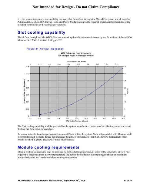
Figure 21 Airflow impedance<br />
The Slot cooling capability shall be provided by the system manufacturer, in terms of the Slot impedance curve and<br />
the Slot fan flow curve for each Slot.<br />
To ensure consistent cooling performance across all Slots within the system, Slots not populated with Modules shall<br />
incorporate an air blocking device that increases the airflow impedance of that Slot. Airflow management filler<br />
panels installed in empty Slots satisfy these requirements.<br />
Module cooling requirements<br />
Module cooling requirements shall be specified by the Module manufacturer, in terms of the volumetric airflow rate<br />
required to meet maximum allowed temperature rise across the Module at the operating condition of maximum<br />
power dissipation and maximum inlet operating temperature.<br />
<strong>PICMG</strong>® MTCA.0 Short Form Specification, September 21 st , 2006 30 of 34