MicroTCA TM - PICMG
MicroTCA TM - PICMG
MicroTCA TM - PICMG

You also want an ePaper? Increase the reach of your titles
YUMPU automatically turns print PDFs into web optimized ePapers that Google loves.
Not Intended for Design - Do not Claim Compliance<br />
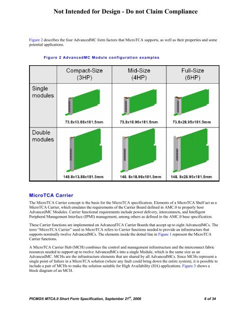
Figure 2 describes the four AdvancedMC form factors that <strong>MicroTCA</strong> supports, as well as their properties and some<br />
potential applications.<br />
Figure 2 AdvancedMC Module configuration examples<br />
<strong>MicroTCA</strong> Carrier<br />
The <strong>MicroTCA</strong> Carrier concept is the basis for the <strong>MicroTCA</strong> specification. Elements of a <strong>MicroTCA</strong> Shelf act as a<br />
<strong>MicroTCA</strong> Carrier, which emulates the requirements of the Carrier Board defined in AMC.0 to properly host<br />
AdvancedMC Modules. Carrier functional requirements include power delivery, interconnects, and Intelligent<br />
Peripheral Management Interface (IPMI) management, among others as defined in the AMC.0 base specification.<br />
These Carrier functions are implemented on AdvancedTCA Carrier Boards that accept up to eight AdvancedMCs. The<br />
term “<strong>MicroTCA</strong> Carrier” used in <strong>MicroTCA</strong> refers to Carrier functions needed to provide an infrastructure that<br />
supports nominally twelve AdvancedMCs. The elements inside the dotted line in Figure 1 represent the <strong>MicroTCA</strong><br />
Carrier functions.<br />
A <strong>MicroTCA</strong> Carrier Hub (MCH) combines the control and management infrastructure and the interconnect fabric<br />
resources needed to support up to twelve AdvancedMCs into a single Module, which is the same size as an<br />
AdvancedMC. MCHs are the infrastructure elements that are shared by all AdvancedMCs. Since MCHs represent a<br />
single point of failure in a <strong>MicroTCA</strong> solution (where any fault could bring down the entire system), it is possible to<br />
include a pair of MCHs to make the solution suitable for High Availability (HA) applications. Figure 3 shows a<br />
block diagram of an MCH.<br />
<strong>PICMG</strong>® MTCA.0 Short Form Specification, September 21 st , 2006 6 of 34