MicroTCA TM - PICMG
MicroTCA TM - PICMG
MicroTCA TM - PICMG
Create successful ePaper yourself
Turn your PDF publications into a flip-book with our unique Google optimized e-Paper software.
Not Intended for Design - Do not Claim Compliance<br />
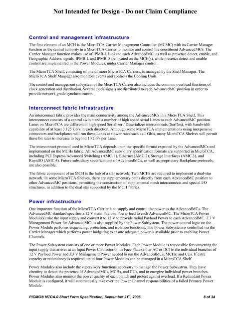
Control and management infrastructure<br />
The first element of an MCH is the <strong>MicroTCA</strong> Carrier Management Controller (MCMC) with its Carrier Manager<br />
function as the central authority in a <strong>MicroTCA</strong> Carrier to monitor and control the constituent AdvancedMCs. The<br />
Carrier Manager function makes use of IPMB-L Links to each AdvancedMC, as well as presence detect, enable, and<br />
Geographic Address signals. IPMB-L and IPMB-0 are located on the MCH(s), while presence detect and enable<br />
control are implemented in the Power Modules, under Carrier Manager control.<br />
The <strong>MicroTCA</strong> Shelf, consisting of one or more <strong>MicroTCA</strong> Carriers, is managed by the Shelf Manager. The<br />
<strong>MicroTCA</strong> Shelf Manager also monitors events and controls the Cooling Units.<br />
The control and management subsystem of the <strong>MicroTCA</strong> Carrier also includes the common overhead functions of<br />
clock generation and distribution. Several clock signals are distributed to each AdvancedMC position in order to<br />
provide network grade synchronization.<br />
Interconnect fabric infrastructure<br />
An interconnect fabric provides the main connectivity among the AdvancedMCs in a <strong>MicroTCA</strong> Shelf. This<br />
interconnect consists of a central switch and a number of high speed serial Lanes to each AdvancedMC position.<br />
Lanes on <strong>MicroTCA</strong> are differential high speed Serializer / Deserializer interconnects (SerDes), with bandwidth<br />
capability of at least 3.125 Gb/s in each direction. Although some <strong>MicroTCA</strong> implementations using inexpensive<br />
connectors and backplanes will run these Lanes at slower rates such as 1 Gb/s, many <strong>MicroTCA</strong> Shelves will permit<br />
these bit rates to increase to beyond 10 Gb/s per Lane.<br />
The interconnect protocol used in <strong>MicroTCA</strong> depends upon the specific format expected by the AdvancedMCs and<br />
implemented on the MCHs fabric. All AdvancedMC subsidiary specification formats are supported in <strong>MicroTCA</strong>,<br />
including PCI Express/Advanced Switching (AMC. 1), Ethernet (AMC.2), Storage Interfaces (AMC.3), and<br />
RapidIO (AMC.4). Future subsidiary specifications of AdvancedMCs, as well as proprietary Backplane protocols,<br />
are also possible.<br />
The fabric component of an MCH is the hub of a star network. Two MCHs are required to implement a dual-star<br />
network. In some <strong>MicroTCA</strong> Shelves, there are supplementary paths directly from each AdvancedMC position to<br />
other AdvancedMC positions, permitting the construction of supplemental mesh interconnects and special I/O<br />
structures, in addition to the dual star supported by the MCH fabrics.<br />
Power infrastructure<br />
One important function of the <strong>MicroTCA</strong> Carrier is to supply and control the power to the AdvancedMCs. The<br />
AdvancedMC standard specifies a 12 V main Payload Power feed to each AdvancedMC. The <strong>MicroTCA</strong> Power<br />
Module(s) take the input supply and convert it to 12 V to provide radial Payload Power to each AdvancedMC. 3.3 V<br />
Management Power for AdvancedMCs is also supplied by the Power Subsystem. The power control logic on the<br />
Power Module performs sequencing, protection, and isolation functions. The Power Subsystem is controlled via the<br />
Carrier Manager which performs power budgeting to ensure adequate power is available prior to enabling Power<br />
Channels.<br />
The Power Subsystem consists of one or more Power Modules. Each Power Module is responsible for converting the<br />
input supply that arrives at an Input Power Connector on its Face Plate (either AC or DC) to the individual branches of<br />
12 V Payload Power and 3.3 V Management Power needed to run the AdvancedMCs, MCHs, and CUs. If extra<br />
capacity or redundancy is required, up to four Power Modules can be managed in a <strong>MicroTCA</strong> Shelf.<br />
Power Modules also include the supervisory functions necessary to manage the Power Subsystem. They have<br />
circuitry to detect the presence of AdvancedMCs, MCHs, and CUs, and to energize individual power branches.<br />
Power Modules also monitor the power quality of each branch and protect against overload. If a Redundant Power<br />
Module is configured, it will automatically take over the Power Channel responsibilities of a failed Primary Power<br />
Module.<br />
<strong>PICMG</strong>® MTCA.0 Short Form Specification, September 21 st , 2006 8 of 34


