MicroTCA TM - PICMG
MicroTCA TM - PICMG
MicroTCA TM - PICMG

You also want an ePaper? Increase the reach of your titles
YUMPU automatically turns print PDFs into web optimized ePapers that Google loves.
Not Intended for Design - Do not Claim Compliance<br />
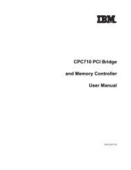
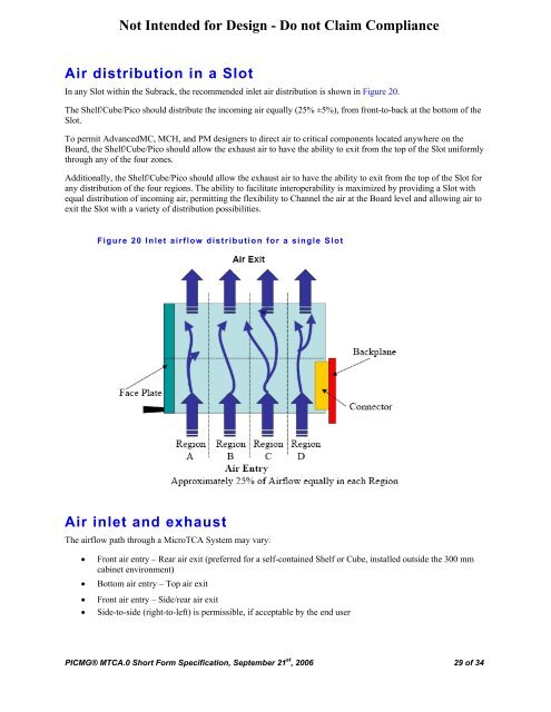
Air distribution in a Slot<br />
In any Slot within the Subrack, the recommended inlet air distribution is shown in Figure 20.<br />
The Shelf/Cube/Pico should distribute the incoming air equally (25% ±5%), from front-to-back at the bottom of the<br />
Slot.<br />
To permit AdvancedMC, MCH, and PM designers to direct air to critical components located anywhere on the<br />
Board, the Shelf/Cube/Pico should allow the exhaust air to have the ability to exit from the top of the Slot uniformly<br />
through any of the four zones.<br />
Additionally, the Shelf/Cube/Pico should allow the exhaust air to have the ability to exit from the top of the Slot for<br />
any distribution of the four regions. The ability to facilitate interoperability is maximized by providing a Slot with<br />
equal distribution of incoming air, permitting the flexibility to Channel the air at the Board level and allowing air to<br />
exit the Slot with a variety of distribution possibilities.<br />
Figure 20 Inlet airflow distribution for a single Slot<br />
Air inlet and exhaust<br />
The airflow path through a <strong>MicroTCA</strong> System may vary:<br />
• Front air entry – Rear air exit (preferred for a self-contained Shelf or Cube, installed outside the 300 mm<br />
cabinet environment)<br />
• Bottom air entry – Top air exit<br />
• Front air entry – Side/rear air exit<br />
• Side-to-side (right-to-left) is permissible, if acceptable by the end user<br />
<strong>PICMG</strong>® MTCA.0 Short Form Specification, September 21 st , 2006 29 of 34