You also want an ePaper? Increase the reach of your titles
YUMPU automatically turns print PDFs into web optimized ePapers that Google loves.
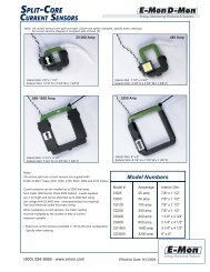
6.4.1 Current Sensor WiringCLASS <strong>3200</strong> METEROnce the current sensors are installed onto their appropriate phase conductors, youcan begin terminating the current sensors onto the <strong>Class</strong> <strong>3200</strong> main board. Thecurrent sensors can be extended up to 500 feet for remote monitoring applications. Toextend the length of the wires, use #22 AWG twisted-pair wire with one white and oneblack wire.The easiest way to connect the current sensors is to use the meter’s built-in currentsensor diagnostics. To do this, there must be at least 1% of the meter’s current rating(amps) flowing in each of the conductors being monitored. The <strong>Class</strong> <strong>3200</strong> meter’sdiagnostic program (on the 4-line display) will provide data to ensure that the currentsensor installation is done properly.The current sensor connection points are located at the bottom right of the main powerboard. These are TB2, TB3, and TB4. Each sensor connects to two terminals onelabeled “Black” and the other “White.” Current sensors should be connected to themeter one at a time and verified using the current sensor diagnostic program.Connect one of the current sensors to the TB2 terminals (Phase A). Tighten theterminal to 4.5 in-lb. Wait 5 seconds and look at the meter display.If the meter displays an error message (see below), remove the wires from TB2 (PhaseA) and install them on TB3 (Phase B). if an error message occurs with the sensorattached toTB3, try again on TB4 (Phase C). The wiring will be correct when the errorindication message is gone.NOTE:If the power factor being monitored is


