Stage II Vapour Recovery
Stage II Vapour Recovery
Stage II Vapour Recovery

You also want an ePaper? Increase the reach of your titles
YUMPU automatically turns print PDFs into web optimized ePapers that Google loves.
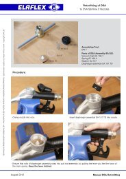
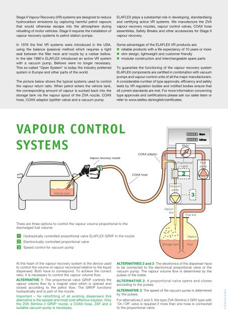
<strong>Stage</strong> <strong>II</strong> <strong>Vapour</strong> <strong>Recovery</strong> (VR) systems are designed to reducehydrocarbon emissions by capturing harmful petrol vapoursthat would otherwise escape into the atmosphere duringrefuelling of motor vehicles. <strong>Stage</strong> <strong>II</strong> requires the installation ofvapour recovery systems to petrol station pumps.In 1976 the first VR systems were introduced in the USA,using the balance (passive) method which requires a tightseal between the filler neck and nozzle by a rubber bellow.In the late 1980's ELAFLEX introduced an active VR systemwith a vacuum pump. Bellows were no longer necessary.This so-called "Open System" is today the industry preferredsystem in Europe and other parts of the world.The picture below shows the typical systems used to controlthe vapour return ratio. When petrol enters the vehicle tank,the corresponding amount of vapour is sucked back into thestorage tank via the vapour spout of the ZVA nozzle, COAXhose, COAX adaptor (splitter valve) and a vacuum pump.ELAFLEX plays a substantial role in developing, standardisingand certifying active VR systems. We manufacture the ZVAvapour recovery nozzles, vapour control valves, COAX hoseassemblies, Safety Breaks and other accessories for <strong>Stage</strong> <strong>II</strong>vapour recovery.Some advantages of the ELAFLEX VR products are:• reliable products with a life expectancy of 10 years or more• slim design, lightweight and customer friendly• modular construction and interchangeable spare partsTo guarantee the functioning of the vapour recovery systemELAFLEX components are certified in combination with vacuumpumps and vapour control units of all the major manufacturers.A considerable number of type approvals, efficiency and safetytests by VR regulation bodies and notified bodies ensure thatall current standards are met. For more information concerningtype approvals and certifications please ask our sales team orrefer to www.elaflex.de/english/certificates.<strong>Vapour</strong> ControlSystems<strong>Vapour</strong> recovery nozzleCOAX adaptorMeterProportionalvalveFuelpumpCOAX hose2Vehicle tankVacuumpump3<strong>Vapour</strong>lineFuel lineThere are three options to control the vapour volume proportional to thedischarged fuel volume:• 1• 2 Electronically controlled proportional valve• 3 Speed control for vacuum pumpHydraulically controlled proportional valve ELAFLEX GRVP in the nozzleStorage tank<strong>Vapour</strong>FuelAt the heart of the vapour recovery system is the device usedto control the volume of vapour recovered relative to the liquiddispensed. Both have to correspond. To achieve the correctratio, it is necessary to control the vapour volume flow.Alternative 1: The proportional valve GRVP controls thevapour volume flow by a magnet valve which is opened andclosed according to the petrol flow. The GRVP functionshydraulically and is part of the nozzle.Important – for retrofitting of all existing dispensers thisalternative is the easiest and most cost-effective solution. Onlythe ZVA Slimline 2 GRVP nozzle, a COAX hose, ZAF and asuitable vacuum pump is necessary.Alternatives 2 and 3: The electronics of the dispenser haveto be connected to the electronical proportional valve or thevacuum pump. The vapour volume flow is determined by thepulses of the meter.Alternative 2: A proportional valve opens and closesaccording to the pulses.Alternative 3: The speed of the vacuum pump is determinedby the pulses.For alternatives 2 and 3, the type ZVA Slimline 2 GRV type with'On / Off' valve is required if more than one hose is connectedto the proportional valve.© ELAFLEX 9.2010