Wall-Mounted Humidity Sensor (P/N 203-5751) - icemeister.net
Wall-Mounted Humidity Sensor (P/N 203-5751) - icemeister.net
Wall-Mounted Humidity Sensor (P/N 203-5751) - icemeister.net

You also want an ePaper? Increase the reach of your titles
YUMPU automatically turns print PDFs into web optimized ePapers that Google loves.
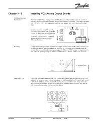
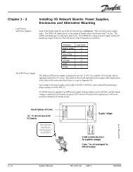
TECHNICAL BULLETINPart #: 026-4806 Revision 0 Date: 02/26/2003<strong>Wall</strong>-<strong>Mounted</strong> <strong>Humidity</strong> <strong>Sensor</strong> (P/N <strong>203</strong>-<strong>5751</strong>)Installation InstructionsCPC specs a wall-mounted relative humidity (RH) sensor with a 0-5VDC output for use in buildingcontrol and anti-sweat control applications using CPC input boards.SpecificationsSensing Element Digitally profiled thin-film capacitive Analog Output 0-5VDC; 3-wire, observe polarityAccuracy ±2% RH over the range 20%-90% RH Scaling 0-100% RHStability ±1%@ 20°C (68°F) annually for 2 years Input Power 12VDCOperating<strong>Humidity</strong> RangeTemperatureCoefficientChoosing a Mounting LocationMount the sensor indoors in a central location within the zone to be measured, away from doors,windows, vents, heaters, and outside walls that could affect temperature readings. The sensorshould be at least four feet from the floor, and no higher than necessary to prevent tampering.Mounting0-100% RH Enclosure High-impact ABS plastic, plenum ratedUL94-5VA, White±0.03% RH /°C over 0-60°C (32-140°F) EMCConformance1. Insert a screwdriver into the gap in the plastic on the bottomside of the sensor enclosure, and pry the front part of theenclosure away from the rear mounting plate. Pull the frontaway from the mounting plate until the top separates from themounting plate.2. Remove the punch out above the wiring connector so that thesensor cable can be run into the sensor enclosure (see Figure1).3. Use the pre-made holes to mount the plate on a junction boxusing the screws provided, or mount it against a wall or riser.Do not mount the plate upside down or sideways. The plateshould be mounted with the terminal block toward the bottom.4. If necessary, drill or cut a hole in the wall to allow the sensorcable to be run through the wall into the sensor’s terminalblock.EN 50081-1, EN 50082-1, EN 61000-4-4,EN 61000-4-5, EN 61000-4-3,ENV 50204, EN 61000-4-6Figure 1 - <strong>Humidity</strong> <strong>Sensor</strong> - Exploded ViewCOMPUTER PROCESS CONTROLS - http://www.cpcus.com/ Page 1
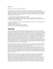
Technical Bulletin - <strong>Wall</strong>-<strong>Mounted</strong> <strong>Humidity</strong> <strong>Sensor</strong> (P/N <strong>203</strong>-<strong>5751</strong>) Installation InstructionsPart #: 026-4806 Revision 0 Date: 02/26/2003Wiring1. Use Belden #8771 shielded three-conductor cableor equivalent.2. Connect the RED, BLACK, and WHITE wires tothe screw terminals the sensor’s connector asshown in Figure 2. Clip the SHIELD wire.3. Connect the SHIELD and BLACK wires to the0V terminal of the input board. Connect theWHITE wire to the SIG terminal of the inputboard.4. Connect the RED wire to the +12V power terminalon the input board.Figure 2 - <strong>Sensor</strong> and Input Board Wiring5. Locate the input dip switch for the sensor point, and set to the OFF position (LEFT for MultiFlex, DOWN for 16AI). Refer tothe input board’s user manual for locations of the input dip switches.Finishing the InstallationOnce the back plate of the sensor is mounted and the sensor andboard wiring is complete:1. Attach the sensor circuit board enclosure to the mounting plate. Push the top of thefront part onto the mounting plate so the hooked mounting tabs fit underneath thecircuit board enclosure, and push the bottom part down so that the three prongs onthe back of the circuit board fit into the wiring connector. Continue pushing untilthe front part is flush with the mounting plate.2. Before putting the cover on the sensor circuit board enclosure, check the position ofthe switch and the jumper on the front of the circuit board. The switch should be setto the VOLTS (left) position. The jumper should be set to the 5V position (acrossthe center and right pins). If either or both of these are in the wrong position, setthem to the correct position. Refer to Figure 3 for positioning.3. Replace the front cover by inserting the hooked tab at the top of the cover into theslot on the front of the circuit board enclosure so that it snaps into place. Press thebottom of the cover until it snaps into the enclosure.Figure 3 - Switch & Jumper SettingsCalibration and ReplacementThe sensing element of the <strong>203</strong>-<strong>5751</strong> wall-mount RH sensor is pre-calibrated and will require nophysical adjustment. If the sensor drifts over time, the sensor can be ‘recalibrated’ by replacingthe pluggable sensing element. Contact CPC to order replacement elements (P/N <strong>203</strong>-5795).To replace a sensor element, use a screwdriver to pry the sensor circuit board off the mountingplate. The sensing element is located on the back of the circuit board (see Figure 1). Note the orientationof the sensor element before unplugging it and plug the new sensor element in usingthe same orientation. Replace the circuit board when finished. There is no other calibrationmethod needed, and no adjustments are present in the unit.Note: Do not expose sensor element to the fumes of curing RTV silicone rubber. Doing sowill damage the calibration of the element.COMPUTER PROCESS CONTROLS - http://www.cpcus.com/ Page 2