Selective MOCVD of titanium oxide and zirconium oxide thin films ...
Selective MOCVD of titanium oxide and zirconium oxide thin films ...
Selective MOCVD of titanium oxide and zirconium oxide thin films ...
- No tags were found...

Create successful ePaper yourself
Turn your PDF publications into a flip-book with our unique Google optimized e-Paper software.
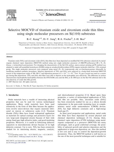
ARTICLE IN PRESSJournal <strong>of</strong> Physics <strong>and</strong> Chemistry <strong>of</strong> Solids 69 (2008) 128–132www.elsevier.com/locate/jpcs<strong>Selective</strong> <strong>MOCVD</strong> <strong>of</strong> <strong>titanium</strong> <strong>oxide</strong> <strong>and</strong> <strong>zirconium</strong> <strong>oxide</strong> <strong>thin</strong> <strong>films</strong>using single molecular precursors on Si(1 0 0) substratesB.-C. Kang a, , D.-Y. Jung a , R.A. Fischer b , J.-H. Boo aa Department <strong>of</strong> Chemistry, Institute <strong>of</strong> Basic Science, Sungkyunkwan University, Suwon 440-746, Republic <strong>of</strong> Koreab Organometallics <strong>and</strong> Materials Chemistry, Ruhr-University Bochum, Universitässtr. 150, Bochum 44780, GermanyReceived 23 September 2006; received in revised form 23 June 2007; accepted 10 August 2007AbstractTitanium <strong>oxide</strong> (TiO 2 ) <strong>and</strong> <strong>zirconium</strong> <strong>oxide</strong> (ZrO 2 ) <strong>thin</strong> <strong>films</strong> have been deposited on modified Si(1 0 0) substrates selectively by metalorganicchemical vapor deposition (<strong>MOCVD</strong>) method using new single molecular precursor <strong>of</strong> [M(O i Pr) 2 (tbaoac) 2 ](M¼ Ti, Zr;tbaoac ¼ tertiarybutyl-acetoacetate). For changing the characteristic <strong>of</strong> the Si(1 0 0) surface, micro-contact printing (mCP) method wasadapted to make self-assembled monolayers (SAMs) using an octadecyltrichlorosilane (OTS) organic molecule which has –CH 3 terminalgroup. The single molecular precursors were prepared using metal (Ti, Zr) isoprop<strong>oxide</strong> <strong>and</strong> tert-butylacetoacetate (tbaoacH) bymodifying st<strong>and</strong>ard synthetic procedures. <strong>Selective</strong> depositions <strong>of</strong> TiO 2 <strong>and</strong> ZrO 2 were achieved in a home-built horizontal <strong>MOCVD</strong>reactor in the temperature range <strong>of</strong> 300–500 1C <strong>and</strong> deposition pressure <strong>of</strong> 1 10 3 –3 10 2 Torr. N 2 gas (5 sccm) was used as a carriergas during film depositions. TiO 2 <strong>and</strong> ZrO 2 <strong>thin</strong> <strong>films</strong> were able to deposit on the hydrophilic area selectively. The difference in surfacecharacteristics (hydrophobic/hydrophilic) between the OTS SAMs area <strong>and</strong> the SiO 2 or Si–OH layer on the Si(1 0 0) substrate led to thesite-selectivity <strong>of</strong> <strong>oxide</strong> <strong>thin</strong> film growth.r 2007 Elsevier Ltd. All rights reserved.Keywords: A. Oxides; A. Thin film; B. Vapor deposition; D. Surface properties1. IntroductionOxide materials have a wealth <strong>of</strong> interesting physicalproperties that can be used for various technologicalapplications. Many <strong>oxide</strong> materials have been usedextensively in the form <strong>of</strong> <strong>thin</strong> <strong>films</strong> because the applicationsinvolve micro-devices that require materials fabricatedon micron or submicron scales [1,2]. Titaniumdi<strong>oxide</strong> (TiO 2 ) <strong>films</strong> have found widespread applicationas materials for optical coatings <strong>and</strong> protective layers forvery large-scale integrated circuits because <strong>of</strong> their wideenergy b<strong>and</strong> gap, high refractive index, <strong>and</strong> good insulatingproperties. Moreover, it is useful in fabricating dielectriccapacitors in microelectronic devices because <strong>of</strong> its highdielectric constant. Up to now, TiO 2 has been extensivelystudied for its interesting electric, magnetic, catalytic, Corresponding author. Tel.: +82 31 290 5972; fax: +82 31 290 7075.E-mail address: bchkang@empal.com (B.-C. Kang).<strong>and</strong> electrochemical properties [3–6]. Based upon theseproperties, a variety <strong>of</strong> technological applications <strong>of</strong> TiO 2<strong>thin</strong> film are possible. Also, <strong>zirconium</strong> <strong>oxide</strong> (ZrO 2 )has been extensively studied for use as a silicon di<strong>oxide</strong>replacement in the gate-<strong>oxide</strong> insulating layer in complementarymetal <strong>oxide</strong> semiconductor (CMOS) devices.ZrO 2 has high dielectric constants <strong>and</strong> a high-energyb<strong>and</strong> gap [7].As these good properties <strong>and</strong> applications, metal <strong>oxide</strong><strong>thin</strong> <strong>films</strong> have been deposited by several physical <strong>and</strong>chemical deposition techniques [8–11]. Among them,chemical vapor deposition (CVD) technique using metalorganiccompound as a precursor (<strong>MOCVD</strong>) has manyadvantages, such as good conformal coverage, the possibility<strong>of</strong> epitaxial growth <strong>and</strong> selective deposition <strong>and</strong> theapplication to large-area deposition, etc. Also this methodis low cost <strong>and</strong> is easy to control the deposition/growthparameters. Thus, the <strong>MOCVD</strong> method is well known asthe one <strong>of</strong> the most powerful techniques <strong>and</strong> is suitable for0022-3697/$ - see front matter r 2007 Elsevier Ltd. All rights reserved.doi:10.1016/j.jpcs.2007.08.008
ARTICLE IN PRESSB.-C. Kang et al. / Journal <strong>of</strong> Physics <strong>and</strong> Chemistry <strong>of</strong> Solids 69 (2008) 128–132 129stoichiometric <strong>and</strong> micro-structured <strong>thin</strong> film deposition.The patterning <strong>of</strong> <strong>thin</strong> film is <strong>of</strong> considerable scientific <strong>and</strong>technological interest. S<strong>of</strong>t lithography is a method tomake micro/nano size patterns <strong>and</strong> structures simply usingorganic materials without involving high energy. Inparticular, micro-contact printing (mCP) is a very convenient<strong>and</strong> nonphotolithographic technique that cangenerate patterned features <strong>of</strong> self-assembled monolayers(SAMs) on various surfaces [12]. The ability to control thewettability <strong>of</strong> a solid surface is important <strong>and</strong> useful in arange <strong>of</strong> technological applications [13–15]. In addition,the mCP technique shows that hydrophobic patterns withmicron dimensions can be formed on hydrophilic surfacesavoiding the use <strong>of</strong> photolithographic-type procedures. Xia<strong>and</strong> Whitesides [13] <strong>and</strong> Folch <strong>and</strong> Schmidt [16] presentedthe current state <strong>of</strong> development <strong>of</strong> s<strong>of</strong>t lithographictechniques <strong>and</strong> areas in which these techniques findapplications. The authors suggested the mCP techniquecould apply to micro-electro-mechanical system (MEMS),sensors, <strong>and</strong> microelectronics with large patterning featuresover 100 mm scale, because small-area wafer <strong>and</strong> largelinewidths are perfectly suited for most those applications.Earlier, we reported deposition <strong>of</strong> patterned TiO 2 <strong>thin</strong><strong>films</strong> using <strong>titanium</strong>(IV) isoprop<strong>oxide</strong> [Ti(O i Pr) 4 ] by<strong>MOCVD</strong> on Si(1 0 0) substrates where the surface was firstmodified by an octadecyltrichlorosilane (OTS) [17]. Theaim <strong>of</strong> the work presented here is to fabricate <strong>thin</strong> <strong>films</strong> <strong>and</strong>micro/nano patterning <strong>of</strong> TiO 2 <strong>and</strong> ZrO 2 <strong>thin</strong> <strong>films</strong> byusing <strong>of</strong> new single molecular precursors. Herein, we reportthat site-selective <strong>MOCVD</strong> <strong>of</strong> TiO 2 <strong>and</strong> ZrO 2 <strong>thin</strong> <strong>films</strong>using bis-isopropoxy-bis-tertiarybutyl-acetoacetate <strong>titanium</strong>[Ti(O i Pr) 2 (tbaoac) 2 ] as precursors on OTS patternedSi(1 0 0) substrates.2. ExperimentalThe polydimethylsiloxane [–Si(CH 3 ) 2 O–] n (PDMS)stamps were used for mCP <strong>and</strong> OTS [CH 3 (CH 2 ) 17 SiCl 3 )]SAMs were fabricated according to a previously reportedprocedure [13]. A solution <strong>of</strong> OTS in dry hexane was usedas the ‘‘ink.’’ The OTS solution was applied to the PDMSstamp using a spin coater. Then, the stamp was broughtinto contact with the Si(1 0 0) substrate whose surfacecontains a native <strong>oxide</strong> layer. The thermal stability <strong>of</strong> theOTS SAMs on the Si(1 0 0) substrate is so strong that itcan endure around 450 1C in a vacuum condition. Afterprinting, <strong>thin</strong> <strong>films</strong> were deposited on these OTS patternedSi(1 0 0) substrates by <strong>MOCVD</strong> using new metal-organicprecursors, [M(O i Pr) 2 (tbaoac) 2 ] (M ¼ Ti, Zr; tbaoac ¼tertiarybutyl-acetoacetate) as a single molecular precursor.Ti(O i Pr) 2 (tbaoac) 2 exists as pale-yellow crystalline solids atroom temperature, having a melting point 58 1C <strong>and</strong>Zr(O i Pr) 2 (tbaoac) 2 is a white crystalline solid with 45 1Cmelting point. The details <strong>of</strong> the synthesis <strong>and</strong> characterization<strong>of</strong> the compounds is reported in the literature[18,19]. The OTS patterned Si(1 0 0) substrate was pretreatedwith ethanol <strong>and</strong> de-ionized (DI) water in anultrasonic cleaner without acid treatment to protect theOTS patterning from being destroyed. The CVD experimentswere performed in a homebuilt <strong>MOCVD</strong> system.Nitrogen was used as the carrier gas (5 sccm). The basepressure <strong>of</strong> the <strong>MOCVD</strong> apparatus was 1 10 3 Torr, <strong>and</strong>the working pressure was kept in the range <strong>of</strong> 30–50 mTorr.The precursor bottle was heated at 80 1C. The deposition <strong>of</strong>TiO 2 <strong>thin</strong> <strong>films</strong> was carried out at 300–400 1C for 0.5–1 h.And the depositions <strong>of</strong> ZrO 2 <strong>thin</strong> <strong>films</strong> were performed at450–500 1C for a period <strong>of</strong> 2–4 h. The as-grown <strong>films</strong> werecharacterized by optical microscopy (OM), scanningelectron microscopy (SEM), energy dispersive X-ray(EDX), atomic force microscopy (AFM) <strong>and</strong> micro-Raman spectroscopy.3. Results <strong>and</strong> discussion<strong>Selective</strong>ly deposited TiO 2 <strong>thin</strong> <strong>films</strong> can be identified byoptical microscopy (OM). Fig. 1 shows an OM image <strong>of</strong>the deposited TiO 2 <strong>thin</strong> film that was selectively grown onthe OTS patterned Si(1 0 0) substrate at 400 1C for 1 h. Therelatively dark area corresponds to the TiO 2 deposited area<strong>and</strong> the bright area is OTS SAMs area.SEM <strong>and</strong> AFM analyses were performed to see thesurface morphologies <strong>of</strong> the selectively deposited TiO 2 <strong>thin</strong><strong>films</strong>. Fig. 2 shows the SEM image <strong>and</strong> EDX data(see inset) <strong>of</strong> the selectively grown TiO 2 <strong>thin</strong> film on theOTS patterned Si(1 0 0) substrate. It was observed that theimages (which consist <strong>of</strong> two different contrasts shown inFig. 2) match well with the OM data. Moreover, it is seenthat boundary shape between the OTS SAMs area <strong>and</strong> theTiO 2 deposited area is also very sharp <strong>and</strong> clear. In order toidentify the composition <strong>of</strong> both dark (TiO 2 film) <strong>and</strong>bright areas (OTS SAMs), we utilized the EDX analysisshown in the inset in Fig. 2. In the case <strong>of</strong> bright area, theatomic ratio (%) <strong>of</strong> Ti <strong>and</strong> O was nearly 1:2, while inthe dark area there was no evidence <strong>of</strong> Ti <strong>and</strong> O elements.Fig. 1. Optical microscope image <strong>of</strong> a TiO 2 <strong>thin</strong> film deposited on theOTS patterned Si(1 0 0) substrate. The dark image is TiO 2 deposited area<strong>and</strong> the bright image is OTS SAMs area.
130ARTICLE IN PRESSB.-C. Kang et al. / Journal <strong>of</strong> Physics <strong>and</strong> Chemistry <strong>of</strong> Solids 69 (2008) 128–132Fig. 2. SEM image <strong>of</strong> a TiO 2 <strong>thin</strong> film deposited on the OTS patternedSi(1 0 0) substrate. Inset shows EDX spectra obtained from the selectivelygrown TiO 2 film (A) <strong>and</strong> OTS SAMs surface (B).Fig. 4. Micro-Raman spectra <strong>of</strong> (a) Si(1 0 0) substrate, (b) OTS SAMsarea, <strong>and</strong> (c) TiO 2 deposited area (Raman laser radiation: 514.5 nm,20 mW).Fig. 3. (a) 3D AFM image <strong>of</strong> selective growth <strong>of</strong> TiO 2 <strong>thin</strong> film onSi(1 0 0) surface. (b) 2D AFM image <strong>of</strong> the same film as (a), <strong>and</strong> heightpr<strong>of</strong>ile obtained from the direction <strong>of</strong> black line area.This is a good agreement with reported data <strong>of</strong> selectivegrowth <strong>of</strong> TiO 2 <strong>thin</strong> film with Ti(O i Pr) 2 (tbaoac) 2 [18] <strong>and</strong><strong>of</strong> the CVD grown TiO 2 <strong>thin</strong> <strong>films</strong> with Ti(O i Pr) 4 [20].Fig. 3(a) shows the 3D AFM image <strong>of</strong> the selectivelygrown TiO 2 <strong>thin</strong> film on OTS SAMs patterned Si(1 0 0)substrate at 400 1C. The selective deposition <strong>of</strong> <strong>thin</strong> film<strong>and</strong> the sharp boundary between TiO 2 <strong>thin</strong> film area <strong>and</strong>OTS SAMs area was clearly seen. Fig. 3(b) also shows the2D AFM image obtained from the same film as Fig. 3(a).From the images <strong>of</strong> Fig. 3(a) <strong>and</strong> (b), also we can see twodifferent contrasts similar to SEM images, indicating goodselectivity. With the height pr<strong>of</strong>ile (see inset) <strong>of</strong> the 2DAFM image, we can reconfirm the selective growth <strong>of</strong> TiO 2<strong>thin</strong> film <strong>and</strong> the TiO 2 <strong>thin</strong> film was able to selectivelydeposit on 10 mm area with thickness <strong>of</strong> about 120 nm.The clear <strong>and</strong> convincing evidence <strong>of</strong> selective growthwas obtained by micro-Raman analysis with a 514 nm laser<strong>and</strong> 20 mW power. Fig. 4 shows the micro-Raman spectra<strong>of</strong> the Si(1 0 0) substrate (a), OTS SAMs printed area(b) <strong>and</strong> TiO 2 deposited area (c), respectively. In the case <strong>of</strong>(a) <strong>and</strong> (b), there were no characteristic b<strong>and</strong>s except forthe peaks originated from the Si(1 0 0) substrate. However,in Fig. 4(c), we clearly found that the three b<strong>and</strong>scorresponding to the anatase TiO 2 Raman active fundamentalmodes, are recorded at 144 cm 1 (E g ), 399 cm 1(B 1g ), <strong>and</strong> 639 cm 1 (E g ). The b<strong>and</strong> positions were in very agood agreement with published data on either polycrystallinepowders or monocrystals [21,22]. Moreover, the b<strong>and</strong>sdue to rutile <strong>and</strong> brookite phase <strong>of</strong> TiO 2 were not observed.With these data, we were able to conclude that the anatasephase TiO 2 <strong>thin</strong> film was able to mainly grow on theSi(1 0 0) substrate on which OTS SAMs were not covered,strictly speaking, a native <strong>oxide</strong> layer on Si(1 0 0) surface.This result proved the selectivity <strong>of</strong> TiO 2 <strong>thin</strong> film on theOTS patterned Si(1 0 0) substrate.Selectivity <strong>of</strong> deposited ZrO 2 film can be identified byoptical microscopy (OM) images. Fig. 5 shows an OMimage <strong>of</strong> the deposited ZrO 2 <strong>films</strong> on OTS patternedSi(1 0 0) substrate at 450 1C for 2 h. It shows contrastbetween OTS SAMs area <strong>and</strong> ZrO 2 <strong>thin</strong> <strong>films</strong> depositedregion. The relatively dark area corresponds to the ZrO 2deposited area <strong>and</strong> the bright area is OTS SAMs area.Fig. 6 shows the SEM images <strong>of</strong> selectivity grown onOTS patterned Si(1 0 0) substrate. In the case <strong>of</strong> (a), grownat 450 1C for 2 h, it shows that boundary shape between the
ARTICLE IN PRESSB.-C. Kang et al. / Journal <strong>of</strong> Physics <strong>and</strong> Chemistry <strong>of</strong> Solids 69 (2008) 128–132 131OTS SAMs area <strong>and</strong> ZrO 2 deposited area is clear.However, as the deposition time was increased up to 4 h,the boundary became very unclear. It means the ZrO 2 wasable to deposit both hydrophilic area <strong>and</strong> hydrophobicarea. We can suggest that the terminal group <strong>of</strong> OTS wasoxidized <strong>and</strong> changed its character from hydrophobic tohydrophilic or removed from the substrate surface becausethe high deposition temperature <strong>and</strong> long deposition time[25]. The morphology <strong>of</strong> ZrO 2 <strong>thin</strong> film grown on Si(1 0 0)substrate was denser <strong>and</strong> smoother than that <strong>of</strong> ZrO 2 <strong>thin</strong>film grown on OTS SAMs surface.XPS survey spectrum analysis was carried out <strong>of</strong> the asdepositedZrO 2 film grown on Si(1 0 0) substrate at 450 1C(not shown here). The strong Zr 3d <strong>and</strong> O 1s peaks wereclearly indicated. However, C 1s peak clearly appearedaround 300 eV binding energy, we can guess that thecarbon comes from the precursor during depositions <strong>and</strong>/or surface contamination from the air. Also, the O 1s <strong>and</strong>Zr 3d high-resolution XPS spectra were performed(not shown here). In the case <strong>of</strong> O 1s , there are twooxidation states attributed to O 2 <strong>and</strong> OH species at thebinding energy <strong>of</strong> about 532 <strong>and</strong> 530 eV. We can ensurethat the OH peak is just a surface contamination peakprobably originated from H 2 O in the air. The Zr 3d5/2 peakobserved as a single peak at binding energy <strong>of</strong> 182.2 eV,which is a good agreement to Zr 4+ .Fig. 7 shows the 3D AFM image <strong>of</strong> selectively grownZrO 2 <strong>thin</strong> film on OTS SAMs patterned Si(1 0 0) substrateat 450 1C for 2 h. The selectivity <strong>of</strong> <strong>thin</strong> film <strong>and</strong> the sharpboundary between ZrO 2 <strong>thin</strong> film area <strong>and</strong> OTS SAMs areclearly distinguished. The thickness <strong>of</strong> deposited ZrO 2 <strong>thin</strong>film was approximately 30–40 nm. The growth rate <strong>of</strong> ZrO 2<strong>thin</strong> <strong>films</strong> using Zr(O i Pr) 2 (tbaoac) 2 was much slower thanthat <strong>of</strong> TiO 2 <strong>thin</strong> <strong>films</strong>.OTS SAMs have been demonstrated as a promisingc<strong>and</strong>idate for a <strong>MOCVD</strong> resist layer which can block thesurface functional groups that are necessary for nucleationFig. 5. OM images <strong>of</strong> a ZrO 2 <strong>thin</strong> film deposited on the OTS patternedSi(1 0 0) substrate.Fig. 7. 3D <strong>and</strong> 2D AFM images <strong>of</strong> selective growth <strong>of</strong> a ZrO 2 <strong>thin</strong> film onSi(1 0 0) substrate.Fig. 6. SEM image <strong>of</strong> a ZrO 2 <strong>thin</strong> film deposited on the OTS patterned Si(1 0 0) substrate at (a) 450 1C for 2 h <strong>and</strong> (b) 450 1C for 4 h.
132ARTICLE IN PRESSB.-C. Kang et al. / Journal <strong>of</strong> Physics <strong>and</strong> Chemistry <strong>of</strong> Solids 69 (2008) 128–132<strong>and</strong> growth during the deposition [23]. In this experiment,OTS can prevent nucleation for TiO 2 <strong>and</strong> ZrO 2 <strong>thin</strong> film onthe SAMs surfaces because it has hydrophobic terminalgroup (–CH 3 ), i.e., there are no reaction factors forchemisorption between the metal-organic (MO) precursors<strong>and</strong> –CH 3 groups. But the MO precursors can obtainelectrons from the ‘‘base’’ originated from native <strong>oxide</strong>layers on the Si(1 0 0) surface <strong>and</strong> they can makechemisorptions with substrate very strongly. After all, <strong>thin</strong>film is able to be formed on it. However, OTS SAMs areweak in respect <strong>of</strong> thermal stability over 450 1C [25], theyshould change their identities or make some defects on theOTS SAMs area. Therefore, it is difficult to make <strong>thin</strong> <strong>films</strong>selectively on substrates by combination <strong>of</strong> mCP <strong>and</strong><strong>MOCVD</strong> methods at high temperatures. Thomas et al.showed that Ti(O i Pr) 2 (tbaoac) 2 precursor showed slightlysuperior properties in terms <strong>of</strong> evaporation behavior,deposition temperature, <strong>and</strong> smaller amount <strong>of</strong> residuematerial than those <strong>of</strong> Zr(O i Pr) 2 (tbaoac) 2 precursor [24].And Zr(O i Pr) 2 (tbaoac) 2 precursor could induce high v<strong>and</strong>er Waals force with OTS SAMs surface <strong>and</strong> lowmolecular mobility on the OTS SAMs area owing to itshigh molecular weight compared to Ti(O i Pr) 2 (tbaoac) 2 .These disadvantage factors should require a long nucleationtime on the Si(1 0 0) substrate <strong>and</strong> cause less siteselectivedeposition than that <strong>of</strong> TiO 2 in our experiment.4. ConclusionsWe successfully deposited patterned TiO 2 <strong>and</strong> ZrO 2 <strong>thin</strong><strong>films</strong> directly using a combination method <strong>of</strong> mCP <strong>and</strong><strong>MOCVD</strong> methods. New developed precursors <strong>of</strong>[M(O i Pr) 2 (tbaoac) 2 ,M¼ Ti, Zr] were used as precursorsfor TiO 2 <strong>and</strong> ZrO 2 <strong>thin</strong> <strong>films</strong>. In the case <strong>of</strong> TiO 2deposition, it showed a good selectivity growth on thepatterned Si(1 0 0) substrate. The boundaries between theOTS SAMs area <strong>and</strong> TiO 2 deposited area were very cleancut <strong>and</strong> sharp without any breaks. The micro-Ramanspectroscopy <strong>and</strong> the EDX data showed that the depositedTiO 2 <strong>thin</strong> <strong>films</strong> were stoichiometric with anatase phase. Inthe case <strong>of</strong> ZrO 2 <strong>thin</strong> <strong>films</strong>, they showed a selectivedeposition on the substrate as deposition time below 2 h;however, the selectivity disappeared above 2 h. It meansthat OTS should change or lose its identity due to hightemperature <strong>and</strong>/or long deposition time. Even though thecombination <strong>of</strong> <strong>MOCVD</strong> <strong>and</strong> mCP is a very convenienttechnique to make micro-size structures without involvingphotolithographic-type procedures, there are some limitationssuch as deposition temperature <strong>and</strong> deposition time.However, it is expected that the combination <strong>of</strong> mCP<strong>of</strong> SAMs <strong>and</strong> <strong>MOCVD</strong> is a better method for fabricatingmicro-size, various functional <strong>thin</strong> <strong>films</strong> at lowtemperatures.AcknowledgmentsThe authors gratefully acknowledge the support by theBK21 project <strong>of</strong> Ministry <strong>of</strong> Education, Korea.References[1] K.S. Goto, Solid State Electrochemistry <strong>and</strong> its Applications toSensors <strong>and</strong> Electronics Devices, Elsevier, New York, 1988.[2] L.A. Ryabova, Current Topics in Materials Science, vol. 7, North-Holl<strong>and</strong>, Amsterdam, 1981 (Chapter 5).[3] M.F. Yan, W.W. Rhodes, Grain Boundaries in Semiconductors,North-Holl<strong>and</strong>, New York, 1981.[4] J. Reintjes, M.B. Schultz, J. Appl. Phys. 39 (1968) 5254.[5] S.J. Tauster, S.C. Fung, R.L. Garten, J. Am. Chem. Soc. 100 (1978)170.[6] D.J. Dwyer, S.D. Cameron, J. Gl<strong>and</strong>, Surf. Sci. 159 (1985) 430.[7] J. Robertson, J. Vac. Sci. Technol. B 18 (2000) 1785.[8] R. Nowak, S. Maruno, Mater. Sci. Eng. A 202 (1995) 226.[9] S. Noda, J. Tepsanongsuk, Y. Tsuji, Y. Kajikawa, Y. Ogawa,H. Komiyama, J. Vac. Sci. Technol. A 22 (2) (2004) 332.[10] Y. Murayama, J. Vac. Sci. Technol. 12 (4) (1975) 818.[11] H.B. Nie, S.Y. Xu, S.J. Wang, L.P. You, Z. Yang, C.K. Ong, J. Li,T.Y.F. Liew, Appl. Phys. A 73 (2001) 229.[12] Y. Gao, K. Koumoto, Crystal Growth Des. 5 (5) (2005) 1983.[13] Y. Xia, G. Whitesides, Angew. Chem. Int. Ed. 37 (1998) 550.[14] A. Kumar, H.A. Biebuyck, N.L. Abbott, G.M. Whitesides, J. Am.Chem. Soc. 114 (1992) 9188.[15] N.L. Jeon, R.G. Nuzzo, Y. Xia, M. Mrksich, G.M. Whitesides,Langmuir 11 (1994) 3024.[16] A. Folch, M.A. Schmidt, IEEE J. Microelectromech. Syst. 8 (1)(1999) 85.[17] B.-C. Kang, J.-H. Lee, H.-Y. Chae, D.-Y. Jung, S.-B. Lee, J.-H. Boo,J. Vac. Sci. Technol. B 21 (4) (2003) 1773.[18] R. Bhakta, F. Hipler, A. Devi, S. Regnery, P. Ehrhart, R. Waser,Chem. Vap. Depos. 9 (2003) 295.[19] U. Patil, M. Winter, H.-W. Becker, A. Devi, J. Mater. Chem. 13(2003) 2177.[20] B.-C. Kang, S.-B. Lee, J.-H. Boo, Surf. Coatings Technol. 131 (2000)88.[21] Y.H. Zhang, C.C. Chan, J.F. Porter, W. Guo, J. Mater. Res. 13(1998) 2602.[22] T.D. Robert, J.D. Laude, V.M. Geskin, R. Lazzaroni, R. Gouttebaron,Thin Solid Films 440 (2003) 268.[23] R. Chen, H. Kim, P.C. McIntyre, S.F. Bent, Appl. Phys. Lett. 84(2004) 4017.[24] R. Thomas, S. Regnery, P. Ehrhart, R. Washer, U. Patil, R. Bhakta,A. Devi, Ferroelectrics 327 (2005) 111.[25] H.K. Kim, J.P. Lee, C.R. Park, H.T. Kwak, M.M. Sung, J. Phys.Chem. B 107 (2003) 4348.