ARTICLE IN PRESSB.-C. Kang et al. / Journal <strong>of</strong> Physics <strong>and</strong> Chemistry <strong>of</strong> Solids 69 (2008) 128–132 129stoichiometric <strong>and</strong> micro-structured <strong>thin</strong> film deposition.The patterning <strong>of</strong> <strong>thin</strong> film is <strong>of</strong> considerable scientific <strong>and</strong>technological interest. S<strong>of</strong>t lithography is a method tomake micro/nano size patterns <strong>and</strong> structures simply usingorganic materials without involving high energy. Inparticular, micro-contact printing (mCP) is a very convenient<strong>and</strong> nonphotolithographic technique that cangenerate patterned features <strong>of</strong> self-assembled monolayers(SAMs) on various surfaces [12]. The ability to control thewettability <strong>of</strong> a solid surface is important <strong>and</strong> useful in arange <strong>of</strong> technological applications [13–15]. In addition,the mCP technique shows that hydrophobic patterns withmicron dimensions can be formed on hydrophilic surfacesavoiding the use <strong>of</strong> photolithographic-type procedures. Xia<strong>and</strong> Whitesides [13] <strong>and</strong> Folch <strong>and</strong> Schmidt [16] presentedthe current state <strong>of</strong> development <strong>of</strong> s<strong>of</strong>t lithographictechniques <strong>and</strong> areas in which these techniques findapplications. The authors suggested the mCP techniquecould apply to micro-electro-mechanical system (MEMS),sensors, <strong>and</strong> microelectronics with large patterning featuresover 100 mm scale, because small-area wafer <strong>and</strong> largelinewidths are perfectly suited for most those applications.Earlier, we reported deposition <strong>of</strong> patterned TiO 2 <strong>thin</strong><strong>films</strong> using <strong>titanium</strong>(IV) isoprop<strong>oxide</strong> [Ti(O i Pr) 4 ] by<strong>MOCVD</strong> on Si(1 0 0) substrates where the surface was firstmodified by an octadecyltrichlorosilane (OTS) [17]. Theaim <strong>of</strong> the work presented here is to fabricate <strong>thin</strong> <strong>films</strong> <strong>and</strong>micro/nano patterning <strong>of</strong> TiO 2 <strong>and</strong> ZrO 2 <strong>thin</strong> <strong>films</strong> byusing <strong>of</strong> new single molecular precursors. Herein, we reportthat site-selective <strong>MOCVD</strong> <strong>of</strong> TiO 2 <strong>and</strong> ZrO 2 <strong>thin</strong> <strong>films</strong>using bis-isopropoxy-bis-tertiarybutyl-acetoacetate <strong>titanium</strong>[Ti(O i Pr) 2 (tbaoac) 2 ] as precursors on OTS patternedSi(1 0 0) substrates.2. ExperimentalThe polydimethylsiloxane [–Si(CH 3 ) 2 O–] n (PDMS)stamps were used for mCP <strong>and</strong> OTS [CH 3 (CH 2 ) 17 SiCl 3 )]SAMs were fabricated according to a previously reportedprocedure [13]. A solution <strong>of</strong> OTS in dry hexane was usedas the ‘‘ink.’’ The OTS solution was applied to the PDMSstamp using a spin coater. Then, the stamp was broughtinto contact with the Si(1 0 0) substrate whose surfacecontains a native <strong>oxide</strong> layer. The thermal stability <strong>of</strong> theOTS SAMs on the Si(1 0 0) substrate is so strong that itcan endure around 450 1C in a vacuum condition. Afterprinting, <strong>thin</strong> <strong>films</strong> were deposited on these OTS patternedSi(1 0 0) substrates by <strong>MOCVD</strong> using new metal-organicprecursors, [M(O i Pr) 2 (tbaoac) 2 ] (M ¼ Ti, Zr; tbaoac ¼tertiarybutyl-acetoacetate) as a single molecular precursor.Ti(O i Pr) 2 (tbaoac) 2 exists as pale-yellow crystalline solids atroom temperature, having a melting point 58 1C <strong>and</strong>Zr(O i Pr) 2 (tbaoac) 2 is a white crystalline solid with 45 1Cmelting point. The details <strong>of</strong> the synthesis <strong>and</strong> characterization<strong>of</strong> the compounds is reported in the literature[18,19]. The OTS patterned Si(1 0 0) substrate was pretreatedwith ethanol <strong>and</strong> de-ionized (DI) water in anultrasonic cleaner without acid treatment to protect theOTS patterning from being destroyed. The CVD experimentswere performed in a homebuilt <strong>MOCVD</strong> system.Nitrogen was used as the carrier gas (5 sccm). The basepressure <strong>of</strong> the <strong>MOCVD</strong> apparatus was 1 10 3 Torr, <strong>and</strong>the working pressure was kept in the range <strong>of</strong> 30–50 mTorr.The precursor bottle was heated at 80 1C. The deposition <strong>of</strong>TiO 2 <strong>thin</strong> <strong>films</strong> was carried out at 300–400 1C for 0.5–1 h.And the depositions <strong>of</strong> ZrO 2 <strong>thin</strong> <strong>films</strong> were performed at450–500 1C for a period <strong>of</strong> 2–4 h. The as-grown <strong>films</strong> werecharacterized by optical microscopy (OM), scanningelectron microscopy (SEM), energy dispersive X-ray(EDX), atomic force microscopy (AFM) <strong>and</strong> micro-Raman spectroscopy.3. Results <strong>and</strong> discussion<strong>Selective</strong>ly deposited TiO 2 <strong>thin</strong> <strong>films</strong> can be identified byoptical microscopy (OM). Fig. 1 shows an OM image <strong>of</strong>the deposited TiO 2 <strong>thin</strong> film that was selectively grown onthe OTS patterned Si(1 0 0) substrate at 400 1C for 1 h. Therelatively dark area corresponds to the TiO 2 deposited area<strong>and</strong> the bright area is OTS SAMs area.SEM <strong>and</strong> AFM analyses were performed to see thesurface morphologies <strong>of</strong> the selectively deposited TiO 2 <strong>thin</strong><strong>films</strong>. Fig. 2 shows the SEM image <strong>and</strong> EDX data(see inset) <strong>of</strong> the selectively grown TiO 2 <strong>thin</strong> film on theOTS patterned Si(1 0 0) substrate. It was observed that theimages (which consist <strong>of</strong> two different contrasts shown inFig. 2) match well with the OM data. Moreover, it is seenthat boundary shape between the OTS SAMs area <strong>and</strong> theTiO 2 deposited area is also very sharp <strong>and</strong> clear. In order toidentify the composition <strong>of</strong> both dark (TiO 2 film) <strong>and</strong>bright areas (OTS SAMs), we utilized the EDX analysisshown in the inset in Fig. 2. In the case <strong>of</strong> bright area, theatomic ratio (%) <strong>of</strong> Ti <strong>and</strong> O was nearly 1:2, while inthe dark area there was no evidence <strong>of</strong> Ti <strong>and</strong> O elements.Fig. 1. Optical microscope image <strong>of</strong> a TiO 2 <strong>thin</strong> film deposited on theOTS patterned Si(1 0 0) substrate. The dark image is TiO 2 deposited area<strong>and</strong> the bright image is OTS SAMs area.
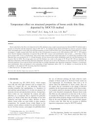
130ARTICLE IN PRESSB.-C. Kang et al. / Journal <strong>of</strong> Physics <strong>and</strong> Chemistry <strong>of</strong> Solids 69 (2008) 128–132Fig. 2. SEM image <strong>of</strong> a TiO 2 <strong>thin</strong> film deposited on the OTS patternedSi(1 0 0) substrate. Inset shows EDX spectra obtained from the selectivelygrown TiO 2 film (A) <strong>and</strong> OTS SAMs surface (B).Fig. 4. Micro-Raman spectra <strong>of</strong> (a) Si(1 0 0) substrate, (b) OTS SAMsarea, <strong>and</strong> (c) TiO 2 deposited area (Raman laser radiation: 514.5 nm,20 mW).Fig. 3. (a) 3D AFM image <strong>of</strong> selective growth <strong>of</strong> TiO 2 <strong>thin</strong> film onSi(1 0 0) surface. (b) 2D AFM image <strong>of</strong> the same film as (a), <strong>and</strong> heightpr<strong>of</strong>ile obtained from the direction <strong>of</strong> black line area.This is a good agreement with reported data <strong>of</strong> selectivegrowth <strong>of</strong> TiO 2 <strong>thin</strong> film with Ti(O i Pr) 2 (tbaoac) 2 [18] <strong>and</strong><strong>of</strong> the CVD grown TiO 2 <strong>thin</strong> <strong>films</strong> with Ti(O i Pr) 4 [20].Fig. 3(a) shows the 3D AFM image <strong>of</strong> the selectivelygrown TiO 2 <strong>thin</strong> film on OTS SAMs patterned Si(1 0 0)substrate at 400 1C. The selective deposition <strong>of</strong> <strong>thin</strong> film<strong>and</strong> the sharp boundary between TiO 2 <strong>thin</strong> film area <strong>and</strong>OTS SAMs area was clearly seen. Fig. 3(b) also shows the2D AFM image obtained from the same film as Fig. 3(a).From the images <strong>of</strong> Fig. 3(a) <strong>and</strong> (b), also we can see twodifferent contrasts similar to SEM images, indicating goodselectivity. With the height pr<strong>of</strong>ile (see inset) <strong>of</strong> the 2DAFM image, we can reconfirm the selective growth <strong>of</strong> TiO 2<strong>thin</strong> film <strong>and</strong> the TiO 2 <strong>thin</strong> film was able to selectivelydeposit on 10 mm area with thickness <strong>of</strong> about 120 nm.The clear <strong>and</strong> convincing evidence <strong>of</strong> selective growthwas obtained by micro-Raman analysis with a 514 nm laser<strong>and</strong> 20 mW power. Fig. 4 shows the micro-Raman spectra<strong>of</strong> the Si(1 0 0) substrate (a), OTS SAMs printed area(b) <strong>and</strong> TiO 2 deposited area (c), respectively. In the case <strong>of</strong>(a) <strong>and</strong> (b), there were no characteristic b<strong>and</strong>s except forthe peaks originated from the Si(1 0 0) substrate. However,in Fig. 4(c), we clearly found that the three b<strong>and</strong>scorresponding to the anatase TiO 2 Raman active fundamentalmodes, are recorded at 144 cm 1 (E g ), 399 cm 1(B 1g ), <strong>and</strong> 639 cm 1 (E g ). The b<strong>and</strong> positions were in very agood agreement with published data on either polycrystallinepowders or monocrystals [21,22]. Moreover, the b<strong>and</strong>sdue to rutile <strong>and</strong> brookite phase <strong>of</strong> TiO 2 were not observed.With these data, we were able to conclude that the anatasephase TiO 2 <strong>thin</strong> film was able to mainly grow on theSi(1 0 0) substrate on which OTS SAMs were not covered,strictly speaking, a native <strong>oxide</strong> layer on Si(1 0 0) surface.This result proved the selectivity <strong>of</strong> TiO 2 <strong>thin</strong> film on theOTS patterned Si(1 0 0) substrate.Selectivity <strong>of</strong> deposited ZrO 2 film can be identified byoptical microscopy (OM) images. Fig. 5 shows an OMimage <strong>of</strong> the deposited ZrO 2 <strong>films</strong> on OTS patternedSi(1 0 0) substrate at 450 1C for 2 h. It shows contrastbetween OTS SAMs area <strong>and</strong> ZrO 2 <strong>thin</strong> <strong>films</strong> depositedregion. The relatively dark area corresponds to the ZrO 2deposited area <strong>and</strong> the bright area is OTS SAMs area.Fig. 6 shows the SEM images <strong>of</strong> selectivity grown onOTS patterned Si(1 0 0) substrate. In the case <strong>of</strong> (a), grownat 450 1C for 2 h, it shows that boundary shape between the