4 Installing OI8 and OIL8 On-Off Input Boards - icemeister.net
4 Installing OI8 and OIL8 On-Off Input Boards - icemeister.net
4 Installing OI8 and OIL8 On-Off Input Boards - icemeister.net

You also want an ePaper? Increase the reach of your titles
YUMPU automatically turns print PDFs into web optimized ePapers that Google loves.
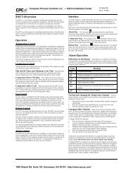
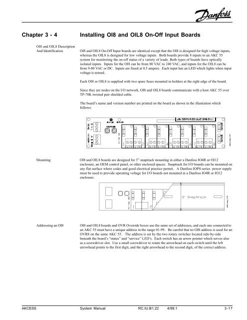
Chapter 3 - 4<strong>OI8</strong> <strong>and</strong> <strong>OIL8</strong> DescriptionAnd Identification<strong>Installing</strong> <strong>OI8</strong> <strong>and</strong> <strong>OIL8</strong> <strong>On</strong>-<strong>Off</strong> <strong>Input</strong> <strong>Boards</strong><strong>OI8</strong> <strong>and</strong> <strong>OIL8</strong> <strong>On</strong>-<strong>Off</strong> <strong>Input</strong> boards are identical except that the <strong>OI8</strong> is designed for high voltage inputs,whereas the <strong>OIL8</strong> is designed for low voltage inputs. Both boards provide 8 inputs to an AKC 55system for monitoring the on-off status of a variety of loads. Both types of boards have opticallyisolated inputs. <strong>Input</strong>s for the <strong>OI8</strong> can be from 80 VAC to 240 VAC, <strong>and</strong> inputs for the <strong>OIL8</strong> can befrom 9-80 VAC or DC. <strong>Input</strong>s are fused at 0.5 ampere. Each input has an LED which lights when inputvoltage is sensed.Each <strong>OI8</strong> or <strong>OIL8</strong> is supplied with two spare fuses mounted in holders at the right edge of the board.Since they are nodes on the I/O <strong>net</strong>work, <strong>OI8</strong> <strong>and</strong> <strong>OIL8</strong> boards communicate with a host AKC 55 overTP-78K twisted pair shielded cable.The board’s name <strong>and</strong> version number are printed on the board as shown in the illustration whichfollows:Mounting<strong>OI8</strong> <strong>and</strong> <strong>OIL8</strong> boards are designed for 3” snaptrack mounting in either a Danfoss IO4R or OI12enclosure, an OEM control panel, or other enclosed spaces. Snaptrack for I/O boards can be mounted onany flat surface where codes <strong>and</strong> good electrical practice permit. A Danfoss IOPS-series power supplymust be used to provide operating voltage for I/O boards not mounted in a Danfoss IO4R or IO12enclosure.Addressing an <strong>OI8</strong><strong>OI8</strong> <strong>and</strong> <strong>OIL8</strong> boards <strong>and</strong> OVR Override boxes use the same set of addresses, <strong>and</strong> each one connected toan AKC 55 must have a unique address in the range 01-99. Be careful that no <strong>OI8</strong> address is used for anOVR8 on the same AKC 55. The address is set by the two rotary switches located side-by-sidebeneath the board’s “status” <strong>and</strong> “service” LED’s. Each switch has an arrow pointer which serves alsoas a screwdriver slot. Use a small screwdriver to rotate the arrowhead on each switch until the leftarrowhead points to the first digit, <strong>and</strong> the right arrowhead to the second digit, of the correct address.AKCESS System Manual RC.IU.B1.22 4/99.1 3-17
<strong>OI8</strong> <strong>and</strong> <strong>OIL8</strong>Power ConnectionsAs with all I/O boards in the AKC 55 system, 12 VAC or 15 VDC from a Danfoss IOPS-series powersupply is connected to a terminal strip labeled “12 VAC” on the <strong>OI8</strong> board. The power terminal strip isshown in the upper left corner of the illustration.Watch the wiring distancefrom the power supply tothe I/O board ! Check thetable in the IOPS-seriesinstruction sheet (it’s inAppendix B) !!Inspection of theInstalled <strong>OI8</strong> or <strong>OIL8</strong>When an <strong>OI8</strong> or <strong>OIL8</strong> <strong>On</strong>-<strong>Off</strong> <strong>Input</strong> Board is ready for operation, you should be able to observe thefollowing, proceeding clockwise around the board from the power terminal strip:1. Power (12 VAC or 15 VDC) has been connected to the “12 VAC” terminal strip.2. The status LED should be blinking. If the status LED is off, there is no power to the board (checkthe fuses). If the status LED is constantly on (not blinking), the board is not communicating withits AKC 55. Make sure the AKC 55 has been configured for this board; if configured, there will beinformation in at least one of the Board <strong>and</strong> Points screens; you can investigate, <strong>and</strong> supplyconfiguration information, if necessary, by following the procedures described in Section IV of thismanual.3. The service LED will normally blink briefly when the <strong>net</strong>work is scanned, but if the service LEDremains steadily on or blinks repeatedly, the RO8 board is defective <strong>and</strong> should be replaced.4. The address switches have been set to a valid address.5. Loads are connected to one or more of the terminal pairs numbered from 1 to 8. When voltage issensed at an input, the LED for the input lights.6. Connection has been made to the I/O <strong>net</strong>work of an AKC 55 at the “NETWORK” terminals.7. If this board is the last node on a run, make sure that it is terminated by using one of the terminatorssupplied with the AKC 55.AKCESS System Manual RC.IU.B1.22 4/99.1 3-19