HUBA604 Mechanical Pressure Switch
HUBA604 Mechanical Pressure Switch
HUBA604 Mechanical Pressure Switch

You also want an ePaper? Increase the reach of your titles
YUMPU automatically turns print PDFs into web optimized ePapers that Google loves.
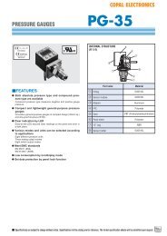
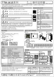
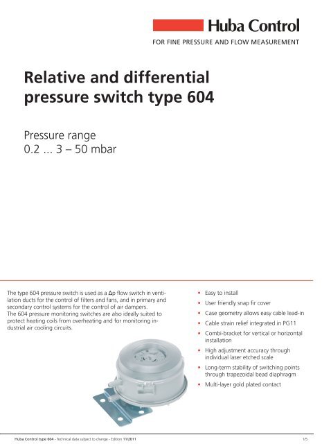
Relative and differentialpressure switch type 604<strong>Pressure</strong> range0.2 ... 3 50 mbarThe type 604 pressure switch is used as a Δp flow switch in ventilationducts for the control of filters and fans, and in primary andsecondary control systems for the control of air dampers.The 604 pressure monitoring switches are also ideally suited toprotect heating coils from overheating and for monitoring industrialair cooling circuits. Easy to install User friendly snap fir cover Case geometry allows easy cable lead-in Cable strain relief integrated in PG11 Combi-bracket for vertical or horizontalinstallation High adjustment accuracy throughindividual laser etched scale Long-term stability of switching pointsthrough trapezoidal bead diaphragm Multi-layer gold plated contactHuba Control type 604 - Technical data subject to change - Edition 11/2011 1/5
Technical overview<strong>Pressure</strong> rangeRelative and differentialOperating conditionsMediumTemperatureTolerable overload on one side0.2 ... 3 50 mbarAir and neutral gasesMedium / ambient-30 ... +85 ÀCStorage-40 ... +85 ÀC-30 ... +75 ÀC 75 mbar-30 ... +85 ÀC 50 mbarMaterials in contact with the mediumSensor Silicon LSR 1)CasePC 10% GFCoverPCElectrical overview<strong>Switch</strong>ing load )5 A at 250 VACResistive load4 A at 30 VDC3)0.8 A at 250 VACInductive0.7 A at 30 VDCContact systemChangeover switchService life mechanical > 10 6 switching cyclesProtection standardWithout cover IP 00With cover IP 54RepeatabilitySetting rangeElectrical connectionScrew terminalsAMP connectors<strong>Pressure</strong> connectionsPipeInside threadInstallation arrangementRecommendation (Factory set)0.2 ... 3 mbarμ 0.025 mbar0.5 ... 5 mbar μ 0.05 mbar1 ... 10 mbar betweenμ 0.05 mbar5 ... 20 mbar μ 0.05 mbar10 ... 50 mbar μ 0.15 mbar6.3 mm4.8 mm± 6.2 mmG ⅛Vertical, pressure connections facing downwardsHorizontal, cover facing downwards <strong>Switch</strong>ing points approx. 11 Pa lower than on scaleHorizontal, cover facing upwards <strong>Switch</strong>ing points approx. 11 Pa higher than on sclaeTests / AdmissionsDVGW acc. to DIN 1854Electromagnetic compatibility CE conformity acc. to EN 61326-2-3EU conformityLow voltage directive 73/23/EWGGas appliance directive90/396/EWG CE 0085 A P0918WeightWithout bracketWith combi-bracket type CPackaging (Please state on order)Single packaging in cardboardMultiple packaging in cardboard~ 93 g~ 143 g20 pcs100 pcs320 pcsSetting ranges0.2 ⁄ 3 mbar4)0.5 ⁄ 5 mbar4)1 ⁄ 10 mbar4)5 ⁄ 20 mbar4)10 ⁄ 50 mbar4)Upper switching point (mbar)<strong>Switch</strong>ing difference (mbar)5)<strong>Switch</strong>ing difference (mbar)5)<strong>Switch</strong>ing difference (mbar)5)<strong>Switch</strong>ing difference (mbar)5)<strong>Switch</strong>ing difference (mbar)5)1)at 200 ÀC tempered, free of gas emissions2)Multi-layer contact (suitable for DDC)3)6-fold starting current cos φ 0.6)4)Tolerance switching difference5)Factory-setting2/5Huba Control type 604 - Technical data subject to change - Edition 11/2011
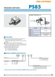
Compact A/C set (standard) Setting range (mbar) Connection set Order numberConsisting of switch with hose connection ± 6.2 mm, scale in mbar, screwterminals, multi-layer contact up to 5 A (suitable for DDC), combi-brackettype C and hose connection set, single packaging.0.2 ⁄ 3 mbar Fig. 1 (Metal) 604.90000010.5 ⁄ 5 mbar Fig. 1 (Metal) 604.91000011 ⁄ 10 mbar Fig. 1 (Metal) 604.92000010.2 ⁄ 3 mbar Fig. 2 (Plastic) 604.90000020.5 ⁄ 5 mbar Fig. 2 (Plastic) 604.91000021 ⁄ 10 mbar Fig. 2 (Plastic) 604.920000210 ⁄ 50 mbar Fig. 2 (Plastic) 604.9500002Order code selection tableVersion Standard version 9ETL versionESetting range 0.2 ⁄ 3 mbar 20 ⁄ 300 Pa 0.08 ⁄ 1.2 inH2O 0.08 ... 1.2 inWC 00.5 ⁄ 5 mbar 50 ⁄ 500 Pa 0.2 ⁄ 2 inH2O 0.2 ... 2 inWC 11 ⁄ 10 mbar 100 ⁄ 1000 Pa 0.4 ⁄ 4 inH2O 0.4 ... 4 inWC 25 ⁄ 20 mbar 500 ⁄ 2000 Pa 2 ⁄ 8 inH2O 2 ... 8 inWC 410 ⁄ 50 mbar 1000 ⁄ 5000 Pa 4 ⁄ 20 inH2O 4 ... 20 inWC 5Scale Scala in mbar 0Scala in Pa 1Scala in inH2O 2Scala in inWC 6Without Scala (ratting plate in mbar) 3Without Scala (ratting plate in Pa) 4Without Scala (ratting plate in inH2O) 5Without Scala (ratting plate in inWC) 7<strong>Pressure</strong> connections Pipe ± 6.2 mm without pressure tip orifice 0Pipe ± 6.2 mm with pressure tip orifice on P2 1Inside thread G ⅛ without pressure tip orifice 2Inside thread G ⅛ with pressure tip orifice on P2 3Electronical connection Screw terminals 0AMP connector 6.3 mm 1AMP connector 4.8 mm 2Cover / Bracket With cover combi bracket type C IP 54 0With cover bracket type A IP 54 1With cover bracket type B IP 54 2With cover without bracket IP 54 3Without cover combi bracket type C 5Without cover bracket type A 6Without cover bracket type B 7Without cover without bracket 8Connection kit Without 0With connection set (metal), 90À angled incl. tube 2 m long (Fig. 1) 1With connection set (plastic), straight incl. tube 2 m long (Fig. 2) 2<strong>Switch</strong>ing points Two factory set switching points (please specify on order) WOne factory set switching point high (please specify on order) ROne factory set switching point low (please specify on order) UAccessoriesOrder numberConnection kit for vent duct (metal), 90À angled including tube 2 m long (Fig. 1) 104312Connection kit for vent duct (plastic), straight including tube 2 m long (Fig. 2) 100064Bracket type A 100295Bracket type B 100098Combi-bracket type C 100106Attachment ring 110005Attachment ring close 110006Special screws for fastening bracket to switch (2 screws per switch required) 102976Fastening clip for bracket A, B, C or direct mounting for wall thickness 0.8 ⁄ 1.1 mm 100294for wall thickness 1.8 ⁄ 2.1 mm 100293Calibration certificate 104551604. X X X X X X X XAccessories supplied looseHuba Control type 604 - Technical data subject to change - Edition 11/2011 3/5
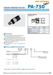
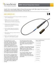
Dimensions in mm / Electrical connections11 Zuleitung Feeder (COM)22 Ruhekontakt NC contact (NC)33 Arbeitskontakt NO Contact (NO)1)Hole for PT screws KA25AccessoriesBracket type A Bracket type B Combi-bracket type CWinkel Typ A Winkel Typ B Kombi-Winkel Typ CFig. 1StrömungsraumFlow area± D ± = D 5.1 = 5.1 + +0.1 0.1 Löcher Holes für for Schnappring fastening clipFig. 2Flow areaStrömungsraumFastening clip (mounted) Attachment ring close (mounted) Attachment ring (mounted)Schnappring (in montiertem Zustand)Befestigungsring geschlossenBefestigungsring4 x hole PT - screw d1 = 3.0 mm 4 x hole PT - screw d1 = 3.0 mm4/5Huba Control type 604 - Technical data subject to change - Edition 11/2011