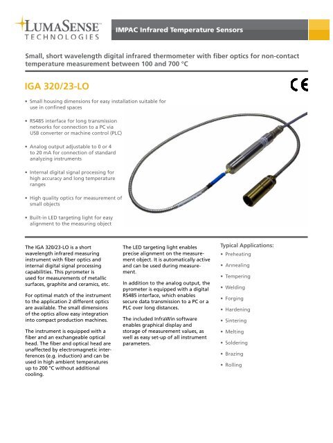
IGA 320/23-LO
IGA 320/23-LO
IGA 320/23-LO

Create successful ePaper yourself
Turn your PDF publications into a flip-book with our unique Google optimized e-Paper software.
Technical DataMeasurement SpecificationsTemperature Range: 100 to 700 °C (MB 7)CommunicationAnalog Output:0 to 20 mA or 4 to 20 mA (linear), switchableSub Range:Spectral Range:IR Detector:Resolution:Emissivity ε:Transmittance τ:Measurement Uncertainty:(ε = 1, t 90 = 1 s, T amb. = <strong>23</strong> °C)Note: the pyrometer must operateat least 30 min before thesevalues are validRepeatability:(ε = 1, t 90 = 1 s, T amb. = <strong>23</strong> °C)InterfaceConnection:Any range adjustable within the temperaturerange, minimum span 51 °C2 to 2.6 μm (main wavelength 2.3 μm)Extended InGaAs0.1 °C on interface; < 0.025% of the adjustedtemperature sub range at the analog output10.0 to 100.0%, adjustable via interface insteps of 0.1%10.0 to 100.0%, adjustable via interface insteps of 0.1%Up to 400 °C: 2 °Cabove 400 °C: 0.3% of measured value in °C+ 1 °CNote: The temperature of fiber and optical headmust be at least 30 °C lower than the measuringtemperature to get a correct temperature reading0.1% of measured value in °C + 1 °CNote: The temperature of fiber and optical headmust be at least 30 °C lower than the measuringtemperature to get a correct temperature reading8 pin connectorOptics:Optical head Type I or Type II (short distancesonly, see table); fiber Ø 0.4 mm (blue fibermark); DIN connector electronics side andSMA connector optics sideSighting:Built-in LED targeting light(default continuously on)Parameters: Adjustable via interface: Emissivity ε,transmittance t, exposure time t 90 ,max./min. value storage, analog output, subtemperature range, ambient temperaturecompensation, pyrometer address, switchcontact, hysteresis, baud rate, wait time t W,targeting lightDigital Interface:Exposure Time t 90 :Maximum Value Storage:ElectricalPower Supply:Power Consumption:RS485 addressable (half duplex), baud rate1200 up to 38400 Bd2 ms (with dynamic adaptation at low signallevels); adjustable to 0.01 s; 0.05 s; 0.25 s;1 s; 3 s; 10 sBuilt-in single or double storage. Clearingwith adjusted time t clear (off; 0.01 s;0.05 s; 0.25 s; 1 s; 5 s; 25 s), via interface orautomatically with the next measuring object24 V DC (10 to 30 V DC), ripple must be lessthan 0.5 VMax. 1 WSwitch Contact: Opto relays; max. 50 V DC, 0.2 A;Pmax = 300 mWHystersis: 2 to 20 °CLoad (analog output):0 to 500 ΩIsolation:Power supply, analog output and digitalinterface are galvanically isolated from eachotherEnvironmental SpecificationsProtection Class: IP 65 (IEC 60529)Operating Position:anyAmbient Temperature: 0 to 70 °C at housing; up to 200 °C on sideof fiber and optical headStorage Temperature: -20 to 70 °CRelative Humidity:Weight:Non condensing conditions0.53 kg incl. optical fiber and lens assemblyHousing:Stainless steelCE Label: According to EN 61326-1:2006-10Dimensions<strong>IGA</strong> <strong>320</strong>/<strong>23</strong>-<strong>LO</strong>Optical head Type I (fixed adjusted)Optical head Type II (focusable)Optical head Type II (fixed adjusted)All dimensions in mm
OpticsDepending on the application, the instrument will be delivered with a small or a large optical head. The selection of the optical head depends not only on its size but also onthe required spot size (size of the measuring object) and the measuring distance. Distance ”a” is specified from the front of the lens.Optical head Type I (fixed adjusted):With the very small dimensions the optical head Type I is suited for use in confined spaces. The optics is adjusted ex works to one of the measuring distances mentioned in thetable below. The mentioned spot size will be achieved in exactly this distance, however other distances can be realized on request.Optical head Type II (focusable):The optical head Type II is focusable, i.e. each measuring distance can be adjusted within the mentioned limits to achieve the smallest spot size in the required distance. Thespot size at the shortest and longest distance is mentioned in the table below. Spot sizes at intermediate distances have to be calculated by interpolation.Optical head Type II (fixed adjusted):The fixed adjusted optical head Type II has a similar size as the focusable optical head Type II, but offers a fixed focusing distance like optical head Type I. The mentioned spotsize will be achieved in exactly this distance, however other distances can be realized on request.OpticsOptical head Type I(fixed adjusted:Optical head Type II(focusable):Optical head Type II(fixed adjusted):Ref. Number(Replacement Optics)Measuring Distance a [mm] Spot size M90 [mm] Aperture D [mm]3 873 <strong>320</strong> Adjusted to: 120 2.3 73 873 340 Adjusted to: 260 5.5 73 838 210 Range: 88 to 110 0.8 to 1.2 17.5 to 15.53 838 220 Range: 95 to 129 1.0 to 1.4 16.5 to 14.53 838 <strong>23</strong>0 Range: 105 to 161 1.1 to 1.8 15 to 13.53 838 240 Range: 200 to 346 1.9 to 3.4 17.5 to 15.53 873 420 Adjusted to: 87 0.8 153 873 440 Adjusted to: 200 1.9 15Optional Lightpipe Optics:The <strong>IGA</strong> <strong>320</strong>/<strong>23</strong>-<strong>LO</strong> can also use a sapphire optical rod (so called “lightpipe”) as the optics to collect the infrared radiation from the target.Lightpipes can be inserted through small holes or vacuum fittings and can survive harsh temperature and pressure environments as well asstrong RF fields. This configuration is ideal for applications using induction heating or when there is not optical access for a traditional lenssolution to have sufficient viewing access to the target. Versions with lightpipe optics are available as a special on request.Equipment FeaturesRobust stainless steel housing with small dimensionsMonofiber instainless steel, flexibleprotection tubeConnection cable with connector and cables for:• Power supply• LED targeting light switch on/off• RS485 interface• Analog output• Switch contactLED targeting light shows middle of spot size and optics focusPrecision opticsSettings and Operation via the RS485 Interface and InfraWinOnce connected, the signal processing can be done via the analog output (e.g. for connection of a digital display) or via thedigital RS485 interface (for connection of a PC or to a PLC). With RS485, long transmission distances can be realized andseveral pyrometers can be connected in a bus system. The included InfraWin software enables easy instrument settings andprovides multiple temperature illustration views.InfraWin software enables:• Easy instrument settings• Display of temperature curves• Graphic or tabular analysis, e.g. for printing out or exporting• Quick spot size calculation
Reference NumbersTemperature Range Fiber Length 2.5 m Fiber Length 1 m100 to 700 °C (MB 7) 3 903 970 3 903 980Scope of delivery: Pyrometer with PC adjustment and evaluation software“InfraWin”, works certificate, manual, optical fiber, one selectable optical headOrdering note: A connection cable is not included in scope of delivery and must beordered separatelyAccessories3 826 510 PI 6000: PID programmable controller, extremely fast, for digitalIMPAC pyrometers3 826 520 PI 6000-N: PID programmable controller, extremely fast, forpyrometers with analog output3 834 <strong>23</strong>0 Adjustable mounting support, stainless steel3 834 370 Mounting support for optical head I (fixed)3 834 380 Mounting support for optical head I (adjustable)3 834 050 Ball and socket mounting with clamp for optical head I or II or airpurge unit for optical head II3 834 <strong>23</strong>0 Adjustable mounting support for optical head II3 835 170 Air purge unit for optical head I3 835 180 Air purge unit for optical head II3 835 240 90° mirror (with air purge)3 835 290 Air purge for scanner3 835 500 Air purge unit with ceramic tube (small) for optical head I3 835 510 Air purge unit with ceramic tube (large) for optical head I3 843 460 SCA 300, scanning attachment with quartz glass window;24 V AC/DC3 846 170 Mounting tube (L 600 x Ø 70 mm)3 852 290 Power supply NG DC, 100 to 240 V AC, 50 to 60 Hz to 24 V DC, 1 A3 852 550 Power supply NG 2D, 85 to 265 V AC, 48 to 62 Hz to 24 V DC, 600mA, with 2 limit switches3 852 580 RS<strong>23</strong>2 to USB converter (matched to DA 6000-T)3 852 600 USB nano: Converter RS485 to USB3 852 610 USB LabKit, adapter RS485 to USB with targeting light push-buttonand analog output clamp, pyrometer cable, power supply100 to 240 V AC3 890 150 DA 6000-T, digital display for measurement of the cooling-off timefrom 800 to 500 °C (for welding processes), RS<strong>23</strong>2 interface3 890 530 DA 6000, LED-display, RS485, max. value storage, analog output3 890 640 DA 4000-N, LED-display, 2-wire power supply(specify <strong>23</strong>0 or 115 V AC)3 890 650 DA 4000, LED-display, 2-wire power supply, 2 limit switches (relaycontacts) (specify <strong>23</strong>0 or 115 V AC)3 920 030 Connection cable, 2 m (straight connector)3 920 040 Connection cable, 5 m (straight connector)3 920 050 Connection cable, 10 m (straight connector)3 920 060 Connection cable, 15 m (straight connector)3 920 070 Connection cable, 20 m (straight connector)3 920 080 Connection cable, 25 m (straight connector)3 920 090 Connection cable, 30 m (straight connector)3 920 130 Connection cable, 2 m (90° connector)3 920 140 Connection cable, 5 m (90° connector)3 920 150 Connection cable, 10 m (90° connector)3 920 160 Connection cable, 15 m (90° connector)3 920 170 Connection cable, 20 m (90° connector)3 920 180 Connection cable, 25 m (90° connector)3 920 190 Connection cable, 30 m (90° connector)3 920 100 Adapter cable (0.2 m) 8 pin onto 12-pin IMPAC standard connectorAccessory OverviewMechanical OverviewElectrical OverviewScanning AttachmentSCA 300Air Purge for ScanningAttachmentLED Digital DisplayDA 6000NG 2DPower SuppliesNG DCMounting TubeAir Purge90° Mirror(with Air Purge)USB-LabKitConverter RS485 to USB