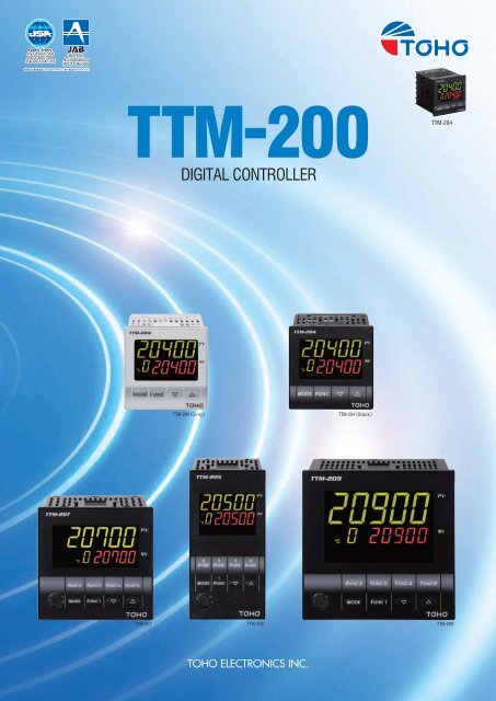
TTM-200 Digital Controller
TTM-200 Digital Controller
TTM-200 Digital Controller

Create successful ePaper yourself
Turn your PDF publications into a flip-book with our unique Google optimized e-Paper software.
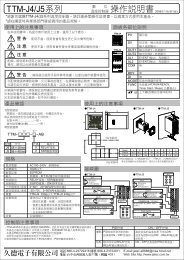
■Dimensions<strong>TTM</strong>-204PVTIMEFCOUT1 OUT2 OUT3 OUT4 RDY COM DI1 DI2 TMRSVMODE FUNCTOHOModel a b c d A B C D L<strong>TTM</strong>-204 45 +0.6−0<strong>TTM</strong>-205 92 +0.6−0<strong>TTM</strong>-207 68 +0.6−0<strong>TTM</strong>-209 92 +0.6−045 +0.6−045 +0.6−068 +0.6−092 +0.6−060 48 48 48 2 55 (Bxn−3) +0.6−0120 48 96 48 2 65 (Bxn−3)+1−090 72 72 72 2 65 (Bxn−3) +1−0120 96 96 96 2 65 (Bxn−3)+1−0■Panel Installation<strong>TTM</strong>-204<strong>TTM</strong>-205、207、209*For this panel installation, please be careful sufficiently to avoid any of damage.
■Advanced Features●PID control by new algorithm●Timer function1. In the case of bread baking oven●Put dough in the oven, and push the start key to the timer.●The temperature is controlled by the heater and so on for the timer setup time.●After timer count end control is stopped automatically(It is used when making control STOP after the timer count ends.) ●BLIND Function Setting2. In case of packing machine and industrial machine, which control is started after thecompleting the preparation of the peripheral device●The count of the timer begins from point that turns on the power supply.●The control output stops during timer setting time●The control starts automatically after the timer count ends.(It is used when making control starts after the timer count ends.) ●Communication function◦A connection example with the personal computerCentralized supervision with the personal computer is possible with the connection likethe chart below.Content of the above ★1) In BLIND MODE, either 「ON」& 「OFF] is displayed on under each characters (SV display).「ON」is displayed. 「OFF」is not displayed (BLIND).2) To change characters in BLIND MODE by pressing 「FUNC」key.3) Power OFF for end of BLIND setting mode.It is possible not to make the optional picture indicate by the key operation◦Loader communicationIn addition, please note that only measured value is displayed without displaying asetting value in the case of the usual display when the SV setup screen is turned off.●OFF point position movement of ON/OFF controlWhen the OFF point position movement is set to 0, the OFF point is the set value position. ※Loader cable specification[Appearance and structure][Standard and performance]USB I/F standardUSB Specification 2.0 ConformingDTE (Personal computer side) speed Up to 38400bpsThis is when off point position movement is set up with (+5).Actually specification, there is no description change as above, but move above equal to(+5) as a position of ON/OFF.Case it made move on negative side, the OFF point moves to opposite side to descriptionabove.Connector specification[Model]<strong>TTM</strong>-LOADERPersonal computer side: USBTemperature <strong>Controller</strong> side:φ2.5mm Stereo plug
■Ordering Information (Model Configurations) 1 Model 4 48×485 96×487 72×729 96×962 Case color Q BlackX Gray (Only selected with 204)3 Output 1 N No J Voltage 0 to 5VDCR Relay point of contact F Voltage 1 to 5VDCP Voltage for SSR driving G Voltage 0 to 10VDCA Open collector I Current 4 to 20mADCK Voltage 0 to 1VDC H Voltage 0 to 10mVDC4 Output 2 N No J Voltage 0 to 5VDCR Relay point of contact F Voltage 1 to 5VDCP Voltage for SSR driving G Voltage 0 to 10VDCA Open collector I Current 4 to 20mADCK Voltage 0 to 1VDC H Voltage 0 to 10mVDC5 Output 3、4 A Open collectorR Relay point of contactSame for the remote controllers on all models6 Output 5、6 A Open collector Not selectable for 204R Relay point of contact 207 cannot select output 67 Output 7 A Open collector Not selectable for 204R Relay point of contact Not selectable when W (event 3) has been by 2078 AI input Y Remote SV input (voltage/current only) Not selectable for TTV-2049 Option 204 Selection ST CT1, 2SV CT1, event 2UV Event 1, 2207 Selection ST CT1, 2SV CT1, event 2UV Event 1, 2STW CT1, 2 event 3 (output 7 not selectable)SVW CT1, event 2, 3 (output 7 not selectable)UVW Event 1, 2, 3 (output 7 not selectable)205, 209 Selection ST CT1, 2SV CT1, event 2UV Event 1, 2SVW CT1, event 2, 3, 4UVW Event 1, 2, 3, 4STUV CT1, 2 event 1, 2STUVW CT1, 2 event 1, 2, 3, 410 Communication M Communications (RS-485)11 Power Supply 100 to 240V (free power)L 24VAC/DC*Parameters up to output 2 must be selected.*Specifications apply in accordance with the sequence of selection for output 3 and upwards.Example: <strong>TTM</strong>-209-Q-PR-RUVWP: Output 1: SSR drive voltageR: Output 2: Relay connectionR: Output 3, 4: Relay connection (does not select output 5 and 6)UVW: EV1, 2, 3, 4*Output 3 and 4 must be selected when output 5 and 6 are required.*Output 3 and 4 and output 5 and 6 must be selected when output 7 is required.*Option W only consists of event 3 when <strong>TTM</strong>-207 has been selected.*CTL-6-P-H is added when CT is selected. (2 are added when 2 CTs are selected.)*CT cannot be selected when only analog has been selected for the output.