
Create successful ePaper yourself
Turn your PDF publications into a flip-book with our unique Google optimized e-Paper software.
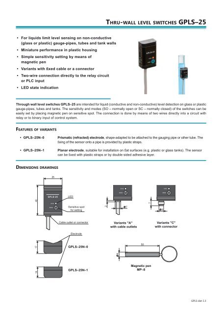
TECHNICAL SPECIFICATIONSSupply voltage 6 ... 30 V DCSupply current - OFF stateSwitched current (min / max)Max. 0.6 mA3.3 mA / 40 mARemanent voltage – ON stateMax. 6 VMax. thickness of the vessel wall– Conductive liquids8 mm– Non-conductive liquids with Ɛ r< 10*3 mmAmbient temperature range-20 ... +80°CTemperature range at the tube or vessel surface / with double-side self adhesive tape -20 ... +90°C / +60°CHousing materialPlastic (PP)Protection classIP67Connection cable type (Variants "A") PVC 2 x 0.34 mm 2Weight (including 2 m cable)Approx. 60 g*) Ɛ rsee "Table of dielectric constants"ELECTRICAL CONNECTIONPositive pole (+ U) of power supply is connected through a load (relay) to brown wire or pin connector No. 1, negative pole (0V)is connected to white wire or pin connector No. 3. The sensor output is protected against short circuits. Capacity loads and loadswith low sleep resistance (bulb) the sensor evaluates as a short circuit.Note: In case of high ambient electromagnetic interference,parallel conductors with power lines, or lines at distancesgreater than 30 m, we recommend to use shielded cable.Legend:(1), (3) – Terminals number for variants with connectorBN – BrownWH – WhiteINSTALLATION AND RECOMMENDATIONSPlastic strapsPoint level detection on plasticor glass gauge pipes andtubes. The sensor is fi xedto the gauge pipe or tube bymeans of two plastic straps(2.5 mm width). The cableshould be vertically downwardsoriented. The maximum wallthickness of the tube dependson the detected medium (seetechnical data); the maximumis 8 mm.Applies to:<strong>GPLS</strong>–<strong>25</strong>N–0<strong>Thru</strong>-wall level sensing of liquidsin plastic or glass vesselswith flat walls. The sensor is installedon a clean and degreasedsurface of the vessel wall. Theattachment is done by doublesidedadhesive layer. Orientationof the sensor can be arbitrary.Maximum thickness of the vesselwall depends on the detectedmedium (see technical data); themaximum is 8 mm.Applies to:<strong>GPLS</strong>–<strong>25</strong>N–1SENSOR SETTINGSThe setting is done by placing magnetic pen MP–8 to sensitive spot M located on thefront of the sensor. Short time attaching (up to 2 s) of the magnetic pen to the sensitivespot M makes the sensor open, attaching for a longer time (at least 4 s) the sensorcloses. In this way is set the sensitivity for the measured medium and switching modesSO (normally open) or SC (normally closed). When changing the fl uid it is necessary tomake the new setting.Sensitive spot<strong>GPLS</strong>-dat-2.3
STATUS SIGNALIZATIONIndicatorOrange LEDFunctionContinuous light – Sensor is closed (switched ON)Dark – Sensor is open (switched OFF)Rapid flashing (period 0.2 sec.) * – Unrecognized upper and lower limits or setting mistakeSlow flashing (period 0.8 sec.) – Short circuit at sensor output* Sensor for each flash of the LED switches its output on for approx. 3 ms. This period is sufficiently short to avoid unwantedswitching of relay contacts. For binary inputs, we recommend to set the filter so as not to respond to pulses shorter than 3 ms.ORDER CODE<strong>GPLS</strong> – <strong>25</strong> – –– SCableLength of cable in meters (variant "A")Type of output:A – Cable outlet (+ Spec. the length of the cable)C – Connector (+ Spec. type of the socket)Performance:N – Normal(for non-explosive areas)Electrode type:0 – Prismatic (refracted)1 – PlanarCORRECT SPECIFICATION EXAMPLES<strong>GPLS</strong> – <strong>25</strong>N – 0 – A–S Cable 5 m<strong>GPLS</strong> – <strong>25</strong>N – 1 – C – S + Type of the connectorACCESSORIESStandard – included in the level sensors price• 2 pcs of Plastic straps 2.5 x 200 mm• 1 pc of Double-side self adhesive tape (<strong>GPLS</strong>–<strong>25</strong>N–1)• 1 pc of Magnetic pen MP–8Optional – for extra charge• Connector ELKA KV 3308SAFETY, PROTECTIONS AND COMPATIBILITYThe level sensor is equipped with a protection against electric shock on electrode, polarity, overvoltage and short-term currentoverload on the output.Electromagnetic compatibility is provided by conformity with standards EN 55022 / B, EN 61326-1, EN 61000-4-2 ,-3, -4 and -6.Version 10/2011