Visiplex Technician System Installation Overview.pdf
Visiplex Technician System Installation Overview.pdf
Visiplex Technician System Installation Overview.pdf

Create successful ePaper yourself
Turn your PDF publications into a flip-book with our unique Google optimized e-Paper software.
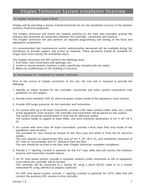
<strong>Visiplex</strong> <strong>Technician</strong> <strong>System</strong> <strong>Installation</strong> <strong>Overview</strong>1. <strong>Visiplex</strong> <strong>Technician</strong> Scope of Work<strong>Visiplex</strong> will be providing a factory-trained technician for on-site installation services of the wirelesssystem’s fixed end equipment.The <strong>Visiplex</strong> technician will mount the outdoor antenna on the mast pole provided, ground theantenna and terminate all connections between the controller, transmitter and antenna.The <strong>Visiplex</strong> technician will also perform all required programming and testing of the fixed endequipment components.It’s recommended that maintenance and/or administrative personnel will be available during theinstallation to provide support and access as required. These personnel should be available forlonger work hours during the installation day/s.The <strong>Visiplex</strong> technician will NOT perform the following tasks:1. Drill holes, seal connections and openings, etc.2. Install or mount wireless receivers (unless specifically included with the order).3. Make any modifications to the building or structure.2. Prerequisites for <strong>Installation</strong> by <strong>Visiplex</strong> <strong>Technician</strong>Prior to the arrival of <strong>Visiplex</strong> technician to the site, the end user is required to provide thefollowing:1. Identify an indoor location for the controller, transmitter and other system components (seeguidelines on next pages).2. Provide three standard 120V AC electrical power outlets inside of the equipment room location.3. Provide UPS/surge protector for the controller and transmitter.4. For system with up to 40 watts transmitter, provide a flat clean surface (shelf, desk, etc.) insideof the equipment room location. The controller and transmitter will be placed on this surface.The surface should be located within 4’ from the AC electrical outlets.The surface needs to support at least 50lbs, and have minimum dimensions of 24” X 20” (W XD).5. For system with more than 40 watts transmitter, provide a level clean floor area inside of theequipment room location.The provided 19” rack should be located on this floor area and within 4’ from the AC electricaloutlets.The rack requires an approximate floor area of 24” X 24” (W X D), and installation clearance of24” from its surroundings and 72” clearance from the floor.The rack should be secured to the floor after <strong>Visiplex</strong> technician completes installation.6. Provide a 1” opening (conduit is optional) for the 0.5” coax cable that will connect the outdoorsantenna and transmitter located indoors.7. For PC time based system, provide a computer network (LAN) connection to the to equipmentroom where the controller will be located.The controller will be connected to a nearby PC using a direct RS232 cable or to a remotenetworked PC using LAN-RS232 adaptor (optional).For GPS time based system, provide 1” opening (conduit is optional) for CAT5 cable that willconnect the outdoors GPS receiver to the controller.Version 1.0 1
For all other systems, it’s recommended that computer network (LAN) connection will beprovided to the equipment room.8. Run the coax cable and CAT5 cable (if provided) from the outside in to the equipment room.9. Provide 1.5” to 2” mast pole that is side wall-mounted and is at least two feet above theroofline. The mast pole will be used to install the outdoor fiberglass antenna (<strong>Visiplex</strong> willprovide all required mounting hardware to attach the antenna to the mast pole).3. <strong>System</strong> LocationConsider the following requirements when planning system installation and choosing a location forthe controller and other system components:1. The transmitting antenna should be located as high as possible and as close as possible to thecenter of the site. The antenna should not be surrounded by large metal objects that may blockthe RF signal and decrease the coverage.2. Locate a path for running the coax cable between the antenna and the transmitter such as ariser (if there is no existing path, create one).3. For systems with outdoors antenna, the transmitter should be placed as close as possible to theroof or the antenna location. Keep the distance between the antenna and the transmitter asshort as possible to minimize RF power loss.4. Choose a location that is easily accessible in case you need to perform maintenance on the antenna.4. Magnetic Mount Antenna Location1. The antenna will require an adequate grounding surface, such as metal surface, HVAC duct or metal“I” beam.2. Choose a location that will provide free space for RF radiation. If the antenna is mounted too close tometal or closed in heavy concrete walls room, a high VSWR may occur which may cause damage tothe transmitter.3. The optional wall-mount “L” bracket allows mounting the magnetic antenna on the side of a buildingor other structure, providing the roof’s overhang is not excessive.5. Base Station Outdoors Antenna Location1. Choose a location that is not obstructed by trees, branches, power-lines, etc.2. Choose a location that will provide free space for RF radiation. If the antenna is mounted too close tometal or closed in heavy concrete walls room, a high VSWR may occur which may cause damage tothe transmitter.3. Make sure the antenna is installed at an elevation that will provide sufficient clearance to allow theantenna to radiate without interference.4. The antenna should be secured to a well-grounded metal structure or to a pole on the roof.5. It is recommended to mount the antenna where the path of the antenna cable is straight and asclose as possible to the system transmitter.Version 1.0 2
6. <strong>Installation</strong> DiagramsMagnetic Mount AntennaCoaxial Cable (BNC to BNC)Encoder / Controller RF OutputLow Power <strong>System</strong> <strong>Installation</strong> DiagramMagnetic Mount Antenna(Optional Base Antenna)Coaxial Cable (BNC to BNC)External TransmitterData Cable(DB25M – DB15M)Encoder / Controller Transmitter OutputMedium Power <strong>System</strong> <strong>Installation</strong> DiagramVersion 1.0 3
AC VoltageDC VoltageCOAX CableData CableAntennaAC PowerDATA I/O 12V DCRFOutDB25AC-DC+DCRFInRFOut+DC-DCACEncoder /ControllerTransmitterPowerAmplifierPowerSupplyHigh Power <strong>System</strong> <strong>Installation</strong> DiagramVersion 1.0 4