VNS2210 Programming Guide - Visiplex
VNS2210 Programming Guide - Visiplex
VNS2210 Programming Guide - Visiplex

Create successful ePaper yourself
Turn your PDF publications into a flip-book with our unique Google optimized e-Paper software.
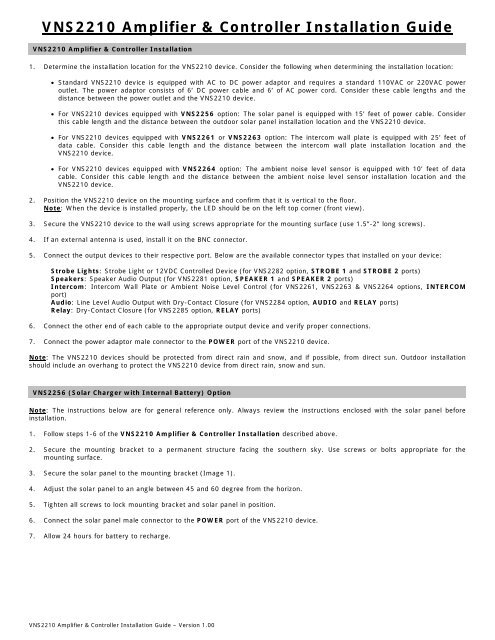
<strong>VNS2210</strong> Amplifier & Controller Installation <strong>Guide</strong><strong>VNS2210</strong> Amplifier & Controller Installation1. Determine the installation location for the <strong>VNS2210</strong> device. Consider the following when determining the installation location: Standard <strong>VNS2210</strong> device is equipped with AC to DC power adaptor and requires a standard 110VAC or 220VAC poweroutlet. The power adaptor consists of 6’ DC power cable and 6’ of AC power cord. Consider these cable lengths and thedistance between the power outlet and the <strong>VNS2210</strong> device. For <strong>VNS2210</strong> devices equipped with VNS2256 option: The solar panel is equipped with 15’ feet of power cable. Considerthis cable length and the distance between the outdoor solar panel installation location and the <strong>VNS2210</strong> device. For <strong>VNS2210</strong> devices equipped with VNS2261 or VNS2263 option: The intercom wall plate is equipped with 25’ feet ofdata cable. Consider this cable length and the distance between the intercom wall plate installation location and the<strong>VNS2210</strong> device. For <strong>VNS2210</strong> devices equipped with VNS2264 option: The ambient noise level sensor is equipped with 10’ feet of datacable. Consider this cable length and the distance between the ambient noise level sensor installation location and the<strong>VNS2210</strong> device.2. Position the <strong>VNS2210</strong> device on the mounting surface and confirm that it is vertical to the floor.Note: When the device is installed properly, the LED should be on the left top corner (front view).3. Secure the <strong>VNS2210</strong> device to the wall using screws appropriate for the mounting surface (use 1.5”-2” long screws).4. If an external antenna is used, install it on the BNC connector.5. Connect the output devices to their respective port. Below are the available connector types that installed on your device:Strobe Lights: Strobe Light or 12VDC Controlled Device (for VNS2282 option, STROBE 1 and STROBE 2 ports)Speakers: Speaker Audio Output (for VNS2281 option, SPEAKER 1 and SPEAKER 2 ports)Intercom: Intercom Wall Plate or Ambient Noise Level Control (for VNS2261, VNS2263 & VNS2264 options, INTERCOMport)Audio: Line Level Audio Output with Dry-Contact Closure (for VNS2284 option, AUDIO and RELAY ports)Relay: Dry-Contact Closure (for VNS2285 option, RELAY ports)6. Connect the other end of each cable to the appropriate output device and verify proper connections.7. Connect the power adaptor male connector to the POWER port of the <strong>VNS2210</strong> device.Note: The <strong>VNS2210</strong> devices should be protected from direct rain and snow, and if possible, from direct sun. Outdoor installationshould include an overhang to protect the <strong>VNS2210</strong> device from direct rain, snow and sun.VNS2256 (Solar Charger with Internal Battery) OptionNote: The instructions below are for general reference only. Always review the instructions enclosed with the solar panel beforeinstallation.1. Follow steps 1-6 of the <strong>VNS2210</strong> Amplifier & Controller Installation described above.2. Secure the mounting bracket to a permanent structure facing the southern sky. Use screws or bolts appropriate for themounting surface.3. Secure the solar panel to the mounting bracket (Image 1).4. Adjust the solar panel to an angle between 45 and 60 degree from the horizon.5. Tighten all screws to lock mounting bracket and solar panel in position.6. Connect the solar panel male connector to the POWER port of the <strong>VNS2210</strong> device.7. Allow 24 hours for battery to recharge.<strong>VNS2210</strong> Amplifier & Controller Installation <strong>Guide</strong> – Version 1.00
Image 1VNS2261 & VNS2263 (2-Way Intercom) OptionNote: The instructions below are for general reference only. Always review the instructions enclosed with intercom wall plate beforeinstallation.1. Before installation, consider the distance between the <strong>VNS2210</strong> device and the VNS2261 or VNS2263 intercom wall plate. The<strong>VNS2210</strong> device and the intercom wall plate will be connected using the provided CAT5 cable (25’ long).2. Follow steps 1-6 of the <strong>VNS2210</strong> Amplifier & Controller Installation described above.3. Disconnect the power source connector from the POWER port of the <strong>VNS2210</strong> device.4. Run the data cable between the <strong>VNS2210</strong> device and the intercom wall plate (Image 2).5. Connect the RJ45 end of the cable to the intercom wall plate.6. Install the intercom wall plate according to the instructions provided with it. Attach the intercom wall plate to a single gang boxusing the supplied 2 screws (Image 3).Note: When mounting directly to wall surface (without gang box), remove the data cable outlet from the bottom and pass thecable through the outlet at the bottom.7. Connect the other end of the cable (RJ45 connector) to the port of the main <strong>VNS2210</strong> device marked as INTERCOM.8. Connect the power source connector to the POWER port of the <strong>VNS2210</strong> device.9. Document the location and the serial number of the main <strong>VNS2210</strong> device.Note: The serial number of the main <strong>VNS2210</strong> device is required for system programming.Image 2 Image 3<strong>VNS2210</strong> Amplifier & Controller Installation <strong>Guide</strong> – Version 1.00
VNS2271 Option - <strong>Programming</strong> Custom Audio Messages using VisiDB or VPS Software1. Connect your <strong>VNS2210</strong> receiver module to the PC using the special programming power supply. This power supply will have aserial cable attached to the <strong>VNS2210</strong> power port.2. Make sure a microphone is connected to your PC.3. Record your WAVE files using Windows Sound Recorder (located under Start Menu\Programs\Accessories\Entertainment) orany other audio editing software.4. Prepare your WAVE files for upload and make sure that they are saved at the correct format:4.1 Record a wave file or open a pre-recorded file (File, Open).4.2 Go to File, Save As.4.3 Enter a file name for the recorded or modified file.4.4 Click on Change button.4.5 Set Format to PCM.4.6 Set Attribute to one of the following: 8.000 kHz, 8 bit, Mono or 11.025 kHz, 8 bit, Mono (Note: Versions 3.05 andhigher may also support 22.050 kHz, 8 bit, Mono).4.7 Click Save.4.8 Repeat for all additional WAVE files.5. Run the VisiDB or VPS software.6. For VisiDB:6.1 VisiDB will be connected to the receiver module once it is open. Connected to PA Speaker should be displayed in thelower right hand corner of the screen.6.2 Click on Devices menu, Device Programmer, Custom Alerts Programmer. The programmer screen will be displayed.7. For VPS (note: VPS software does not support all versions and models):7.1 VPS will be connected to the receiver module once it is open. Connected to <strong>VNS2210</strong> should be displayed in the lowerright hand corner of the screen.7.2 Click on Wireless Devices menu, VNS2200 Programmer, Alerts. The programmer screen will be displayed8. Click on the Read Configuration button. This will tell you how many alerts the receiver module is set to hold.9. Click on the Expanded Memory Alerts Configuration drop down menu and select how many alerts the receiver module needsto hold.Note: The more alerts a receiver module needs to hold, the shorter the alert needs to be.10. Click Update Configuration to change the amount of alerts the receiver module will hold.Note: Updating the memory configuration will erase all existing custom alerts previously programmed.11. Enable the alert numbers that will hold a file by checking the box to the left.12. Click on the Browse button and search for your WAV file.13. Click on your file then click on the Open button to the right.14. Your WAV file should now be in the File Name box. Repeat Steps 12 and 13 for as many files as necessary.15. Click the Program button at the top of the programmer to upload your WAV files to your receiver module.16. Disconnect the <strong>VNS2210</strong> receiver.If required, connect additional <strong>VNS2210</strong> receivers and program as described aboveDefault Pre-Programmed Tones & Alerts1. Single Tone2. Dual Siren3. Voice Message: “Attention! This is a lockdown emergency. Please take refuge immediately. This is not a drill”4. Voice Message: “Attention! This is an evacuation emergency. Please evacuate the building and follow evacuation procedures”5. Voice Message: “Attention! The emergency condition has been cleared. Resume to normal condition”6. Voice Message: “Attention! This is a lockdown drill. Please take refuge in the nearest building and follow lockdown procedures.This is only a drill”7. Beep Alert8. School Bell9. Long Tone<strong>VNS2210</strong> Amplifier & Controller Installation <strong>Guide</strong> – Version 1.00
<strong>VNS2210</strong> Amplifier & Controller – Connections and AdjustmentsReceive Antenna (optional)Transmit Antenna (optional)Status LEDPOWER (DC Jack)USB (<strong>Programming</strong>)SPEAKER 1 and SPEAKER (Optional)RELAY (Optional)Manual Volume AdjustmentAUDIO (Optional)STROBE 1 and STROBE 2 (Optional)( Green: - , Purple: + )2-Way Intercom or AmbientNoise Level Control (Optional)Port Pin Out (Front View, Left to Right)POWERControlled Device(12VDC) OutputSpeaker AudioOutputAUDIO1 (Center Pin) – VDC (IN) – Strobe 1, GND (GRN) Speaker 1, Wire 1 Audio GND (GRN)RELAY2 – GND + Strobe 1, 12V (PUR) Speaker 1, Wire 2 GND Output (PUR)– Strobe 2, GND (GRN) Speaker 2, Wire 1+ Strobe 2, 12V (PUR) Speaker 2, Wire 2<strong>VNS2210</strong> Amplifier & Controller Installation <strong>Guide</strong> – Version 1.00