VS4500 User Guide and Installation Manual - Visiplex
VS4500 User Guide and Installation Manual - Visiplex
VS4500 User Guide and Installation Manual - Visiplex
- No tags were found...

You also want an ePaper? Increase the reach of your titles
YUMPU automatically turns print PDFs into web optimized ePapers that Google loves.
<strong>VS4500</strong>Wireless Time & Voice ControllerCopyrightThe product described in this manual includes copyrighted <strong>Visiplex</strong> computer programs stored insemiconductor memories <strong>and</strong> computer files. As such, these programs may not be copied orreproduced in any manner without the express written permission of <strong>Visiplex</strong>, Inc.DisclaimerThe information within this document has been carefully checked <strong>and</strong> is believed to be entirelyreliable. However, no responsibility is assumed for inaccuracies. <strong>Visiplex</strong>, Inc. reserves the right tomake changes to any of the products herein to improve reliability, functionality or design.Copyright ©<strong>Visiplex</strong>, Inc. Buffalo Grove, IL 2014Notice to <strong>User</strong> Regarding Radio Frequency InterferenceThis equipment has been tested <strong>and</strong> found to comply with the limits for a Class B digital device,pursuant to Part 15 of the FCC Rules. These limits are designed to provide reasonable protectionagainst harmful interference when the equipment is operated in a commercial environment. Thisequipment generates, uses <strong>and</strong> can radiate radio frequency energy <strong>and</strong> if not installed <strong>and</strong> used inaccordance with the instruction manual, may cause harmful interference to radio communications.Operation of this equipment in residential areas is likely to cause harmful interference in whichcase the user will be required to correct the interference at their expense.About This <strong>Manual</strong>This <strong>VS4500</strong> <strong>User</strong>’s <strong>Manual</strong> / <strong>Installation</strong> <strong>Guide</strong> describes the installation <strong>and</strong> setup procedures ofthe <strong>VS4500</strong> for wireless messaging. It also provides instructions for transmitter antennainstallation.It is imperative the manual is followed in the order it is presented to prevent damage to theequipment, as well as insuring proper system functionality.The manual provides instructions for mounting preparation, determining system location <strong>and</strong>spacing in regard to antennas <strong>and</strong> other equipment. Information is also provided for verification ofreception <strong>and</strong> transmission quality <strong>and</strong> troubleshooting of problems that may arise duringinstallation or operation.2
Table of ContentsProduct Information1.1 Introduction 51.2 St<strong>and</strong>ard Features 61.3 Optional Features 61.4 Package Contents 61.5 Key Navigation 61.6 Display Indicators 61.7 Pre-<strong>Installation</strong> Test for Wireless Clocks 7<strong>Installation</strong>2.1 Site Inspection <strong>and</strong> System Location 82.2 GPS Receiver <strong>Installation</strong> (optional) 82.3 Magnetic Mount Antenna (VS638) <strong>Installation</strong> 82.4 Base Station Outdoor Antenna Kit (VS654) <strong>Installation</strong> 82.5 <strong>VS4500</strong> Encoder <strong>and</strong> External Transmitter <strong>Installation</strong> 9Advanced System Information3.1 Administration Menu 103.1.1 Device Database Menu 103.1.2 Time Setup Menu 113.1.3 Date Setup Menu 113.1.4 View Messages Menu 113.1.5 Coverage Test Menu 123.1.6 Time Zone Setup Menu 123.1.7 Last Messages Menu 123.1.8 Reset Database Menu 123.1.9 Sunset / Sunrise Menu 123.1.10 Wireless Setup Menu 133.1.11 Operation Modes Menu 143.1.12 System Setup Menu 153.2 <strong>Installation</strong> Mode Menu 173.3 Page To Menu 173.4 Accessing Wireless Receivers via Telephone 183.4.1 Accessing St<strong>and</strong>ard Devices 183.4.2 Accessing Wireless Voice or Tone Receivers 183.5 Accessing Wireless Voice Receivers via Microphone 193.6 Initiating <strong>and</strong> Answering Intercom Calls 193.7 Background Music (FM Radio) Setup on Wireless Amplifiers 203.8 Pre-Programmed Messages 213.8.1 PABX Messages 213.8.2 FreeText 213.8.3 Wireless Devices 21Software4.1 VPS 234.1.1 Connections 234.1.2 Software <strong>Installation</strong> 234.1.3 Software Configuration 234.1.4 Setting Date <strong>and</strong> Time from PC 244.1.5 Weekly Tone & Bell Schedule 243
4.1.6 Calendar Tone & Bell Schedule 264.1.7 Scheduled Paging Activation 314.1.8 System Devices Database Programmer 334.2 TimeSync 334.2.1 Connections 344.2.2 Software <strong>Installation</strong> 344.2.3 Software Configuration 344.2.4 Setting the PC Clock from Encoder 354.2.5 Setting the Encoder Clock from PC Clock 35Appendices5.1 Appendix A – <strong>Installation</strong> Diagrams 375.2 Appendix B – Connections, Wiring <strong>and</strong> Pin Out 39General Information6.1 Specifications 416.2 Warranty 424
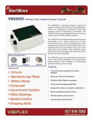
Product Information1.1 IntroductionThe <strong>VS4500</strong> offers the latest <strong>and</strong> most innovative way to incorporate PC clockor GPS synchronized time, voice <strong>and</strong> data throughout your facility, providingyou with the benefits of improved productivity <strong>and</strong> reduced maintenance costs.The <strong>VS4500</strong> wireless controller is a sophisticated time, bell <strong>and</strong> voicemanagement system that can synchronize all facility wireless clocks to oneaccurate atomic time, run a schedule of bells/alerts, initiate live or prerecordedvoice messages <strong>and</strong> send alphanumeric messages to LED displays.Additional features of the <strong>VS4500</strong> include an optional PBX interface <strong>and</strong>optional h<strong>and</strong> held microphone.The <strong>VS4500</strong> uses the PC clock as a time source for wireless analog clocks,wireless digital clocks <strong>and</strong> wireless alphanumeric displays. The <strong>VS4500</strong> can alsobe used to synchronize older wired clocks using a special wireless receiver.Using the connected PC clock or GPS receiver, the <strong>VS4500</strong> updates its internalclock every few minutes <strong>and</strong> sends a wireless data signal every minute toprovide time synchronization information to all system clocks.The <strong>VS4500</strong> is a powerful microprocessor-based desktop paging systemcapable of addressing up to 1000 receivers. It consists of a fully featured encoder with a 2 line by 16-character LCD display<strong>and</strong> a numeric keypad mounted in a wall or desk mountable housing.The <strong>VS4500</strong> is compatible with the <strong>Visiplex</strong> series of digital transmitters ranging from 6 to 300 watts. An internal 6 watttransmitter can be installed at the factory <strong>and</strong> larger transmitters are available as separate items.5
1.2 St<strong>and</strong>ard Features Generate alerts to alphanumeric <strong>and</strong> numeric devices, voice or tone devices, <strong>and</strong> wireless clocks <strong>User</strong> configurable 1000 devices database RS232 serial port for serial communication Built-in high-precision Real-Time clock Capable of synchronizing its internal clock from a PC clock or GPS (requires external GPS receiver) Synchronize both analog <strong>and</strong> digital wireless clocks <strong>User</strong> configurable Master Clock synchronization time External transmitter port Backlit LCD display Numeric keypad Built-in memory backup Desk or wall mountable1.3 Optional Features Telephone line interface (RJ-11) for remote status change of system mode <strong>and</strong> live voice alerts H<strong>and</strong> held microphone for live voice alerts Additional one serial port for extended serial communication Built-in scheduled tone activation for wireless receivers High power external digital transmitters (25 to 300 watt) Automated activation of wireless voice devices from external audio source 900MHz or UHF Wireless receiver for monitoring 900MHz or UHF wireless push buttons <strong>and</strong> transmitters1.4 Package ContentsThe following items are included with the <strong>VS4500</strong>: <strong>VS4500</strong> Wireless Time & Voice Controller Power adaptor <strong>Manual</strong> USB cable (Note: RS232 null-modem communication cable supplied prior to 04/01/2014)1.5 Key NavigationThe following keys also function in system menus as detailed below:# Select / Acknowledge / Enter* Return to previous menu / Escape1 On / Next0 Off / Previous1.6 Display IndicatorsTime source reception status (displayed between the hour <strong>and</strong> minutes segments) <strong>and</strong> daylight saving status (displayed tothe left of the hour segment) indicators are displayed on the main menu:. No connection with time source; No GPS or PC clock data reception detected: GPS or PC clock data reception detected, date <strong>and</strong> time updated* Daylight saving time is active6
1.7 Pre-<strong>Installation</strong> Test for Wireless ClocksIt is recommended to test the <strong>VS4500</strong> <strong>and</strong> the entire system prior to installation in order to verify proper operation <strong>and</strong> getfamiliar with the unit operation.Follow these steps to perform a pre-installation test:1. If your system is equipped with an internal transmitter, connect the BNC antenna cable to the RF-OUT terminal at theback of the <strong>VS4500</strong>.If your system uses an external transmitter, connect the transmitter data cable between the VS101-XX transmitter <strong>and</strong>the DATA I/O port at the back of the <strong>VS4500</strong>. Connect the antenna to the external transmitter’s RF-OUT terminal.2. Connect the provided power supply to the POWER jack at the back of the <strong>VS4500</strong> <strong>and</strong> turn the power switch to ONposition. The main menu should appear with the PAGE TO: displayed on the top line.If you are using an external transmitter, make sure it is powered on.3. Press the B key for the Administration Menu <strong>and</strong> enter the default password (4500). The menu top line should displaySELECT OPTION:4. Press 2 followed by the # key for the internal clock Time Setup. Enter the UTC (Universal Coordinate Time) or GMT(Greenwich Mean Time) time in 24 hours (military) format. The display will change back to Time Setup.5. Press 3 followed by the # key for the internal clock Date Setup. Enter the UTC (Universal Coordinate Time) or GMT(Greenwich Mean Time) date in MMDDYY format. The display will change back to Date Setup.6. Press 6 followed by the # key for the Time Zone Setup menu. Enter the offset in hours of the local time zone from UTC(Universal Coordinate Time) or GMT (Greenwich Mean Time) time. Use 01 to 23 for negative offset (GMT -1 to GMT -23),00 or 24 for GMT time, 25 to 47 for positive offset (GMT+1 to GMT+23).The display will change back to Time Zone Setup.7. Press A followed by the # key for the Wireless Setup menu. Press 3 for the Time Sync Mode menu followed by the #key. Press 1 followed by the # key to enable time synchronization.8. Press the * key to return to the Main Menu.9. Press C to start the transmission of time synchronization every minute (installation mode).Within a few minutes, the <strong>VS4500</strong> will start sending the time information page every minute. Set a clock to receivesignal <strong>and</strong> make sure it receives <strong>and</strong> displays the correct time as displayed on the <strong>VS4500</strong> display.7
2.1 Site Inspection <strong>and</strong> System Location<strong>Installation</strong>Consider the following requirements when planning system installation <strong>and</strong> choosing a location for the <strong>VS4500</strong> <strong>and</strong> othersystem components:1. If the optional GPS receiver is used, it should be installed where it is exposed to the sky, parallel to the horizon <strong>and</strong>unobstructed by trees, power-lines, etc.If the GPS receiver is installed indoors, mount it at the lower edge of a window, away from Low E glass <strong>and</strong> exposed tothe sky.2. Choose a location that is easily accessible in case you need to perform maintenance on the antenna.3. The transmitting antenna should be located as close as possible to the center of the site <strong>and</strong> should not be surroundedby large metal objects that may block the RF signal <strong>and</strong> decrease the coverage range of the system.4. The transmitting antenna may be mounted vertically upward, NEVER horizontally.5. Magnetic Mount antenna (such as VS638) should be attached to a large metal object (like an air duct, metal shelf orcabinet) to provide it with a proper grounding. It may be mounted vertically upward or downward.6. Base Station antenna (such as included with VS654 kit) should be secured to a well-grounded metal structure or to apole on the roof.Locate a path for running the coax cable between the antenna <strong>and</strong> the transmitter such as a riser (if there is no existingpath, create one).Place the external transmitter in a location that is as close as possible to the roof such as in the penthouse. Keep thedistance between the antenna <strong>and</strong> the transmitter as short as possible to minimize RF power loss.2.2 GPS Receiver <strong>Installation</strong> (optional)1. The optional GPS receiver can be mounted indoors or outdoors. Outdoors installation is highly recommended foroptimal reception.2. The GPS receiver should be installed where the distance to the <strong>VS4500</strong> is not more than 100’.3. If the GPS receiver is installed indoor (not recommended), mount it at the lower edge of a window, away from Low Eglass <strong>and</strong> exposed to the sky.4. If the GPS receiver is installed outdoors, mount it in a location protected from direct sun or rain.5. If the GPS receiver is installed outdoors, secure it the structure or to the wall-mounting “L” bracket included with your systemthat allows mounting of the antenna on the side of a building or other structure.6. Connect the GPS receiver to the COM1 serial port <strong>and</strong> set the serial port to the required settings (see page 15 for more details).2.3 Magnetic Mount Antenna (VS638) <strong>Installation</strong>1. Secure the antenna to an adequate grounding surface, HVAC duct or metal “I” beam. The antenna should be mounted verticallyupward or downward, NEVER horizontally.2. Choose a mounting location that will provide an adequate grounding surface <strong>and</strong> free space for RF radiation. If the antenna ismounted too close to metal or closed heavy concrete walls room, a high VSWR may occur which in the long term may causedamage to the transmitter.3. The optional wall-mount “L” bracket allows mounting the magnetic antenna on the side of a building or other structure, providingthe roof’s overhang is not excessive.Note: The antenna should be located as far from the <strong>VS4500</strong> <strong>and</strong> transmitter as the coax cable allows.2.4 Base Station Outdoor Antenna Kit (VS654) <strong>Installation</strong>1. To achieve maximum performance for your outdoor antenna choose a location that is unobstructed by trees, branches, powerlines,etc. Never mount the antenna where there is a signal-reflecting surface such as metal, power lines, mirrored glass, etc.2. Choose a location that is easily accessible in case you need to perform maintenance on the antenna.8
3. For optimal performance, make sure the antenna is installed at an elevation that will provide sufficient clearance to allow yourantenna to radiate without interference.4. It is recommended to mount the antenna where the path of the antenna cable is straight <strong>and</strong> as close as possible to the systemtransmitter. Do not coil up 100 feet of coaxial cable when only 20 feet of cable is required. Use a RG-8U coax cable that isspecified as Low Loss to minimize power loss.5. The antenna may be mounted vertically upward, NEVER horizontally.6. Install the grounding kit provided with the VS654 antenna kit.Note: The antenna should be located as far from the <strong>VS4500</strong> <strong>and</strong> transmitter as the coax cable allows.2.5 <strong>VS4500</strong> Encoder <strong>and</strong> External Transmitter <strong>Installation</strong>The <strong>VS4500</strong> system encoder can be installed on a wall or shelf. Install a UPS power backup to protect the system from poweroutages <strong>and</strong> surges. If you are using an external transmitter, place it next to the <strong>VS4500</strong> <strong>and</strong> use the data cable provided toconnect <strong>VS4500</strong> <strong>and</strong> the external transmitter.Once the transmitter <strong>and</strong> antenna are placed properly, connect them to the <strong>VS4500</strong> <strong>and</strong> the transmitter as follows:1. If an external transmitter is used, connect the antenna to the RF-OUT terminal at the back of the external transmitter. Connectthe transmitter data cable between the VS101-XX transmitter <strong>and</strong> the DATA I/O port at the back of the <strong>VS4500</strong>.Otherwise, connect the antenna to the RF-OUT terminal at the back of the <strong>VS4500</strong>.2. If the optional GPS receiver is used, the internal clock of the <strong>VS4500</strong> will be set to the UTC time <strong>and</strong> the <strong>VS4500</strong> willstart transmitting the local time every minute.3. If the PC time is used, connect the PC serial port to the COM1 terminal <strong>and</strong> run the TimeSync or VPS software. SeeSetting Date <strong>and</strong> Time from PC section on page 24 or TimeSync section on page 33 for more detailed information.4. No additional programming is needed for the system to be fully operational. See Advanced System Informationsection on page 10 for more detailed information about the <strong>VS4500</strong>.Note: Do not place the <strong>VS4500</strong> on top of the external transmitter as RF feedback may cause system malfunction.9
Advanced System InformationThe main menu shown below appears after the <strong>VS4500</strong> is turned on <strong>and</strong> is used for accessing the Programming <strong>and</strong>Administration menus. This menu is also used for sending a page to a receiver.PAGE TO: 11:553.1 Administration MenuFrom the Main Menu press the B key. Enter 4500 as password. The prompt Select Option will appear on the top line.The Administration Menu provides access to the following available sub-menus:1. Device Database2. Time Setup3. Date Setup4. View Messages5. Coverage Test6. Time Zone Setup7. Last Message8. Reset Database9. Sunset/SunriseA. Wireless SetupB. Operations ModesC. System SetupD. TX Test ToneTo access a specific sub-menu, press the digit key representing it.3.1.1 Device Database MenuFrom the Administration Menu, select 1 followed by the # key. Following are the fields description:Device to EditDevice CapcodeDevice TypePaging ModeGroupEnter 3 digit ID of the programmed device (001-899).If the device already exists, its details will be displayed for editing or deleting.Group devices (01-99) are represented <strong>and</strong> accessed by paging to devices 901-999.Enter the capcode of the programmed device. For Voice pagers, enter “0” followed by Tone A<strong>and</strong> Tone B (for example, “0110111”).Select the type of the programmed device.0 - Alphanumeric Pager1 - Numeric Pager2 - Tone Only Pager3 - Voice Pager4 - Wireless Speaker5 - Widearea Pager (Note: Optional modem is required)6 - Portable Radio7 - Phone8 - LED Display9 - Intercom StationSelect Mode <strong>and</strong> Baud Rate <strong>and</strong> press the # key:1 – 512 bps, Mode 02 – 512 bps, Mode 13 - 512 bps, Mode 24 – 512 bps, Mode 35 – 1200 bps, Mode 06 – 1200 bps, Mode 17 - 1200 bps, Mode 28 – 1200 bps, Mode 39 – 2400 bps, Mode 10 – 2400 bps, Mode 2If the device is a member in a group, enter the group number (0-99) <strong>and</strong> press the # key.Group devices are represented <strong>and</strong> accessed by paging to devices 901-999.10
Press the * key to return to the Administration Menu.3.1.5 Coverage Test MenuFrom the Administration Menu, select 5 followed by the # key. Enter a value between 1 <strong>and</strong> 8 to determine the coverpage interval:1 – Every 5 seconds2– Every 10 seconds3 – Every 15 seconds4 – Every 20 seconds5 – Every 30 seconds6 – Every 1 minute7 – Every 2 minutes8 – Every 4 minutesUse this option to send cover page to device 100. This feature is useful when testing the transmitter coverage area.Press * to cancel <strong>and</strong> return to the Administration Menu.3.1.6 Time Zone Setup MenuFrom the Administration Menu, select 6 followed by the # key. The following screen will be displayed:TIME ZONE SETUP:06Enter the offset in hours of the local time zone from UTC (Universal Coordinate Time) or GMT (Greenwich Mean Time) time.Use 01 to 23 for negative offset (GMT -1 to GMT -23), 00 or 24 for GMT time, 25 to 47 for positive offset (GMT+1 toGMT+23).For examples, for the following time zones, enter the following values:Eastern Time: 05Central Time: 06Mountain Time: 07Pacific Time: 08Alaska Time: 09Hawaii Time: 10After the last step is completed, the display will return to the Administration Menu.3.1.7 Last Message MenuFrom the Administration Menu, select 7 followed by the # key.Use this option to display the last message sent to a device.Press * to cancel <strong>and</strong> return to the Administration Menu.3.1.8 Reset Database MenuNOTE: This is an IRREVERSIBLE comm<strong>and</strong> - DO NOT select this option unless you are absolutely sure you want to clearall devices <strong>and</strong> pre-programmed messages data.You may want to transcribe this information to paper first or use the optional PC software to backup the data to a computer.From the Administration Menu, select 8 followed by the # key.CLEAR ALL DATA..ARE YOU SURE???Press # to confirm the Database Reset. Press * or any other key to cancel <strong>and</strong> return to the Administration Menu.3.1.9 Sunset / Sunrise MenuUse this option to display the current settings for sunset <strong>and</strong> sunrise.From the Administration Menu, select 9 followed by the # key. The following screen will be displayed:12
SUNSET/SUNRISE:R06:22 S17:43Following is the description of the displayed information:R: Sunrise time as indicated by the following 5 charactersS: Sunset time as indicated by the following 5 charactersPress the * key to return to the Administration Menu.3.1.10 Wireless Setup MenuFrom the Administration Menu, select A followed by the # key. The following screen will be displayed:WIRELESS SETUP:PA VOLUMEThis screen allows the administrator to configure different wireless settings of the <strong>VS4500</strong>.Press the key representing the field followed by # key to edit the settings. Following are the fields description:1 - PA Volume2 - PA Timeout3 - Time Sync Mode4 – DL Saving Mode5 – Time Sync Slot6 – Daytime Sync7 – MC Sync TimeDetermines the default volume used in voice messaging. Enter a value of 1 (lowest), 2, 3 or 4(highest) followed by # key to save the settings.Determines the time period after which the transmission of voice message will be terminated.Enter a value between 1 <strong>and</strong> 8 followed by # key to save the settings:1 – 30 seconds2 – 60 seconds3 – 1.5 minutes4 – 2 minutes5 – 2.5 minutes6 – 3 minutes7 – 3.5 minutes8 – 4 minutesDetermines if time synchronization signal should be sent to wireless clocks. Enter a valuebetween 0 <strong>and</strong> 2 followed by # key to save the settings:0 – Disabled1 – Enabled2 – Controlled by a PC softwareDetermines if time synchronization Daylight Saving time is on or off. Enter a value between 0<strong>and</strong> 1 followed by # key to save the settings:0 – Disabled1 – EnabledDetermines when the time synchronization signal should be sent. Enter a value between 0 <strong>and</strong>6 followed by # key to save the settings:0 – 15 seconds after top of the minute for TS4xxx <strong>and</strong> TS5xxx clocks.1 – 30 seconds after top of the minute for TS4xxx <strong>and</strong> TS5xxx clocks.2 – 45 seconds after top of the minute for TS4xxx <strong>and</strong> TS5xxx clocks.3 – Top of the minute for TS4xxx <strong>and</strong> TS5xxx clocks.4 – Top of the minute for TS-CLK-xxxx clocks, 15 seconds after top of the minute for TS4xxx<strong>and</strong> TS5xxx clocks.5 – Top of the minute for TS-CLK-xxxx clocks, 30 seconds after top of the minute for TS4xxx<strong>and</strong> TS5xxx clocks.6 – Top of the minute for TS-CLK-xxxx clocks, 45 seconds after top of the minute for TS4xxx<strong>and</strong> TS5xxx clocks.Determines if time synchronization signal should be sent during daytime or only duringnighttime. Enter a value between 0 <strong>and</strong> 1 followed by # key to save the settings:0 – Activate time synchronization signal during nighttime only (1:50AM to 2:10AM, 12AM to3:30 AM on Day Light Saving change date).1 – Activate time synchronization every minute during daytime.Determines the time when a wireless signal should be sent to a Master Clock Synchronizer toclose contact.Enter a valid time in 24 hours format (for example, for 6PM,enter 1800).13
Determines the Master Clock Synchronizer contact closure time interval (seconds). Enter avalue between 0 <strong>and</strong> 9 followed by # key to save the settings:0 – Disabled1 – 1 seconds2 – 2 seconds3 – 3 seconds8 – MC Sync Duration4 – 4 seconds5 – 5 seconds6 – 6 seconds7 – 7 seconds8 – 8 seconds9 – 9 secondsDetermines if secure data mode should be used. This provides data encryption to secure thetransmission to the wireless receivers using the security key. Enter a value between 0 <strong>and</strong> 9followed by # key to save the settings:0 – Disabled1 – Mode 12 – Mode 29 – Security Mode 3 – Mode 34 – Mode 45 – Mode 56 – Mode 67 – Mode 78 – Mode 89 – Mode 9Determines the security key for secure data mode.0 – Security CodeEnter a value between 0 <strong>and</strong> 299.Indicates if the type <strong>and</strong> status of the event schedule. Enter a value between 1 <strong>and</strong> 3 followedby # key to save the settings:1 – WeeklyA – Schedule Paging 2 – Calendar3 – Idle (st<strong>and</strong>by mode)Note: This setting is applicable only when the schedules events option was ordered <strong>and</strong>installed on the <strong>VS4500</strong>.Determines the active weekly Event Schedule.Enter a value between 1 <strong>and</strong> 4 followed by # key to save the settings.B – Schedule SlotNote: This setting is applicable only when the schedules events option was ordered <strong>and</strong>installed on the <strong>VS4500</strong>. The setting applies to weekly schedule only.Determines the TX deviation. Enter a value between 1 <strong>and</strong> 9 followed by # key to save thesettings:1 – ±0.5kHz2 – ±1.0kHz3 – ±1.5kHzC – TX Deviation 4 – ±2.0kHz5 – ±2.5kHz6 – ±3.0kHz7 – ±3.5kHz8 – ±4.0kHz9 – ±4.5kHzDisplays the call sign assigned to you by the FCC (if any). Contact <strong>Visiplex</strong> tech support forD – Call Signmore details.Note: Underlined values indicate default values.Press the * key to return to the Administration Menu.3.1.11 Operation Modes MenuFrom the Administration Menu, select B followed by the # key. The following screen will be displayed:OPERATIOS MODES:PRE-PAGE DELAYThis screen allows the administrator to configure global settings of the <strong>VS4500</strong>.Press the key representing the field followed by # key to edit the settings. Following are the fields description:1 - Pre-Page DelayDetermines if a delay will be applied before the transmission of data for digital paging. Enter avalue between 0 <strong>and</strong> 1 followed by # key to save the settings:0 – Disabled1 – Enabled14
2 - Intercom3 - LBT Mode4 - Two-Channel Mode5 - Auto Speaker6 - Auto Phone Page7 - Speaker Level8 – TX ALC9 – LED Display Mode0 – MIC PTT ModeA – LED ColorB – LED Text ModeC – Led Font StyleD – LED Timeout ModeDetermines the mode of the 2-way intercom feature. Enter a value between 0 <strong>and</strong> 2 followedby # key to save the settings:0 – Disabled1 – Enabled2 – full-duplex modeDetermines if the Listen before Transmit is activated. Enter a value between 0 <strong>and</strong> 1 followedby # key to save the settings:0 – Disabled1 – EnabledDetermines if different frequencies should be used for different type of transmissions. The 1stchannel will be used for st<strong>and</strong>ard paging <strong>and</strong> PA while the 2nd channel will be used for wirelessclocks. Enter a value between 0 <strong>and</strong> 1 followed by # key to save the settings:0 – Disabled1 – EnabledNote: This feature requires supporting transmitter with two channels set to differentfrequencies.Determines if the system will automatically transmit messages to the pre-assigned device(usually 898) when the microphone's PTT is activated. Enter a value between 0 <strong>and</strong> 1 followedby # key to save the settings:0 – Disabled1 – EnabledDetermines if the system will automatically transmit messages to the pre-assigned device(usually 899) when a call is received on the telephone interface is activated. Enter a valuebetween 0 <strong>and</strong> 1 followed by # key to save the settings:0 – Disabled1 – EnabledDetermines the default volume level of the <strong>VS4500</strong> internal speaker used for 2-waycommunication with intercom stations. Enter a value between 0 <strong>and</strong> 9 followed by # key tosave the settings.Determines if the Automatic Level Control is activated for voice transmissions. Enter a valuebetween 0 <strong>and</strong> 1 followed by # key to save the settings:0 – Disabled1 – EnabledDetermines if the messages sent to alphanumeric display should overwrite the displayedmessage or added to the current queue of messages displayed by the alphanumeric display.Enter a value between 1 <strong>and</strong> 2 followed by # key to save the settings:1 – New messages overwrite the currently displayed message.2 – New messages are added to the list of messages (messages will be displayed one after theother according to the messages parameters).Determines if the wireless speaker controllers (such as VNS2200) should be muted when themicrophone PTT is off to reduce background audio. Enter a value between 0 <strong>and</strong> 1 followed by# key to save the settings:0 – Wireless speaker controllers are not muted when the microphone PTT is off.1 – Wireless speaker controllers are muted when the microphone PTT is off.Note: This feature requires compatible wireless speaker controller.Determines the default color that should be used to display messages sent to alphanumericdisplays. Enter a value according to the settings supported by the alphanumeric display.Note: Please refer to the alphanumeric display instructions sheet for more information.Determines the default effect that should be used to display messages sent to alphanumericdisplays. Enter a value according to the settings supported by the alphanumeric display.Note: Please refer to the alphanumeric display instructions sheet for more information.Determines the default font that should be used to display messages sent to alphanumericdisplays. Enter a value according to the settings supported by the alphanumeric display.Note: Please refer to the alphanumeric display instructions sheet for more information.Determines the default time slice that should be used to display messages sent toalphanumeric displays. Enter a value according to the settings supported by the alphanumericdisplay.Note: Please refer to the alphanumeric display instructions sheet for more information.Press the * key to return to the Administration Menu.3.1.12 System Setup MenuFrom the Administration Menu, select C followed by the # key. The following screen will be displayed:SYSTEM SETUP:COM1 PROTOCOLThis screen allows the administrator to configure the <strong>VS4500</strong> as required for the application.15
Press the key representing the field followed by # key to edit the settings. Following are the fields description:1 – COM1 Protocol2 – COM1 Baud Rate3 – COM2 Protocol4 – COM2 Baud Rate5 – USB Mode6 – System PasswordEnter the serial communication protocol that should be used on COM1. Enter a value between1 <strong>and</strong> 9 or A followed by # key to save the settings:1 – TAP2 – COMP13 – COMP24 – VISIPLEX5 – GPS SYNC6 – FREETEXT7 – 900MHz Receiver8 – VPR Receiver9 – PC-ADMINA – WIDEAREAEnter the serial communication settings (baud rate, parity, data bits, stop bits) that should beused on COM1. Enter a value between 0 <strong>and</strong> 9, A or B followed by # key to save the settings:0 – 300 bps, 7,E,11 – 300 bps, 8,N,12 – 1200 bps, 7,E,13 – 1200 bps, 8,N,14 – 2400 bps, 7,E,15 – 2400 bps, 8,N,16 – 9600 bps, 7,E,17 – 9600 bps, 8,N,18 – 19200 bps, 7,E,19 – 19200 bps, 8,N,1A – 38400 bps, 7,E,1B – 38400 bps, 8,N,1Enter the serial communication protocol that should be used on COM2. Enter a value between1 <strong>and</strong> 9 or A followed by # key to save the settings:1 – TAP2 – COMP13 – COMP24 – VISIPLEX5 – GPS SYNC6 – FREETEXT7 – 900MHz Receiver8 – VPR-01 Receiver9 – PC-ADMINA – WIDEAREAEnter the serial communication settings (baud rate, parity, data bits, stop bits) that should beused on COM2. Enter a value between 0 <strong>and</strong> 9, A or B followed by # key to save the settings:0 – 300 bps, 7,E,11 – 300 bps, 8,N,12 – 1200 bps, 7,E,13 – 1200 bps, 8,N,14 – 2400 bps, 7,E,15 – 2400 bps, 8,N,16 – 9600 bps, 7,E,17 – 9600 bps, 8,N,18 – 19200 bps, 7,E,19 – 19200 bps, 8,N,1A – 38400 bps, 7,E,1B – 38400 bps, 8,N,1Determines if the serial protocol used by the USB port. Enter a value between 1 <strong>and</strong> 2 followedby # key to save the settings:1 – VISIPLEX protocol2 – PC-ADMIN protocolEnter the new administrator password that will be required to access the Administration Menu.The default password is 4500.16
7 – VOX Mode8 – PABX Voice9 – Time StampA – RX Data PolarityB – TX Data PolarityDetermines the sensitivity level <strong>and</strong> timeout interval for automated paging to the Auto SpeakerPaging device (usually 898). The Auto Speaker device will be activated when audio is detectedon the VOX port <strong>and</strong> transmission will be terminated when no audio is detected after thetimeout interval elapsed.Low Sensitivity requires high audio input <strong>and</strong> High Sensitivity requires lower audio input.Enter a value between 0 <strong>and</strong> 9 followed by # key to save the settings:0 – Disabled1 – VOX Mode 1 (High sensitivity, 4 seconds timeout)2 – VOX Mode 2 (Medium sensitivity, 4 seconds timeout)3 – VOX Mode 3 (Low sensitivity, 4 seconds timeout)4 – VOX Mode 4 (High sensitivity, 8 seconds timeout)5 – VOX Mode 5 (Medium sensitivity, 8 seconds timeout)6 – VOX Mode 6 (Low sensitivity, 8 seconds timeout)7 – VOX Mode 7 (High sensitivity, 16 seconds timeout)8 – VOX Mode 8 (Medium sensitivity, 16 seconds timeout)9 – VOX Mode 9 (Low sensitivity, 16 seconds timeout)Determines if a voice prompt should be played when a user dials in to the system in order tosend a message using a phone keypad. Enter a value between 0 <strong>and</strong> 1 followed by # key tosave the settings:0 – Disabled1 – EnabledDetermines if a time stamp should be added to outgoing message. Enter a value between 0<strong>and</strong> 1 followed by # key to save the settings:0 – Disabled1 – EnabledDetermines if the receive data is inverted. Enter a value between 0 <strong>and</strong> 1 followed by # key tosave the settings:0 – Normal1 – InvertedDetermines if the transmitter data should be inverted. Enter a value between 0 <strong>and</strong> 1 followedby # key to save the settings:0 – Normal1 – InvertedC – Pre-Sunset Time Determines the time offset in minutes from the sunset time. Enter a value from 0 to 99.D – Past Sunrise TimeDetermines the time offset in minutes from the sunrise time. Enter a value from 0 to 99.Note: Sunset/Sunrise light control provides support for automated messaging to devicesbased on the sunset <strong>and</strong>/or sunrise time of each day. The activation <strong>and</strong> deactivation time canbe set to an offset of 0 to 99 minutes before sunset <strong>and</strong>/or after sunrise time. The activateddevices will receive a comm<strong>and</strong> from the <strong>VS4500</strong> at these times <strong>and</strong> perform a task such asclosing or opening dry-contacts.Notes: 1. Underlined values indicate default values.2. St<strong>and</strong>ard paging protocols supported are <strong>Visiplex</strong>, TAP, COMP1 <strong>and</strong> COMP2.3.2 <strong>Installation</strong> Mode Menu<strong>Installation</strong> Mode forces the system to transmit the time information every minute. This mode is helpful when the system isbeing installed or when conducting a site coverage test.NOTE: This feature is available only if Time Sync Mode was enabled. <strong>Installation</strong> Mode should be disabled after thecoverage test is completed to allow proper system operation.From the Main Menu press the C key to enable <strong>and</strong> disable the <strong>Installation</strong> Mode. The following screen will be displayed:SYNC IS ONThe display will return to the Main Menu. Press the C key again to disable the <strong>Installation</strong> Mode.3.3 Page To MenuThe main menu shown below appears after the <strong>VS4500</strong> is turned on <strong>and</strong> is also used for sending a page to a device.PAGE TO: 11:5517
The <strong>VS4500</strong> supports 999 devices that are accessible by entering the device number on the above menu. The devicenumber is a 3 digits number between 001 <strong>and</strong> 999 that uniquely represents each device.Devices 001 to 900 are devices that allow access to individual devices while devices 901 to 999 are pre-programmed asgroup devices. Group devices allow easy access to multiple devices that are members of the group.Follow these steps to send a page using the keypad:1. Program a device in to the <strong>VS4500</strong> as described in the Device Database Menu section (page 10).2. Enter the device number as a 3 digit number.3. If the selected device is a Tone / Vibrate device, the page will be sent immediately after entering the device number.If the device selected is an Alphanumeric or a Numeric device, the following screen will be displayed:ENTER MESSAGE:_4. Enter a numeric message that will not exceed 16 characters. To send one of the preprogrammed alphanumericmessages, enter * followed by the message number (see PABX Messages on page 21).The page will be sent immediately after entering the 16 th character or after the # is pressed.3.4 Accessing Wireless Devices via TelephoneNote: Sending alerts using a telephone requires the optional Telephone Line Interface <strong>and</strong> Alpha by Phone features<strong>and</strong> may not be available on your <strong>VS4500</strong>.3.4.1 Accessing St<strong>and</strong>ard Devices1. Program a device in to the <strong>VS4500</strong> as described on Device Database Menu section on page 10.2. Connect the RJ-11 PHONE jack located at the back of the <strong>VS4500</strong> to an analog telephone line or extension.3. Using another phone, dial the number of the telephone line or extension connected to the <strong>VS4500</strong>.4. The <strong>VS4500</strong> will answer the call with the “Please Enter Pager” prompt.5. Enter the device number as a 3 digit number. The device number can be also entered without leading zeros but it willhave to be followed by the # key. If the device number entered is not valid, the <strong>VS4500</strong> will respond with “InvalidPager” prompt.6. If the selected device is Tone / Vibrate device, the page will be sent immediately after entering the device number <strong>and</strong>the <strong>VS4500</strong> will respond with “Page Sent” prompt.7. If the selected device is an Alphanumeric or a Numeric device, the <strong>VS4500</strong> will respond with “Please Enter Message”prompt.For Numeric or Alphanumeric devices, enter a numeric message using the telephone keypad (to send alphanumericmessages, see PABX Messages on page 21).8. If the selected device is a Voice pager or Wireless Speaker device, the <strong>VS4500</strong> will respond with “Please Wait” prompt<strong>and</strong> shortly after that with the “Please Speak Message” prompt.To send a live voice message, speak your message.9. To send the message, press #. The <strong>VS4500</strong> will respond “Page Sent” prompt (for devices that are not live voicedevices).3.4.2 Accessing Wireless Voice or Tone ReceiversFollow these steps to send a voice message or a tone to a speaker by dialing in from a telephone:1. For live voice messaging, program a Wireless Speaker device in to the <strong>VS4500</strong>. For tone only or pre-programmed voicemessaging, program an alphanumeric device in to the <strong>VS4500</strong>. Verify that the speaker capcode was programmedproperly (Device Type should be set to Alphanumeric Pager).2. Using another phone, dial the number of the telephone line or extension connected to the <strong>VS4500</strong>.3. The <strong>VS4500</strong> will answer the call with “Please Enter Pager” prompt.4. To send a voice message, enter a Wireless Speaker device number as a 3 digit number (for example, “105”). If required,to send a voice message in a specific volume level, enter *vppp where:v is the Volume (digit between 1 <strong>and</strong> 4)ppp is the Wireless Speaker device number18
5. To send a tone, enter an alphanumeric device number as a 3 digit number (for example, “105”). If the device numberentered is not valid, the <strong>VS4500</strong> will respond with “Invalid Pager” prompt (for phone access only).Note: The device number can be also entered without leading zeros but it will have to be followed by the # key.6. The <strong>VS4500</strong> will respond with “Please Wait” prompt <strong>and</strong> shortly after that with the “Please Speak Now” prompt.7. To send a live voice message, speak your message.8. To send a tone or pre-programmed voice, enter a message using the formats below:For encoders supporting up to 8 tones:t is the Alert Type (digit between 1 <strong>and</strong> 8)l is the Length (digit between 0 <strong>and</strong> 9. Note: Length value is applicable to pre-programmed tones only. Use any valuefor all other voice or tone messages)v is the Volume (digit between 1 <strong>and</strong> 4)d is the Delay (optional, digit between 0 <strong>and</strong> 9)r is the Repeat (optional, digit between 0 <strong>and</strong> 9)For example, to send tone 4 with length 5, volume 2, 6 repeats <strong>and</strong> a delay of 4 seconds between each repeat, enter**945246.For encoders supporting more than 8 tones:t is the Alert Type (two digits number from 01 to the number of alerts supported by the receiver)l is the Length (digit between 0 <strong>and</strong> 9. Note: Length value is applicable to pre-programmed tones only. Use any valuefor all other voice or tone messages)v is the Volume (digit between 1 <strong>and</strong> 4)d is the Delay (optional, digit between 0 <strong>and</strong> 9)r is the Repeat (optional, digit between 0 <strong>and</strong> 9)For example, to send tone 14 with length 5, volume 2, 6 repeats <strong>and</strong> a delay of 4 seconds between each repeat, enter**8145246.9. To send the message, press #.The <strong>VS4500</strong> will respond with “Page Sent” prompt (for phone access only).3.5 Accessing Wireless Voice Receivers via MicrophoneFollow these steps to send a live voice message to a speaker using a microphone:1. For live voice messaging, program a Wireless Speaker device in to the <strong>VS4500</strong>. Verify that the speaker capcode wasprogrammed properly (Device Type should be set to Wireless Speaker).2. From the <strong>VS4500</strong> Main Menu, Enter a Wireless Speaker device number as a 3 digit number (for example, “105”).3. Wait for the “Speak Now” prompt at the bottom of the screen.4. Press the PTT button on the microphone <strong>and</strong> speak your message.5. Press the * key to end the transmission.3.6 Initiating <strong>and</strong> Answering Intercom CallsNote: Intercom communication allows one way communication at any given time. You must allow the other party to finishtalking before you can talk back.Some system may have been set to Full Duplex or H<strong>and</strong>s-Free operation modes (not supported by all versions, requiressupporting base station <strong>and</strong> intercom station). In Full Duplex mode, the party on the intercom station is only required toaccept the call <strong>and</strong> after that can communicate without pressing <strong>and</strong> holding the intercom station button.In H<strong>and</strong>s-Free mode, the party on the intercom station is NOT required to accept the call. The communication isestablished automatically as soon as the call is received from the base station. As a result, when this mode is activated, thebase station can listen to the intercom station area without any notification or indication to the party on the intercomstation.For additional settings, see DSC field on page 10.Base Station OperationFollow these steps to initiate a call from the base station to an intercom station:1. From the <strong>VS4500</strong> Page To menu, enter an Intercom device number as a 3 digit number (for example, “501”).2. Wait for the call to be accepted by the party on the intercom station (the intercom station will sound beeping tones toalert of the incoming call).19
Note: Systems set to h<strong>and</strong>s-free operation do not require the intercom station to accept the call.3. Once the call request was accepted, the STATION IS ON message will be displayed on the <strong>VS4500</strong>. Press <strong>and</strong> hold thePTT button on the microphone while speaking.4. Press the * key to end the conversation.Follow these steps to answer a call from an intercom station:1. When an intercom station is initiating a call to the base station, the base station will sound beeping tones to alert of theincoming call. Press the # key to accept the call.2. Press <strong>and</strong> hold the PTT button on the microphone while speaking.3. Press the * key to end the conversation.Intercom Station OperationFollow these steps to initiate a call from an intercom station to the base station:1. Push the button on the intercom station.2. Wait for the call to be accepted by the party on the base station (the base station will sound beeping tones to alert of theincoming call).3. Once the call request was accepted, press <strong>and</strong> hold the button on the intercom station while speaking.Note: Systems set to Full-Duplex or H<strong>and</strong>s-Free operation do not require the user to press <strong>and</strong> hold the button whilespeaking.Follow these steps to answer a call from the base station:1. When a base station is initiating a call to the intercom station, the intercom station will sound beeping tones to alert ofthe incoming call. Press the button on the intercom station to accept the call.Note: Systems set to H<strong>and</strong>s-Free operation do not require the user to press the button to accept the call. The call isaccepted automatically as soon as the request is received from the base station.2. Press <strong>and</strong> hold the button on the intercom station while speaking.Note: Systems set to Full-Duplex or H<strong>and</strong>s-Free operation do not require the user to press <strong>and</strong> hold the button whilespeaking.3. For systems set to H<strong>and</strong>s-Free operation: Press the intercom button to end the conversation.3.7 Background Music (FM Radio) Setup on Wireless AmplifiersNote: Background FM radio music feature is supported by wireless amplifiers (such as VNS2200) equipped with theVNS2265 option). A Local dedicated FM radio transmitter is required <strong>and</strong> it has to transmit on the frequency supported bythe wireless amplifier.Since the <strong>VS4500</strong> does not utilize a full keyboard, use the VPS software to send the alphanumeric comm<strong>and</strong>s (see ).Follow these steps to activate or deactivate the FM radio background music on wireless amplifiers:1. Program an alphanumeric device in to the <strong>VS4500</strong>. Verify that the wireless amplifier / speaker capcode was programmedproperly (Device Type should be set to Alphanumeric Pager).2. Connect to the <strong>VS4500</strong> using the VPS software <strong>and</strong> click on System Devices & Messaging.3. On the VPS software device list, click on the alphanumeric device programmed on step 1.4. To activate the FM radio background music for a specific time interval, enter a message using the GMthvds format inthe VPS software message field:t is always 95h is hundredth digit of the time interval (digit between 0 <strong>and</strong> 9)v is the Volume (digit between 1 <strong>and</strong> 4)d is tenth digit of the time interval (digit between 0 <strong>and</strong> 9)s is single digit of the time interval (digit between 0 <strong>and</strong> 9)For example, to activate the FM background music for 125 minutes with volume 2, enter GM951225.5. To deactivate the FM radio background music, enter GM960100 in the VPS software message field.6. On the VPS software click on Send Page to send the comm<strong>and</strong>.20
Follow these steps to change the FM radio background music frequency stored on the wireless amplifiers:1. Program an alphanumeric device in to the <strong>VS4500</strong>. Verify that the wireless amplifier / speaker capcode was programmedproperly (Device Type should be set to Alphanumeric Pager).2. Connect to the <strong>VS4500</strong> using the VPS software <strong>and</strong> click on System Devices & Messaging.3. On the VPS software device list, click on the alphanumeric device programmed on step 1.4. Enter a message using the FMsvbf* format in the VPS software message field:s is the squelch or signal threshold level (digit between 0 <strong>and</strong> 9, 0 is Lowest, 9 is Highest)v is the Preamplifier Volume (digit between 1 <strong>and</strong> 9, 1 is Lowest, 9 is Highest)b is the B<strong>and</strong>width (always 5)f is the FM radio frequency in MHz (7 digits, no decimal points)For example, to set the FM receive frequency to 95.7 MHz with squelch level of 3, enter FM3150957000 followed by *.5. On the VPS software click on Send Page to send the comm<strong>and</strong>.3.8 Pre-Programmed MessagesThe <strong>VS4500</strong> support the following optional pre-programmed messages:1 - PABX Messages2 - FreeText Messages3 - Wireless DevicesThese messages can only be programmed using a PC software such as the VPS (see page 23 for more details).3.8.1 PABX MessagesPABX (Alpha by Phone) messages provide support for user initiated alphanumeric messaging by dialing in to the <strong>VS4500</strong><strong>and</strong> entering the device number <strong>and</strong> message using a telephone keypad.Typically, when users dial in to the <strong>VS4500</strong>, they will be able to send numeric messages only using the telephone keypad.The PABX messages allow the users to enter a message code, which represents an alphanumeric message. In this case, thealphanumeric message will be sent instead of the message code.Following are the fields description:MessageDetermines the message that should be sent for the selected PABX message code. Forexample, if the user enters “*05”, the actual message will be the alphanumeric messageprogrammed as PABX message 5.Note: The <strong>VS4500</strong> supports 99 PABX messages.3.8.2 FreeText Messages MenuFreeText messages provide support for detecting keywords in data received by the serial port. If the keyword is found, the<strong>VS4500</strong> can send a message to the assigned device.Following are the fields description:Send to DeviceReplace TextKeytextNewtextEnter the number of the device that should receive the message when the selected keyword isdetected.Determines if the received text should be replaced with the text in the Newtext field if thekeyword is found in the received serial data.Determines the keyword that should be sought for in the received serial data. If the keyword isfound, the whole serial data string or the text in the Newtext field will be sent to the assigneddevice (depending on the setting in the Replace Text field).Determines the text that should be sent to the assigned device if the keyword is found in thereceived serial data.Note: The <strong>VS4500</strong> supports 99 FreeText messages.3.7.3 Wireless Devices MenuWireless devices messages provide support for automated messaging activated by 900MHz or UHF wireless pendants orpush button transmitters.Each pendant sends a wireless signal containing its ID (usually a 3 or 7 digit number). When a signal is received by theoptional wireless receiver, it is compared to the list of ID stored in the <strong>VS4500</strong>. If a match is found, the <strong>VS4500</strong> will send amessage to the assigned device with the assigned message.21
Notes: Wireless 900MHz or UHF serial receiver is required to activate these messages.If multiple matches are found, the <strong>VS4500</strong> will send a message corresponding to each match to respective assigned devicewith the respective assigned message.Following are the fields description:Wireless CodeEnter the ID of the wireless device that should trigger a message.Determines if the device is supervised. If a signal is not received from a supervised device, theSupervised<strong>VS4500</strong> will send an alert.Enter the number of the device that should receive the message when the selected wirelessSend to Devicecode is detected.Determines when the device monitoring is active. The system will send a message to thedesignated device only if the wireless pendant device is triggered during the monitored time.Enter a number from 0 to 9.0 - Always Active1 - Daily, 6PM-8AM2 - Weekdays Only, 6PM-8AM3 - Daily, 8PM-6AM4 - Daily, 10PM-6AMActivity Plan5 - Daily, 10PM-5AM6 - Daily, 6AM-10PM7 - Weekdays Only, 6AM-10PM8 - Daily, 8AM-6PM9 - Weekdays Only, 8AM-6PMNote: The execution of the activity plan is dependent on the time stored the <strong>VS4500</strong> internalclock. This clock should be kept accurate by receiving time updates from a GPS receiver orfrom a PC connected to the <strong>VS4500</strong> via a serial port.Determines if the message should be repeated as long as no cancel transmission is receivedfrom pendant, <strong>and</strong> the maximum number of repeat messages. The message will be repeatedRepeat Pageevery minute.Enter a number from 00 to 99.Enter the ID of the wireless pendant device that should trigger a cancel message.Cancel CodeCancellation message will be sent when this ID is received <strong>and</strong> will add the word “Cancel” tothe message.Determines if the message will be sent when a Normal call (Buttons 1-4), Cancel call orTamper call is received from the pendant device.Call TypeNote: This field is supported by <strong>VS4500</strong> version 1.05 <strong>and</strong> higher.Differentiation between buttons 1-4 on multiple button pendants is supported by pendantsfrom the EN series only <strong>and</strong> <strong>VS4500</strong> version 3.20 <strong>and</strong> higher.Determines the message that should be sent to the assigned device when the selectedMessagependant button is pressed or released.Note: Underlined values indicate default values.Note: The <strong>VS4500</strong> supports 500 Wireless Devices messages.22
Software4.1 VPSThe optional VPS software allows you to program <strong>and</strong> backup the <strong>VS4500</strong> databases, create scheduled events (tones, bells<strong>and</strong> device activation) <strong>and</strong> synchronize the <strong>VS4500</strong> date <strong>and</strong> time to the PC clock.Note: The VPS software supports <strong>VS4500</strong> version 1.05 <strong>and</strong> up. If you are using a <strong>VS4500</strong> with earlier version, refer to theVisiDB software <strong>and</strong> a previous version of the <strong>VS4500</strong> manual for details.4.1.1 ConnectionsFollow these steps to connect the <strong>VS4500</strong>:1. Connect the provided null modem cable to the COM1 port <strong>and</strong> the other end to one of the serial port on the PC. Make anote of the PC serial port used (COM1, COM2, etc.).For computers without serial ports, connect a USB cable (not provided) between the USB port <strong>and</strong> the PC. Install theUSB drivers provided with the VPS software according to Windows operating system used (32 or 64 bit).Note: The USB drivers are located in the USB Drivers for VS1810-<strong>VS4500</strong>-VS48xx-VPR01 folder under the VPSsoftware installation folder. The USB option may not be supported by older versions of the <strong>VS4500</strong>.2. Install the programming software. Refer to Software <strong>Installation</strong> section for more information.4.1.2 Software <strong>Installation</strong>Note: VPS software must be installed by the PC administrator or by a user with administrator privileges. VPS software iscompatible with Windows ME, XP, 2000, Vista <strong>and</strong> Windows 7.For Windows Vista <strong>and</strong> Windows 7, set the installation folder to “C:\<strong>Visiplex</strong>\VPS”).Download the VPS software from the Download Area of <strong>Visiplex</strong> website (www.visiplex.com), save it to the PC Desktop <strong>and</strong>double click on the saved file to start the installation.If you purchased a copy of the VPS CD-ROM, locate the software CD-ROM <strong>and</strong> insert it to the CD-ROM drive on the PC. Ifthe installation program doesn’t start automatically within 5 seconds, use Windows Explorer to browse to the CD-ROM drive<strong>and</strong> then run the VPS_Setup.exe file.Press Next on each step until the installation process is completed.4.1.3 Software ConfigurationNote: Make sure the Windows user has full access rights to the VPS installation folder <strong>and</strong> databases folders. To obtainfurther information <strong>and</strong> help for each screen, press F1 to display the online help.Follow these steps to configure VPS:1. Make sure the <strong>VS4500</strong> is powered on <strong>and</strong> connected to the serial port on the PC.2. Set the serial protocol on COM1 of the <strong>VS4500</strong> to <strong>Visiplex</strong>, 9600-8-N-1 or 38400-8-N-1 (see page 15).3. Click on Windows Start button. Select Programs, VISIPLEX program group, VPS <strong>and</strong> then click on VPS.4. The auto detection dialog box will be displayed. Press Ok to start device detection.5. If connection was established, the device model <strong>and</strong> connection details will be displayed on the lower left corner of theVPS main screen.23
4.1.4 Setting Date <strong>and</strong> Time from PCSynchronizing the <strong>VS4500</strong> date <strong>and</strong> time to the PC clock allows you to keep the <strong>VS4500</strong> internal clock accurate withoutusing an external time source. This action can be performed manually or automatically as long as the <strong>VS4500</strong> is connectedto the PC <strong>and</strong> VPS is running.Follow these steps to synchronize date <strong>and</strong> time to the PC date <strong>and</strong> time:1. Make sure the <strong>VS4500</strong> is powered on <strong>and</strong> connected to the serial port on the PC.2. To set the date <strong>and</strong> time automatically, click on Settings, Configuration & Settings. Click on SynchronizeConnected Device to PC Clock Automatically <strong>and</strong> then click on Save.This will synchronize the <strong>VS4500</strong> clock to the PC clocks periodically every hour.3. To set the date <strong>and</strong> time manually, click on <strong>VS4500</strong>, System Devices & Messaging, System Options & Details.click on Set Date & Time Now.4.1.5 Weekly Tone & Bell ScheduleThe weekly tone <strong>and</strong> bell schedule allows the <strong>VS4500</strong> to activate tones, bells or audible alerts stored in the memory of awireless audio/visual controller such as the VNS2200 according to a pre-programmed weekly schedule. Some of the eventsare designated to special devices activation <strong>and</strong> functions.The weekly schedule consists of 48 daily events that can activate a respective tone, bell or audible alert on the wirelessreceiver. The <strong>VS4500</strong> stores up to four different weekly schedules in its memory with one active schedule.Follow these steps to program a weekly schedule (see IMPORTANT NOTES at the end of this section):1. Make sure the <strong>VS4500</strong> is powered on <strong>and</strong> connected to the serial port on the PC.2. Click on <strong>VS4500</strong>, Weekly Tone & Bell Schedule.3. The Weekly Tone & Bell Schedule dialog box will be displayed. The last schedule file edited by the user will beretrieved from the disk <strong>and</strong> displayed. If this file does not exist, a new file will be created by the VPS software. Below arethe fields <strong>and</strong> functions description:CloseEditUploadDownloadOpenSave AsDisplayed Week DayClose the Weekly Tone & Bell Schedule dialog box.Display a dialog box that allows updating the highlighted event on the schedule list (see step4).Upload the displayed schedule file in to the <strong>VS4500</strong> memory. This comm<strong>and</strong> will overwrite theexisting programming of the selected schedule.Download the active schedule from the <strong>VS4500</strong> memory to the PC.Open <strong>and</strong> display a previously saved schedule file.Note: The schedule is not active until uploaded to the <strong>VS4500</strong>. Use the Upload comm<strong>and</strong> toprogram this schedule in to the <strong>VS4500</strong>.Save the displayed schedule to a file on the PC for later use.Display the scheduled events for the selected day of the week.Copy From Copy the daily events of the Displayed Week Day to the selected Week Day (see step 5).Test ToneSlotLast Date & TimeRead from DeviceSet Date & Time NowFile NameWork OfflineTest the tone or function programmed in to the highlighted event on the list.Set <strong>and</strong> display the active weekly schedule.Last date <strong>and</strong> time information read from the <strong>VS4500</strong> when the dialog was opened.Synchronizes the <strong>VS4500</strong> clock to the PC date <strong>and</strong> time.Name of schedule file displayed.Allows performing modifications to the schedule file without programming the <strong>VS4500</strong> (usuallyfollowed by the Upload comm<strong>and</strong>).24
4. If the Edit comm<strong>and</strong> is selected, the Weekly Tone & Bell Schedule – Edit dialog box will be displayed. Below are thefields <strong>and</strong> functions description:SaveCancelTimeZone / Device IDDescriptionAlert TypeAlert LevelAlert LengthAlert RepeatsAlert DelayUpdate the schedule file <strong>and</strong> <strong>VS4500</strong> (when Work Offline box is cleared) with changes.Note: If the Work Offline check box is checked, changes made to the schedule programmingare only saved to the disk <strong>and</strong> are not written in to the <strong>VS4500</strong> memory. To program the<strong>VS4500</strong>, click on Upload when all changes have been applied.Ignore all changes <strong>and</strong> exit.Time of day when then tone should be generated or an event should be activated.Determines the <strong>VS4500</strong> device number that will be activated. Enter a three-digit numberrepresenting the device number programmed in to the <strong>VS4500</strong> with the receiver’s capcode.For example, when generating a tone for zone 05, all wireless receivers programmed with thecapcode of device 005 will be activated.General description for the event.Note: This field is saved on the PC database only <strong>and</strong> is not programmed in to the <strong>VS4500</strong>.Type of tone or alert that will be activated by the <strong>VS4500</strong>.Alert 11 <strong>and</strong> up will activate a customized user-programmed audio alert stored in thesupported receiver (such as VNS2200).Note: Alert Type with number higher than 90 are reserved for special operations.Volume of tone played.Length of tone (in some cases, created by repeating a shorter tone). In some cases, can alsoused to determine the length of dry-contact closure or opening.Note: Alert length 9 (if supported) will send the selected Alert Type three times with a onesecond pause between each repeat.Number of times to repeat the selected tone sequence (as determined by Type, Level <strong>and</strong>Length).Delay between each repeat of the tone sequence.Action Determines the type of activation comm<strong>and</strong> for alerts 10 <strong>and</strong> 91-99.Duration Determines time interval for alerts 9-10 <strong>and</strong> 91-99.ActiveDetermine if an event is active. Non active events are stored but not executed.Note: An active events must be assigned with Zone / Device ID larger than 0.25
5. If the Copy From comm<strong>and</strong> is selected, the schedule will be copied from the selected displayed day to the selectedWeek Day.IMPORTANT NOTES1. When the Weekly Tone & Bell Schedule programming screen is opened, it displays the last file that was edited by theuser. The displayed schedule may be different than the actual schedule data stored in to the <strong>VS4500</strong> (unless the <strong>VS4500</strong>was previously programmed with that schedule).2. To ensure the schedule displayed is same as the schedule programmed in to the <strong>VS4500</strong>, press Download after openingthe Weekly Tone & Bell Schedule programming screen. This will download <strong>and</strong> display the active schedule from<strong>VS4500</strong>. The schedule is downloaded <strong>and</strong> saved by default to the Default.tws file. Use the Save As to save theschedule under a different name.3. All changes made are applied to the current active slot that represents the current active weekly schedule. Make sureyou select the correct slot before using the Edit, Download <strong>and</strong> Upload comm<strong>and</strong>s.4. Every time the Slot is changed, the appropriate schedule is downloaded from the <strong>VS4500</strong> <strong>and</strong> displayed.5. Unless the Work Offline check box is cleared, changes made to the schedule DO NOT update the schedule stored in the<strong>VS4500</strong> until the Upload comm<strong>and</strong> is used. Always upload the schedule to the <strong>VS4500</strong> after schedule changes arecompleted.6. Use the Upload comm<strong>and</strong> to program a schedule that was loaded using the Open comm<strong>and</strong>.7. It is recommended that each schedule used will be downloaded from the <strong>VS4500</strong> <strong>and</strong> saved to the disk with a name thatwill describe it appropriately. If required, saved schedules can be loaded to the VPS using the Open comm<strong>and</strong> <strong>and</strong> thenprogrammed in to the <strong>VS4500</strong> using the Upload comm<strong>and</strong>.8. The execution of the schedule programmed in to the <strong>VS4500</strong> is dependent on the date <strong>and</strong> time stored in its internalclock. This clock MUST be kept accurate by receiving time updates from a GPS receiver or from a PC connected to it viaa serial port.4.1.6 Calendar Tone & Bell ScheduleThe calendar tone & bell schedule allows the <strong>VS4500</strong> to activate tones, bells or audible alerts stored in the memory of awireless audio/visual controller such as the VNS2200 according to a pre-programmed annual schedule. Some of the eventsare designated to special devices activation <strong>and</strong> functions.The schedule calendar consists of 8 to 100 daily events (depending on the <strong>VS4500</strong> version) that can activate a respectivetone, bell or audible alert on the wireless receiver. Days with active events are marked with an Orange indicators to the leftof the date on the calendar.Unlike the weekly schedule, events have be programmed for each day of the calendar year <strong>and</strong> there is only one activeschedule. When required, events can be copied from one period the other periods for easy programming.Follow these steps to program a schedule calendar (see IMPORTANT NOTES at the end of this section):1. Make sure the <strong>VS4500</strong> is powered on <strong>and</strong> connected to the serial port on the PC.2. Click on <strong>VS4500</strong>, Calendar Tone & Bell Schedule.3. The Calendar Tone & Bell Schedule dialog box will be displayed. The last schedule file edited by the user will beretrieved from the disk <strong>and</strong> displayed. If this file does not exist, a new file will be created by the VPS software.4. If you prefer to have a schedule that starts with a month other than January, use the Rotate comm<strong>and</strong> to change thefirst month of the schedule before creating any daily events. Select Rotate 1 Month Forward on the Schedule Rotationdrop down list <strong>and</strong> click on Rotate until the desired first month is displayed.Below are the fields <strong>and</strong> functions description:26
CloseEditUploadDownloadOpenSave AsApply as Default WeekSelected PeriodCopySchedule RotationApplyActive Events CountforTest ToneFile NameLast Date & TimeRead from DeviceSet Date & Time NowClose the Calendar Tone & Bell Schedule dialog box.Display a dialog box that allows updating the highlighted event on the schedule list (see step5).Upload the displayed schedule file in to the <strong>VS4500</strong> memory. This comm<strong>and</strong> will overwrite theexisting programming of the schedule.Download the schedule from the <strong>VS4500</strong> memory to the PC.Open <strong>and</strong> display previously saved schedule file.Note: The schedule is not active until uploaded to the <strong>VS4500</strong>. Use the Upload comm<strong>and</strong> toprogram this schedule in to the <strong>VS4500</strong>.Save the displayed schedule to a file on the PC for later use.Copy the events programmed in to the days indicated by the Selected Week field to all otherweeks of the year.Indicate the range of dates of the currently selected calendar days. This range can also beselected by clicking on the first day of a period, holding the Shift key, <strong>and</strong> clicking on the lastday of a period.Copy the events of the days in the Selected Period to the period starting at the Copy toPeriod Starting at date.Rotate the schedule forward or backwards by a day or a month. Use the Rotate comm<strong>and</strong> toapply the required changes.When the schedule is rotated by one day forward, all events are moved forward by one day<strong>and</strong> the events of the last day of the year are copied to the first day of the year.When the schedule is rotated by one month forward, the first month of the calendar isremoved <strong>and</strong> a new month is added at the end of the calendar. The events of the removedmonth are copied to the added month at the end of the calendar.When the schedule is rotated by one day backwards, all events are moved backwards by oneday <strong>and</strong> the events of the first day of the year are copied to the last day of the year.When the schedule is rotated by one month backwards, the last month of the calendar isremoved <strong>and</strong> a new month is added at the beginning of the calendar. The events of theremoved month are copied to the added month at the beginning of the calendar.Allow activation or deactivation of events on a selected day or month as indicated by theEvents drop down list.Note: Only events with Zone / Device ID larger than 0 can be activated.Display the number of active events on the selected day.Test the tone or function programmed in to the highlighted event on the list.Name of schedule file displayed.Last date <strong>and</strong> time information read from the supported system when this dialog was opened.Synchronizes the <strong>VS4500</strong> clock to the PC date <strong>and</strong> time.The schedule below is an example of a daily schedule for the year of 2011 with no events on the major holidays (05/30/11,07/04/11, 09/05/11 <strong>and</strong> 12/26/11 to 12/31/11).27
5. If the Edit comm<strong>and</strong> is selected, the Calendar Tone & Bell Schedule – Edit dialog box will be displayed. Below arethe fields <strong>and</strong> functions description:SaveCancelTimeZone / Device IDDescriptionAlert TypeAlert LevelAlert LengthAlert RepeatsAlert DelayUpdate the schedule file with changes.Ignore all changes <strong>and</strong> exit.Time of day when then tone should be generated or an event should be activated.Determines the <strong>VS4500</strong> device number that will be activated. Enter a three-digit numberrepresenting the device number programmed in to the <strong>VS4500</strong> with the receiver’s capcode.For example, when generating a tone for zone 05, all wireless receivers programmed with thecapcode of device 005 will be activated.General description for the updated event.Note: This field is saved on the PC database only <strong>and</strong> is not programmed in to the <strong>VS4500</strong>.Type of tone or alert that will be activated by the <strong>VS4500</strong>.Alert 11 <strong>and</strong> up will activate a customized user-programmed audio alert stored in thesupported receiver (such as VNS2200).Note: Alert Type 98 will send a comm<strong>and</strong> to start a countdown on supported digital clocks.The time should be set to the minute before the time when the countdown is supposed tostart. For example, if the countdown supposed to start at 10:00 AM, set the time to 09:59 AM.The countdown interval is determined by Duration.Alert Type 99 will send a comm<strong>and</strong> to activate a device such a strobe light or dry-contactclosure. The type of activation <strong>and</strong> timeout interval are determined by Action <strong>and</strong> Duration.Volume of tone played.Length of tone (in some cases, created by repeating a shorter tone). In some cases, can alsoused to determine the length of dry-contact closure or opening.Note: Alert length 9 (if supported) will send the selected Alert Type three times with a onesecond pause between each repeat.Number of times to repeat the selected tone sequence (as determined by Type, Level <strong>and</strong>Length).Delay between each repeat of the tone sequence.Action Determines the type of activation comm<strong>and</strong> for alerts 91-99.Duration Determines time interval for alerts 91-99.ActiveDetermine if an event is active. Non active events are stored but not executed.Note: An active events must be assigned with Zone / Device ID larger than 0.28
6. If the Copy comm<strong>and</strong> is selected, the schedule will be copied from the Selected Period (01/03/2011 to 01/07/2011) tothe period starting at the date indicated by the Copy to Period Starting at field (02/01/2011).29
7. If the Rotate comm<strong>and</strong> is selected, the schedule will be rotated by one day or one month forward or backwards. In thefollowing example, the schedule was rotated one day forward (the first event if moved from 01/03/2011 to 01/04/2011).In the following example, the schedule was rotated one month forward to accommodate a schedule that starts with amonth other than January. In that case, the daily events of January 2011 were applied to the January 2012.Since January 3rd on 2012 is a Tuesday (compared to a Monday on 2011), the range of 01/03/2012 to 01/28/2012 maybe copied to the period starting at 01/02/2012 in order have the events start at Monday 01/02/2012 using the Copycomm<strong>and</strong>. In addition, the events of 01/31/2012 may be copied to 01/30/2012 <strong>and</strong> the events for 01/31/2012 mayhave to be edited as required.30
IMPORTANT NOTES1. When the Calendar Tone & Bell Schedule programming screen is opened, it displays the last file that was edited bythe user. The displayed schedule may be different than the actual schedule data stored in to the <strong>VS4500</strong> (unless the<strong>VS4500</strong> was previously programmed with that schedule).2. To ensure the schedule displayed is same as the schedule programmed in to the <strong>VS4500</strong>, press Download after openingthe Calendar Tone & Bell Schedule programming screen. This will download <strong>and</strong> display the schedule from <strong>VS4500</strong>.The schedule is downloaded <strong>and</strong> saved to the Default.tgc file. Use the Save As to save the schedule under a differentname.3. Changes made to the schedule DO NOT update the schedule stored in the <strong>VS4500</strong> until the Upload comm<strong>and</strong> is used.Always upload the schedule to the <strong>VS4500</strong> after schedule changes are completed.4. The execution of the schedule programmed in to the <strong>VS4500</strong> is dependent on the date <strong>and</strong> time stored in its internalclock. This internal clock MUST be kept accurate by receiving time updates from a GPS receiver or from a PC connectedto it via a serial port.4.1.7 Scheduled Paging ActivationScheduled paging allows you to send tones or messages to devices or speakers based on a preprogrammed schedule. Thisfeature can be used as long as the <strong>VS4500</strong> is connected to the PC <strong>and</strong> VPS is running. The tones or messages are generatedby the VPS software.Unlike the weekly <strong>and</strong> calendar tone & bell schedules, no data is stored by in the <strong>VS4500</strong> <strong>and</strong> the schedule is executed bythe VSP software.Follow these steps to set scheduled paging:1. Make sure the <strong>VS4500</strong> is powered on <strong>and</strong> connected to the serial port on the PC.2. Click on <strong>VS4500</strong>, Pre-Programmed Messages & Activation, Scheduled Paging Activation.3. The Scheduled Paging Activation dialog box will be displayed. The last schedule file edited by the user will beretrieved from the disk <strong>and</strong> displayed. If this file does not exist, a new file will be created by the VPS software. Below arethe fields <strong>and</strong> functions description:31
CloseEditDisplayed Week DayCopy FromTest ToneClose the Pre-Programmed Messages & Activation dialog box.Display a dialog box that allows updating the highlighted event on the schedule list (see step4).Display the scheduled events for the selected day of the week.Copy the daily events of the Displayed Week Day to the selected Week Day.Test the tone or function programmed in to the highlighted event on the list.4. If the Edit comm<strong>and</strong> is selected, the Scheduled Paging Activation – Edit dialog box will be displayed. Below are thefields <strong>and</strong> functions description:SaveCancelZone / Device IDDescriptionAlert TypeAlert LevelAlert LengthAlert RepeatsAlert DelayMessageActiveUpdate schedule file <strong>and</strong> with changes.Ignore all changes <strong>and</strong> exit.Determines the <strong>VS4500</strong> device number that will be activated. Enter a three-digit numberrepresenting the device number programmed in to the <strong>VS4500</strong> with the receiver’s capcode.For example, when generating a tone for zone 05, all wireless receivers programmed with thecapcode of device 005 will be activated.General description for the updated event.Type of tone or alert that will be activated by the <strong>VS4500</strong>.Alert 11 <strong>and</strong> up will activate a customized user-programmed audio alert stored in thesupported receiver (such as VNS2200).To send alphanumeric comm<strong>and</strong>s or messages, select 97 – <strong>User</strong> Defined Message <strong>and</strong>enter text in the Message field.Note: Alert Type with number higher than 90 are reserved for special operations.Volume of tone played.Length of tone (in some cases, created by repeating a shorter tone). In some cases, can alsoused to determine the length of dry-contact closure or opening.Note: Alert length 9 (if supported) will send the selected Alert Type three times with a onesecond pause between each repeat.Number of times to repeat the selected tone sequence (as determined by Type, Level <strong>and</strong>Length).Delay between each repeat of the tone sequence.Alphanumeric comm<strong>and</strong> or message that will be sent on to the device.Determine if an event is active. Non active events are stored but not executed.Note: An active events must be assigned with Zone / Device ID larger than 0.32
4.1.8 System Devices Database ProgrammerThe System Devices Database Programmer allows you to easily add a multiple devices to the devices database.Click on <strong>VS4500</strong>, System Devices & Messaging. Click on Programmer to display the Database Programmer dialog box.Enter the required information into the fields <strong>and</strong> click on Program button to update/program the devices database.Note: If the Work Offline check box is cleared, devices are not programmed in to the <strong>VS4500</strong>. In that case, use theUpload comm<strong>and</strong> to program the <strong>VS4500</strong> with the device displayed.4.2 TimeSyncThe optional TimeSync software provides central control from a management PC of up to 16 synchronized devices by usingserial communication (RS232) between the PC <strong>and</strong> the device. This software provides the following functionality:1. Write the PC time <strong>and</strong> date to the <strong>VS4500</strong>. This time will be used as the reference time for these devices.2. Read the time from the <strong>VS4500</strong> <strong>and</strong> synchronize the PC date <strong>and</strong> time accordingly.The serial communication can be established in one of the following methods:1. Using a local RS232 (serial) port on the management PC (usually COM1 to COM4). The encoder or tone generator mustbe connected via null modem cable to the PC (usually no more than 6' long).2. Using a virtual RS232 port (such as TS-ADA-051, LAN to RS232 adaptor). This will allow the synchronized device to belocated anywhere in the facility as long as it accessible via the LAN to which the PC is connected to.Each TS-ADA-051 is assigned with an IP address <strong>and</strong> creates a virtual serial port on the PC. This virtual serial port can beused by the TimeSync software to write or read the time from the synchronized device.Typical solution packages:1. Synchronize encoder or tone generator according to PC time:<strong>VS4500</strong>TimeSync (VSPS-02) softwareTS-ADA-051 (optional, required only if the encoder or receiver are not connected directly to the PC)33
2. Synchronize PC time according to encoder or receiver time:<strong>VS4500</strong> orTimeSync (VSPS-02) softwareTS-ADA-051 (optional, required only if the encoder or receiver are not connected directly to the PC)4.2.1 ConnectionsFollow these steps to establish communication between a device (receiver, tone generator or encoder) <strong>and</strong> the PC:1. If you intend to retrieve or update the time of remote devices, install the LAN to RS232 adaptor on a designated PC thatwill be running the TimeSync software.The installation of the LAN to RS232 adaptor is usually performed as follows:Connect the LAN to RS232 adaptor to your network <strong>and</strong> to the power. Run the LAN to RS232 adaptor configurationsoftware that will detect all adaptors on the network <strong>and</strong> display them. Assign a port (RS232/COM) number to each IPaddress that was detected as a LAN to RS232 adaptor.For detailed information, please refer to the installation instructions provided with the LAN to RS232 adaptor.2. Connect the provided null modem cable to the COM1 port on the device <strong>and</strong> the other end to one of the serial ports onthe PC. Make a note of the serial port used (COM1, COM2, etc.).If a LAN to RS232 adaptor is used, connect it’s serial port to the synchronized device.3. Install the programming software. Refer to Software <strong>Installation</strong> section for more information.4.2.2 Software <strong>Installation</strong>Note: TimeSync software must be installed by the PC administrator or by a user with administrator privileges. TimeSyncsoftware is compatible with Windows ME, XP, 2000, Vista <strong>and</strong> Windows 7.Locate the TimeSync software CD-ROM <strong>and</strong> insert it to the CD-ROM drive on the PC. If the installation program doesn’t startautomatically within 5 seconds, use Windows Explorer to browse to the CD-ROM drive <strong>and</strong> then run theTimeSync_Setup.exe file.Note: For Windows Vista <strong>and</strong> Windows 7, it is recommended that the installation folder will be changed to “C:\TimeSync”).Press Next on each step until the installation process is completed.4.2.3 Software ConfigurationNote: TimeSync software must be used by a user with full access privileges to the selected installation folder. Depending onyour operating systems <strong>and</strong> PC configuration, administrator privileges may be required in some cases while in otherSt<strong>and</strong>ard or Power user privileges may be sufficient.Follow these steps to configure TimeSync:1. Make sure the <strong>VS4500</strong> is powered on <strong>and</strong> connected to the serial port on the PC.2. Set the serial protocol on COM1 of the <strong>VS4500</strong> to <strong>Visiplex</strong>, 9600-8-N-1 or 38400-8-N-1.3. Press the Windows Start button. Select Programs, TimeSync program group <strong>and</strong> then select TimeSync.4. Select the Synchronization Mode:To update the <strong>VS4500</strong> according to the PC date <strong>and</strong> time, select Synchronize Device Time to PC Time.To update the PC according to the <strong>VS4500</strong> date <strong>and</strong> time, select Synchronize PC Time to Device Time (Single COMPort).5. Select the COM Port assigned to the device on the computer from the list.6. Click Activate to activate the selected COM Port <strong>and</strong> connect to the device (encoder, tone generator or receiver).7. TimeSync software will try to connect to the device <strong>and</strong> display the type of device detected.8. Depending on the Synchronization Mode selected, TimeSync will write or read the time to or from the connecteddevice automatically according to the selected Update Interval (default is 60 minutes, maximum is 9999 minutes).Below are the fields <strong>and</strong> functions description:Synchronization ModeUpdate IntervalActivateDetermine if time is read from or send to the connected device.Time interval to update the devices time or PC time automatically (minimum is 60minutes, maximum is 9999 minutes).Activate the selected COM port <strong>and</strong> connect to the device (encoder, tone generator orreceiver).34
DeactivateUpdate NowRefreshCloseHideCurrent Date & TimeDevice ListDeactivate the selected COM port <strong>and</strong> disconnect from the device (encoder, tonegenerator or receiver).Depending on the Synchronization Mode selected, TimeSync will read or write the timefrom or to the selected device. The device or PC time will be updated accordingly.Disconnect from all devices, reload all COM ports <strong>and</strong> reconnect to all active devices.Terminate the TimeSync program.Hide the TimeSync window <strong>and</strong> place to the system tray.Displays the current date <strong>and</strong> time of the PC.Information on the available devices <strong>and</strong> their status:COM Port - COM (RS232) port numberActive - Indicates if the COM port is active (connected to a device)Status - Last connection status with the deviceStatus Date & Time - Date <strong>and</strong> time of the last connection statusDevice - The type of device detected.4.2.4 Setting the PC Clock from EncoderSetting the PC clock according to the <strong>VS4500</strong> date <strong>and</strong> time allows you to keep the PC internal clock accurate <strong>and</strong> thereforeuse it as a reference for network time (see Windows Net Time comm<strong>and</strong>). This action can be performed manually orautomatically as long as the encoder is connected to the PC <strong>and</strong> TimeSync is running.Follow these steps to set the date <strong>and</strong> time according to the date <strong>and</strong> time of the <strong>VS4500</strong>:1. Make sure the <strong>VS4500</strong> is powered on <strong>and</strong> connected to the serial port on the PC.2. Set the Synchronization Mode to Synchronize PC Time to Device Time (Single COM Port).3. To set the PC date <strong>and</strong> time manually, press Update Now. This will synchronize the PC clock according to the date <strong>and</strong>time of the connected device. Note that in some cases this operation may require more than one retry due to otherfunctions performed by the encoder.4. The automatic update is performed periodically according to the Update Interval . The Status Date & Time fielddisplays the last date <strong>and</strong> time when the PC clock was updated.4.2.5 Setting the Encoder Clock from PC ClockSetting the <strong>VS4500</strong> date <strong>and</strong> time from a PC allows you to keep its internal clock accurate. This action can be performedmanually or automatically as long as the encoder or tone generator is connected to the PC <strong>and</strong> TimeSync is running.Follow these steps to set the date <strong>and</strong> time of the <strong>VS4500</strong> according to the PC date <strong>and</strong> time:1. Make sure the <strong>VS4500</strong> is powered on <strong>and</strong> connected to the serial port on the PC.2. Set the Synchronization Mode to Synchronize Device Time to PC Time.35
3. To set the PC date <strong>and</strong> time manually, press Update Now. This will synchronize the encoder or tone generator clockaccording to the date <strong>and</strong> time of PC. Note that in some cases this operation may require more than one retry due toother functions performed by the encoder.The encoder or tone generator internal clock will be updated with this data <strong>and</strong> it will be used as the reference date <strong>and</strong>time sent to clocks <strong>and</strong> other receivers or used for the tone schedule.4. The automatic update is performed periodically according to the Update Interval . The Status Date & Time fielddisplays the last date <strong>and</strong> time when the connected device clock was updated.36
5.1 Appendix A – <strong>Installation</strong> DiagramsAppendicesMagnetic Mount Antenna(Optional Base Antenna)Coaxial Cable (BNC to BNC)RS232 PC Interface(External Transmitteruses COM2 port)<strong>VS4500</strong>RF Out (InternalTransmitter Only)MicrophoneRJ-11 Telephone InterfaceUSBAUX (Optional)Low Power System <strong>Installation</strong> DiagramMagnetic Mount Antenna(Optional Base Antenna)Data Cable(DB25M – DB15M)Coaxial Cable (BNC to BNC)VS101-XXRS232 PC Interface(External Transmitteruses COM2 port)<strong>VS4500</strong>RF Out (InternalTransmitter Only)MicrophoneRJ-11 Telephone InterfaceUSBAUX (Optional)Medium Power System <strong>Installation</strong> Diagram37
AC VoltageDC VoltageCOAX CableData CableAntennaAC PowerLightning Arrestor(Optional)DATA I/O 12V DCRFOutDB25 AC ACRFInRFOutACEncoder RF TransmitterPowerAmplifier(Optional)-DC+DC-DC+DCPowerSupply(Optional forPower Amplifier)High Power System <strong>Installation</strong> Diagram38
5.2 Appendix B – Connections, Wiring <strong>and</strong> Pin Out5.2.1 Serial Port Pin Out (COM1)1 – N.C. 6 – N.C.2 – RX (IN) 7 –PWR (OUT, 5VDC)3 – TX (OUT) 8 – N.C.4 – RTS (OUT) 9 – PWR (OUT, 12VDC)5 – GND5.2.2 External Transmitter / Serial Port 2 Pin Out (DATA I/O)1 – GND 6 – DATA IN (IN) 11 – GND2 – DIGITAL DATA (OUT) 7 – CHANNEL CONTROL (OUT) 12 – GND3 – DIGITAL PTT (OUT) 8 – PWR (OUT, 12V) 13 – PWR (OUT, 5V)4 – ANALOG DATA (OUT) 9 – RX (COM2) 14 – GND5 – INHIBIT (IN) 10 – TX (COM2) 15 – ANALOG (IN) / AUDIO (IN)*5.2.3 Power Port Pin Out (POWER)11 – POS (CENTER)2 – GND25.2.4 Audio Port Pin Out (AUDIO)1 – N.C. 5 – GND2 – N.C. 6 – N.C.1 2 3 4 5 6 7 83 – MIC PTT (IN) 7 – N.C.4 – MIC AUDIO (IN) 8 – N.C.5.2.5 External Activation Control Pin Out (AUX)11 – AUDIO (IN)2 – GND239
5.2.6 Phone Port Pin Out (PHONE)1 – N.C. 4 – RING2 – N.C. 5 – N.C.1 2 3 4 5 63 – TIP 6 – N.C.40
General Information6.1 SpecificationsEncoderFrequency RangeData Baud RatePaging FormatPaging TypeChannel SpacingPowerApprovalsOperating TemperatureStorage TemperatureVHF: 148-174 MHz, UHF: 403-433 MHz, 438-470 MHz512, 1200, 2400 BPSPOCSAG (Narrow or Wide B<strong>and</strong>), 2-ToneWireless Alphanumeric, Voice <strong>and</strong> Tone12.5 kHz or 25 kHzAC Adaptor - Input: 100-240VAC, 50/60HzOutput: 12VDC, 3AUL/CSA listing (power supply)32º to 104º F / 0º to 40º C14º to 140º F / -10º to 60º COperating Humidity 10%-65%Dimensions (W x H x D)WeightWarranty9.75" x 2.5" x 5.5" / 248mm x 63mm x 140mm2.10 lbs. / 2.60 lbs with power supply1 Year, Parts <strong>and</strong> LaborInternal TransmitterRF Power OutputModulationFrequency StabilityFM NoiseSpurious & HarmonicFCC RegistrationVTX-6: 6WData <strong>and</strong> Tone: ± 3.5 kHz, Voice: ± 5.0 kHz± 0.0025%, -22° to 140° F / -30° to 60° CReference Temperature: 77° F / 25° CMinimum 40dB below ± 3.0 kHz deviation at 1000 Hz75 dBAIERIT11-450 (6W transmitter)Telephone Line (optional)Input ImpedanceLine TypeTelephone Audio600 Nominal (Off-Hook)Line Level (End to End Station Level), DTMFDTMF Receive Level Dynamic Range: -26 dBm minimumDTMF Receive Frequencies Tone (Nominal, ± 1.5%,± 2 Hz): 697, 770, 852,941, 1209, 1336, 1477, 163341
6.2 WarrantyUnless otherwise specified at the time of original purchase, all equipment is warranted as to quality <strong>and</strong> performance for oneyear from the date of original shipment from our factory.This factory warranty covers all parts, software, <strong>and</strong>/or labor (as specified at time of purchase) at our factory, as well asreturn shipping to you, the customer, but does not apply to any batteries or other damage resulting from abuse of theequipment. Warranty coverage excludes free replacement of cosmetic items such as clips, logos, etc.The warranty is void if:1. There is evidence of abuse to the equipment (i.e., corrosion, unusual physical damage, signs of exposure totemperatures outside the range of specifications, etc.)2. The equipment contains an unauthorized modification.3. Identification numbers on the printed circuit boards or chassis have been altered or removed.4. Evidence of the product having been exposed to or submerged in water.5. Equipment is damaged through acts of God, including, but not limited to: flood, lightning, hurricane, tornado, sustainedhigh winds, acts of war, natural disasters, etc.Should you experience problems with any product, we would suggest consulting your system or clock maintenance guide tocorrect any routine problems such as replacing batteries, cleaning contacts, checking AC voltage, etc.If the problem persists, please call our technical support department for additional assistance, remote diagnostics help, etc.If your product must be returned for repair, our technical service department will provide you with a Returned MaterialAuthorization (RMA) number <strong>and</strong> any other special instructions that will allow the repair to be h<strong>and</strong>led as quickly aspossible.All non-warranty products require a purchase order number in addition to an RMA number for repair work to be started.For more information, or to obtain technical assistance on any warranty or non-warranty product, please write, call, fax oremail to:<strong>Visiplex</strong>, Inc.1287 Barclay BoulevardBuffalo Grove, IL 60089Phone: (847) 229-0250 or (877) 918-7243Fax: (847) 229-0259E-mail: support@visiplex.comWebsite: www.visiplex.comBusiness Hours: Monday-Friday, 9:00 AM - 5:00 PM Central Time.42