- Page 1 and 2: 48 HOUR TURNAROUND ON CONNECTORSCON
- Page 3 and 4: WARRANTY & PRODUCT SAFETY INFORMATI
- Page 5 and 6: AMPHE-LITEAmphenol’s MIL-DTL-3899
- Page 7 and 8: 26482 Series 38999 SeriesPT/PTSE 62
- Page 9 and 10: TABLE OF CONTENTS97 Series5015 Seri
- Page 11 and 12: Amphenol 97 Series MIL-DTL-5015MATE
- Page 13 and 14: TECHNICALSPECIFICATIONSContact rete
- Page 15 and 16: 8S-110SL-3*10SL-4*12-512S-112S-212S
- Page 17 and 18: PLUG STYLES (BARREL ASSEMBLIES)97-3
- Page 19 and 20: MS3057-A CABLE CLAMPACCESSORIESSTAN
- Page 21 and 22: GASKETSACCESSORIESSynthetic rubber
- Page 23 and 24: Amphenol AIT/MS Series MIL-DTL-5015
- Page 25 and 26: TECHNICALSPECIFICATIONSMECHANICALWi
- Page 27 and 28: STEP 4: SELECT LAYOUTaSee pages 64-
- Page 29 and 30: ACCESSORIESInsert head first.Trim e
- Page 31 and 32: COAXCONTACT SIZE12COAXWIRE SIZERG16
- Page 33 and 34: ENDBELL STYLESSHELLSIZEAL 3XXDIMENS
- Page 35 and 36: DIMENSIONSSTYLE 6 RIGHT ANGLE ENDBE
- Page 37 and 38: PANEL CUTOUTSDimension J is flange
- Page 39 and 40: MS3057-A CABLE CLAMPMS3057-C WATERP
- Page 41: GASKETSACCESSORIESSynthetic rubber
- Page 45 and 46: MateswithAIT/MS SERIES CONNECTORSCO
- Page 47 and 48: Amphenol MS3450 (Matrix ® ) Series
- Page 49 and 50: TECHNICALSPECIFICATIONSInsulation S
- Page 51 and 52: 8S-110S-210SL-310SL-412S-1*12S-2*12
- Page 53 and 54: RECEPTACLESSHELLSIZESIZE16&12CONTAC
- Page 55 and 56: PINSCONTACTSIZEHAND-CRIMPTOOLPOWER-
- Page 57 and 58: ACCESSORIESSTANDARD CABLE CLAMPSLig
- Page 59 and 60: COMMERCIAL &MILITARYAmphenol AIB/GT
- Page 61 and 62: TECHNICALSPECIFICATIONSELECTRICAL D
- Page 63 and 64: TECHNICALSPECIFICATIONSAIB/GT SERIE
- Page 65 and 66: TIP: Order connector, backshell and
- Page 67: CONTACT LEGEND =16 =12 =8 =4 =0 =2/
- Page 70 and 71: 5015 - AMPHENOL AIB/GT SERIES MIL-D
- Page 72: 5015 - AMPHENOL AIB/GT SERIES MIL-D
- Page 75 and 76: CONTACT LEGEND =16 =12 =8 =4 =0Mati
- Page 77 and 78: MATING-FACE VIEW OF PIN INSERTSLAYO
- Page 79 and 80: LAYOUTS BY SHELL SIZESERIES KEY: 97
- Page 81 and 82: LAYOUTS BY SHELL SIZESERIES KEY: 97
- Page 83 and 84: LAYOUTS BY SHELL SIZESERIES KEY: 97
- Page 85 and 86: LAYOUTS BY SHELL SIZESERIES KEY: 97
- Page 87 and 88: LAYOUTS BY SHELL SIZESERIES KEY: 97
- Page 89 and 90: ACCESSORIESCONTACTSIZE16S †16AF8W
- Page 91 and 92: COAXCONTACT SIZE12COAXWIRE SIZERG16
- Page 93 and 94:
PRINTED CIRCUIT CONTACTSSHELLSIZESH
- Page 95 and 96:
STYLE 0, 20, 30 RECEPTACLESL 2BTHRE
- Page 97 and 98:
STYLE 1 CABLE RECEPTACLEB ThreadFK
- Page 99 and 100:
STYLE 4 RUBBER-COVERED PLUGSL 2BTHR
- Page 101 and 102:
DIMENSIONSSTYLE 6, 6HD PLUGSB Threa
- Page 103 and 104:
6B PANEL PLUGQS RLSRPTDIMENSIONSSTY
- Page 105 and 106:
PANEL CUTOUTSDim. J-flange in front
- Page 107 and 108:
MS3420 TELESCOPING BUSHINGSSIZE1ST
- Page 109 and 110:
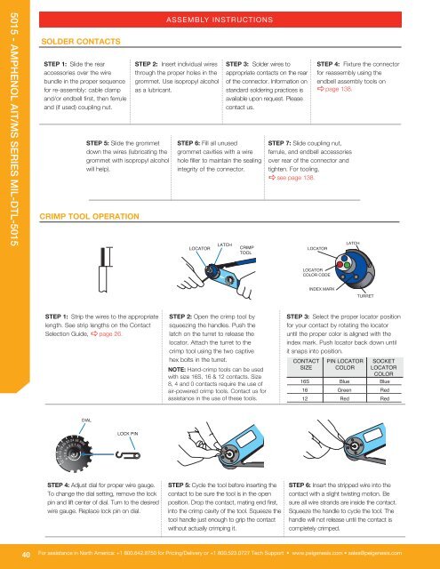
SOLDER CONTACTSSTEP 1: Slidethe rea
- Page 111 and 112:
INSERTION OF CONTACTS (CONTINUED)UN
- Page 113 and 114:
AIBC/ACA-B SERIES CONNECTORSSERIESA
- Page 115 and 116:
AMPHENOL HOW TO ORDER GUIDEVG95234
- Page 117 and 118:
Amphenol PT/PT-SE MIL-DTL-26482 Ser
- Page 119 and 120:
TECHNICALSPECIFICATIONSInsulation S
- Page 121 and 122:
STEP 3: SELECT LAYOUTCONTACTSROTATI
- Page 123 and 124:
STEP 3: SELECT LAYOUTCONTACTSINSERT
- Page 125 and 126:
CONTACT LEGEND = 20 =16 =HV =12 =co
- Page 127 and 128:
WIRE HOLE FILLERPIN & SOCKET CRIMP
- Page 129 and 130:
PIN & SOCKET SE CRIMP COAX CONTACTS
- Page 131 and 132:
PRINTED CIRCUIT BOARDHOW-TO-ORDER P
- Page 133 and 134:
ENDBELL STYLESL1DIMENSIONSA E F/SR
- Page 135 and 136:
DIMENSIONSSTRAIGHT PLUGSRIGHT ANGLE
- Page 137 and 138:
MS3057-C WATERPROOF CABLE CLAMPGASK
- Page 139 and 140:
INSERTION OF CONTACTSSTEP 1: Slide
- Page 141 and 142:
Amphenol 62GB SeriesMIL-DTL-26482 P
- Page 143 and 144:
TECHNICALSPECIFICATIONSInsulation S
- Page 145 and 146:
STEP 2: SELECT LAYOUTINSERT SERVICE
- Page 147 and 148:
SHELL†CHOOSE KEYWAY ORIENTATIONSV
- Page 149 and 150:
ENDBELL STYLES62GB10A62GB11ADIMENSI
- Page 151 and 152:
STRAIGHT PLUG STYLES62GB16P62GB16JD
- Page 154 and 155:
26482 - AMPHENOL 62GB SERIESRECEPTA
- Page 156 and 157:
26482 - AMPHENOL 62GB SERIESPINSCRI
- Page 158 and 159:
26482 - AMPHENOL 62GB SERIESSTEP 1:
- Page 160 and 161:
26482 - AMPHENOL 62GB SERIESINSERTI
- Page 162 and 163:
26482 - AMPHENOL MIL-DTL-26482 SERI
- Page 164 and 165:
26482 - AMPHENOL MIL-DTL-26482 SERI
- Page 166 and 167:
26482 - AMPHENOL MIL-DTL-26482 SERI
- Page 168 and 169:
26482 - AMPHENOL MIL-DTL-26482 SERI
- Page 170 and 171:
26482 - AMPHENOL MIL-DTL-26482 SERI
- Page 172 and 173:
26482 - AMPHENOL MIL-DTL-26482 SERI
- Page 174 and 175:
38999 - LJT MIL-DTL-38999 SERIES IT
- Page 176 and 177:
38999 - LJT MIL-DTL-38999 SERIES IC
- Page 178 and 179:
38999 - LJT MIL-DTL-38999 SERIES IH
- Page 180 and 181:
38999 - LJT MIL-DTL-38999 SERIES IV
- Page 182 and 183:
38999 - LJT MIL-DTL-38999 SERIES IV
- Page 184 and 185:
38999 - LJT MIL-DTL-38999 SERIES IP
- Page 186 and 187:
38999 - LJT MIL-DTL-38999 SERIES IC
- Page 188 and 189:
38999 - LJT MIL-DTL-38999 SERIES IR
- Page 190 and 191:
38999 - LJT MIL-DTL-38999 SERIES IA
- Page 192 and 193:
38999 - LJT MIL-DTL-38999 SERIES IW
- Page 194 and 195:
38999 -AMPHENOL JT MIL-DTL-38999 SE
- Page 196 and 197:
38999 -AMPHENOL JT MIL-DTL-38999 SE
- Page 198 and 199:
38999 -AMPHENOL JT MIL-DTL-38999 SE
- Page 200 and 201:
38999 -AMPHENOL JT MIL-DTL-38999 SE
- Page 202 and 203:
38999 -AMPHENOL JT MIL-DTL-38999 SE
- Page 204 and 205:
38999 -AMPHENOL JT MIL-DTL-38999 SE
- Page 206 and 207:
38999 -AMPHENOL JT MIL-DTL-38999 SE
- Page 208 and 209:
38999 -AMPHENOL JT MIL-DTL-38999 SE
- Page 210 and 211:
38999 -AMPHENOL JT MIL-DTL-38999 SE
- Page 212 and 213:
38999 -AMPHENOL JT MIL-DTL-38999 SE
- Page 214 and 215:
38999 - AMPHENOL TV-CTV TRI-START M
- Page 216 and 217:
38999 - AMPHENOL TV-CTV TRI-START M
- Page 218 and 219:
38999 - AMPHENOL TV-CTV TRI-START M
- Page 220 and 221:
38999 - AMPHENOL TV-CTV TRI-START M
- Page 222 and 223:
38999 - AMPHENOL TV-CTV TRI-START M
- Page 224 and 225:
38999 - AMPHENOL TV-CTV TRI-START M
- Page 226 and 227:
38999 - AMPHENOL TV-CTV TRI-START M
- Page 228 and 229:
38999 - AMPHENOL TV-CTV TRI-START M
- Page 230 and 231:
38999 - AMPHENOL TV-CTV TRI-START M
- Page 232 and 233:
38999 - AMPHENOL TV-CTV TRI-START M
- Page 234 and 235:
38999 - AMPHENOL TV-CTV TRI-START M
- Page 236 and 237:
38999 - AMPHENOL TV-CTV TRI-START M
- Page 238 and 239:
38999 - AMPHE-LITE D38999 SERIES II
- Page 240 and 241:
38999 - AMPHE-LITE D38999 SERIES II
- Page 242 and 243:
38999 - AMPHE-LITE D38999 SERIES II
- Page 244 and 245:
38999 - AMPHE-LITE D38999 SERIES II
- Page 246 and 247:
38999 - AMPHE-LITE D38999 SERIES II
- Page 248 and 249:
38999 - AMPHE-LITE D38999 SERIES II
- Page 250 and 251:
38999 - AMPHE-LITE D38999 SERIES II
- Page 252 and 253:
38999 - AMPHE-LITE D38999 SERIES II
- Page 254 and 255:
38999 - AMPHE-LITE D38999 SERIES II
- Page 256 and 257:
38999 - AMPHENOL SJT MIL-DTL-38999
- Page 258 and 259:
38999 - AMPHENOL SJT MIL-DTL-38999
- Page 260 and 261:
38999 - AMPHENOL SJT MIL-DTL-38999
- Page 262 and 263:
38999 - AMPHENOL SJT MIL-DTL-38999
- Page 264 and 265:
38999 - AMPHENOL SJT MIL-DTL-38999
- Page 266 and 267:
38999 - AMPHENOL SJT MIL-DTL-38999
- Page 268 and 269:
38999 - AMPHENOL SJT MIL-DTL-38999
- Page 270 and 271:
38999 - AMPHENOL SJT MIL-DTL-38999
- Page 272 and 273:
38999 - AMPHENOL SJT MIL-DTL-38999
- Page 274 and 275:
38999 - AMPHENOL SJT MIL-DTL-38999
- Page 276 and 277:
38999 - AMPHENOL SJT MIL-DTL-38999
- Page 278 and 279:
AMPHENOL AMPHE-EX EXPLOSION PROOF S
- Page 280 and 281:
AMPHENOL AMPHE-EX EXPLOSION PROOF S
- Page 282 and 283:
AMPHENOL AMPHE-EX EXPLOSION PROOF S
- Page 284 and 285:
AMPHENOL AMPHE-EX EXPLOSION PROOF S
- Page 286 and 287:
AMPHENOL AMPHE-EX EXPLOSION PROOF S
- Page 288 and 289:
AMPHENOL AMPHE-EX EXPLOSION PROOF S
- Page 290 and 291:
AMPHENOL AMPHE-EX EXPLOSION PROOF S
- Page 292 and 293:
AMPHENOL AMPHE-EX EXPLOSION PROOF S
- Page 294 and 295:
AMPHENOL AMPHE-EX EXPLOSION PROOF S
- Page 296 and 297:
AMPHENOL AMPHE-EX EXPLOSION PROOF S
- Page 298 and 299:
AMPHENOL SCE2/TERRAPIN SERIESRECEPT
- Page 300 and 301:
AMPHENOL SCE2/TERRAPIN SERIESINSERT
- Page 302 and 303:
AMPHENOL SCE2/TERRAPIN SERIESDIMENS
- Page 304 and 305:
AMPHENOL SCE2/TERRAPIN SERIESDIMENS
- Page 306 and 307:
AMPHENOL SCE2/TERRAPIN SERIESRECOMM
- Page 308 and 309:
2M SERIESTECHNICALSPECIFICATIONSMAT
- Page 310 and 311:
2M SERIESLAYOUTS BY NUMBER OF CONTA
- Page 312 and 313:
2M SERIESCREATE YOUR PART NUMBER 2M
- Page 314 and 315:
2M SERIESPLUGMASTERKEYB THREAD2M801
- Page 316 and 317:
2M SERIESSQUARE FLANGED GASKETSE RA
- Page 318 and 319:
2M SERIESCREATE YOUR PART NUMBER 2M
- Page 320 and 321:
2M SERIESPLUG2M803 DIMENSIONS BAYON
- Page 322 and 323:
2M SERIES2 HOLE FLANGED GASKETSC MA
- Page 324 and 325:
2M SERIESCREATE YOUR PART NUMBER 2M
- Page 326 and 327:
2M SERIESPLUGKEYA DIA.2M804 DIMENSI
- Page 328 and 329:
2M SERIES2M804 ACCESSORIESSHRINK BO
- Page 330 and 331:
2M SERIESCREATE YOUR PART NUMBER 2M
- Page 332 and 333:
2M SERIESPLUG2M805 DIMENSIONS2M805-
- Page 334 and 335:
2M SERIESSQUARE FLANGED GASKETSE RA
- Page 336 and 337:
2M SERIESPINSCONTACT TOOLSInsert he
- Page 338 and 339:
2M SERIESTURNAROUND ON CONNECTORS
- Page 340 and 341:
RJ FIELD SERIESRJF RB - REVERSE BAY
- Page 342 and 343:
RJ FIELD SERIESRJF 544 SERIESMAIN C
- Page 344 and 345:
RJ FIELD SERIESRJFMAIN CHARACTERIST
- Page 346 and 347:
RJRJ FIELD SERIESPLUGRJF 6Plug with
- Page 348 and 349:
RJ FIELD SERIESRJFTVMAIN CHARACTERI
- Page 350 and 351:
RJ FIELD SERIESPLUGRJF TV 6Plug wit
- Page 352 and 353:
RJ FIELD SERIESRJFTV - WITH 360° E
- Page 354 and 355:
RJ FIELD SERIESUSBFTV - USB-AMAIN C
- Page 356 and 357:
RJ FIELD SERIESPLUGUSBFTV 6USBFTV U
- Page 358 and 359:
RJ FIELD SERIESUSBBFTV - USB-BMAIN
- Page 360 and 361:
RJ FIELD SERIESUSBFTV SC - SPRING-L
- Page 362 and 363:
RJ FIELD SERIESREINFORCED USBFTVENV
- Page 364 and 365:
44 SERIESAmphenol-Tuchel Electronic
- Page 366 and 367:
ECO-MATEAmphenol EcomateEXCELLENT F
- Page 368 and 369:
ACCESSORIESSEALING SCREWSSealing sc
- Page 370 and 371:
ACCESSORIESRIGHT ANGLE HEAT SHRINK
- Page 372 and 373:
ACCESSORIESPOTTING SYSTEMACCESSORIE
- Page 374:
ACCESSORIESPMAFLEX PCSACCESSORIESPM