Amphenol Solutions Guide.pdf - Military Systems & Technology
Amphenol Solutions Guide.pdf - Military Systems & Technology
Amphenol Solutions Guide.pdf - Military Systems & Technology

You also want an ePaper? Increase the reach of your titles
YUMPU automatically turns print PDFs into web optimized ePapers that Google loves.
48 HOUR TURNAROUND ON CONNECTORSCONNECTORSOLUTIONS GUIDEHARSH ENVIRONMENTS • COMMERCIAL • INDUSTRIAL • MILITARY
WHO WE AREYOUR GLOBAL AMPHENOL DISTRIBUTORPEI-Genesis is one of the world’s fastest assemblers of precision connectors andpower supplies. From one of the largest component inventories, we delivery on timeand to your requirements. Our global technical support staff is available to help solveyour design challenges. PEI-Genesis can build over twelve million unique connectorsfrom stock at a rate of more than 5,000 per hour. Using proprietary automation forspeed, consistency, and quality, we can build just one piece or 10,000 pieces withequal ease; built to any standard or customized specification.PEI-Genesis is the only partner that offers assembly and shipment of connectors inforty-eight hours and power supplies in a week. Headquartered in Philadelphia, PA,we have production facilities in South Bend, IN; Bensalem, PA; and Southampton,UK; as well as 27 sales offices in eight countries. Visit us online at www.peigenesis.com to learn more.THE PEI ADVANTAGEWhen it comes to the world of connectors and power supplies, there is a vast array of manufacturing options. Because these products are not the primarydriver in a design, they are typically considered late in the design cycle. That tendency, when coupled with long lead times, can cause a disproportionateshare of delays and aggravation.PEI-Genesis will solve your design challenges. We will save you time by allowing your engineering team to focus solely on critical design elements. We willengage with you early in the design cycle, give you access to engineers around the world, provide design tools and methodology, and bring world-classexpertise to your application requirements in order to accelerate your design cycle and offload a significant portion of the design effort.COMPREHENSIVE TECHNICAL SUPPORTOur engineers are ready to assist you online, by phone, or atyour site.North America: +1 800.642.8750Europe: +44 (0) 844 871 6060Email: techsupport@peigenesis.comOnline: visit www.peigenesis.com to complete a tech supportrequest form – responses guaranteed in 24 hours or lessAn Authorized SourcePEI-Genesis sells and assembles only fully-authorized products.Our product capabilities meet the highest military and industrialstandards for consistent quality, inspection, marketing & packaging.RoHSCALL FOR DETAILS
WARRANTY & PRODUCT SAFETY INFORMATIONLIMITED WARRANTY<strong>Amphenol</strong> manufactures some of the highest quality products available;however, these products are intended for use in strict accordance with thespecifications in this catalog.A. If any of the products in this catalog are electrical components, componentsthereof, or electrical connectors accessories, then the warranty terms set forth inthis subparagraph (a) apply to them. <strong>Amphenol</strong> Corporation, <strong>Amphenol</strong> Aerospaceand PEI-Genesis warrant each new product sold by <strong>Amphenol</strong> or PEI-Genesis tobe free from defects in materials and workmanship under normal use and service.The obligation and liability of <strong>Amphenol</strong> and PEI-Genesis under this warranty islimited to the repair or replacement at its factory, at the option of <strong>Amphenol</strong> orPEI-Genesis, of any such product which proves defective within ninety (90) daysafter delivery to the first end user, and is found to be defective in materials andworkmanship by <strong>Amphenol</strong> inspection. Neither <strong>Amphenol</strong> nor PEI-Genesis shallbe obligated or liable under this warranty for apparent defects which examinationdiscloses are due to tampering, misuse, abuse, neglect, improper storage, normalwear and tear and all cases where the products are disassembled by otherthan authorized <strong>Amphenol</strong> or PEI-Genesis representatives. In addition, neither<strong>Amphenol</strong> nor PEI-Genesis shall be obligated or liable under this warranty unlessthe date of delivery to the first end user is within six (6) months of the date ofdelivery to the original purchaser, if different from the first end user, and furtherprovided that written notice of any defect must be given to <strong>Amphenol</strong> orPEI-Genesis within thirty (30) days from the date such defect is first discovered.Products covered by this warranty must be returned with all transportationcharges prepaid to <strong>Amphenol</strong> Corporation, <strong>Amphenol</strong> Aerospace or PEI-Genesisin shipping containers that are adequate to prevent loss or damage in shipment.Products repaired or replaced under this warranty are warranted for the unexpiredportion of the original warranty or for thirty (30) days, whichever is greater.PRODUCT SAFETY INFORMATIONThis information sheet should be read in conjunction with the Product Data Sheet/Catalog distributed by PEI-Genesis. Failure to observe the advice in thisinformation sheet and the operating conditions specified in the Product Data Sheet/Catalog could result in hazardous situations. None of the connectors in this catalog aremeant to be mated or unmated under load.1. MATERIAL CONTENT AND PHYSICAL FORMElectrical connectors do not usually contain hazardous materials. They containconducting and nonconducting materials and can be divided into two groups:a) Printed circuit types and low cost audio types which employ all plasticinsulators and casings; andb) Rugged, Fire Barrier and High Reliability types with metal casings and eithernatural rubber, synthetic rubber, plastic or glass insulating materials.Contact materials vary with type of connector and application and are usuallymanufactured from copper alloys, nickel, alumel, chromel or steel. In specialapplications, other alloys may be specified.2. FIRE CHARACTERISTICS AND ELECTRIC SHOCK HAZARDThere is no fire hazard when the connector is correctly wired and used within thespecified parameters.Incorrect wiring or assembly of the connector or careless use of metal tools orconductive fluids, or transit damage to any of the component parts may causeelectric shock or burns. Live circuits must not be broken by separating matedconnectors as this may cause arcing, ionization and burning.Heat dissipation is greater at maximum resistance in a circuit. Hot spots mayoccur when resistance is raised locally by damage, e.g., cracked or deformedcontacts, or broken strands of wire. Local overheating may also result from theuse of incorrect application tools or from poor quality soldering or slack screwterminals. Overheating may occur if the ratings in the Product DataSheet/Catalog are exceeded and can cause breakdown of insulation and, hence,electric shock.If heating is allowed to continue, it intensifies by further increasing the localresistance through loss of temper of spring contacts, formation of oxide film oncontacts and wires, and leakage currents through carbonization of insulationand tracking paths. Fire can then result in the presence of combustiblematerials and this may release noxious fumes. Overheating may not be visuallyapparent. Burns may result from touching overheated components.3. HANDLINGCare must be taken to avoid damage to any component parts of electricalconnectors during installation and use. Although there are normally no sharpedges, care must be taken when handling certain components to avoid injuryto fingers.Electrical connectors may be damaged in transit to customers and suchdamage may result in creation of hazards. Products should therefore beexamined prior to installation or use and rejected if found to be damaged inany respect.B. The purchaser’s SOLE AND EXCLUSIVE REMEDY, and the SOLE OBLIGATIONof <strong>Amphenol</strong> and PEI-Genesis, under the foregoing warranty shall be to repairor replace any defective or nonconforming products, provided that <strong>Amphenol</strong> orPEI-Genesis may, in their sole discretion, elect instead to refund the purchaseprice of the affected products. All replaced products shall become the property of<strong>Amphenol</strong> or PEI-Genesis.C. AMPHENOL AND PEI-GENESIS EXPRESSLY DISCLAIM ANY LIABILITY,WHETHER UNDER THIS WARRANTY OR OTHERWISE, FOR ANY FAILURE OFANY PRODUCT WHICH IS CAUSED, IN WHOLE OR IN PART, BY THE USE OFTHAT PRODUCT WITH OR IN ANY COMPONENT PARTS THAT WERE NOTMANUFACTURED BY AMPHENOL.D. THE ABOVE WARRANTY IS IN LIEU OF AND EXCLUDES ALL OTHERWARRANTIES, EXPRESS OR IMPLIED, INCLUDING BUT NOT LIMITED TO THEWARRANTIES OFMERCHANTABILITY AND FITNESS FOR A PARTICULAR PURPOSE, USE ORAPPLICATION, AND ALL OTHER OBLIGATIONS OR LIABILITIES ON THE PARTOF AMPHENOL ORPEI-GENESIS.E. THE AGGREGATE LIABILITY OF AMPHENOL AND PEI-GENESIS TO ANYPURCHASER IN DAMAGES OR OTHERWISE SHALL NOT EXCEED THEAGGREGATE PURCHASE PRICE OF THE PRODUCTS THAT ARE THE SUBJECTOF THE CLAIM OR DISPUTE. IN NO EVENT SHALL AMPHENOL OR PEI-GENESIS BE LIABLE FOR ANY INCIDENTAL, INDIRECT,CONSEQUENTIAL, PUNITIVE OR SPECIAL LOSSES OR DAMAGES OF ANYKIND,HOWSOEVER CAUSED. All such damages are expressly excluded anddisclaimed, it being understood that the products sold to the purchaser are notconsumer products. No action, regardless of form, arising out of, or in any wayconnected with any products furnished by PEI-Genesis may be brought by apurchaser more than one (1) year after the cause of action accrued.4. DISPOSALDispose of all products properly. The incineration of some products may releasenoxious or even toxic fumes.5. APPLICATIONConnectors with exposed contacts should not be selected for use on the currentsupply side of an electrical circuit, because an electric shock could result fromtouching exposed contacts on an unmated connector. Voltages in excess of30 Vac or 42.5 Vdc are potentially hazardous and care should be taken to ensurethat such voltages can not be transmitted in any way to exposed metal parts ofthe connector body. The connector and wiring should be inspected, before makinglive, to ensure there is no damage to metal parts or insulators, no solder blobs,loose strands, conducting lubricants, swarf, or any otherundesired conducting particles. Circuit resistance and continuity checks shouldbe made to make certain that there are no low resistance joints or spuriousconducting paths. Always use the correct application tools as specified in the DataSheet/Catalog.Do not permit untrained personnel to wire, assemble or tamper withconnectors. For operation voltage please see appropriate national regulations.IMPORTANT GENERAL INFORMATION1. AIR AND CREEPAGE PATHS/OPERATING VOLTAGEThe admissible operating voltages depend on the individual applications, andthe valid national and other applicable safety regulations. For this reason, the airand creepage path data are only reference values. Observe reduction of air andcreepage paths due to PC board and/or harnessing.2. TEMPERATUREAll information given are temperature limits. The operating temperature depends onthe individual application.3. OTHER IMPORTANT INFORMATION<strong>Amphenol</strong> and PEI-Genesis continuously endeavor to improve products.Therefore, products may deviate from the description, technical data orspecifications and/or shape as shown in this catalog. <strong>Amphenol</strong> andPEI-Genesis reserve the right to change the description, technical data orspecifications and/or shape of any products at any time.4. HARNESSING AND ASSEMBLY INSTRUCTIONSIf applicable, our special harnessing and/or assembly instruction must beadhered to. - This information can be provided on request.For assistance in Europe, please see the back cover for a complete listing of our branch offices and contact numbers.Specifications subject to change.1WARRANTY & PRODUCT SAFETY INFORMATION
SELECTING THE SERIES TO MEET YOUR NEEDS97 SERIESThe 97 series is a durable, cost-effective MIL-DTL-5015available in a variety of shell styles, sizes, contacts, andlayouts. Contacts are silver-plated with pre-tinned soldercups. These circular connectors are excellent for industrialapplications including robotics, machine tools and welding.Features include: Low cost • Solder termination • Wide selectionof shell styles and insert patterns • Solid or split shell construction.AIT/MS SERIESThe MIL-DTL-5015 AIT/MS series is a cost-effective threadedcircular connector for use in harsh environments. These<strong>Amphenol</strong> connectors are sealed to withstand moisture,condensation, vibration and flash-over. Over 286 contactlayouts are available, in variations that allow for just power,just signal, or a mix of both contact types. Available in five mounting styles,nineteen shell sizes, and solder or crimp termination.Features include: Broad temperature range from -67°F to +257°F (-55°Cto +125°C) under extremely harsh conditions. • Rugged aluminum alloy shell• Solder, crimp, PC, Coax and thermocouple contacts available.MS3450 (944*) SERIESThe MIL-DTL-5015 Rear-Release Threaded MS3450Matrix® series uses rear-release crimp contacts withretention clip. These <strong>Amphenol</strong> connectors fill the gapbetween older MIL-DTL-5015s and the environmentaland higher-performance needs of new technologies. They are sealed towithstand moisture, condensation, vibration and flash-over. Over 165 contactlayouts are available, in variations that allow for just power, just signal, or amix of both contact types.Features include: Broad operating temperatures • Recommendedfor extreme conditions • Rugged shell is highly resistant to damageand corrosion • Wide range of wire gauges and current carrying capacity.62GB SERIES<strong>Amphenol</strong>’s 62GB series connectors are similar toMIL-DTL-26482 but with the advantage of keywayorientation to reduce mis-mating among multipleconnectors. They feature aluminum shells with brassor stainless steel options available. PEI-Genesis is the largest assembler of62GB connectors in the world.Features include: Rugged, machined connector shell • Environmentallysealed • Resistant to harsh environments • Wide variety of endbell styles.MB SERIES-DTL-26482 SERIES II<strong>Amphenol</strong>’s Matrix® MIL-DTL-26482 series II miniaturecylindrical connectors have a quick-mating, three-pointbayonet coupling system. Given their small size andhigh-quality contact retention and seal, the MB series isexcellent for high-reliability applications in the harshest conditions, includingthe aerospace industry.Features include: Total environmental sealing • Wide operating temperaturerange -85°F to +392°F (-65°C to +200°C) • Quick mating, three pointbayonet coupling •100% scoop proof shell design • EMI-RFI shielding, •Available in a rugged 500 hour salt spray plating.LJT MIL-DTL-38999 SERIES I/HE-308<strong>Amphenol</strong>’s MIL-DTL-38999 series I LJT miniatureconnectors offer high-density contact arrangements andare suitable for extremely high-reliability connections,including use in military and commercial aviation. Theyare environmentally-sealed and have a wide operatingtemperature range.Features include: Very small area for mating the connectors • Totalenvironmental sealing • Wide operating temperature range • Extremely lightweight connector design • Quick mating three point bayonet coupling • Widerange of receptacle styles • Available in a rugged 500 hour salt spray plating.AIB/GT SERIESThe AIB/GT Series replaces the threaded coupling used inMIL-DTL-5015 with a positive, quick-mating, three-pointreverse bayonet lock for improved performance. These<strong>Amphenol</strong> connectors are an ideal cost-effective optionfor applications requiring reliability in harsh environments, and is the worldstandardfor rail, mass transit, and military ground vehicle applications.This series has the same shell dimensions, contact layouts, contacts, andperformance characteristics as the MIL-DTL-5015 threaded connectors;however, the two series do not intermate. They are sealed to withstandmoisture, condensation, vibration and flash-over. Over 180 contact layoutsare available, in variations that allow for just power, just signal, or a mix ofboth contact types.Features include: Simple and fast mating and unmating. • Shock andvibration resistant • Proven reliability • Lightweight yet highly resistant todamage.PT MIL-DTL-26482 SERIES IThe <strong>Amphenol</strong> MIL-DTL-26482 Series I PT/PT-SE offershigh-density contact arrangements in a circular shell. PToffers solder contacts, PT-SE offers high-performance crimpcontacts, and PT-CE offers a commercial crimp option.These circular connectors provide quick-disconnect bayonet coupling forrapid mating and unmating, and several mounting styles and shell sizes.Features include: Rugged shell • Environmentally sealed• Resistant to military environments • Wide range of wire gaugesand current carrying capability.JT MIL-DTL-38999 SERIES I/HE-308<strong>Amphenol</strong>’s MIL-DTL-38999 series I LJT miniatureconnectors offer high-density contact arrangements andare suitable for extremely high-reliability connections,including use in military and commercial aviation. Theyare environmentally-sealed and have a wide operatingtemperature range.Features include: Very small area for mating the connectors • Totalenvironmental sealing • Wide operating temperature range • Extremely lightweight connector design • Quick mating three point bayonet coupling • Widerange of receptacle styles • Available in a rugged 500 hour salt spray plating.TV-CTV MIL-DTL-38999 SERIES IIITV-CTV Tri-Start MIL-DTL-38999 Series III connectorshave high-density contact arrangements in a miniaturecircular shell. Originally designed for the high-performancerequirements of military and commercial aircraft, thesecircular connectors are perfect for applications requiring extremely reliableinterconnections. TV’s are quick-mating and environmentally-sealed.Features include: Total environmental sealing • Wide operating temperaturerange • quick mating, triple lead threaded, self-locking coupling •100%scoop proof shell design • EMI-RFI shielding, • Available in a rugged 500hour salt spray plating or 1000 hour salt spray material.2For assistance in North America: +1 800.642.8750 for Pricing/Delivery or +1 800.523.0727 Tech Support • www.peigenesis.com • sales@peigenesis.com
AMPHE-LITE<strong>Amphenol</strong>’s MIL-DTL-38999 series III Amphe-Liteconnectors are light-weight commercial 38999s thatoffer the highest performance capabilities for harshenvironments, including communication towers andequipment, manufacturing process control and medical equipment.Features include: Amphelite connectors perform flawlessly under widetemerature ranges, high vibrations and are resistant to a vast array ofcontaminants. • Outstanding EMI Sheilding Protection – up to 50dBminimum-100Mhz to 10GHz • Operates at extreme temperatures(from -67°F up to 320°F (-55°C up to +150°C )SJT/JN1003 SERIES<strong>Amphenol</strong>’s SJT series of miniature MIL-DTL-38999series II circular connectors offer high-density contactarrangements. They are environmentally-sealed and have awide operating temperature range.Features include: Total environmental sealing • Wide operating temperaturerange • quick mating, three point bayonet coupling • Scoop proof shelldesign • EMI-RFI shielding available • Available in a rugged 500 hour saltspray plating.AMPHE-EX<strong>Amphenol</strong> Industrial’s explosion-proof connector seriesAmphe-EX is ATEX and IECex-approved for Zone1-rated (Europe) and Class I, Division II (USA) hazardousapplications (IECex 60079). Amphe-EX is the only explosion-proof connectorthat allows the use of copper, coax and fibre optic contacts in one product.PEI-Genesis is the only approved worldwide assembling distributor.Features include: Equipped to handle signal, power, RF or fiber opticrequirements • Insert patterns ranging from 2#20 contacts up to 79#22Dcontacts • High tensile strength aluminum plated in a hard anodic platingscratch resistant coating to MIl-A-8625, Type III.SCE2 TERAPIN SERIES<strong>Amphenol</strong>’s SCE2 Terrapin series of miniature push-pullconnectors are environmentally-sealed for use in harshenvironments. They offer silent mating with high matingcycles and a lockable coupling ring to prevent connectorbreak-away. For more product details, please see fullspecifications below.Features include: Non-magnetic • RoHS compliant • Copper Alloy contactmaterial2M SERIES<strong>Amphenol</strong> 2M micro-miniature connectors are a small, lightweightoption for mil-spec performance that can withstandharsh environments. They are quick-mating and a variety ofstyles and options are available. For full product details, pleasesee our specifications below.Features include: Smaller, lighter-weight alternative for D38999performanceRJ FIELD SERIESThe <strong>Amphenol</strong> RJ Field series allows the use of anEthernet Class D/Cat5e and Class E/Cat6 connection forEthernet over twisted-pair networks in harsh environments.The RJStop® connection system protects from shock,dust and fluid. No hazardous on-field cabling and grounding required!Features include: Full environmental sealing • Easy to assemble • Vibrationresistant mating system44 SERIES<strong>Amphenol</strong> Tuchel 44 series connectors offer cost-effectiveperformance for applications requiring environmentalsealing. The connector’s single-piece structure is resistantto water, fuel, lubricants, ozone, road salt and vibration.Features include: Protection against mismating • 3liquid proof seals (primary, secondary, and wire) • Quck and easy assembly• Discrete wire interconnectionC 091 SERIESThe <strong>Amphenol</strong>-Tuchel C091 series connectors areavailable in a variety of contact arrangements and have ametal integral strain relief. They are available in straight orright-angle configurations.Features include: Available with crimp solder or PCBterminals • Front or rear mounting receptacles • EMI shielded fully mated onA&D types • Internal strain reliefECO-MATE<strong>Amphenol</strong> Ecomate connectors are ruggedand offer environmental protection under eventextreme conditions. They are excellent for plantconstruction, machine building, control technologyand medical applications. A wide selection ofhousings and shapes are available.Features include: Quick and easy to assemble • Housing material madefrom premium molding material • Screwed cable gland with clamping ring •Cable housing straight or angledALDEN PRODUCTS<strong>Amphenol</strong> Alden Pulse-Lok® connectors have aunique locking coupling system with both tactile andaudible confirmation for secure connections as well asquick-release action. These connectors are excellentfor medical, factory automation, and instrumentationfield applications. Many contact types are available, including signal,power, high-voltage, and Ethernet.Features include: Quick release action • Small package (.500 — 1.2”diameter) • Tactile confirmation • 1 to 78 conductiorsFor assistance in Europe, please see the back cover for a complete listing of our branch offices and contact numbers.Specifications subject to change.3
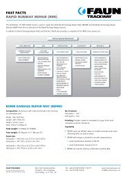
5015 Series97 AIT/MS MS3450 AIB/GTCONNECTOR SERIESCOMPARISON CHARTConnector cost generallyincreases across the tablefrom left to right.REVIEW THE BASIC TYPES• Industrial/commercial connectorsgenerally do not need to operate inextreme conditions• Harsh environment connectors are generallyused in harsh and/or outdoor applications.• <strong>Military</strong> connectors will meet different milspecifications.Industrial/Commercial • • • •Harsh Environment • • •<strong>Military</strong> • •Wire Gauge Range (AWG) 26 to 0 26 to 0 20-0 26 to 0Number of Circuits 1 to 52 1 to 85 1 to 85 1 to 85Sealed Against Water Jets No Yes Yes YesEMI/RFI-Shielding Yes Yes Yes YesStyle Circular Circular Circular CircularOperating Voltage/ DWV 1,750 Vac 3,000 Vac 3,000 Vac 3,000 VacCurrent Rating (Amps) 150 150/245 150/245 150/245Power & Signal on SameLayoutYes Yes Yes YesOperating Temperature-67°F to 257°F-55°C to125°C-67°F to 257°F-55°C to125°C-75°F to 392°F-55°C to 200°C-67°F to 257°F-55°C to125°CSubmersible No Yes Yes YesIndividual Wire Sealing No Yes Yes YesCable Jacket Sealing Yes Yes No YesType of Coupling Threaded Threaded Threaded Reverse BayonetLife in Mating Cycles (min.) 100 100 100 500/2,000Shock Test (g’s) 50 50 50 50Vibration Test (grms) 15 15 15 15Susceptibility to Damage Very Low Very Low Very Low Very LowSTART WITH THESE FOUR VARIABLES:1. Determine wire gauge range-Will indicate connector size2. Determine required number of circuits-Generally, more circuits means a larger andmore expensive connector3. Determine if water-jet sealing is necessary-Choices include submersible, individual wiresealing and cable jacket sealing4. Determine if EMI-RFI Shielding is required-Does your connection need protection frominterfering signals? Generally, thisrequirement sparates economical connectorsfrom mid-range costBy answering these questions and using theinformation on this chart, you should identifythe series that will fit your needs.Please visit our Web site for an interactivecomparison and selection guide featuring ourentire line of <strong>Amphenol</strong> connectors.Shell Material Aluminum Alloy Aluminum Alloy Aluminum Alloy Aluminum AlloyShell PlatingShell ColorAnodizedElectrolessNickel,or Zinc AlloyOlive Drab,Silver,or BlackCadmium,Anodized,Electroless Nickel,or Zinc AlloyOlive Drab, Silver,or BlackCadmium,Anodized,ElectrolessNickel,or Zinc AlloyOlive Drab,Silver,or BlackBlack Anodize,ElectrolessNickel, Cadmium,or PassivatedCadmium,Olive Drab,Silver,or BlackPositive Shell Polarization Yes Yes Yes YesInsert Polarization Options Yes Yes Yes YesUser Polarization Yes No No NoStandards/AssociatedSpecs.MIL-DTL-5015UL #E115497CSA LR 69183MIL-DTL-5015MIL-DTL-5015MIL-DTL-5015UL #E115497VG95234Contact Plating Silver or Gold Silver or Gold Silver or Gold Silver or GoldContact StylesCrimp • • •Solder • • •Printed Circuit Solder • • •Printed Circuit Press fitThermocoupleWire WrapCo-AxInsulation Displacement orScrewPre TerminatedFiber OpticHigh VoltageFirst-Mate Last-Break4For assistance in North America: +1 800.642.8750 for Pricing/Delivery or +1 800.523.0727 Tech Support • www.peigenesis.com • sales@peigenesis.com
26482 Series 38999 SeriesPT/PTSE 62GB MB LJT/HE308 JT TV-CTV Amphe-Lite SJT/JN1003• •• • • • • • • •• • • • • • •24 to 12 24 to 8 24 to 12 24 to 12 28 to 12 28 to 12 28 to 8 28 to 121 to 61 2 to 61 3 to 61 3 to 128 3 to 128 3 to 128 2 to 128 3 to 128Yes Yes Yes Yes Yes Yes Yes YesYes Yes Yes Yes Yes Yes Yes YesCircular Circular Circular Circular Circular Circular Circular Circular1,000 Vac/5kv 1,500 Vac 2,300 Vac 2,300 Vac 2,300 Vac 2,300 Vac 2,300 Vac 2,300 Vac23 22 23 1.5 to 23 1.5 to 23 1.5 to 46 1.5 to 46 1.5 to 23Yes Yes Yes Yes Yes Yes Yes Yes-67°F to 257°F-55°C to125°C-67°F to 257°F-55°C to125°C-67°F to 392°F-55°C to200°C-67°F to 392°F-55°C to200°C-67°F to 392°F-55°C to200°C-67°F to 392°F-55°C to200°C-67°F to 248°F-55°C to 125°C-67°F to 392°F-65°C to 200°CYes Yes Yes Yes Yes Yes Yes YesYes Yes Yes Yes Yes Yes Yes YesYes Yes Yes Yes Yes Yes Yes YesBayonet Bayonet Bayonet Bayonet Bayonet Threaded Threaded Bayonet500 500 500 500 500 500/1500 500 50050 100 150 300 300 300 - 30015 10 20 49.5 43.7 60 - 49.5Very Low Very Low Extra Low Extra Low Extra Low Extra Low Very Low Extra LowAluminum AlloyAluminum Alloy,Marine Alloy,Stainless SteelAluminum Alloy Aluminum Alloy Aluminum AlloyAluminum Alloy,Stainless Steel,Marine NickelAlum. Bronze orCompositeCompositeAluminium AlloyCadmium,Anodized,Electroless Nickel,or Zinc AlloyCadmium,Anodized,Electroless Nickel,or Zinc AlloyCadmium, orElectroless NickelCadmium,Electroless Nickel,or AnodizedCadmium,Electroless Nickel,or AnodizedCadmium,Electroless Nickel,Anodized, orAluminum BronzeCadmium, orElectroless NickelCadmium,Electroless Nickel,Anodized or ZincCobaltOlive Drab, Silver,or BlackOlive Drab, Silver,or BlackOlive Drab, orSilverOlive Drab, Silver,or BronzeOlive Drab, Silver,or BronzeOlive Drab, Silver,or BronzeOlive Drab, Silver,or BlackOlive Drab, Silver,or BronzeYes Yes Yes Yes Yes Yes Yes YesYes Yes Yes Yes Yes Yes Yes YesNo No No No No No No NoMIL-DTL-26482Series IUL #E115497BS9522 F00 17MIL-DTL-26482Series IIMIL-DTL-38999Series IMIL-DTL-38999Series IMIL-DTL-38999Series IIIUL E115497 -Gold Gold Gold Gold Gold Gold Gold Gold• • • • • • • •• •• • • • • • • •• • • • • • •• • • • • • •• • • • • ••For assistance in North America: +1 800.642.8750 for Pricing/Delivery or +1 800.523.0727 Tech Support • www.peigenesis.com • sales@peigenesis.com 5
Amphe-EX RJ Field SCE2 2M 44 Series Eco-Mate C091 Alden• • • • • • • •• • • • •• •28 to 8 CAT5/SE 24 to 30 20 to 12 14 to 18 26 to 14 18 to 26 26 to 122 to 79 2 to 79 7 to 37 1 to 130 1 to 6 4 to 7 3 to 14 1 to 78Yes Yes Yes Yes Yes Yes Yes YesYes Yes Yes Yes No No Yes YesCircular Circular Circular Circular Circular Circular Circular Circular2,300 Vac - 400 Vac 1800 Vac 250 Vac 400V/250 Vac 250 Vac/60 Vac 300 Vac1.5 to 46 - 23 20 8A 10 to 16 3 to 5 2 to 20Yes No Yes Yes Yes Yes Yes Yes-47°F to 104°F-20°C to 40°C-40°F to 185°F-40°C to 85°C-67°F to 248°F-55°C to 125°C-67°F to 392°F-55°C to 200°C-40°F to 221°F-40°C to 105°C-40°F to 212°F-40°C to 100°C-40°F to 185°F-40°C to 85°C -20°C to 150°CYes Yes Yes Yes Yes Yes Yes YesYes No No Yes Yes No No NoYes Yes Yes Yes No Yes Yes YesThreadedPush-Pull, Bayonet,Triple-LeadThreadedPush-PullPush-PullBayonetTriple & Dual-LeadThreadedFriction-FitThreadedThreaded orBayonet500 500 200 250/2000 25 (Max) 500 1000 5000300 250 100 300 - - - -60 10 10 37 - - - -Extra Low Very Low Very Low Extra Low Medium Very Low Very Low LowPulse-LokAluminium Alloy,Brass, or StainlessSteelThermoplastic,AluminiumAluminum AlloyAluminum AlloyStanoprene.thermpastic rubberPA6.6/PA6Die CastThermoplastic orBrassAnodizedCadmium,Anodized, orElectroless NickelBlack-SilverBlack Anodized,Electroless Nickel,Cadium, PassivatedBlack, Olive Drab,Zinc, NickelNone None Nickel Nickel-PlatedBlackOlive Drab, Silver,or BlackBlack MatteOlive Drab, Silver,or BronzeBlack Black & Blue Silver Black or SilverYes Yes Yes Yes No No No YesYes Yes Yes Yes No No No NoNo Yes No No No No No No- - - - -VDE1781, 1780:SEV00.00394:UL E63093: CSA UL E63093 -48932: GermanLloyd 14108/84Gold Gold Gold Gold Tinned Silver or Gold Silver Gold• • • • • •• • • •• • ••••• • •• •• •6For assistance in Europe, please see the back cover for a complete listing of our branch offices and contact numbers.Specifications subject to change.
TABLE OF CONTENTS97 Series5015 SeriesDescription, Applications and Features. ............................. 9Technical Specifications. ........................................ 9Components ................................................ 11Create Your Part Number. ................................... 12-13Dimensions. .............................................. 14-16Accessories. ............................................. 17-19Assembly Instructions. ......................................... 20AIT/MS SeriesDescription, Applications and Features. ............................ 21Technical Specifications. .................................... 22-23Create Your Part Number. ................................... 24-25Pin & Socket Crimp Contacts. ................................ 26-27Pin & Socket Coax Contacts ................................. 28-29Dimensions. .............................................. 30-35Pre-Earth Series/FMLB. ........................................ 36Accessories. ............................................. 37-39Assembly Instructions. ...................................... 40-42How to Order <strong>Guide</strong> MS. ....................................... 43How to Order <strong>Guide</strong> AC. ....................................... 44MS3450 SeriesDescription, Applications and Features. ............................ 45Technical Specifications. .................................... 46-47Cross-Section ............................................... 47Create Your Part Number. ................................... 48-49Dimensions. .............................................. 50-51Pin & Socket Contacts/Tools. ................................ 52-53Panel Cutouts and Panel Thickness. .............................. 54Accessories. ................................................ 55Assembly Instructions. ......................................... 56AIB/GT SeriesDescription, Applications and Features. ............................ 57Technical Specifications. .................................... 58-61Cross Section. ............................................... 61Create Your Part Number. ................................... 62-63Layouts by Number of Contacts. .............................. 64-74Layouts by Shell Size. ...................................... 75-85Pin & Socket Crimp Contacts. ................................ 86-87Pin & Socket Coax Contacts ................................. 88-89Components ................................................ 90Dimensions. ............................................. 91-103Accessories. ........................................... 104-106Assembly Instructions. .................................... 107-109How to Order <strong>Guide</strong> GT. ...................................... 110How to Order <strong>Guide</strong> ACA-B. ............................... 111-113Connector Tools. ............................................ 114PT/PTSE26482 SeriesDescription, Applications and Features. ........................... 115Technical Specifications. .................................. 116-117Layouts by Number of Contacts. ............................ 118-121Contacts .............................................. 122-123Panel Cutouts. .......................................... 124-129Dimensions. ............................................ 130-134Accessories. ............................................... 135Assembly Instructions. .................................... 136-13762GBLJT/HE30826482 SeriesDescription, Applications and Features. ........................... 139Technical Specifications. .................................. 140-141Create Your Part Number. ................................. 142-143Layouts by Number of Contacts. ................................ 144Components ............................................... 145Dimensions. ............................................ 146-153Pin & Socket Crimp Contacts. .................................. 154Accessories. ............................................... 155Assembly Instructions. .................................... 156-158MBDescription, Applications and Features. ........................... 159Technical Specifications. .................................. 160-161Create Your Part Number. ................................. 162-163Layouts by Number of Contacts. ................................ 164Dimensions. ................................................ 165Contacts .............................................. 166-167Panel Cutouts and Panel Thickness. ............................. 168Accessories. ............................................... 169Assembly Instructions. ........................................ 17038999 SeriesDescription, Applications and Features. ........................... 171Technical Specifications. .................................. 172-173Create Your Part Number. ................................. 174-175How to Order HE308Series Connectors. ...................................... 176-177Layouts by Number of Contacts. ............................ 178-181Contacts .............................................. 182-185Dimensions. ............................................ 186-187Accessories. ........................................... 188-189Assembly Instructions. ........................................ 190JTDescription, Applications and Features. ........................... 191Technical Specifications. .................................. 192-193Create Your Part Number. ................................. 194-195Layouts by Number of Contacts. ............................ 196-198Tooling Accessories. ......................................... 199Contacts .............................................. 200-203Dimensions. ............................................ 204-207Accessories. ........................................... 208-209Assembly Instructions. ........................................ 210TV-CTVDescription, Applications and Features. ........................... 211Technical Specifications. .................................. 212-213Create Your PartNumber (<strong>Military</strong>) ........................................ 214-215Create Your PartNumber (Commercial). .................................... 216-217Layouts by Number of Contacts. ............................ 218-221Contacts/Contact Tools. .................................. 222-227Dimensions. ............................................ 228-230Tooling Accessories. ......................................... 231Accessories. ........................................... 232-233Assembly Instructions. ........................................ 234For assistance in North America: +1 800.642.8750 for Pricing/Delivery or +1 800.523.0727 Tech Support • www.peigenesis.com • sales@peigenesis.com7
TABLE OF CONTENTSAmphe-LiteAmpheExDescription, Applications and Features. ........................... 275Technical Specifications. .................................. 276-277Create Your Part Number. ................................. 278-279Layouts by Number of Contacts. ............................ 280-281Contacts/Contact Tools. .................................. 282-283Dimensions. ................................................ 284Dialight Products ............................................ 285Assembly Instructions. .................................... 286-290Hazardous Zone. ........................................ 291-294SCE2 Terrapin Series38999 SeriesDescription, Applications and Features. ........................... 235Technical Specifications. .................................. 236-237Create Your Part Number. ................................. 238-239Layouts by Number of Contacts. ............................ 240-243Contacts .............................................. 244-247Dimensions. ............................................ 248-249Accessories. ............................................... 250Assembly Instructions. ........................................ 251SJT/JN1003Description, Applications and Features. ........................... 253Technical Specifications. .................................. 254-255Create Your Part Number. ................................. 256-257How to Order JN1003Series Connectors. ...................................... 258-259Layouts by Number of Contacts. ............................ 260-263Contacts .............................................. 264-267Dimensions. ............................................ 268-271Accessories. ........................................... 271-273Assembly Instructions. ........................................ 274Explosion ProofSubminiature CircularDescription, Applications, Technical Specifications. .................. 295How To Order Receptacles/Plugs ........................... 296-297Insert Arrangements and Keyways. .............................. 298Dimensions. ............................................ 299-302Dimensions – Accessories. .................................... 303Wiring Assembly/Ethernet Wiring. ............................... 3042MDescription, Applications and Features. ........................... 305Technical Specifications. .................................. 306-307Layouts by Number of Contacts. ............................ 308-309How to Order JN1003Series Connectors. ...................................... 258-259Contacts .............................................. 264-267Dimensions. ............................................ 268-271Accessories. ........................................... 271-273Assembly Instructions. ........................................ 274RJ FieldEnvironmental EthernetDescription, Applications, Features and Technical Specifications. ....... 337RJF RB Reverse Bayonet. ................................. 338-339RJF 544 Series. ......................................... 340-344Self Closing Caps. ........................................... 345Cable Cat 5E. .............................................. 345RJFTV ................................................ 346-349RJFTV 360° . ........................................... 350-351USBFTV USB-A. ........................................ 352-354USBFTV USB-B ........................................ 355-357USBFTV SC How To Order ................................ 358-359Memory Keys. .......................................... 360-36144 SeriesTuchelDescription, Applications, Features,Technical Specifications, Part Numbers,and Contacts & Tooling. ...................................... 362C091 SeriesDescription, Applications,Features, Technical Specifications,and Approvals .............................................. 363Eco-MateDescription, Applications,Features, Technical Specifications,and Approvals .............................................. 364Alden ProductsMedicalDescription, Applications,Features, and Various Types ................................... 365AccessoriesSealing Screws. ............................................. 366Nut Plates ................................................. 366Standard Heat Shrink Boots. ................................... 367Right Angle Heat Shrink Boots. ................................. 368Black Polyolefin Convoluted Boots. .............................. 369Potting System (3M). ......................................... 370Heat Gun. ................................................. 370PMA Adapters. ............................................. 371PMAFLEX PCS. ............................................. 372F.CK Screening Braid. ........................................ 372AppendixGlossary. .............................................. 373-3828For assistance in Europe, please see the back cover for a complete listing of our branch offices and contact numbers.Specifications subject to change.
<strong>Amphenol</strong> 97 Series MIL-DTL-5015MATES WITH ALL THREADED MIL-DTL-5015CONNECTORSThe 97 series is a durable, cost-effective MIL-DTL-5015 available in a varietyof shell styles, sizes, contacts, and layouts. Contacts are silver-plated withpre-tinned solder cups. These circular connectors are excellent for industrialapplications including robotics, machine tools and welding.• UL-approved & CSA-certified• Also called MIL-C-5015 or MSNote: MS-A version (blue insulator) is inactive for new military designs. The 97 series can bepurchased under inactive military part numbers, so use caution. MIL-DTL-5015 uses a grayinsulator. Obsolete MS-A connectors can be purchased with the original hard blue insulator or thenewer sealed construction, using a soft neoprene insulator. For the neoprene insulator, add “-RES”as a suffix to the part number.APPLICATIONSIndustrial, commercial and medical applications where cost-effective, general-duty connectors are required.FEATURESTECHNICALSPECIFICATIONS• Communications systems• Conveyors• Factory automation• Industrial machinery• Cost-effective• Solder termination• UL-recognized and CSA-certifiedMATERIALS & FINISHESShellPlatingContactsPlatingsInsulator• Medical instrumentation• Motors• Mobile equipment• Sensors• Wide selection of shell stylesand insert patterns• Wide variety of connector finishesAluminum alloy• Ships• Trucks• Trailers• Threaded coupling,hard dielectric inserts• Solid or split-shellconstructionOlive drab chromate or clear chromate coating over cadmiumplating to QQ-P-416, Black zinc cobalt, electroless nickelor green zincBrass or copper alloySilver plating to QQ-S-365 (solder contacts have tinned solder pot)Gold plating to MIL-G-45204Diallyl phthalate (Blue color)For assistance in Europe, please see the back cover for a complete listing of our branch offices and contact numbers.Specifications subject to change.95015 - AMPHENOL 97 SERIES MIL-DTL-5015
5015 - AMPHENOL 97 SERIES MIL-DTL-5015TECHNICALSPECIFICATIONSELECTRICAL DATAOperating Voltage/Test VoltageSERVICERATING*TESTVOLTAGE(RMS 60 cps)SUGGESTED* OPERATING VOLTAGEDCAC (rms)AIR SPACINGNOM. (INCHES)CREEPAGEDISTANCENOM. (INCHES)I 1,000 250 200 1/32 1/16A 2,000 700 500 1/16 1/8D 2,800 1,250 900 1/8 3/16E 3,500 1,750 1,250 3/16 1/4B 4,500 2,450 1,750 1/4 5/16* Each insulator has a specific service rating. These numbers should be used by the designer only as aguide. The Service Ratings for each layout are listed on a pages 64-85.97 series connectors show no evidence of breakdown when the given test voltages are appliedbetween the two closest contacts and between the shell and the contacts closest to the shell fora period of one minute, per MIL-STD-1344 Method 3001.Current Rating & Contact ResistanceCONTACT SIZE TEST CURRENT (AMPS) POTENTIAL DROP (MILLIVOLTS)16 13 4912 23 428 46 264 80 230 150 21Maximum total current to be carried per connector in wire bundles as specified in MIL-W-5088.Contact resistance when tested to MIL-C-39029 will not exceed voltage drops listed in above table.MECHANICALWire Range SizesContact Resistance24 to 0 AWG(See table above)Insulation Resistance > 5,000 megohms at 77°F (25°C) per MIL-DTL-5015, 3.18Mating Life 100 cycles minimum per MIL-DTL-5015, 3.16Salt SprayHeatChemical ResistanceVibrationShockContact TypeMIL-STD-1344 Method 1001 Condition Bminimum (Cadmium) 48 hour+257˚F (+125˚C) for 60 hours, +185˚F (+85˚C) for1,000 hours per MIL-DTL-5015, 4.6.14, minimum20 hour full immersion (unmated) in hydraulic fluidand lubricating oil per MIL-DTL-5015 minimum10 to 2,000Hz (15g’s) 10 microsecondsmaximum discontinuity to MIL-STD-1344 Method2005 per MIL-DTL-501550g 11 millisecond duration, three major axes10 microseconds maximum discontinuityto MIL-DTL-5015, 3.13Solder (hard silver or gold plating)Number of Circuits 1 to 52 (aSee pages 64-85)10For assistance in North America: +1 800.642.8750 for Pricing/Delivery or +1 800.523.0727 Tech Support • www.peigenesis.com • sales@peigenesis.com
TECHNICALSPECIFICATIONSContact retention and separation forces to MIL-DTL-5015, 4.6.6 & 3.26 minimum.PolarizationApprovals/Agency ListingPLUGSRETENTION AXIAL LOADCOMPONENTSIntegral key and keyway plus optional rotationalpolarization. a See pages 75-85 for valid rotationsUL# EII5497; CSA LR69183 for 97 SeriesSEPARATION FORCE MINIMUMCONTACT SIZE NEWTONS LB NEWTONS LB16 44 10 1 0.2512 67 15 2 0.508 89 20 3 0.754 89 20 4 1.000 111 25 9 2.00RECEPTACLES5015 - AMPHENOL 97 SERIES MIL-DTL-5015Barrel/ShellCoupling Nut/SpringInsert AssemblyInsert Retainer SpringEndbellFor assistance in Europe, please see the back cover for a complete listing of our branch offices and contact numbers.Specifications subject to change.11
5015 - AMPHENOL 97 SERIES MIL-DTL-5015CREATE YOUR PART NUMBER USING THESE FIVE STEPSSTEP 1 2 3 4 597 3106A 18-1 P -946SERIESPREFIXSHELL STYLE LAYOUT CONTACT ROTATION PLATINGSTEP 1: SELECT SHELL STYLE, PLUG OR RECEPTACLERECEPTACLESMates withPLUGS(example)97-3100AWall Mount with AccessoryThreads, Solid Endbell97-3106AStraight with AccessoryThreads, Solid Endbell97-3106BStraight with AccessoryThreads, Split Endbell97-3101ACable Mount withAccessory Threads,Solid Endbell97-3107AFriction Fit Straightwith Accessory Threads,Solid Endbell97-3107BFriction Fit Straightwith Accessory Threads,Split Endbell97-3102ABox Mount with NoAccessory Threads97-3108ARight Angle with AccessoryThreads, Solid Endbell97-3108BRight Angle with AccessoryThreads, Split Endbell12For assistance in North America: +1 800.642.8750 for Pricing/Delivery or +1 800.523.0727 Tech Support • www.peigenesis.com • sales@peigenesis.com
8S-110SL-3*10SL-4*12-512S-112S-212S-312SL-84412-514S-114S-214S-414S-514S-614S-714S-914S-1014S-1114S-1214S-1314S-1416S-116S-416S-516S-616S-816S-1416S-1516S-1616S-1716SA1816SA1916SA2016SA2116-716-916-1016-1116-1216-1318A3118-118-318-418-518-818-918-1018-1118-1218-1318-1618-1718-1818-1918-2018-2218-2318-2418-2518-2618-2718-28* Socket for plug only. Pin for receptacle only.STEP 2: SELECT LAYOUTa See pages 64-85 for more information18-2918-3018-3118-42020A1620A3720-320-420-620-720-820-1120-1420-1520-1620-1720-1820-1920-2120-2320-2420-2520-2720-2920-3020-3220-3322-122-222-422-522-822-922-1022-1122-1222-1322-1422-1522-1622-1822-1922-2022-2222-2322-2722-2822-3022-3122-3222-3424-224-524-624-724-924-1024-1124-1224-1624-1924-2024-2124-2224-2424-2524-2624-2724-2828-128-228-328-628-828-928-1028-1128-1228-1328-1528-1628-1728-1828-1928-2028-2132-532-632-732-832-1732-41436-136-536-636-736-836-936-1036-1136-1236-1536-4035015 - AMPHENOL 97 SERIES MIL-DTL-5015STEP 3: SELECT CONTACTSTEP 4: SELECT ROTATIONP = Pin S = Socket aSee pages 75-85 (Omit for normal)W, X, Y, ZSTEP 5: SELECT PLATINGCONTACTS(Omit for silver plating)426 = Gold over Silver431 = Less Pre-filled Solder CupsSHELL PLATING(Omit for olive drab chromate over cadmium)604 = Gray Anodized608 = Black Anodized621 = Non-conductive Black Alloy624 = Olive Drab Zinc Alloy639 = Clear Chromate over Cadmium640 = Conductive Black Alloy689 = Electroless NickelOTHER MODIFIERS417 = Plug Seal O-Ring438 = Plug Seal O-Ring and Potting Cup940 = Add Cable Clamp and Bushing946 = 431 + 621 Mod Codes Combined (RoHS)947 = 431 + 689 Mod Codes Combined (RoHS)955 = 431 + 640 Mod Codes Combined (RoHS)aNEED HELP? PEI engineers will help you solve your design challenges and build the perfect part for yourapplication. Email us at sales@peigenesis.com or complete our online Technical Request at www.peigenesis.com/technical-support. To contact us by phone, please see the back cover for a complete listing of our branch offices andcontact numbers.For assistance in Europe, please see the back cover for a complete listing of our branch offices and contact numbers.Specifications subject to change.13
5015 - AMPHENOL 97 SERIES MIL-DTL-5015RECEPTACLE STYLESDIMENSIONS97-310097-310297-310197-3102 97-3100 97-310197-3100A/97-3102A 97-3102A 97-3100A 97-3101A 97-3100A/97-3101ASHELLA THREADSIZE M P R S T 2A L KK L S 1 L B THREAD 2A8S 0.56 0.078 0.59 0.88 0.120 1/2-28 0.859 0.438 1.25 0.88 1.25 .5000-28 UNEF(14.3) (2.0) (15.1) (22.2) (3.0) UNEF (21.8) (11.1) (31.8) (22.2) (31.8)10S 0.56 0.078 0.72 1.00 0.120 5/8-24 0.859 0.500 1.313 1.00 1.313 .5000-28 UNEF(14.3) (2.0) (18.3) (25.4) (3.0) NEF (21.8) (12.7) (33.3) (25.4) (33.3)10SL 0.56 0.078 0.72 1.00 0.120 5/8-24 0.953 0.688 1.281 1.00 1.281 .6250-24 UNEF(14.3) (2.0) (18.3) (25.4) (3.0) NEF (24.2) (17.5) (32.5) (25.4) (32.5)12S 0.56 0.078 0.81 1.09 0.120 3/4-20 0.969 0.688 1.469 1.09 1.469 .6250-24 UNEF(14.3) (2.0) (20.6) (27.8) (3.0) UNEF (24.6) (17.5) (37.3) (27.8) (37.3)12 0.75 0.078 0.81 1.09 0.120 3/4-20 1.328 0.688 1.84 1.09 1.84 .6250-24 UNEF(19.1) (2.0) (20.6) (27.8) (3.0) UNEF (33.7) (17.5) (46.8) (27.8) (46.8)12SL 0.56 0.078 0.81 1.09 0.120 3/4-20 0.844 0.688 - 1.09 - .6250-24 UNEF(14.3) (2.0) (20.6) (27.8) (3.0) UNEF (21.4) (17.5) - (27.8) -14S 0.56 0.078 0.91 1.185 0.120 7/8-20 0.953 0.750 1.469 1.16 1.469 .7500-20 UNEF(14.3) (2.0) (23.0) (30.1) (3.0) UNEF (24.2) (19.1) (37.3) (29.5) (37.3)16S 0.56 0.078 0.97 1.28 0.120 1-20 0.953 0.875 1.469 1.28 1.469 .8750-20 UNEF(14.3) (2.0) (24.6) (32.5) (3.0) UNEF (24.2) (22.2) (37.3) (32.5) (37.3)16 0.75 0.125 0.97 1.28 0.120 1-20 1.375 0.875 1.891 1.28 1.891 .8750-20 UNEF(19.1) (3.2) (24.6) (32.5) (3.0) UNEF (34.9) (22.2) (48.0) (32.5) (48.0)18 0.75 0.125 1.06 1.38 0.120 1 1/8-18 1.375 1.000 1.984 1.38 1.984 1.0000-20 UNEF(19.1) (3.2) (27.0) (34.9) (3.0) NEF (34.9) (25.4) (50.4) (34.9) (50.4)20 0.75 0.125 1.16 1.50 0.120 1 1/4-18 1.375 1.125 1.891 1.50 1.891 1.1875-18 UNEF(19.1) (3.2) (29.4) (38.1) (3.0) NEF (34.9) (28.6) (48.0) (38.1) (48.0)22 0.75 0.125 1.25 1.63 0.120 1 3/8-18 1.375 1.250 1.984 1.63 1.984 1.1875-18 UNEF(19.1) (3.2) (31.8) (41.3) (3.0) NEF (34.9) (31.8) (50.4) (41.3) (50.4)24 0.81 0.125 1.38 1.75 0.147 1 1/2-18 1.375 1.375 2.25 1.75 2.25 1.4375-18 UNEF(20.6) (3.2) (34.9) (44.5) (3.7) NEF (34.9) (34.9) (57.2) (44.5) (57.2)28 0.81 0.125 1.56 2.00 0.147 1 3/4-18 1.375 1.625 2.25 2.00 2.25 1.4375-18 UNEF(20.6) (3.2) (39.7) (50.8) (3.7) NS (34.9) (41.3) (57.2) (50.8) (57.2)32 0.88 0.125 1.75 2.25 0.173 2-18 1.469 1.906 2.375 2.25 2.375 1.7500-18 UNS(22.2) (3.2) (44.5) (57.2) (4.4) NS (37.3) (48.4) (60.3) (57.2) (60.3)36 0.88 0.125 1.94 2.50 0.173 2 1/4-16 1.469 2.125 2.375 2.50 2.375 2.0000-18 UNS(22.2) (3.2) (49.2) (63.5) (4.4) UN (37.3) (54.0) (60.3) (63.5) (60.3)All dimensions in inches (millimeters in parenthesis)14For assistance in North America: +1 800.642.8750 for Pricing/Delivery or +1 800.523.0727 Tech Support • www.peigenesis.com • sales@peigenesis.com
PLUG STYLES (BARREL ASSEMBLIES)97-310697-310797-310897-3106A97-3107A97-3108A97-3106B97-3107B97-3108BDIMENSIONSENDBELL STYLES97-3106A97-3107A97-3106B97-3107BLLBThreadBThreadL97-3108A97-3108B10SL-14S 16S-36BThread5015 - AMPHENOL 97 SERIES MIL-DTL-5015SHELLSIZE97-310697-310797-3108Q8S 0.75(19.1)10S 0.88(22.2)10SL 0.88(22.2)12S 1.00(25.4)12 1.00(25.4)12SL 1.00(25.4)14S 1.13(28.6)16S 1.25(31.8)16 1.25(31.8)18 1.34(34.1)20 1.47(37.3)22 1.59(40.5)24 1.72(43.7)28 1.97(50.0)32 2.22(56.4)36 2.47(62.7)97-3106A97-3107A97-3106B/97-3107B 97-3108A 97-3108BL L Y Z L L1.25 - - - - -(31.8) - - - - -1.31 - - - 1.25 1.38(33.3) - - - (31.8) (34.9)1.38 - - - 1.31 1.50(35.1) - - - (33.3) (38.1)1.47 - - - 1.38 1.56(37.3) - - - (34.9) (39.7)1.84 - - - 1.22 1.88(46.8) - - - (31.0) (47.6)- - - - 1.38 -- - - - (34.9) -1.47 1.69 1.16 1.13 1.22 1.72(37.3) (42.9) (29.4) (28.6) (31.0) (43.7)1.47 1.69 1.25 1.25 1.50 1.75(37.3) (42.9) (31.8) (31.8) (38.1) (44.5)1.89 - - - 1.94 2.13(48.0) - - - (49.2) (54.0)1.98 2.19 1.64 1.34 1.94 2.16(50.4) (55.6) (41.7) (34.1) (49.2) (54.8)1.89 2.13 1.81 1.47 2.06 2.38(48.0) (54.0) (46.0) (37.3) (52.4) (60.3)1.98 2.13 1.94 1.59 2.06 2.41(50.3) (54.0) (49.2) (40.5) (52.4) (61.1)2.25 2.28 2.06 1.72 2.47 2.63(57.2) (57.9) (52.4) (43.7) (62.7) (66.7)2.25 2.28 2.31 1.97 2.47 2.63(57.2) (57.9) (58.8) (50.0) (62.7) (66.7)2.38 2.31 2.59 2.22 - 2.81(60.3) (58.8) (65.9) (56.4) - (71.4)2.38 2.34 2.84 2.47 - 2.84(60.3) (59.5) (72.2) (62.7) - (72.2)B Thread 2A.5000-28 UNEF.5000-28 UNEF.6250-24 UNEF.6250-24 UNEF.6250-24 UNEF.7500-20 UNEF.7500-20 UNEF.8750-20 UNEF.8750-20 UNEF1.0000-20 UNEF1.1875-18 UNEF1.1875-18 UNEF1.4375-18 UNEF1.4375-18 UNEF1.7500-18 UNS2.0000-18 UNSAll dimensions in inches (millimeters in parenthesis)For assistance in Europe, please see the back cover for a complete listing of our branch offices and contact numbers.Specifications subject to change.15
5015 - AMPHENOL 97 SERIES MIL-DTL-5015PANEL CUTOUTSDimension J is flange in front of panel.Dimension K is flange at rear of panel.See sealing screws on apage 366.SHELLSIZEDIMENSIONSFLANGE STYLE 0-2-6BMOUNTING HOLE FRONT MOUNT REAR MOUNTDIAMETERG H J K8S 0.594 (15.1) 0.134 (3.4) 0.396 (10.1) 0.603 (15.4)10S/10SL 0.717 (18.2) 0.134 (3.4) 0.646 (16.4) 0.728 (18.5)12S/12SL/12 0.811 (20.6) 0.134 (3.4) 0.646 (16.4) 0.854 (21.7)14S 0.906 (23.0) 0.134 (3.4) 0.776 (19.7) 0.980 (24.9)16S/16 0.969 (24.6) 0.134 (3.4) 0.902 (22.9) 1.091 (27.7)18 1.063 (27.0) 0.134 (3.4) 1.028 (26.1) 1.224 (31.1)20 1.157 (29.4) 0.134 (3.4) 1.161 (29.5) 1.358 (34.5)22 1.252 (31.8) 0.134 (3.4) 1.287 (32.7) 1.488 (37.8)24 1.374 (34.9) 0.154 (3.9) 1.417 (36.0) 1.626 (41.3)28 1.563 (39.7) 0.154 (3.9) 1.654 (42.0) 1.854 (47.1)32 1.752 (44.5) 0.177 (4.5) 1.902 (48.3) 2.118 (53.8)36 1.937 (49.2) 0.177 (4.5) 2.150 (54.6) 2.362 (60.0)40 2.185 (55.5) 0.177 (4.5) 2.409 (61.2) 2.610 (66.3)PANEL THICKNESSSHELL SIZE FRONT MOUNT REAR MOUNTMax screwheadFront MountMax screwhead &panel thicknessRear Mount8SL .187 (4.75)10S .187 (4.75)10SL .187 (4.75)12S/12SL .187 (4.75)12 .125 (3.18)14S .187 (4.75)16S .187 (4.75)16.125 (3.18).125 (3.18)18 .125 (3.18)20 .125 (3.18)22 .125 (3.18)24 .187 (4.75)28 .187 (4.75)32 .250 (6.35)36 .250 (6.35)40 .250 (6.35)All dimensions in inches (millimeters in parenthesis)16For assistance in North America: +1 800.642.8750 for Pricing/Delivery or +1 800.523.0727 Tech Support • www.peigenesis.com • sales@peigenesis.com
MS3057-A CABLE CLAMPACCESSORIESSTANDARD CLAMPALUMINUM W/ MAXIMUMSHELL THREAD LOW-COST ALUMINUM W/ STAINLESS STEEL CABLE DIAMETERSIZE CLASS 2B CAST ZINC BRASS SCREWS SCREWS INCH (MM)8S/10S 1/2-28UNEF - MS3057-3A M85049/41-3A 0.250 (6.35)12/12S/10SL 5/8-24UNEF 97-3057-1004** MS3057-4A M85049/41-4A 0.312 (7.92)12SL/14S 3/4-20UNEF 97-3057-1007** MS3057-6A M85049/41-6A 0.438 (11.10)16/16S 7/8-20UNEF 97-3057-1008** MS3057-8A M85049/41-8A 0.562 (14.27)18 1-20UNEF 97-3057-1010** MS3057-10A M85049/41-10A 0.625 (15.88)20/22 1 3/16-18UNEF 97-3057-1012** MS3057-12A M85049/41-12A 0.750 (19.0)24/28 1 7/16-18UNEF 97-3057-1016** MS3057-16A M85049/41-16A 0.938 (23.80)32 1 3/4-18UNS 97-3057-1020** MS3057-20A M85049/41-20A 1.250 (31.75)36 2-18UNS 97-3057-1024** MS3057-24A M85049/41-24A 1.375 (34.92)40 2 1/4-16UNS - MS3057-28A M85049/41-28A 1.625 (41.28)MS3057-C WATERPROOF CABLE CLAMPStandard MS3057 cable clamps have dual-clamping action to provide a balanced, positive hold on thewires and greatly reduce moisture transmission. This cable clamp accepts MS3420 bushings. MS3420bushings can be nested to reduce the inside diameter to more closely match the diameter of the cable orwire bundle.STANDARD CLAMP AND TELESCOPICBUSHINGLOW-COSTZINC WITH BUSHING BUSHING IDBUSHING INCLUDED INCH (MM)- MS3420-3 0.130 (3.3)97-3057-1004-1 MS3420-4 0.220 (5.6)97-3057-1007-1 MS3420-6 0.312 (7.9)97-3057-1008-1 MS3420-8 0.437 (11.1)97-3057-1010-1 MS3420-10 0.562 (14.3)97-3057-1012-1 MS3420-12 0.625 (15.9)97-3057-1016-1 MS3420-16, -12 0.625 (15.9)97-3057-1020-1 MS3420-20, -16 0.750 (19.0)97-3057-1024-1 MS3420-24, -20 0.937 (23.8)- - -Default is CAD OD.** Other platings are available. aSee page 13 for alternate platings.5015 - AMPHENOL 97 SERIES MIL-DTL-5015Standard MS3057-C waterproof cable clamp with mechanical strain relief foruse with threaded endbells. Internal neoprene gland and compression ring willseal a broad range of round cable diameters as listed below. For reduction ofcable diameters, order the appropriate MS3420A bushing in table.SHELL WIRE DIAMETER INCHES (MM) OPTIONAL BUSHINGSSIZE PART NUMBER MAX. MIN. PART NUMBER MAX. WIRE DIA. (MM)8S/10S MS3057-3C 0.219 (5.56) 0.095 (2.41) MS3420-3A 0.125 (3.17)10SL/12/12S MS3057-4C 0.312 (7.93) 0.188 (4.80) MS3420-4A 0.219 (5.56)12SL/14S MS3057-6C 0.438 (11.12) 0.281 (7.10) MS3420-6A 0.312 (7.93)MS3420-4A 0.219 (5.56)16/16S MS3057-8C 0.530 (13.48) 0.312 (7.90) MS3420-8A 0.438 (11.10)MS3420-6A 0.312 (7.93)18 MS3057-10C 0.625 (15.87) 0.375 (9.50) MS3420-10A 0.438 (11.10)MS3420-6A 0.312 (7.93)20/22 MS3057-12C 0.750 (19.00) 0.500 (12.70) MS3420-12A 0.540 (13.74)MS3420-8A 0.438 (11.10)24/28 MS3057-16C 0.940 (23.80) 0.625 (15.90) MS3420-16A 0.750 (19.00)MS3420-12A 0.540 (13.74)MS3420-8A 0.438 (11.10)32 MS3057-20C 1.25 (31.75) 0.921 (23.40) MS3420-20A 0.938 (23.80)MS3420-16A 0.750 (19.00)MS3420-12A 0.540 (13.74)36 MS3057-24C 1.38 (35.00) 1.00 (25.40) MS3420-24A 1.12 (28.50)MS3420-18A 0.938 (23.80)MS3420-16A 0.750 (19.00)40 MS3057-28C 1.62 (41.25) 1.25 (31.80) MS3420-28A 1.25 (31.75)MS3420-20A 0.940 (23.80)MS3420-16A 0.750 (19.00)All dimensions in inches (millimeters in parenthesis)For assistance in Europe, please see the back cover for a complete listing of our branch offices and contact numbers.Specifications subject to change.17
5015 - AMPHENOL 97 SERIES MIL-DTL-5015MS3420 TELESCOPING BUSHINGSFor use with style-A cable clamps andAIT/MS style-E/F endbells to resist dust,dirt, and oil. Bushings can be nested,one inside the other, to reduce the insidediameter to better seal against the cablejacket. Each bushing will accept the nextsmallest bushing.MS3420-A REDUCTION BUSHINGSSHELLSIZEACCESSORIES1ST BUSHINGPART NUMBERINSIDEDIAMETER2ND NESTEDBUSHINGINSIDEDIAMETERFITS IN CABLECLAMP8S/10S MS3420-3 .130 (3.30) NONE - MS3057-3A10SL MS3420-4 .220 (5.59) NONE - MS3057-4A12/12S MS3420-4 .220 (5.59) NONE - MS3057-4A14S MS3420-6 .312 (7.92) NONE - MS3057-6A16S MS3420-8 .437 (11.10) NONE - MS3057-8A16 MS3420-8 .437 (11.10) NONE - MS3057-8A18 MS3420-10 .562 (14.30) NONE - MS3057-10A20 MS3420-12 .625 (15.90) NONE - MS3057-12A22 MS3420-12 .625 (15.90) NONE - MS3057-12A24 MS3420-16 .750 (19.05) MS3420-12 .625 (15.90) MS3057-16A28 MS3420-16 .750 (19.05) MS3420-12 .625 (15.90) MS3057-16A32 MS3420-20 .937 (23.80) MS3420-16 .750 (19.05) MS3057-20A36 MS3420-24 1.250 (31.75) MS3420-20 .937 (23.80) MS3057-24A40 MS3420-28 1.375 (34.92) MS3420-24 1.250 (31.75) SE96-28A4For use with MS3057-C cable clamps (style-C) to reduce the wire sealing diameter.Bushings can be nested, one inside the other, to progressively reduce the inside diameterof the cable clamp. The column labeled “re duction bushings” shows the acceptablenesting options for each clamp. aSee page 179767 CABLE CLAMPS9767 waterproof cable clamp with mechanical strain relief. An internal neoprene gland seal bushing andcompression washer will seal a broad range of round cable diameters as listed below.CABLE CLAMP MAX. CABLE OUTSIDE DIAMETER MIN. CABLE OUTSIDE DIAMETERSHELL SIZE PART NUMBER INCHES MM INCHESMMTHREADCLASS 2B UNEF10SL/12S/12 9767-12-4 0.219 5.55 0.100 2.54 5/8-2412SL/14S 9767-14-4 0.219 5.55 0.100 2.54 3/4-2012SL/14S 9767-14-6 0.344 8.73 0.176 4.47 3/4-2016S/16 9767-16-4 0.219 5.55 0.100 2.54 7/8-2016S/16 9767-16-6 0.344 8.73 0.176 4.47 7/8-2016S/16 9767-16-8 0.438 11.12 0.177 4.50 7/8-2018 9767-18-6 0.344 8.73 0.176 4.47 1-2018 9767-18-8 0.438 11.12 0.177 4.50 1-2018 9767-18-10 0.563 14.29 0.292 7.42 1-2020/22 9767-22-8 0.438 11.12 0.177 4.50 1-3/16-1820/22 9767-22-10 0.563 14.29 0.292 7.42 1-3/16-1820/22 9767-22-12 0.688 17.46 0.370 9.40 1-3/16-1824/28 9767-28-10 0.563 14.29 0.292 7.42 1-7/16-1824/28 9767-28-12 0.688 17.46 0.370 9.40 1-7/16-1824/28 9767-28-16 0.844 21.43 0.536 13.61 1-7/16-1832 9767-32-20 1.031 26.19 0.590 14.99 1-3/4-18UNS36 9767-36-16 0.844 21.43 0.536 13.61 2-18UNS18For assistance in North America: +1 800.642.8750 for Pricing/Delivery or +1 800.523.0727 Tech Support • www.peigenesis.com • sales@peigenesis.com
GASKETSACCESSORIESSynthetic rubber gaskets are used to ensure a moisture-tight seal between a receptacle and the panel.Gaskets are available for front or rear panel mounting of style 3100 and 3102 connectors. Gasketthickness is approximately .031 inches (1 mm) for nonconductive and low-temperature types.Conductive shielding gaskets contain an imbedded metal screen for EMI/RFI shielding in addition tomoisture sealing. Gaskets are available for front or rear panel mounting of connectors. Gasket thicknessis .020 inches (.5 mm).SHELL SIZE NON-CONDUCTIVE CONDUCTIVE LOW-TEMPERATURE-67ºF (-55ºC)8S 10-040450-008 10-040450-08S 10-036675-00810S/10SL 10-040450-010 10-040450-10S 10-036675-01012/12S 10-040450-012 10-040450-12S 10-036675-01214S 10-040450-014 10-040450-14S 10-036675-01416S 10-040450-016 10-040450-16S 10-036675-01616 10-040450-016 10-040450-16S 10-036675-01618 10-040450-018 10-040450-18S 10-036675-01820 10-040450-020 10-040450-20S 10-036675-02022 10-040450-022 10-040450-22S 10-036675-02224 10-040450-024 10-040450-24S 10-036675-02428 10-040450-028 10-040450-28S 10-036675-02832 10-040450-032 10-040450-32S 10-036675-03236 10-040450-036 10-040450-36S 10-036675-03640 10-040450-040 10-040450-40S 10-036675-0405015 - AMPHENOL 97 SERIES MIL-DTL-5015METAL DUST CAPS WITH SASH CHAIN & DUMMY RECEPTACLESMetal dust caps are used to protect the contacts when the connectors are left unmated. Dust caps come withmetal chain lanyards.Dummy receptacles are for front or rear panel mounting. The center of the dummy receptacle is closed.Dummy receptacles mount on the same centers and have the same outside dimensions as a 97-3102Areceptacle. A version with a clearance hole through the middle of the connector is also available. Call forordering information.DUST CAPSPLUG CAP RECEPTACLE DUMMY RECEPTACLESSHELLSIZE8S MS25042-8* MS25043-8* MS3105-8S10S/10SL MS25042-10* MS25043-10* MS3105-10S12/12S/12SL MS25042-12* MS25043-12* MS3105-12S14S MS25042-14* MS25043-14* MS3105-14S16S MS25042-16* MS25043-16* MS3105-16S16 MS25042-16* MS25043-16* MS3105-1618 MS25042-18* MS25043-18* MS3105-1820 MS25042-20* MS25043-20* MS3105-2022 MS25042-22* MS25043-22* MS3105-2224 MS25042-24* MS25043-24* MS3105-2428 MS25042-28* MS25043-28* MS3105-2832 MS25042-32* MS25043-32* MS3105-3236 MS25042-36* MS25043-36* MS3105-3640 MS25042-40* MS25043-40* MS3105-40*Contact us for other platings. *D = Olive drab chromate over cadmium DA = AnodizedSee contact information below.For assistance in Europe, please see the back cover for a complete listing of our branch offices and contact numbers.Specifications subject to change.19
5015 - AMPHENOL 97 SERIES MIL-DTL-5015ASSEMBLY INSTRUCTIONSREAD THESE INSTRUCTIONS PRIOR TO ASSEMBLY.STEP 1: Open both shell kit andinsert kit.STEP 2: Remove yellow tape frominsert, being careful not to allow frontand rear insulators to come apart.STEP 3: Insert insulator assemblyinto shell or barrel, aligning the keyand keyway until rear of the insertis positioned just below the retainingspring ring ridge.STEP 4: Insert the retainer spring ringinto the ridge by working one end infirst, then working around the ring untilit snaps into place.STEP 5: For barrels, add coupling nutto barrel and slide rear accessories onto cable.STEP 6: Solder wires ontoproper contacts.STEP 7: Thread endbell onto barrel/shell. Slide cable clamp down the cableand thread onto the endbell. Tightenendbell and cable clamp using endbellaccessory tools aSee page 114.STEP 8: Tighten cable clamp screwsappropriately for the specific wire/cablein use.20For assistance in North America: +1 800.642.8750 for Pricing/Delivery or +1 800.523.0727 Tech Support • www.peigenesis.com • sales@peigenesis.com
<strong>Amphenol</strong> AIT/MS Series MIL-DTL-5015APPLICATIONS• Power generators• Engines• Sensors• Motion controlENVIRONMENTALLY-SEALED FOR CHALLENGINGENVIRONMENTSThe MIL-DTL-5015 AIT/MS series is a cost-effective threaded circularconnector for use in harsh environments. These <strong>Amphenol</strong> connectors aresealed to withstand moisture, condensation, vibration and flash-over. Over 286contact layouts are available, in variations that allow for just power, just signal,or a mix of both contact types. Available in five mounting styles, nineteen shellsizes, and solder or crimp termination.• Formerly MIL-C-5015<strong>Military</strong>, industrial and commercial environments requiring extreme reliability, high-power handlingand cost efficiency.• Off-road vehicles• Earth-moving equipment• Ships• Mobile equipment• Industrial machinery• Telecommunications5015 - AMPHENOL AIT/MS SERIES MIL-DTL-5015FEATURESAGENCY APPROVALSMIL-DTL-5015 (Formerly MIL-C-5015)BROAD TEMPERATURE RANGEThese connectors will operate in temperatures ranging from -67°F to +257°F (-55°C to +125°C).ENVIRONMENTALThese connectors will perform in the full range of operating conditions as defined in MIL-DTL-5015and are recommended for conditions where vibration, moisture, pressure and/or temperature are extreme.RESILIENT INSULATOR AND GROMMETA resilient neoprene insulator and rear-seal grommet provide a liquid-tight assembly.RUGGED SHELLThe rugged aluminum alloy shell and hardware are light in weight yet highly resistant to damageand corrosion. Shells are available in five different styles and in 19 sizes.WIDE RANGE OF WIRE GAUGES AND CURRENT CARRYING CAPACITYUp to 150 amps for standard military contacts and up to 255 amps using Radsok ® contacts.Wire gauges from 24 to size 0 AWG.WIDE VARIETY OF CONTACTSMachined contacts with silver or gold plating are available in sizes from 16 through 0. Solder,Crimp, PC, and thermocouple contacts are available.For assistance in Europe, please see the back cover for a complete listing of our branch offices and contact numbers.Specifications subject to change.21
5015 - AMPHENOL AIT/MS SERIES MIL-DTL-5015TECHNICALSPECIFICATIONSMATERIALS & FINISHESShellPlatingContactsPlatingsInsulatorELECTRICAL DATAOperating Voltage/Test VoltageMSSERVICERATINGNOMINALDISTANCE (IN.)AIRSPACE CREEPAGE DC VAluminum alloyOlive drab chromate coating over cadmium plating to QQ-P-416; black alloy,electroless nickel, anodized or green zincBrass or copper alloySilver plating to QQ-S-365 (solder contacts have tinned solder pot)Gold plating to MIL-G-45204Resilient Neoprene ® , Viton ® *, low-smoke, zero-halogen (LSZH)OPERATINGVOLTAGE*ACVRMSSTANDARDSEA LEVELCONDITIONSMINIMUMFLASHOVERVOLTAGEAC (RMS)TESTVOLTAGEAC (RMS)PRESSUREALTITUDE†50,000 FEETMINIMUMFLASHOVERVOLTAGEAC (RMS)TESTVOLTAGEAC (RMS)PRESSUREALTITUDE†70,000 FEETMINIMUMFLASHOVERVOLTAGEAC (RMS)TESTVOLTAGEAC (RMS)I 1/32 1/16 250 200 1,400 1,000 550 400 325 260A 1/16 1/8 700 500 2,800 2,000 800 600 450 360D 1/8 3/16 1,250 900 3,600 2,800 900 675 500 400E 3/16 1/4 1,750 1,250 4,500 3,500 1,000 750 550 440B 1/4 5/16 2,450 1,750 5,700 4,500 1,100 825 600 480C 5/16 1 4,200 3,000 8,500 7,000 1,300 975 700 560* Each insulator has a specific service rating. These should be used by the designer only as a guide.The Service Ratings for each layout are listed on a pages 64-85.† Not corrected for change in density resulting from variations in temperatureMS connectors show no evidence of breakdown when the given test voltages are applied betweenthe two closest contacts and between the shell and the contacts closest to the shell for a period ofone minute, per MIL-STD-1344 Method 3001.Current Rating & Contact ResistanceCONTACT TEST CURRENT POTENTIAL DROP CONTACT RESISTANCESIZE (AMPS) (MILLIVOLTS) (MILLIOHM) MAX.16 13 49 612 23 (50*) 42 38 46 (69*) 26 (20*) 1 (0.44*)4 80 (80*) 23 (18*) 0.5 (0.23*)0 150 (225*) 21 (27*) 0.2 (0.18*)*Using non-military crimp Radsok contactMaximum total current to be carried per connector in wire bundles as specified in MIL-W-5088.Contact resistance when tested to MIL-C-39029 will not exceed voltage drops listed in above table.Viton ® is a registered trademark of Dupont Dow Elastomers22For assistance in North America: +1 800.642.8750 for Pricing/Delivery or +1 800.523.0727 Tech Support • www.peigenesis.com • sales@peigenesis.com
TECHNICALSPECIFICATIONSMECHANICALWire Range Sizes 24 to 0 AWG (a crimp contacts on pages 26-27)Insulation Resistance >5000 megohms at 77°F (25°C) per MIL-DTL-5015, 3.18Wire Sealing RangeINSULATION OUTSIDE DIAMETER LIMITCONTACT SIZEWIRE SIZE(MIL-W-5086)MIN.MAX.IN. MM. IN. MM.16 16 thru 20 .064 1.63 .130 3.3012 12 thru 14 .114 2.90 .170 4.328 8 thru 10 .164 4.17 .255 6.484 4 thru 6 .275 6.98 .370 9.400 0 thru 2 .415 10.54 .550 13.97The connector is designed for individual wire sealing. Sealing of an outer cable jacket on multiconductorcables must be accomplished with an appropriate endbell. Sealing is only guaranteed if wires accordingto MIL-W-5086 or within the listed ranges are used.Insulation Strip Lengths (asee page 26)Mating Life 100 cycles minimum, to MIL-DTL-5015, 3.16Salt SprayHeatMIL-STD-1344 Method 1001 condition B minimum (cadmium),48 hour, olive drab chromate over cadmium, non-conductive blackalloy, conductive black alloy, green zinc, black anodized, electroless nickel+257˚F (+125˚C) for 60 hours, +185˚F (+85˚C) for 1,000 hours perMIL-DTL-5015, 4.6.14, minimum5015 - AMPHENOL AIT/MS SERIES MIL-DTL-5015Chemical ResistanceVibrationShockContact Type20-hour full-immersion unmated in hydraulic fluid and lubricating oilper MIL-DTL-5015 minimum10 to 2,000Hz (10g’s) 10 microseconds maximum discontinuityto MIL-STD-1344 Method 2005, condition II per MIL-DTL-501550g 11 millisecond duration, three major axes.10 microseconds maximum discontinuity to MIL-DTL-5015per MIL-STD-1344 method 2004, condition A, 3.13Solder, crimp, PC, or thermocouple (hard silver or gold plating)Number of Circuits 1 to 85 (a See pages 64-85)Contact InsertionContact RetentionInsertion from rear with simple hand tool. Removable, five cyclesminimum. (Solder, PC and coax outer housings are bonded intothe insulator.)To MIL-DTL-5015, 4.6.6 & 3.26 and separation forcesCONTACT SIZEAXIAL LOADSEPARATION FORCEMINIMUMNEWTONS LBS. NEWTONS LBS.16 44 10 1 0.2512 67 15 2 0.508 89 20 3 0.754 89 20 4 1.000 111 25 9 2.00PolarizationApprovalsIntegral key and keyway plus optional rotationalpolarization. aSee pages 75-85 for valid rotations.MIL-DTL-5015For assistance in Europe, please see the back cover for a complete listing of our branch offices and contact numbers.Specifications subject to change.23
5015 - AMPHENOL AIT/MS SERIES MIL-DTL-5015PLUGS6Standard (MS3106)CREATE YOUR PART NUMBER USING THESE EIGHT STEPSSTEP 1 2 3 4 5 6 7 8AIT 6 A A 24-21 S S -472SERIESPREFIXSHELL STYLE ENDBELLS(If omttingendbell, enter -)6BBox MountCABLECLAMP/BOOT(leave blank ifnot needed)Mates withLAYOUT CONTACT ROTATION CONTACTTYPESTEP 1: SELECT SHELL STYLE, PLUG OR RECEPTACLE0 Wall Mount withAccessory Threads(MS3100)RECEPTACLES1 Cable Mountwith AccessoryThreads (MS3101)PLATING(example)2 Box MountNo AccessoryThreads (MS3102)STEP 2: SELECT ENDBELLTIP: Order connector, backshell and all accessories as one part number! See www.peigenesis.com/en/solution-guides.htmlE MS Style (E/F)Standard ClampRVNo ClampG Heat Shrink L Long Extender A Unsealed(no grommet seal)F Sealed(with grommet seal)T MS Style(MS3108) 90ºR MS StyleLow ProfileP Potting*PottingCompoundaSeePage 358G2 Spin CouplingHeat ShrinkU Low CostShielded/UnshieldedSTEP 3: SELECT CABLE CLAMP OR BOOT (IF APPLICABLE)Heat Shrink BootaSee pages 367-368A MS3057-AStandard Cable ClampC MS3057-CGland SealaSee Page 379767 9767Gland Seal forSmaller Cable RangeaSee Page 3824For assistance in North America: +1 800.642.8750 for Pricing/Delivery or +1 800.523.0727 Tech Support • www.peigenesis.com • sales@peigenesis.com
STEP 4: SELECT LAYOUTaSee pages 64-85STEP 6: SELECT ROTATIONaSee pages 75-85 (Omit for normal)W, X, Y, ZSTEP 5: SELECT CONTACTS = SolderH = PC**STEP 8: SELECT PLATINGP = PinS = SocketSTEP 7: SELECT CONTACT TPYEC = Crimp*0 = Less Contacts* When using a “C” in part number, the connector is suppliedwith the standard size crimp contacts for its layout. Bolded partnumbers on apage 26 indicate crimp contact. Please contactus for connectors with reduced or enlarged crimp barrel contacts.**aSee page 32 for post diameters and lengths.5015 - AMPHENOL AIT/MS SERIES MIL-DTL-5015CONTACTS(Omit for silver contacts)B30 = Gold 50µ Gold over NickelT = Thermocouple (solder only)Need types with cavities andinstalled and uninstalledRDS = RADSOK (Crimp socket only)sizes 12,8,4,0116 = Less pre-tinned solder cupsSHELL PLATING(Omit for olive drab chromate over cadmium)(MS style)023 = Electroless Nickel(RoHS with crimp or 116 contacts)024 = Green Zinc Cobalt025 = Black Zinc Cobalt(RoHS with crimp or 116 contacts)027 = Conductive Black Zinc Cobalt(RoHS with crimp or 116 contacts)G96 = Black Anodized472 = 116&025 mod codes (RoHS)548 = 116&023 mod codes (RoHS)553 = 116&027 mod codes (RoHS)MATERIALS(Omit for standard neoprene)L = Low-smoke, zero-halogenV = High-temperature Viton ®STANDARD SPECIALS — CONTACT US WITH NPT THREAD SIZE, SEAL TITE CONDUIT DIAMETER, OR CABLE OUTSIDE DIAMETER.INTERNAL THREAD VERSIONLOW COST GLAND SEALCONDUIT METALSHIELDED CABLEEXTERNAL THREAD VERSIONCONDUIT PLASTICGLAND SEALMESH GRIPaSee pages 371-372aNEED HELP? PEI engineers will help you solve your design challenges and build the perfect part for your application. Email us atsales@peigenesis.com or complete our online Technical Request at www.peigenesis.com/technical-support. To contact us by phone,please see the back cover for a complete listing of our branch offices and contact numbers.For assistance in Europe, please see the back cover for a complete listing of our branch offices and contact numbers.Specifications subject to change.25
5015 - AMPHENOL AIT/MS SERIES MIL-DTL-5015CONTACTSIZEWIRESIZEAWGPIN CONTACTPIN CONTACTPIN & SOCKET CRIMP CONTACTSSOCKET CONTACTSOCKET CONTACTSILVER GOLD SILVER GOLD16S 16-18-20 AIC16S-16P* AIC16S-16PG* AIC16S-16S* AIC16S-16SG*16S †12-14 AIC16S-12P AIC16S-12PG AIC16S-12S AIC16S-12SG C414-16 AIC16S-14P AIC16S-14PG AIC16S-14S AIC16S-14SG C318-20 AIC16S-20P AIC16S-20PG AIC16S-20S AIC16S-20SG C1320-22 AIC16S-22P AIC16S-22PG AIC16S-22S AIC16S-22SG C1422-24 AIC16S-24P AIC16S-24PG AIC16S-24S AIC16S-24SG C216 16-18-20 AIC16-16P* AIC16-16PG* AIC16-16S* AIC16-16SG*1612-14 AIC16-12P AIC16-12PG AIC16-12S AIC16-12SG C414-16 AIC16-14P AIC16-14PG AIC16-14S AIC16-14SG C318-20 AIC16-18P AIC16-18PG AIC16-18S AIC16-18SG C1320-22 AIC16-20P AIC16-20PG AIC16-20S AIC16-20SG C1420-24 AIC16-2024P AIC16-2024PG AIC16-2024S AIC16-2024SG C3622-24 AIC16-22P AIC16-22PG AIC16-22S AIC16-22SG C2WIRE STRIPLENGTHSINCHES (MM)12 12-14 AIC12-12P* AIC12-12PG* AIC12-12S* AIC12-12SG* .312 (7.9)1212 High-Power - - AIC12-12SRAD -8-10 AIC12-8P AIC12-8PG AIC12-8S AIC12-8SG C510-12 AIC12-10P AIC12-10PG AIC12-10S AIC12-10SG C814-16 AIC12-14P AIC12-14PG AIC12-14S AIC12-14SG C916-18 AIC12-16P AIC12-16PG AIC12-16S AIC12-16SG C718-20 AIC12-18P AIC12-18PG AIC12-18S AIC12-18SG C620-22 AIC12-20P AIC12-20PG AIC12-20S AIC12-20SG C408 8 AIC8-8P* AIC8-8PG* AIC8-8S* AIC8-8SG*8PART NUMBER8 High-Power - - AIC8-8SRAD -10-12 AIC8-10P AIC8-10PG AIC8-10S AIC8-10SG C1012-14 AIC8-12P AIC8-12PG AIC8-12S AIC8-12SG C384 4 AIC4-4P* AIC4-4PG* AIC4-4S* AIC4-4SG*44 High-Power - - AIC4-4SRAD -8 AIC4-8P AIC4-8PG AIC4-8S AIC4-8SG C150 0 AIC0-0P* AIC0-0PG* AIC0-0S* AIC0-0SG* .0• ••0 High-Power - - AIC0-0SRAD -•0-2 AIC0-2P AIC0-2PG AIC0-2S AIC0-2SG C114 AIC0-4P AIC0-4PG AIC0-4S AIC0-4SG C12WIRE STRIPLENGTH0.312(7.9)0.312(7.9)0.563(14.3)0.500(12.7)0.750(19.0)WIRE RANGEWIRE SEALINGRANGEINCHES (MM).090-.118(2.3-3.0).126-.177(3.2-4.5).150-.256(3.8-6.5).279-.366(7.1-9.3).394-.539(10.0-13.7)*Bolded items are standard crimp contacts.SOLDER THERMOCOUPLE CONTACTSTYPE PINS SOCKETS16S Alumel 10-040799-02P* 10-040799-02S*16S †Chromel 10-040799-01P* 10-040799-01S*Iron 10-040799-03P* 10-040799-03S*Constantan 10-040799-04P* 10-040799-04S*16 Alumel 10-040799-12P* 10-040799-12S*16Chromel 10-040799-11P* 10-040799-11S*Iron 10-040799-13P* 10-040799-13S*Constantan 10-040799-14P* 10-040799-14S*SOLDER THERMOCOUPLE CONTACTSTYPE PINS SOCKETS12 Alumel 10-040799-42P* 10-040799-42S*12Chromel 10-040799-41P* 10-040799-41S*Iron 10-040799-43P* 10-040799-43S*Constantan 10-040799-44P* 10-040799-44S*Thermocouple Types: J = Iron-Constantan K = Alumel-ChromelT = Copper-Constantan E = Chromel-Constantan*Contact us for availability. Contact information is below.† 16S contacts are used in 8S, 10S, 10SL, 12S, 14S & 16S connector sizes only.26For assistance in North America: +1 800.642.8750 for Pricing/Delivery or +1 800.523.0727 Tech Support • www.peigenesis.com • sales@peigenesis.com
ACCESSORIESInsert head first.Trim excessCONTACTSIZE16S †16AF8WIREHOLE FILLERCOLORBlueMS27488-16-3TH29-1PIN & SOCKET CRIMP CONTACTSCRIMP TOOLSAF8-(hand)(pneumatic)††WA27F400BHDDie set, locator andGo-No-Go gaugeCRIMPLOCATOR &DIE SETSTH29-1TOOLSLOCATORCOLORRedPin-BlueWA27F-Socket-GreenPILOTPIN/INSERTIONGUIDE FORSOCKETSINSERTIONTOOL10-242758-016 DAK168-16EXTRACTION TOOLDRK59Kit withMultiple Tips5015 - AMPHENOL AIT/MS SERIES MIL-DTL-501512YellowMS27488-12-3 Green 10-242758-012 DAK168-128RedMS27488-8-3Die Set414DA-8NLocator4025-Pin4026-Socket- 10-242758-008 DAK2824BlueMS27488-4-3400BHDDie Set414DA-4NLocator4043-2- - AIC4INS AIC4EXT0YellowMS27488-0-3Die Set414DA-0NLocator4042- - AIC0INS AIC0EXT†† Contact us for additional tool accessories. Contact information is below.All dimensions in inches (millimeters in parenthesis)For assistance in Europe, please see the back cover for a complete listing of our branch offices and contact numbers.Specifications subject to change.27
5015 - AMPHENOL AIT/MS SERIES MIL-DTL-5015COAXCONTACTSIZE12COAXWIRESIZERG161/URG174A/URG179B/URG187A/URG188A/URG316/URG178B/URG196A/URG58C/URG141A/URG303/UPINSPIN & SOCKET COAX CONTACTSSOCKETSSILVER GOLD SILVER GOLD21-33034-121-33034-2(1)PIN CONTACT21-33014-2121-33048-1()21-33130-1()21-33014-1(5)21-33016-5(3)21-33130-2()PART NUMBER- 21-33014-22-SOCKET CONTACT21-33033-121-33033-2(1)21-33048-2()21-33013-2121-33047-1()21-33129-1 ()21-33013-2221-33013-1(5)21-33047-2()21-33015-5(3)21-33129-2()WIRE STRIPLENGTHWIRE STRIPLENGTHSINCHES (mm)Contact usfor details.WIRE RANGEWIRE SEALINGRANGEINCHES (mm)MIN. MAX.0.126(3.2 mm)0.177(4.5 mm)ACCESS-ORIESInsert headfirst. Trimexcess.WIRE HOLEFILLERYellow10-405996-12RG59B/URG62A/URG62B/URG210/U31-33034-5(1)21-33014-5(5)21-33016-2(3)21-33130-5()21-33064-21()21-33033-3(1)21-33013-5(5)21-33015-2(3)21-33129-3()21-33063-21()8RG161/URG174A/URG179B/URG187A/URG188A/URG316/U21-33034-3(1)21-33014-3(5)21-33016-1(3)21-33130-3 ()21-33064-20()21-33033-3(1)21-33013-3(5)21-33015-1(3)21-33129-3()21-33063-20()Contact usfor details.0.150(3.8 mm)0.256(6.5 mm)White10-405996-8RG180B/URG195A/U21-33034-621-33014-6(5)21-33048-3()21-33130-6()21-33033-621-33013-(6)21-33047-3()21-33129-6()RG140/URG302/U21-33034-821-33014-8(5)21-33033-821-33130-8()-21-33013-8(5)21-33129-8()RG55B/URG142A/URG142B/URG223/U21-33034-421-33014-5(5)21-33130-4()21-33033-421-33013-5(5)21-33129-4()RG59B/URG62A/URG62B/URG210/U-21-33060-10()-21-33059-10()4RG212/U-21-33060-11()-21-33059-11()Contact usfor details.0.279(7.1 mm)0.366(9.3 mm)Blue10-405996-4RG55B/URG142A/URG142B/URG223/U- 31-33060-12() -21-33059-12()( ) Various platings available. Availability of coax contacts varies widely. Contact us for details. Contact information is below.All dimensions in inches (millimeters in parenthesis)28For assistance in North America: +1 800.642.8750 for Pricing/Delivery or +1 800.523.0727 Tech Support • www.peigenesis.com • sales@peigenesis.com
COAXCONTACT SIZE12COAXWIRE SIZERG161/URG174A/URG179B/URG187A/URG188A/URG316/URG178B/URG196A/UPIN & SOCKET COAX CONTACTSM22520/10-01M22520/10-01M22520/5-01M22520/10-05TOOLSCrimp DiesHAND CRIMP TOOL HAND CRIMP TOOL USELOCATORABCOAX CLAMPNUT WRENCH11-8676-15015 - AMPHENOL AIT/MS SERIES MIL-DTL-5015RG58C/URG141A/URG303/UM22520/10-01M22520/10-07B11-8676-2RG59B/URG62A/URG62B/URG210/UM22520/5-01M22520/5-45B11-8676-38RG161/URG174A/URG179B/URG187A/URG188A/URG316/UM22520/10-05ARG180B/URG195A/UM22520/10-01B11-8676-2RG140/URG302/UM22520/10-07RG55B/URG142A/URG142B/URG223/UA RG59B/URG62A/URG62B/URG210/UM22520/5-01M22520/5-45BB-4RG212/URG55B/URG142A/URG142B/URG223/UM22520/5-01 M22520/5-39 M22520/5-34 AM22520/10-01 M22520/10-07AA11-8676-4-All dimensions in inches (millimeters in parenthesis)For assistance in Europe, please see the back cover for a complete listing of our branch offices and contact numbers.Specifications subject to change.29
5015 - AMPHENOL AIT/MS SERIES MIL-DTL-5015RECEPTACLE STYLESAIT0-MS3100AIT2-MS3102DIMENSIONSAIT0-MS3100AIT2-MS3102AIT0-MS3100/AIT2-MS3102 AIT2-MS3102AIT0/AIT1 AIT1 AIT0/AIT1MT DIA. L REF KK DIA. LENGTHB THREADSHELL A THREAD +.010 R S +.004 LENGTH +.010 3100CLASS 2ASIZE CLASS 2A -.000 P REF. +/-.005 +/-.031 -.002-.000 3101 Q DIA.8S .5000-28UNEF 0.562 0.110 0.594 0.875 0.120(14.3) (2.8) (15.1) (22.2) (3.0)10S .6250-24NEF 0.562 0.110 0.719 1.000 0.120(14.3) (2.8) (18.3) (25.4) (3.0)10SL .6250-24NEF 0.562 0.110 0.719 1.000 0.120(14.3) (2.8) (18.3) (25.4) (3.0)12S .7500-20UNEF 0.562 0.110 0.812 1.094 0.120(14.3) (2.8) (20.6) (27.8) (3.0)12 .7500-20UNEF 0.750 0.110 0.812 1.094 0.120(19.1) (2.8) (20.6) (27.8) (3.0)14S .8750-20UNEF 0.562 0.110 0.906 1.188 0.120(14.3) (2.8) (23.0) (30.2) (3.0)14 .8750-20UNEF 0.750 0.110 0.906 1.188 0.120(19.1) (2.8) (23.0) (30.2) (3.0)16S 1.0000-20UNEF 0.562 0.110 0.969 1.281 0.120(14.3) (2.8) (24.6) (32.5) (3.0)16 1.0000-20UNEF 0.750 0.110 0.969 1.281 0.120(19.1) (2.8) (24.6) (32.5) (3.0)18 1.1250-18NEF 0.750 0.141 1.062 1.375 0.120(19.1) (3.6) (27.0) (34.9) (3.0)20 1.2500-18NEF 0.750 0.141 1.156 1.500 0.120(19.1) (3.6) (29.4) (38.1) (3.0)22 1.3750-18NEF 0.750 0.141 1.250 1.625 0.120(19.1) (3.6) (31.8) (41.3) (3.0)24 1.5000-18NEF 0.812 0.141 1.375 1.750 0.147(20.6) (3.6) (34.9) (44.5) (3.7)28 1.7500-18NS 0.812 0.141 1.562 2.000 0.147(20.6) (3.6) (39.7) (50.8) (3.7)32 2.0000-18NS 0.875 0.156 1.750 2.250 0.173(22.2) (4.0) (44.5) (57.2) (4.4)36 2.2500-16UN 0.875 0.156 1.938 2.500 0.173(22.2) (4.0) (49.2) (63.5) (4.4)40 2.5000-16UN 0.875 0.156 2.188 2.750 0.173(22.2) (4.0) (55.6) (69.9) (4.4)0.969 0.375(24.6) (9.5)0.969 0.500(24.6) (12.7)0.969 0.625(24.6) (15.9)0.969 0.625(24.6) (15.9)1.344 0.625(34.1) (15.9)0.969 0.750(24.6) (19.1)1.344 0.750(34.1) (19.1)0.969 0.875(24.6) (22.2)1.344 0.875(34.1) (22.2)1.344 1.000(34.1) (25.4)1.344 1.125(34.1) (28.6)1.344 1.250(34.1) (31.8)1.406 1.375(35.7) (34.9)1.406 1.625(35.7) (41.3)1.469 1.875(37.3) (47.6)1.469 2.062(37.3) (52.4)1.469 2.312(37.3) (58.7)AIT1-MS3101AIT1-MS31011.087 0.532(27.6) (13.5)1.087 0.628(27.6) (16.0)1.087 0.755(27.6) (19.2)1.087 0.755(27.6) (19.2)1.334 0.755(33.9) (19.2)1.087 0.882(27.6) (22.4)1.334 0.882(33.9) (22.4)1.087 1.010(27.6) (25.7)1.334 1.010(33.9) (25.7)1.334 1.137(33.9) (28.9)1.334 1.264(33.9) (32.1)1.334 1.392(33.9) (35.4)1.406 1.519(35.7) (38.6)1.406 1.774(35.7) (45.1)1.469 1.996(37.3) (50.7)1.469 2.251(37.3) (57.2)1.469 2.506(37.3) (63.7).5000-28UNEF.5000-28UNEF.6250-24UNEF.6250-24UNEF.6250-24UNEF.7500-20UNEF.7500-20UNEF.8750-20UNEF.8750-20UNEF1.0000-20UNEF1.1250-18UNEF1.2500-18UNEF1.3750-18UNEF1.6250-18UNEF1.8750-16UN2.0625-16UN2.3125-16UNAll dimensions in inches (millimeters in parenthesis)30For assistance in North America: +1 800.642.8750 for Pricing/Delivery or +1 800.523.0727 Tech Support • www.peigenesis.com • sales@peigenesis.com
ENDBELL STYLESSHELLSIZEAL 3XXDIMENSIONSE(MS-E/F)AIT0-MS3100/AIT1-MS3101A & L ENDBELL E ENDBELL R ENDBELLL 1 L 2MAX.B THREADCLASS 2A8S 1.390 3.20 .5000-28UNEF(35.3) (81.20)10S 1.468 3.20 .5000-28UNEF(37.3) (81.20)10SL 1.468 3.23 .6250-24NEF(37.3) (93.6)12S 1.468 3.58 .6250-24NEF(37.3) -12 1.843 3.66 .6250-24NEF(46.8) -14S 1.468 3.23 .7500-20UNEF(37.3) (82.09)14 1.843 3.64 .7500-20UNEF(46.8) -16S 1.468 3.23 .8750-20UNEF(37.3) (82.09)16 1.843 3.58 .8750-20UNEF(46.8) (91.03)18 1.938 3.66 1.000-20UNEF(49.2) (92.94)20 1.844 3.64 1.1875-18NEF(46.8) (92.56)22 1.938 3.65 1.1875-18NEF(49.2) (92.68)24 1.969 3.73 1.4375-18NEF(50.0) (94.64)28 2.188 3.90 1.4375-18NEF(55.6) (98.96)32 2.157 4.10 1.7500-18NS(54.8) (104.24)36 2.219 4.15 2.0000-18NS(56.4) (105.38)40 2.188 4.15 2.2500-16UN(55.6) (105.38)L XX CABLEMIN.- -- -- -- -2.129 0.281(54.1) (7.1)2.129 0.281(54.1) (7.1)2.129 0.281(54.1) (7.1)2.201 0.406(55.9) (10.3)2.524 0.406(62.1) (10.3)2.201 0.500(55.9) (12.7)2.524 0.500(62.1) (12.7)2.596 0.531(65.9) (13.5)2.654 0.656(67.4) (16.7)2.654 0.740(67.4) (18.8)2.885 0.781(73.3) (19.8)2.885 0.922(73.3) (23.4)2.943 1.156(74.8) (29.4)2.943 1.250(74.8) (31.8)3.068 1.562(77.9) (39.7)LL 4L H DIAMAX.1.588 0.959(40.3) (24.4)1.588 1.026(40.3) (26.1)1.588 1.120(40.3) (28.4)1.588 1.120(40.3) (28.4)1.931 1.120(49.0) (28.4)1.588 1.307(40.3) (33.2)1.931 1.307(49.0) (33.2)1.588 1.432(40.3) (36.4)1.931 1.432(49.0) (36.4)1.931 1.557(49.0) (39.5)1.931 1.744(49.0) (44.3)1.931 1.869(49.0) (47.5)2.009 1.994(51.0) (50.6)2.009 2.166(51.0) (55.0)2.072 2.541(52.6) (64.5)2.072 2.729(52.6) (69.3)2.072 2.979(52.6) (75.7)HLMAX.R(MS-R)J± .008(±0.2)AIT0/AIT1 GK± .020(+0.5)ZMIN.- - - - - -- - - - - -- - - - - -- - - - - -1.969 0.138 0.461 0.303 0.524 0.610(50.0) (3.5) (11.7) (7.7) (13.3) (15.5)- - - - - -- - - - - -- - - - - -- - - - - -1.969 0.138 0.461 0.417 0.669 0.752(50.0) (3.5) (11.7) (10.6) (17.0) (19.1)- - - - - -- - - - - -1.969 0.138 0.461 0.531 0.862 0.941(50.0) (3.5) (11.7) (13.5) (21.9) (23.9)2.362 0.138 0.453 0.531 0.862 0.941(60.0) (3.5) (11.5) (13.5) (21.9) (23.9)2.362 0.138 0.453 0.575 0.862 0.941(60.0) (3.5) (11.5) (14.5) (21.9) (23.9)2.559 0.138 0.500 0.736 1.031 1.165(65.0) (3.5) (12.7) (18.7) (26.2) (29.6)2.559 0.138 0.500 0.819 1.031 1.165(65.0) (3.5) (12.7) (20.8) (26.2) (29.6)2.559 0.138 0.500 0.969 1.358 1.488(65.0) (3.5) (12.7) (24.6) (34.5) (37.8)2.559 0.138 0.500 1.063 1.358 1.488(65.0) (3.5) (12.7) (27.0) (34.5) (37.8)2.756 0.138 0.598 1.311 1.717 1.882(70.0) (3.5) (15.2) (33.3) (43.6) (47.8)3.150 0.138 0.598 1.516 1.717 1.882(80.0) (3.5) (15.2) (38.5) (43.6) (47.8)3.150 0.138 0.610 1.898 2.070 2.276(80.0) (3.5) (15.5) (48.2) (52.6) (57.8)GBBMAX.JJ+.008(+.02)5015 - AMPHENOL AIT/MS SERIES MIL-DTL-5015All dimensions in inches (millimeters in parenthesis)For assistance in Europe, please see the back cover for a complete listing of our branch offices and contact numbers.Specifications subject to change.31
5015 - AMPHENOL AIT/MS SERIES MIL-DTL-5015STYLE 6 PLUGS (BARREL ASSEMBLY)AIT6-MS3106MS3108DIMENSIONSSTYLE 6 ENDBELLSAEMS3106EMS3106FLA & LMS3106E/MS3106FQ1 BARRELSHELL A THREAD DIA. B THREADSIZE CLASS 2B MAX. CLASS 2AB THREADL 1 L 2 CLASS 2AL MAX.CABLEMIN. XX8S .5000-28UNEF 0.741 .5000-28UNEF(18.8)10S .6250-24NEF 0.869 .5000-28UNEF(22.1)10SL .6250-24NEF 0.946 .6250-24UNEF(24.0)12S .7500-20UNEF 0.995 .6250-24UNEF(25.3)12 .7500-20UNEF 0.995 .6250-24UNEF(25.3)14S .8750-20UNEF 1.123 .7500-20UNEF(28.5)14 .8750-20UNEF 1.123 .7500-20UNEF(28.5)16S 1.0000-20UNEF 1.250 .8750-20UNEF(31.8)16 1.0000-20UNEF 1.250 .8750-20UNEF(31.8)18 1.1250-18NEF 1.333 1.0000-20UNEF(33.9)20 1.2500-18NEF 1.461 1.1250-18UNEF(37.1)22 1.3750-18NEF 1.588 1.2500-18UNEF(40.3)24 1.5000-18NEF 1.715 1.3750-18UNEF(43.6)28 1.7500-18NS 1.968 1.6250-18UNEF(50.0)32 2.0000-18NS 2.209 1.8750-16UN(56.1)36 2.2500-16UN 2.463 2.0625-16UN(62.6)40 2.5000-16UN 2.719 2.3125-16UN(69.1)1.390 - .5000-28UNEF(35.3) -1.468 - .5000-28UNEF(37.3) -1.468 3.684 .6250-24NEF(37.3) (93.6)1.468 - .6250-24NEF(37.3) -1.843 - .6250-24NEF(46.8) -1.468 3.748 .7500-20UNEF(37.3) (95.2)1.843 - .7500-20UNEF(46.8) -1.468 3.748 .8750-20UNEF(37.3) (95.2)1.843 3.710 .8750-20UNEF(46.8) (94.2)1.938 4.094 1.0000-20UNEF(49.2) (104.0)1.844 4.094 1.1875-18NEF(46.8) (104.0)1.938 4.102 1.1875-18NEF(49.2) (104.2)1.970 3.950 1.4375-18NEF(50.0) (100.4)2.189 4.392 1.4375-18NEF(55.6) (111.6)2.158 5.038 1.7500-18NS(54.8) (128.0)2.219 4.354 2.0000-18NS(56.4) (100.6)2.188 4.354 2.2500-16UN(55.6) (110.6)--- ------ ------ ------ ---2.129 0.281(54.1) (7.1)2.129 0.281(54.1) (7.1)2.129 0.281(54.1) (7.1)2.201 0.406(55.9) (10.3)2.524 0.406(64.1) (10.3)2.201 0.500(55.9) (12.7)2.524 0.500(64.1) (12.7)2.596 0.531(65.9) (13.5)2.654 0.656(67.4) (16.7)2.654 0.740(67.4) (18.8)2.885 0.781(73.3) (19.8)2.885 0.922(73.3) (23.4)2.943 1.156(74.8) (29.4)2.943 1.250(74.8) (31.8)3.068 1.562(77.9) (39.7)MSEebAll dimensions in inches (millimeters in parenthesis)32For assistance in North America: +1 800.642.8750 for Pricing/Delivery or +1 800.523.0727 Tech Support • www.peigenesis.com • sales@peigenesis.com
DIMENSIONSSTYLE 6 RIGHT ANGLE ENDBELLSHTRMS3108AMS3106RMS3108ELGMSRebSIDER G 31085015 - AMPHENOL AIT/MS SERIES MIL-DTL-5015SHELLH DIA.SIZE L MAX. MAX.J ± .008 K +.020 Z BB JJ +.008L MAX. (±0.2) (+0.5) MIN. MAX. (+0.2)L MAX.B THREADCLASS 2A8S 1.588 0.959(40.3) (24.4)10S 1.588 1.026(40.3) (26.1)10SL 1.588 1.120(40.3) (28.4)12S 1.588 1.120(40.3) (28.4)12 1.931 1.120(49.0) (28.4)14S 1.588 1.307(40.3) (33.2)14 1.931 1.307(49.0) (33.2)16S 1.588 1.432(40.3) (36.4)16 1.931 1.432(49.0) (36.4)18 1.931 1.557(49.0) (39.5)20 1.931 1.744(49.0) (44.3)22 1.931 1.869(49.0) (47.5)24 2.009 1.994(51.0) (50.6)28 2.009 2.166(51.0) (55.0)32 2.072 2.541(52.6) (64.5)36 2.072 2.729(52.6) (69.3)40 2.072 2.979(52.6) (75.7)- - - - - -- - - - - -- - - - - -- - - - - -1.969 0.138 0.461 0.303 0.524 0.610(50.0) (3.5) (11.7) (7.7) (13.3) (15.5)- - - - - -- - - - - -- - - - - -- - - - - -1.969 0.138 0.461 0.417 0.669 0.752(50.0) (3.5) (11.7) (10.6) (17.0) (19.1)- - - - - -- - - - - -1.969 0.138 0.461 0.531 0.862 0.941(50.0) (3.5) (11.7) (13.5) (21.9) (23.9)2.362 0.138 0.453 0.531 0.862 0.941(60.0) (3.5) (11.5) (13.5) (21.9) (23.9)2.362 0.138 0.453 0.575 0.862 0.941(60.0) (3.5) (11.5) (14.5) (21.9) (23.9)2.559 0.138 0.500 0.736 1.031 1.165(65.0) (3.5) (12.7) (18.7) (26.2) (29.6)2.559 0.138 0.500 0.819 1.031 1.165(65.0) (3.5) (12.7) (20.8) (26.2) (29.6)2.559 0.138 0.500 0.969 1.358 1.488(65.0) (3.5) (12.7) (24.6) (34.5) (37.8)2.559 0.138 0.500 1.063 1.358 1.488(65.0) (3.5) (12.7) (27.0) (34.5) (37.8)2.756 0.138 0.598 1.311 1.717 1.882(70.0) (3.5) (15.2) (33.3) (43.6) (47.8)3.150 0.138 0.598 1.516 1.717 1.882(80.0) (3.5) (15.2) (38.5) (43.6) (47.8)3.150 0.138 0.610 1.898 2.070 2.276(80.0) (3.5) (15.5) (48.2) (52.6) (57.8)1.427 .5000-28UNEF(36.2)1.458 .5000-28UNEF(37.0)1.482 .6250-24NEF(37.6)1.487 .6250-24NEF(37.8)1.862 .6250-24NEF(47.3)1.651 .7500-20UNEF(41.9)1.926 .7500-20UNEF(48.9)1.677 .8750-20UNEF(42.6)2.051 .8750-20UNEF(52.1)2.114 1.0000-20UNEF(53.7)2.364 1.1875-18NEF(60.0)2.364 1.1875-18NEF(60.0)2.615 1.4375-18NEF(66.4)2.615 1.4375-18NEF(66.4)2.837 1.7500-18NS(72.1)2.895 2.0000-18NS(73.5)3.020 2.2500-16UN(76.7)All dimensions in inches (millimeters in parenthesis)For assistance in Europe, please see the back cover for a complete listing of our branch offices and contact numbers.Specifications subject to change.33
5015 - AMPHENOL AIT/MS SERIES MIL-DTL-5015PRINTED CIRCUIT CONTACTSDIMENSIONSUSE AIT OR M T DIA. KK DIA.SHELL AMPHENOL A THREAD +.010 P R (TP) S +.004 3102 +.010 Y REF.SIZE PART NUMBER CLASS 2A -.000 REF. +/-.005 +/- .031 -.002 REF. L -.000 X REF. +/-.0458S 10-602460-XXX .5000-28UNEF 0.562 0.110 0.594 0.875 0.120 0.969 0.375 0.595 0.188(14.3) (2.8) (15.1) (22.2) (3.0) (24.6) (9.5) (15.1) (4.8)10S 10-602461-XXX .6250-24NEF 0.562 0.110 0.719 1.000 0.120 0.969 0.500 0.595 0.188(14.3) (2.8) (18.3) (25.4) (3.0) (24.6) (12.7) (15.1) (4.8)10SL 10-602462-XXX .6250-24NEF 0.562 0.110 0.719 1.000 0.120 0.969 0.625 0.595 0.188(14.3) (2.8) (18.3) (25.4) (3.0) (24.6) (15.9) (15.1) (4.8)12S 10-602463-XXX .7500-20UNEF 0.562 0.110 0.812 1.094 0.120 0.969 0.625 0.595 0.188(14.3) (2.8) (20.6) (27.8) (3.0) (24.6) (15.9) (15.1) (4.8)12 10-602464-XXX .7500-20UNEF 0.750 0.110 0.812 1.094 0.120 1.344 0.625 0.782 0.188(19.1) (2.8) (20.6) (27.8) (3.0) (34.1) (15.9) (19.9) (4.8)14S 10-602465-XXX .8750-20UNEF 0.562 0.110 0.906 1.188 0.120 0.969 0.750 0.595 0.188(14.3) (2.8) (23.0) (30.2) (3.0) (24.6) (19.1) (15.1) (4.8)14 10-602466-XXX .8750-20UNEF 0.750 0.110 0.906 1.188 0.120 1.344 0.750 0.782 0.188(19.1) (2.8) (23.0) (30.2) (3.0) (34.1) (19.1) (19.9) (4.8)16S 10-602467-XXX 1.0000-20UNEF 0.562 0.110 0.969 1.281 0.120 0.969 0.875 0.595 0.188(14.3) (2.8) (24.6) (32.5) (3.0) (24.6) (22.2) (15.1) (4.8)16 10-602468-XXX 1.0000-20UNEF 0.750 0.110 0.969 1.281 0.120 1.344 0.875 0.782 0.188(19.1) (2.8) (24.6) (32.5) (3.0) (34.1) (22.2) (19.9) (4.8)18 10-602469-XXX 1.1250-18NEF 0.750 0.141 1.062 1.375 0.120 1.344 1.000 0.782 0.188(19.1) (3.6) (27.0) (34.9) (3.0) (34.1) (25.4) (19.9) (4.8)20 10-602470-XXX 1.2500-18NEF 0.750 0.141 1.156 1.500 0.120 1.344 1.125 0.782 0.188(19.1) (3.6) (29.4) (38.1) (3.0) (34.1) (28.6) (19.9) (4.8)22 10-602471-XXX 1.3750-18NEF 0.750 0.141 1.250 1.625 0.120 1.344 1.250 0.782 0.188(19.1) (3.6) (31.8) (41.3) (3.0) (34.1) (31.8) (19.9) (4.8)24 10-602472-XXX 1.5000-18NEF 0.812 0.141 1.375 1.750 0.147 1.406 1.375 0.782 0.188(20.6) (3.6) (34.9) (44.5) (3.7) (35.7) (34.9) (19.9) (4.8)28 10-602473-XXX 1.7500-18NS 0.812 0.141 1.562 2.000 0.147 1.406 1.625 0.782 0.188(20.6) (3.6) (39.7) (50.8) (3.7) (35.7) (41.3) (19.9) (4.8)32 10-602474-XXX 2.0000-18NS 0.875 0.156 1.750 2.250 0.173 1.469 1.875 0.782 0.188(22.2) (4.0) (44.5) (57.2) (4.4) (37.3) (47.6) (19.9) (4.8)36 10-602475-XXX 2.2500-16UN 0.875 0.156 1.938 2.500 0.173 1.469 2.062 0.782 0.188(22.2) (4.0) (49.2) (63.5) (4.4) (37.3) (52.4) (19.9) (4.8)40 10-602476-XXX 2.5000-16UN 0.875 0.156 2.188 2.750 0.173 1.469 2.312 0.782 0.188(22.2) (4.0) (55.6) (69.9) (4.4) (37.3) (58.7) (19.9) (4.8)XXX = Insert layout code. Contact us for correct code. Contact information is below.All dimensions in inches (millimeters in parenthesis)34For assistance in North America: +1 800.642.8750 for Pricing/Delivery or +1 800.523.0727 Tech Support • www.peigenesis.com • sales@peigenesis.com
PANEL CUTOUTSDimension J is flange infront of panel. Dimension Kis flange at rear of panel.See sealing screws onapage 366.SHELLSIZEDIMENSIONS8S 0.594 (15.1) 0.134 (3.4) 0.396 (10.1) 0.603 (15.4)10S 0.717 (18.2) 0.134 (3.4) 0.525 (13.3) 0.728 (18.5)10SL 0.717 (18.2) 0.134 (3.4) 0.646 (16.4) 0.728 (18.5)12S/12 0.811 (20.6) 0.134 (3.4) 0.646 (16.4) 0.854 (21.7)14S/14 0.906 (23.0) 0.134 (3.4) 0.776 (19.7) 0.980 (24.9)16S/16 0.969 (24.6) 0.134 (3.4) 0.902 (22.9) 1.091 (27.7)18 1.063 (27.0) 0.134 (3.4) 1.028 (26.1) 1.224 (31.1)20 1.157 (29.4) 0.134 (3.4) 1.161 (29.5) 1.358 (34.5)22 1.252 (31.8) 0.134 (3.4) 1.287 (32.7) 1.488 (37.8)24 1.374 (34.9) 0.154 (3.9) 1.417 (36.0) 1.626 (41.3)28 1.563 (39.7) 0.154 (3.9) 1.654 (42.0) 1.854 (47.1)32 1.752 (44.5) 0.177 (4.5) 1.902 (48.3) 2.118 (53.8)36 1.937 (49.2) 0.177 (4.5) 2.150 (54.6) 2.362 (60.0)40 2.185 (55.5) 0.177 (4.5) 2.409 (61.2) 2.610 (66.3)++ 6B panel plug is front mount only.FLANGE STYLE 0-2-6BMOUNTING HOLE FRONT MOUNT REAR MOUNTDIAMETERG H J K5015 - AMPHENOL AIT/MS SERIES MIL-DTL-5015PANEL THICKNESSMax screwheadFront MountMax screwhead &panel thicknessRear MountSHELL FRONT REARSIZE MOUNT MOUNT8SL 0.187 (4.75)10S 0.187 (4.75)10SL 0.187 (4.75)12S 0.187 (4.75)12 0.125 (3.18)14S 0.187 (4.75)16S 0.187 (4.75)16 0.125 (3.18) 0.125 (3.18)18 0.125 (3.18)20 0.125 (3.18)22 0.125 (3.18)24 0.187 (4.75)28 0.187 (4.75)32 0.250 (6.35)36 0.250 (6.35)40 0.250 (6.35)All dimensions in inches (millimeters in parenthesis)For assistance in Europe, please see the back cover for a complete listing of our branch offices and contact numbers.Specifications subject to change.35
AIT/MS AMPHENOL INDUSTRIAL THREADED/MS/MIL-DTL-5015 SERIESPre-Earth Series/FMLBAPPLICATIONSFIRST-MATE, LAST-BREAK (FMLB) CONNECTOR THATINTERMATES WITH MIL-DTL-5015<strong>Amphenol</strong>’s DL Pre-Earth /FMLB (first-mate, last-break) connectors are designedfor applications where a protective circuit from the ground contact to the shell is asafety requirement. These connectors provide a path for stray voltage to be shuntedto a safe ground to avoid damage to sensitive equipment or harm to operators.• Intermateable with AIT, MIL-DTL-5015 & 97 series• UL-listedFEATURESLAYOUT• Conformity with European (CE) safety standards(DIN VDE 0627 and certified through TUV ProductService GmbH) in the approved insert arrangement• Offered in shell styles: 3102A box mountand 3106A straight plug• Intermateable with AIT, MIL-DTL-5015and 97 styles• Class IP67 protection when mated• UL-listed file # E202200• Pre-earth (ground contact) design• First-mate/last-break capabilityCREATE YOUR PART NUMBER USING THESE THREE STEPSDL3106A 18-10 SCONNECTORTYPELAYOUTCONTACTSTEP 1: SELECT SHELL STYLEPLUGS• Power generators• Engines• Sensors• Motion control• Off-road vehicles• Earth-moving equipment• Ships• Mobile equipment• Industrial machinery• Telecommunications1 2 3RECEPTACLES(example)STEP 2: SELECT LAYOUTMATING VIEWOF PIN INSERTTOTALCONTACTSCURRENT RATING (AMPS)13A 23A 46ACONTACT SIZE16 12 810SL-3 A3 3 - -B CDA18-10 4 - 4 -CEBA18-12 6 6 - -DFCBFAE GB20-15 7 - 7 -DCDA22-22 4 - - 4CBDL3106APlugDL3102ABox Mount ReceptacleFAE G B24-106* 7 - - 7DCFAE G B24-10 7 - - 7DC• Indicates Pre-Earth contact only*Pre-Earth contact in plugSTEP 3: SELECT CONTACTP = Pin S = Socket36For assistance in North America: +1 800.642.8750 for Pricing/Delivery or +1 800.523.0727 Tech Support • www.peigenesis.com • sales@peigenesis.com
MS3057-A CABLE CLAMPMS3057-C WATERPROOF CABLE CLAMPACCESSORIESStandard MS3057 cable clamps have dual-clamping action to provide a balanced, positive hold on the wiresand greatly reduce moisture transmission. This cable clamp accepts MS3420 bushings. MS3420 bushings canbe nested to reduce the inside diameter (ID) to more closely match the diameter of the cable or wire bundle.STANDARD CLAMPALUMINUM W/ MAXIMUMSHELL THREAD LOW-COST ALUMINUM W/ STAINLESS STEEL CABLE DIAMETERSIZE CLASS 2B CAST ZINC BRASS SCREWS SCREWS INCH (MM)8S/10S 1/2-28UNEF - MS3057-3A M85049/41-3A 0.250 (6.35)10SL 5/8-24UNEF 97-3057-1004** MS3057-4A M85049/41-4A 0.312 (7.92)12/12S 5/8-24UNEF 97-3057-1004** MS3057-4A M85049/41-4A 0.312 (7.92)12SL/14S 3/4-20UNEF 97-3057-1007** MS3057-6A M85049/41-6A 0.438 (11.10)16/16S 7/8-20UNEF 97-3057-1008** MS3057-8A M85049/41-8A 0.562 (14.27)18 1-20UNEF 97-3057-1010** MS3057-10A M85049/41-10A 0.625 (15.88)20/22 1 3/16-18UNEF 97-3057-1012** MS3057-12A M85049/41-12A 0.750 (19.05)24/28 1 7/16-18UNEF 97-3057-1016** MS3057-16A M85049/41-16A 0.938 (23.80)32 1 3/4-18UNS 97-3057-1020** MS3057-20A M85049/41-20A 1.250 (31.75)36 2-18UNS 97-3057-1024** MS3057-24A M85049/41-24A 1.375 (34.92)40 2 1/4UNS-16 - MS3057-28A M85049/41-28A 1.625 (41.28)STANDARD CLAMP & TELESCOPIC BUSHINGLOW-COSTZINC WITH BUSHING BUSHING IDBUSHING INCLUDED INCH (MM)- MS3420-3 0.130 (3.3)97-3057-1004-1 MS3420-4 0.220 (5.6)97-3057-1004-1 MS3420-4 0.220 (5.6)97-3057-1007-1 MS3420-6 0.312 (7.9)97-3057-1008-1 MS3420-8 0.437 (11.1)97-3057-1010-1 MS3420-10 0.562 (14.3)97-3057-1012-1 MS3420-12 0.625 (15.9)97-3057-1016-1 MS3420-16, -12 0.625 (15.9)97-3057-1020-1 MS3420-20, -16 0.750 (19.1)97-3057-1024-1 MS3420-24, -20 0.937 (23.8)- - -Default plating is CAD OD.** Other platings are available. aSee page 13.5015 - AMPHENOL AIT/MS SERIES MIL-DTL-5015Standard MS3057-C waterproof cable clamp with mechanical strain relief for usewith threaded endbells. Internal neoprene gland and compression ring will seala broad range of round cable diameters, as listed below. For reduction of cablediameters, order the appropriate MS3420A bushing in table.SHELL WIRE DIAMETER INCHES (MM) OPTIONAL BUSHINGSSIZE PART NUMBER MAX. MIN. PART NUMBER MAX. WIRE DIA. (MM)8S/10S MS3057-3C 0.219 (5.56) 0.095 (2.41) MS3420-3A 0.125 (3.17)10SL/12S/12 MS3057-4C 0.312 (7.93) 0.188 (4.80) MS3420-4A 0.219 (5.56)12SL/14S MS3057-6C 0.438 (11.12) 0.281 (7.10) MS3420-6A 0.312 (7.93)MS3420-4A 0.219 (5.56)16/16S MS3057-8C 0.530 (13.48) 0.312 (7.90) MS3420-8A 0.438 (11.1)MS3420-6A 0.312 (7.93)18 MS3057-10C 0.625 (15.87) 0.375 (9.50) MS3420-10A 0.438 (11.1)MS3420-6A 0.312 (7.93)20/22 MS3057-12C 0.750 (19.00) 0.500 (12.70) MS3420-12A 0.540 (13.74)MS3420-8A 0.438 (11.10)24/28 MS3057-16C 0.940 (23.80) 0.625 (15.90) MS3420-16A 0.750 (19.00)MS3420-12A 0.540 (13.74)MS3420-8A 0.438 (11.10)32 MS3057-20C 1.250 (31.75) 0.921 (23.40) MS3420-20A 0.938 (23.8)MS3420-16A 0.750 (19.00)MS3420-12A 0.540 (13.74)36 MS3057-24C 1.380 (35.00) 1.00 (25.40) MS3420-24A 1.12 (28.50)MS3420-18A 0.938 (23.80)MS3420-16A 0.750 (19.00)40 MS3057-28C 1.620 (41.25) 1.25 (31.80) MS3420-28A 1.25 (31.75)MS3420-20A 0.940 (23.80)MS3420-16A 0.750 (19.00)All dimensions in inches (millimeters in parenthesis)For assistance in Europe, please see the back cover for a complete listing of our branch offices and contact numbers.Specifications subject to change.37
5015 - AMPHENOL AIT/MS SERIES MIL-DTL-5015MS3420 TELESCOPING BUSHINGSSHELLSIZE1ST BUSHINGPART NUMBERMS3420-A REDUCTION BUSHINGSACCESSORIESFor use with style-A cable clamps and AIT/MS style-E/F endbells to resist dust,dirt, and oil. Bushings can be nested, one inside the other, to reduce the insidediameter to better seal against the cable jacket. Each bushing will accept the nextsmallest bushing.INSIDEDIAMETER2ND NESTED BUSHINGINSIDEDIAMETERFITS IN CABLE CLAMP8S/10S MS3420-3 0.130 (3.30) NONE - MS3057-3A10SL/12/12S MS3420-4 0.220 (5.59) NONE - MS3057-4A14/14S MS3420-6 0.312 (7.92) NONE - MS3057-6A16S MS3420-8 0.437 (11.10) NONE - MS3057-8A16 MS3420-8 0.437 (11.10) NONE - MS3057-8A18 MS3420-10 0.562 (14.30) NONE - MS3057-10A20 MS3420-12 0.625 (15.90) NONE - MS3057-12A22 MS3420-12 0.625 (15.90) NONE - MS3057-12A24 MS3420-16 0.750 (19.05) MS3420-12 0.625 (15.90) MS3057-16A28 MS3420-16 0.750 (19.05) MS3420-12 0.625 (15.90) MS3057-16A32 MS3420-20 0.937 (23.80) MS3420-16 0.750 (19.05) MS3057-20A36 MS3420-24 1.250 (31.75) MS3420-20 0.937 (23.80) MS3057-24A40 MS3420-28 1.375 (34.92) MS3420-24 1.250 (31.75) SE96-28A4For use with MS3057-C cable clamps (style-C) to reduce the wire-sealingdiameter. Bushings can be nested, one inside the other, to progressivelyreduce the inside diameter of the cable clamp. The column labeled “re ductionbushings” shows the acceptable nesting options for each clamp.9767 CABLE CLAMPS9767 waterproof cable clamp with mechanical strain relief. An internal Neoprene gland seal bushing andcompression washer will seal a broad range of round cable diameters as listed below.SHELL SIZECABLE CLAMPPART NUMBERMAX. CABLE OUTSIDE DIAMETER MIN. CABLE OUTSIDE DIAMETER THREADINCHES MM INCHESMMCLASS 2B UNEF10SL/12S/12 9767-12-4 0.219 5.55 0.100 0.51 5/8-2414S 9767-14-4 0.219 5.55 0.100 0.51 3/4-2014S 9767-14-6 0.344 8.73 0.176 4.47 3/4-2016S/16 9767-16-4 0.219 5.55 0.100 0.51 7/8-2016S/16 9767-16-6 0.344 8.73 0.176 4.47 7/8-2016S/16 9767-16-8 0.438 11.12 0.177 4.50 7/8-2018 9767-18-6 0.344 8.73 0.176 4.47 1-2018 9767-18-8 0.438 11.12 0.177 4.50 1-2018 9767-18-10 0.563 14.29 0.292 7.42 1-2020/22 9767-22-8 0.438 11.12 0.177 4.50 1-3/16-1820/22 9767-22-10 0.563 14.29 0.292 7.42 1-3/16-1820/22 9767-22-12 0.688 17.46 0.370 9.40 1-3/16-1824/28 9767-28-10 0.563 14.29 0.292 7.42 1-7/16-1824/28 9767-28-12 0.688 17.46 0.370 9.40 1-7/16-1824/28 9767-28-16 0.844 21.43 0.536 13.61 1-7/16-1832 9767-32-20 1.031 26.19 0.590 14.99 1-3/4-18UNS36 9767-36-16 0.844 21.43 0.536 13.61 2-18UNSAll dimensions in inches (millimeters in parenthesis)38For assistance in North America: +1 800.642.8750 for Pricing/Delivery or +1 800.523.0727 Tech Support • www.peigenesis.com • sales@peigenesis.com
GASKETSACCESSORIESSynthetic rubber gaskets are used to ensure a moisture-tight seal between a receptacle and the panel.Gaskets are available for front or rear panel mounting of style-0, 2, and 6B connectors. Gasket thicknessis approximately .031 inches (1 mm), for nonconductive and low-temperature types.Conductive shielding gaskets contain an imbedded metal screen for EMI/RFI shielding in addition tomoisture sealing. Gaskets are available for front or rear panel mounting of connectors. Gasket thicknessis .020 inches (.5 mm).SHELL SIZE NON-CONDUCTIVE CONDUCTIVE LOW-TEMPERATURE-67ºF (-55ºC)8S 10-040450-008 10-040450-08S 10-036675-00810S/10SL 10-040450-010 10-040450-10S 10-036675-01012/12S 10-040450-012 10-040450-12S 10-036675-01214/14S 10-040450-014 10-040450-14S 10-036675-01416S 10-040450-016 10-040450-16S 10-036675-01616 10-040450-016 10-040450-16S 10-036675-01618 10-040450-018 10-040450-18S 10-036675-01820 10-040450-020 10-040450-20S 10-036675-02022 10-040450-022 10-040450-22S 10-036675-02224 10-040450-024 10-040450-24S 10-036675-02428 10-040450-028 10-040450-28S 10-036675-02832 10-040450-032 10-040450-32S 10-036675-03236 10-040450-036 10-040450-36S 10-036675-03640 10-040450-040 10-040450-40S 10-036675-0405015 - AMPHENOL AIT/MS SERIES MIL-DTL-5015METAL DUST CAPS WITH SASH CHAIN & DUMMY RECEPTACLESMetal dust caps are used to protect the contacts when the connectors are left unmated. Dust capscome with metal chain lanyards. Dummy receptacles are for front or rear panel mounting. The centerof the dummy receptacle is closed. Dummy receptacles mount on the same centers and have thesame outside dimensions as MS3102 receptacles. A version with a clearance hole through themiddle of the connector is also available. Call for ordering information; contact information is below.DUST CAPSPLUG CAP RECEPTACLE DUMMY RECEPTACLESSHELLSIZE8S MS25042-8* MS25043-8* MS3105-8S10S/10SL MS25042-10* MS25043-10* MS3105-10S12/12S/12SL MS25042-12* MS25043-12* MS3105-12S14S MS25042-14* MS25043-14* MS3105-14S16S MS25042-16* MS25043-16* MS3105-16S16 MS25042-16* MS25043-16* MS3105-1618 MS25042-18* MS25043-18* MS3105-1820 MS25042-20* MS25043-20* MS3105-2022 MS25042-22* MS25043-22* MS3105-2224 MS25042-24* MS25043-24* MS3105-2428 MS25042-28* MS25043-28* MS3105-2832 MS25042-32* MS25043-32* MS3105-3236 MS25042-36* MS25043-36* MS3105-3640 MS25042-40* MS25043-40* MS3105-40*Contact us for other platings. *D = Olive drab chromate over cadmium DA = AnodizedFor assistance in Europe, please see the back cover for a complete listing of our branch offices and contact numbers.Specifications subject to change.39
5015 - AMPHENOL AIT/MS SERIES MIL-DTL-5015SOLDER CONTACTSSTEP 1: Slide the rearaccessories over the wirebundle in the proper sequencefor re-assembly: cable clampand/or endbell first, then ferruleand (if used) coupling nut.STEP 5: Slide the grommetdown the wires (lubricating thegrommet with isopropyl alcoholwill help).CRIMP TOOL OPERATIONASSEMBLY INSTRUCTIONSSTEP 2: Insert individual wiresthrough the proper holes in thegrommet. Use isopropyl alcoholas a lubricant.STEP 6: Fill all unusedgrommet cavities with a wirehole filler to maintain the sealingintegrity of the connector.LOCATORSTEP 3: Solder wires toappropriate contacts on the rearof the connector. Information onstandard soldering practices isavailable upon request. Pleasecontact us.LATCHCRIMPTOOLSTEP 7: Slide coupling nut,ferrule, and endbell accessoriesover rear of the connector andtighten. For tooling,asee page 138.STEP 4: Fixture the connectorfor reassembly using theendbell assembly tools onapage 138.LOCATORLATCHLOCATORCOLOR CODEINDEX MARKTURRETSTEP 1: Strip the wires to the appropriatelength. See strip lengths on the ContactSelection <strong>Guide</strong>, apage 26.STEP 2: Open the crimp tool bysqueezing the handles. Push thelatch on the turret to release thelocator. Attach the turret to thecrimp tool using the two captivehex bolts in the turret.NOTE: Hand-crimp tools can be usedwith size 16S, 16 & 12 contacts. Size8, 4 and 0 contacts require the use ofair-powered crimp tools. Contact us forassistance in the use of these tools.STEP 3: Select the proper locator positionfor your contact by rotating the locatoruntil the proper color is aligned with theindex mark. Push locator back down untilit snaps into position.CONTACT PIN LOCATOR SOCKETSIZE COLOR LOCATORCOLOR16S Blue Blue16 Green Red12 Red RedDIALLOCK PINSTEP 4: Adjust dial for proper wire gauge.To change the dial setting, remove the lockpin and lift center of dial. Turn to the desiredwire gauge. Replace lock pin on dial.STEP 5: Cycle the tool before inserting thecontact to be sure the tool is in the openposition. Drop the contact, mating end first,into the crimp cavity of the tool. Squeeze thetool handle just enough to grip the contactwithout actually crimping it.STEP 6: Insert the stripped wire into thecontact with a slight twisting motion. Besure all wire strands are inside the contact.Squeeze the handle to cycle the tool. Thehandle will not release until the contact iscompletely crimped.40For assistance in North America: +1 800.642.8750 for Pricing/Delivery or +1 800.523.0727 Tech Support • www.peigenesis.com • sales@peigenesis.com
CRIMP TOOL OPERATION (CONTINUED)CRIMPCHECK TO BE SURE CONDUCTOR IS VISIBLE THROUGHWIRE INSPECTION HOLEWIREINSULATION SHOULD PRESS AGAINST THE END OF THE CONTACT.STEP 7: Remove the crimped contact. Pull on the wireslightly to be sure it is properly crimped. Be sure the contactis not bent or damaged in any way. Visually inspect the crimp.MICRO-SECTIONS: Enlargement of micro-section permitsa final inspection of crimp quality. This test is recommendedwhenever new tools or new types of wire or contacts are used.INSERTION OF CONTACTSASSEMBLY INSTRUCTIONSGUIDE(PILOT) PININSERTIONTOOLCRIMP TENSILE STRENGTHInitial minimum pullout force in lbs. (before conditioning)SIZE WIRE GAUGE (AWG) LB.16 20 2018 4016 5012 14 7012 1108 8 1854 4 4500 0 8005015 - AMPHENOL AIT/MS SERIES MIL-DTL-5015SHOULDERSTEP 1: Slide the rear accessoriesover the wire bundle in the propersequence for re-assembly: cableclamp and/or endbell first, thenferrule, and coupling nut.STEP 2: Use the proper insertion toolfrom the Contact Selection Chart onapage 27. Place the contact in thetool. The tool should push against theshoulder of the contact. Contact sizes16S, 16, and 12 use a pliers-style tool.Contact sizes 8, 4 and 0 use a tool witha C-shaped shaft.STEP 3: Lubricate the grommet withisopropyl alcohol (do not use any othertype of lubricant). Insert the contactthrough the appropriate cavity in thegrommet. Sizes 16S, 16 and 12 socketcontacts must be installed using guide(pilot) pins. See the Contact Selection<strong>Guide</strong> on apage 27 for Insertion <strong>Guide</strong>(Pilot) Pin part numbers.CONNECTORASSEMBLYFIXTURESTEP 4: Place the connector into an assemblyfixture. Fixtures are available for productionuse; contact us using the information below.If you are not using a fixture, be sure to allowclearance on the mating face of the connectorfor the guide pins to come through theconnector during insertion.STEP 5: Lubricate the contact cavities of theconnector insulator with isopropyl alcohol(do not use any other type of lubricant).STEP 6: Using guide pins where necessary,push straight down with a firm, evenpressure until the contact snaps into positionin the proper cavity. Start at the center of thepattern and work toward the outer edges.For assistance in Europe, please see the back cover for a complete listing of our branch offices and contact numbers.Specifications subject to change.41
5015 - AMPHENOL AIT/MS SERIES MIL-DTL-5015INSERTION OF CONTACTS (CONTINUED)UNCRIMPEDCONTACTSSTEP 7: Fill any unused cavitieswith contacts.EXTRACTION OF CONTACTSASSEMBLY INSTRUCTIONSSTEP 8: Check the matingface of the connector to ensurethat all of the same size contactsare on the same plane (fullyinserted). If not, the contact isnot fully inserted. Removethe contact using the properextraction tool and procedure,and reinsert. Do not attemptto reinsert the insertion tool tocorrect the problem.STEP 9: A wire hole filler mustbe inserted into the grommetbehind the unused contacts tomaintain the sealing integrity ofthe connector. See the ContactSelection Chart on apage 27for wire hole fillers.STEP 10: Place the connectorback in the fixture for re-assembly.Slide the connector accessoriesback down the cable over the rearof the connector and tighten. Usethe appropriate endbell tools asshown on apage 138.SOCKETEXTRACTION ENDSOFT JAWPLIERSLOCK RINGHANDLEPIN EXTRACTION ENDSTEP 1: Remove the endbell accessories and slide them backover the wires. Use the appropriate endbell tools as shown onapage 138.STEP 2: Use the proper extraction tool from the Contact SelectionChart on apage 27. The extraction tool can be used for both pinand socket contacts by removing the shaft from the handle andreversing it for pin or socket extraction.CROSS-SECTIONOF CONNECTORCROSS-SECTIONOF CONNECTORPIN CONTACTSOCKETCONTACTSTEP 3: On the mating face of the connector, insert the tool overthe pin contact or into the socket contact until the tool touchesbottom. Apply a slow, continuous pressure to push the contact outthrough the rear of the connector. When the shoulder of the tool“thunks” against the insulator, the contact is extracted.STEP 4: Carefully remove the extraction tool from the connectorto avoid damage to the insulator.42For assistance in North America: +1 800.642.8750 for Pricing/Delivery or +1 800.523.0727 Tech Support • www.peigenesis.com • sales@peigenesis.com
MateswithAIT/MS SERIES CONNECTORSCONNECTOR TYPEJMSSHELL STYLEPrefix*<strong>Military</strong> Standard3100 = Wall-mounting receptacle3101 = Cable-connecting receptacle (plug†)3102 = Box-mounting receptacle3106 = Straight plug3108 = 90° plugSERVICE CLASSASolid shell, not MS qualifiedC Solid shell for pressurized applicationsEFREnvironmentally-resistantEnvironmentally-resistant with strain relief (J MS partnumber only)AMPHENOL HOW-TO-ORDER GUIDEJ MS 3102 R 18-3 P W -RESLightweight, environmentally-resistant (J MS part numberonly; not available for 3108)(NOT J MS)Modification for A-style serviceclass onlyRESilient insert (neoprene)INSERT ROTATIONW, X, Y, and Z designatethat the insert is rotated in itsshell from normal position. Noletter is required for normal(no rotation) position. Seetables on apages 75-85.CONTACT TYPESP Pin contactS Socket contact† Note: The US military changed the designation from cablereceptacle to plug in the MIL-DTL-5015 specifications.5015 - AMPHENOL AIT/MS SERIES MIL-DTL-5015SHELL SIZE & INSERT ARRANGEMENTSee tables on apages 64-85.√ Parts are the only MS-approved inserts.For insert arrangements over 50 and shell size 40 and above.Exceptions: 36-52, 40-1, 40-9 and 40-56 are approved.*The March 30, 2003 revision of MIL-DTL-5015H requires that the letters JAN or J be physically marked on the connector preceding theMS designator. This mark certifies that the connector meets specification. The United States Government has obtained Certificate andRegistration Number 504,860 for the certification mark “JAN” and Registration Number 1,586,261 for the certification mark “J.”HAVE A UNIQUE REQUIREMENT?Quick assembly of custom products is our specialty! Email us at sales@peigenesis.com or complete our online Technical Request atwww.peigenesis.com/technical-support. To contact us by phone, please see the back cover for a complete listing of our branchoffices and contact numbers.For assistance in Europe, please see the back cover for a complete listing of our branch offices and contact numbers.Specifications subject to change.43
5015 - AMPHENOL AIT/MS SERIES MIL-DTL-5015AC SERIES CONNECTORSOrdering example part number ACC06AF18-1SX-025 is shown as follows:If part number incorporates a “B,” see AIB/GT apage 111.MateswithSERIESACDesignates <strong>Amphenol</strong>Industrial SeriesACL AC Series with low-smoke, zero-halogen inserts and grommetsCONTACT STYLECSSHELL STYLEDesignates crimp contactsDesignates solder contacts00 Wall-mounting receptacle01 In-line receptacle02 Box-mounting receptacle06 Straight plug08 90˚ plugCONNECTOR CLASSAAFCFEFLCFZPGAPGRRSBGeneral-duty, threaded backshell, cable clamp,no grommetGeneral-duty, threaded backshell, cable clamp,no grommetGeneral-duty, threaded backshell, gland-sealedcable clamp, no grommet (08 only)General-duty, integral endbell with cable clamp,with grommet (08 not integral endbell)General-duty, threaded backshell, cable clamp,with grommetLong-threaded endbell, gland-sealed cableclamp, with grommet (06 only)Environmental connector for jacketed cableEnvironmental connector for jacketed cableGeneral-duty, threaded backshell, no cableclamp, with grommet (06 only)Shielded shrink boot endbell with grommet(06 only)AMPHENOL HOW-TO-ORDER GUIDEAC C 06 AF 18-1 S X - 025PLATING MODIFICATION CODES003 Olive drab cadmiumplate finish023 Electroless nickel finish(RoHS with crimp only)024 Green zinc alloy finish025 Non-conductive blackalloy finish (RoHS with crimp)027 Conductive black alloy finish(RoHS with crimp)G96 Black hard-coat anodizeA24 .000035 gold/nickelon contacts116 Less pre-tinned solder cups(solder only)472 116 & 025 mod codes (RoHS)548 116 & 023 mod codes (RoHS)553 116 & 027 mod codes (RoHS)ALTERNATE INSERT ROTATIONW, X, Y, and Z designate that theinsert is rotated in its shell from a normalposition. No letter required for normal (norotation) position. See apages 75-85.CONTACT TYPEP Pin contactsS Socket contactsR RADSOK (high-amperage)crimp socket contacts only forsizes 12, 8, 4, and 0SHELL SIZE & LAYOUTSee layout availability on apages 64-85.44For assistance in North America: +1 800.642.8750 for Pricing/Delivery or +1 800.523.0727 Tech Support • www.peigenesis.com • sales@peigenesis.com
<strong>Amphenol</strong> MS3450 (Matrix ® ) Series MIL-DTL-5015HIGH-PERFORMANCE ALTERNATIVE TO OLDERMIL-DTL-5015 SOLDER TYPESThe MIL-DTL-5015 Rear-Release Threaded MS3450 Matrix® seriesuses rear-release crimp contacts with retention clip. These <strong>Amphenol</strong>connectors fill the gap between older MIL-DTL-5015s and theenvironmental and higher-performance needs of new technologies. Theyare sealed to withstand moisture, condensation, vibration and flash-over.Over 165 contact layouts are available, in variations that allow for justpower, just signal, or a mix of both contact types.5015 - MS3450 (944*) SERIESMIL-DTL-5015 Rear Release Crimp• Formerly MIL-C-5015APPLICATIONS<strong>Military</strong>, industrial and commercial environments requiring extreme reliability, high-power handlingand cost efficiency.• Power generators• Engines• Sensors• Motion control• Off-road vehicles• Earth-moving equipment• Ships• Mobile equipment• Industrial machinery• TelecommunicationsFEATURESBROAD OPERATING TEMPERATURESThe electroless nickel plating and stainless steel shell connectors will operate in temperature rangesfrom -75°F to +392°F (-55°C to 200°C). The cadmium olive drab plating connectors will operate intemperatures ranging from -75°F to +347°F (-55°C to 175°C).ENVIRONMENTALThese connectors will perform in the full range of operating conditions defined in MIL-DTL-5015and are recommended for conditions where vibration, moisture, pressure, and/or temperaturesare extreme.RUGGED SHELLThe rugged aluminum alloy or steel shell are highly resistant to damage and corrosion with firewallcapabilities. Shells are available in four different styles, like a self-locking coupling nut in seventeendifferent sizes.WIDE RANGE OF WIRE GAUGES AND CURRENT-CARRYING CAPACITIYUp to 150 amps for standard military contacts and wire gauges from size 20 to size 0 AWG.For assistance in Europe, please see the back cover for a complete listing of our branch offices and contact numbers.Specifications subject to change.45
5015 - MS3450 (944*) SERIESTECHNICALSPECIFICATIONSMATERIALS & FINISHESShellPlatingContactsPlatingInsulatorSealsELECTRICAL DATAOperating Voltage/Test VoltageAluminum alloy, steel and stainless steelOlive drab chromate over cadmium per QQ-P-416, electroless nickel perASTM B73 or black anodize for aluminum; olive drab chromate over cadmiumor passivated steelCopper alloyGold-platedNeopreneSiliconeNOMINALDISTANCEOPERATINGVOLTAGE*STANDARDSEA LEVELCONDITIONSPRESSUREALTITUDE†50,000 FEETPRESSUREALTITUDE†70,000 FEETMINIMUMMINIMUMMINIMUMMSTESTTESTTESTAC FLASHOVERFLASHOVERFLASHOVERSERVICE AIRSPACE CREEPAGE DC VVOLTAGEVOLTAGEVOLTAGEVRMS VOLTAGEVOLTAGEVOLTAGERATINGAC (RMS)AC (RMS)AC (RMS)AC (RMS)AC (RMS)AC (RMS)I 1/32 1/16 250 200 1,400 1,000 550 400 325 260A 1/16 1/8 700 500 2,800 2,000 800 600 450 360D 1/8 3/16 1,250 900 3,600 2,800 900 675 500 400E 3/16 1/4 1,750 1,250 4,500 3,500 1,000 750 550 440B 1/4 5/16 2,450 1,750 5,700 4,500 1,100 825 600 480C 5/16 1 4,200 3,000 8,500 7,000 1,300 975 700 560* Each insulator has a specific service rating. These numbers should be used by the designer only as aguide. The Service Ratings for each layout are listed on a pages 64-85.† Not corrected for change in density resulting from variations in temperature.MS connectors show no evidence of breakdown when the given test voltages are applied betweenthe two closest contacts and between the shell and the contacts closest to the shell for a period ofone minute, per MIL-STD-1344 Method 3001.Current Rating &Contact ResistanceCONTACT TEST CURRENT POTENTIAL DROP CONTACT RESISTANCESIZE (AMPS) (MILLIVOLTS) (MILLIOHM) MAX.16 13 50 612 23 50 38 46 29 1 (0.44*)4 80 14 0.5 (0.23*)0 150 12 0.2 (0.18*)*Using non-military crimp Radsok contactMaximum total current to be carried per connector in wire bundles as specified in MIL-W-5088. Contactresistance when tested to MIL-C-39029 will not exceed voltage drops listed in above table.Wire Range SizesInsulation ResistanceMECHANICALOperatingWire Sealing Range20 AWG – 0 AWG50,000 megohms minimum at 77°F (25°C)1,000 megohm minimum at 392°F (200°C) Class L and347°F (175°C) Class WClasses L, LS and KS -75°F to 392°F (-55°C to +200°C)Temperature classes W and KT -75°F to 347°F (-55°C to 175°C)CONTACT SIZE WIRE SEALING RANGE MIN. WIRE SEALING RANGE MAX.16/16S 0.053 (1.35) 0.103 (2.62)12 0.085 (2.16) 0.158 (4.01)8 0.132 (3.35) 0.255 (6.48)4 0.237 (6.02) 0.370 (9.40)0 0.360 (9.14) 0.550 (13.97)46For assistance in North America: +1 800.642.8750 for Pricing/Delivery or +1 800.523.0727 Tech Support • www.peigenesis.com • sales@peigenesis.com
TECHNICALSPECIFICATIONSInsulation Strip LengthMating LifeSalt SprayHeatChemical ResistanceCONTACT SIZE100 cycles minimumSTRIP LENGTH16/16S .245 (6.2)12 .245 (6.2)8 .465 (11.8)4 .465 (11.8)0 .540 (13.7)Class L & W 48 hours unmated; 48 hours mated per MIL-STD-1344 method1001 condition letter A, paragraph 4.6.13.2 of MIL-DTL-5015, Class LS, KT,KS 952 hours mated, 48 hours unmated per MIL-STD-1344, method 1001condition letter D, paragraph 4.6.13.3 of MIL-DTL5015Class L, LS & KS, +392°F (+200°C); Class W, KT, +347°F (+175°C)20-hour full-immersion unmated in hydraulic fluid and lubricating oil perMIL-DTL-5015 minimum5015 - MS3450 (944*) SERIESVibration10 to 2,000Hz (10g’s) 10 microseconds maximum discontinuity toMIL-STD-1344 Method 2005, condition II per MIL-DTL-5015Shock50g 11millisecond duration, three major axes. 10 microseconds maximumdiscontinuity to MIL-DTL-5015 per MIL-STD-1344 method 2004, conditionA, 3.13.Contact TypeRear-release crimpNumber of Circuits 1 to 85Contact Insertion& ExtractionInsertion from rear of connector with simple plastic or high-quality metalhand tool. Extraction from rear with plastic or high-quality metal hand tools.Contact Retention Per MIL-DTL-5015, 3.10& 4.6.6.CONTACT SIZE AXIAL LOAD LBS. MIN.16 2512 308 504 600 75PolarizationApprovalsIntegral key and keyway plus optional rotational polarization.aSee pages 75-85 for valid rotations.MIL-DTL-5015 (MIL-C-5015)Coupling NutSocket ContactPeripheral Sealing O-RingPlug BarrelWire Sealing GrommetInsert Retaining RingMultiple-Tine Retaining ClipAssures positive retention with inward deflectingtines that lock securely behind contact sholder.Coupling Nut Retention RingInterfacial SealPin ContactReceptacle ShellRigid, Hard Dieletric InsulatorLead in Chamber<strong>Guide</strong>s contacts together when mating.All dimensions in inches (millimeters in parenthesis)For assistance in Europe, please see the back cover for a complete listing of our branch offices and contact numbers.Specifications subject to change.47
5015 - MS3450 (944*) SERIES(military part number example)CREATE YOUR PART NUMBER USING THESE SIX STEPS1 2 3 4 5 6MS3450 L 18-11 P W -LCSHELL STYLE FINISH LAYOUT CONTACT POLARIZATION MODIFIER(OMIT FOR NORMAL)1 2 3 4 5 69440 F 18-11 P W -190SHELL STYLE FINISH LAYOUT CONTACT POLARIZATION MODIFIER(commercial part number example)(OMIT FOR NORMAL)STEP 1: SELECT SHELL STYLE, PLUG OR RECEPTACLERECEPTACLESMates withPLUGSWall Mount Receptacle +MS3450(9440)Cable Mount ReceptacleMS3451(9441)Standard Plug +MS3456(9446)Plug with Self-lockingCoupling Nut +MS3459(9816)Box Mount ReceptacleMS3452(9442)Jam Nut Receptacle +MS3454(9444)+ Most popularSTEP 2: SELECT FINISHMILITARYL = Electroless NickelW = Olive Drab Chromate over CadmiumLS = Stainless Steel Shell, PassivatedKT** = Steel Shell, Olive Drab Chromate over Cadmium, FirewallKS** = Stainless Steel Shell, Passivated, Firewall** KT and KS finishes are not QPLD for styles MS3451, MS3452 and MS3454.COMMERCIALA = Black AnodizeF = Electroless NickelW = Olive Drab Chromate over CadmiumFS = Stainless Steel Shell, PassivatedKT = Steel Shell, Olive Drab Chromate over Cadmium, FirewallKS = Stainless Steel Shell, Passivated, Firewall48For assistance in North America: +1 800.642.8750 for Pricing/Delivery or +1 800.523.0727 Tech Support • www.peigenesis.com • sales@peigenesis.com
8S-110S-210SL-310SL-412S-1*12S-2*12S-312S-412-514S-114S-214S-514S-614S-714S-914S-10*14S-11*14S-12*14S-13*14-316S-116S-3*16S-4*16S-816-2*16-7*16-916-1016-11STEP 3: SELECT LAYOUT (LISTED BY SHELL SIZE)16-1216-1318-118-418-5 S18-6 S18-7*18-818-918-1018-1118-1218-1318-14*18-15 ∆18-16*18-17*18-18*18-19*18-2218-23*18-24*18-27* S18-28* S20-220-420-720-820-9*For listing by # of contacts, a see page 64-74.20-1420-1520-1620-1720-1820-1920-2120-2220-2420-2720-2920-32*20-3322-222-4 S22-522-622-7 P22-9*22-10*22-11*22-1422-15*22-17*22-18*22-1922-2122-2222-2322-27*22-30*22-32*22-36*24-224-4*24-524-6*24-724-1024-1124-1224-15*24-16*24-2024-21*24-2224-24*24-27*24-2824-80*28-128-228-3*28-4*28-5*28-8*28-928-1028-1128-1228-13*28-1528-16*28-1728-18*28-19*28-2028-2128-2232-132-2*32-3*32-632-732-932-1332-1532-16*32-1732-19*32-20*32-22*32-6332-7336-336-536-636-736-836-936-1036-11*36-12*36-1536-16*36-17*36-18*36-21*36-5236-66*40-140-2*40-3*40-4*40-6*40-7*40-940-5640-62*5015 - MS3450 (944*) SERIES*non-QPL, commercial only S = Tooled for sockets only P = Tooled for pins only ∆ = QPL for pins only, sockets commercial onlySTEP 4: SELECT CONTACTSTEP 5: SELECT POLARIZATIONP = PinS = SocketA = Less Pin Contacts (military only)B = Less Socket Contact (military only)The “A” and “B” designators are used only for nonpowercontacts (PCB, coax, thermocouple, or fibreoptic contacts)(Omit for normal)W, X, Y, ZSee a pages 75-85 for valid polarization.STEP 6: SELECT MODIFIERMILITARY & COMMERCIALLC = Less Contacts (not marked on parts)COMMERCIAL ONLY189 = E-nut M85049/31190 = Straight strain relief191 = 90 degree strain reliefaTIP: Make it easy! Order your connector, backshell and accessories with just one part number using ourCable Assembly Cookbook. See www.peigenesis.com/en/solution-guides.htmlFor assistance in Europe, please see the back cover for a complete listing of our branch offices and contact numbers.Specifications subject to change.49
5015 - MS3450 (944*) SERIESRECEPTACLESSHELLSIZEMS3450 (9440)MS3450, MS3451,MS3452, MS3454JTHREAD CLASS2ADIMENSIONSMS3452 (9442)MS3450 MS3450, MS3452 MS3452 MS3450,MS3451,MS3452FMAX./MIN.A+/-.031B C +.010 / -.005 FCLASSES CLASSES MAX./MIN.A, F, L, W KT, KSSIZE 16&12CONTACTSD MAX.SIZE 8,4,0CONTACTSEDIA.+/-.016K8S .5000-28 UNEF .593/.562 0.875 0.594 0.120 (3.0) 0.150 (3.8) .578/.562 1.662 - 0.500 0.08310S .6250-24 UNEF .593/.562 1.000 0.719 0.120 (3.0) 0.150 (3.8) .578/.562 1.662 - 0.625 0.08310SL .6250-24 UNEF .593/.562 1.000 0.719 0.120 (3.0) 0.150 (3.8) .578/.562 1.662 - 0.625 0.08312 .7500-20 UNEF .781/.750 1.094 0.812 0.120 (3.0) 0.150 (3.8) .765/.750 1.662 - 0.750 0.08312S .7500-20 UNEF .593/.562 1.094 0.812 0.120 (3.0) 0.150 (3.8) .578/.562 1.662 - 0.750 0.08314 .8750-20 UNEF .781/.750 1.188 0.906 0.120 (3.0) 0.150 (3.8) .765/.750 1.662 - 0.875 0.08314S .8750-20 UNEF .593/.562 1.188 0.906 0.120 (3.0) 0.150 (3.8) .578/.562 1.662 - 0.875 0.08316 1.0000-20 UNEF .781/.750 1.281 0.969 0.120 (3.0) 0.150 (3.8) .765/.750 1.662 1.937 1.000 0.08316S 1.0000-20 UNEF .593/.562 1.281 0.969 0.120 (3.0) 0.150 (3.8) .578/.562 1.662 - 1.000 0.08318 1.1250-18 UNEF .781/.750 1.375 1.062 0.120 (3.0) 0.177 (4.5) .765/.750 1.662 1.937 1.062 0.12520 1.2500-18 UNEF .781/.750 1.500 1.156 0.120 (3.0) 0.177 (4.5) .765/.750 1.662 1.937 1.187 0.12522 1.3750-18 UNEF .781/.750 1.625 1.250 0.120 (3.0) 0.177 (4.5) .765/.750 1.662 1.937 1.312 0.12524 1.5000-18 UNEF .843/.812 1.750 1.375 0.147 (3.7) 0.177 (4.5) .827/.812 1.662 1.937 1.437 0.12528 1.7500-18 UNS .843/.812 2.000 1.562 0.147 (3.7) 0.177 (4.5) .827/.812 1.662 1.937 1.750 0.12532 2.0000-18 UNS .906/.875 2.250 1.750 0.173 (4.4) 0.209 (5.3) .988/.875 1.662 1.937 2.000 0.12536 2.2500-16 UN .906/.875 2.500 1.938 0.173 (4.4) 0.209 (5.3) .988/.875 1.662 1.937 2.250 0.12540 2.5000-16 UN .906/.875 2.750 2.188 0.173 (4.4) 0.209 (5.3) .988/.875 1.662 1.937 2.500 0.125PLUG SHELL SIZES 8S-16SMS3456 (9446)MS3459 (9816)SHELLSIZEBDIA.+/-.005DMIN.EDIA.MAX.MS3456, MS3459 MS3456 MS3459HJC MAX.AC MAX.THREADTHREADDIA.CLASS 2A CLASS 2AMAX.All dimensions in inches ** Tolerance on this dimension is +.000/-.006SIZE16&12CONTACTSSIZE8,4,0CONTACTSSIZE16&12CONTACTSSIZE8,4,0CONTACTS8S 0.360 0.290 0.305 .5000-20 UNEF .5000-20 UNEF 2.031 - 0.844 1.510 - 0.96310S 0.435 0.290 0.405 .6250-24 UNEF .6250-24 UNEF 2.031 - 0.969 1.510 - 1.08810SL 0.441** 0.290 0.405 .6250-24 UNEF .6250-24 UNEF 2.031 - 0.969 1.510 - 1.08812 0.550 0.290 0.549 .7500-20 UNEF .7500-20 UNEF 2.125 - 1.062 1.780 - 1.21312S 0.550 0.290 0.549 .7500-20 UNEF .7500-20 UNEF 2.031 - 1.062 1.510 - 1.21314 0.670 0.290 0.665 .8750-20 UNEF .8750-20 UNEF 2.125 - 1.156 1.780 - 1.35814S 0.670 0.290 0.665 .8750-20 UNEF .8750-20 UNEF 2.031 - 1.156 1.510 - 1.35816 0.800 0.290 0.790 1.0000-20 UNEF 1.0000-20 UNEF 2.125 2.500 1.250 1.780 2.500 1.46316S 0.800 0.290 0.790 1.0000-20 UNEF 1.0000-20 UNEF 2.031 - 1.250 1.510 - 1.46350For assistance in North America: +1 800.642.8750 for Pricing/Delivery or +1 800.523.0727 Tech Support • www.peigenesis.com • sales@peigenesis.comADIA.MAX.
RECEPTACLESSHELLSIZESIZE16&12CONTACTSD MAX.MS3451 (9441)SIZE8,4,0CONTACTSDIMENSIONSMS3454 (9444)MS3450, MS3451, MS3454 MS3451 MS3454HTHREADCLASS 2AEDIA.MAX.GMIN.AMAX./MIN.B DIA.+/-.031CMAX./MIN.A+/-.010B+/-.005CDIA.+/-.0058S 2.031 - .5000-20 UNEF 0.305 0.290 .504/.496 0.729 .577/.562 0.687 1.187 1.272 0.72010S 2.031 - .6250-24 UNEF 0.405 0.290 .629/.621 0.854 .577/.562 0.812 1.312 1.397 0.72010SL 2.031 - .6250-24 UNEF 0.405 0.290 .629/.621 0.854 .577/.562 0.812 1.312 1.397 0.72012 2.125 - .7500-20 UNEF 0.549 0.290 .754/.746 0.974 .765/.750 0.937 1.437 1.522 0.97012S 2.031 - .7500-20 UNEF 0.549 0.290 .754/.746 0.974 .577/.562 0.937 1.437 1.522 0.72014 2.125 - .8750-20 UNEF 0.665 0.290 .879/.871 1.099 .765/.750 1.125 1.562 1.647 0.97014S 2.031 - .8750-20 UNEF 0.665 0.290 .879/.871 1.099 .577/.562 1.125 1.562 1.647 0.72016 2.125 2.500 1.0000-20 UNEF 0.790 0.290 1.005/.996 1.224 .765/.750 1.250 1.687 1.772 0.97016S 2.031 - 1.0000-20 UNEF 0.790 0.290 1.005/.996 1.224 .577/.562 1.250 1.687 1.772 0.72018 2.125 2.500 1.0625-18 UNEF 0.869 0.290 1.131/1.121 1.349 .765/.750 1.375 1.812 1.897 0.97020 2.125 2.500 1.1875-18 UNEF 0.994 0.290 1.256/1.246 1.474 .765/.750 1.500 1.937 2.022 0.97022 2.125 2.500 1.3125-18 UNEF 1.119 0.290 1.381/1.371 1.599 .765/.750 1.625 2.156 2.241 0.97024 2.125 2.500 1.4375-18 UNEF 1.244 0.290 1.506/1.496 1.715 .827/.812 1.750 2.281 2.366 0.97028 2.125 2.500 1.7500-18 UNS 1.465 0.467 1.756/1.746 1.974 .827/.812 2.000 2.531 2.616 0.97032 2.125 2.500 2.0000-18 UNS 1.715 0.467 2.007/1.996 2.224 .890/.870 2.375 2.781 2.866 0.97036 2.125 2.500 2.2500-16 UN 1.930 0.467 2.257/2.246 2.474 .890/.870 2.625 3.031 3.116 0.97040 2.125 2.500 2.5000-16 UN 2.145 0.467 2.511/2.456 2.724 .890/.870 2.875 3.281 3.366 0.970F+/-.0055015 - MS3450 (944*) SERIESPLUG SHELL SIZES 18-40MS3456 (9446)MS3459 (9816)SHELLSIZEBDIA.+/-.005DMIN.EDIA.MAX.MS3456, MS3459 MS3456 MS3459HTHREADCLASS 2AJTHREADCLASS 2ASIZE16&12CONTACTSC MAX.SIZE8,4,0CONTACTSADIA.MAX.SIZE16&12CONTACTSC MAX.SIZE8,4,0CONTACTS18 0.925 0.290 0.869 1.0625-18 UNEF 1.1250-18 UNEF 2.125 2.500 1.344 1.850 2.500 1.58820 1.045 0.290 0.994 1.1875-18 UNEF 1.2500-18 UNEF 2.125 2.500 1.469 1.850 2.500 1.71322 1.170 0.290 1.119 1.3125-18 UNEF 1.3750-18 UNEF 2.125 2.500 1.594 1.850 2.500 1.78824 1.295 0.467 1.244 1.4375-18 UNEF 1.5000-18 UNEF 2.125 2.500 1.719 1.850 2.500 1.96328 1.515 0.467 1.465 1.7500-18 UNS 1.7500-18 UNS 2.125 2.500 1.969 1.850 2.500 2.21332 1.765 0.467 1.715 2.0000-18 UNS 2.0000-18 UNS 2.125 2.500 2.219 1.850 2.500 2.46336 1.975 0.467 1.930 2.2500-16 UN 2.2500-16 UN 2.125 2.500 2.469 1.850 2.500 2.71340 2.225 0.467 2.145 2.5000-16 UN 2.5000-16 UN 2.125 2.500 2.719 1.850 2.500 2.963ADIA.MAX.All dimensions in inches (millimeters in parenthesis)For assistance in Europe, please see the back cover for a complete listing of our branch offices and contact numbers.Specifications subject to change.51
5015 - MS3450 (944*) SERIESPINSCONTACTSIZEWIRE SIZEAWGPIN CONTACTPARTNUMBERCONTACTSWIRE INSULATIONCOLOR BANDSWIRERANGESTRIP1 2 3 LENGTHS MIN. MAX.Head goes in first, trim excessWIRE HOLEFILLERCOLOR16S 16, 18 & 20 M39029/29-212 Red Brown Red .245 (6.2) .053 (1.35) .103 (2.62) MS27488-16-3 Blue16 16, 18 & 20 M39029/29-212 Red Brown Red .245 (6.2) .053 (1.35) .103 (2.62) MS27488-16-3 Blue12 12 & 14 M39029/29-213 Red Brown Orange .245 (6.2) .085 (2.16) .158 (4.01) MS27488-12-3 Yellow8 8 & 10 M39029/29-214 Red Brown Yellow .465 (11.8) .132 (3.35) .255 (6.48) MS27488-8-3 Red4 4 & 6 M39029/29-215 Red Brown Green .465 (11.8) .237 (6.02) .370 (9.40) MS27488-4-3 Blue0 0 & 2 M39029/29-216 Red Brown Blue .540 (13.7) .360 (9.14) .550 (13.97) MS27488-0-3 YellowThermocouples available, please contact us using the contact information below.SOCKETSHead goes in first, trim excessCONTACTSIZEWIRE SIZEAWGPIN CONTACTPARTNUMBERCOLOR BANDSWIRESTRIPWIRE INSULATIONRANGE1 2 3 LENGTHS MIN. MAX.WIRE HOLEFILLERCOLOR16S 16, 18 & 20 M39029/30-217 Red Brown Violet .245 (6.2) .053 (1.35) .103 (2.62) MS27488-16-3 Blue16 16, 18 & 20 M39029/30-218 Red Brown Gray .245 (6.2) .053 (1.35) .103 (2.62) MS27488-16-3 Blue12 12 & 14 M39029/30-219 Red Brown White .245 (6.2) .085 (2.16) .158 (4.01) MS27488-12-3 Yellow8 8 & 10 M39029/30-220 Red Red Black .465 (11.8) .132 (3.35) .255 (6.48) MS27488-8-3 Red4 4 & 6 M39029/30-221 Red Red Brown .465 (11.8) .237 (6.02) .370 (9.40) MS27488-4-3 Blue0 0 & 2 M39029/30-222 Red Red Red .540 (13.7) .360 (9.14) .550(13.97) MS27488-0-3 YellowAll dimensions in inches (millimeters in parenthesis)Thermocouples available, please contact us using the contact information below.52For assistance in North America: +1 800.642.8750 for Pricing/Delivery or +1 800.523.0727 Tech Support • www.peigenesis.com • sales@peigenesis.com
PINSCONTACTSIZEHAND-CRIMPTOOLPOWER-CRIMP TOOLTURRET HEADSCONTACT TOOLSUSELOCATORCOLORINSERTIONTOOLMETALEXTRACTIONTOOLINSERTION/EXTRACTIONTOOLPLASTICINSERTIONTIP COLOREXTRACTIONTIP COLOR5015 - MS3450 (944*) SERIES16S M22520/1-01 WA27F M22520/1-02 Blue DAK83-16B DRK83-16B M81969/14-03 Blue White16 M22520/1-01 WA27F M22520/1-02 Blue DAK83-16B DRK83-16B M81969/14-03 Blue White12 M22520/1-01 WA27F M22520/1-02 Yellow DAK83-12B DRK83-12B M81969/14-04 Yellow White8 - M22520/23-014 - M22520/23-01M22520/23-02 die w/M22520/23-09 locatorM22520/23-04 die w/M22520/23-11 locator- - - M81969/29-02 - Red- - - M81969/29-03 - Blue0- M22520/23-01 M22520/23-05 die w/M22520/23-13 locator- - - M81969/29-04 - YellowSOCKETSCONTACTSIZEHAND-CRIMPTOOLPOWER-CRIMP TOOLTURRET HEADSUSELOCATORCOLORINSERTIONTOOLMETALEXTRACTIONTOOLINSERTION/EXTRACTIONTOOLPLASTICINSERTIONTIP COLOREXTRACTIONTIP COLOR16S M22520/1-01 WA27F M22520/1-02 Blue DAK83-16B RK83-16B M81969/14-03 Blue White16 M22520/1-01 WA27F M22520/1-02 Blue DAK83-16B DRK83-16B M81969/14-03 Blue White12 M22520/1-01 WA27F M22520/1-02 Yellow DAK83-12B DRK83-12B M81969/14-04 Yellow White840- M22520/23-01 M22520/23-02 die w/M22520/23-09 locator- M22520/23-01 M22520/23-04 die w/M22520/23-11 locator- M22520/23-01 M22520/23-05 die w/M22520/23-13 locator- - - M81969/29-02 - Red- - - M81969/29-03 - Blue- - - M81969/29-04 - YellowAll dimensions in inches (millimeters in parenthesis)For assistance in Europe, please see the back cover for a complete listing of our branch offices and contact numbers.Specifications subject to change.53
5015 - MS3450 (944*) SERIESPANEL CUTOUTSMS3450 (9440)MS3452 (9442)MS3454 (9444)PANEL CUTOUTS AND PANEL THICKNESSCLASS KSHELL B L DIA. C DIA. C DIA. L M DIA.SIZE +/-.010 +.010/-.005 +.010/-.005 +/-.005 +.015/-.0008S 0.594 0.562 0.120 0.150 0.323 0.50510S 0.719 0.688 0.120 0.150 0.385 0.63010SL 0.719 0.688 0.120 0.150 0.385 0.63012 0.812 0.812 0.120 0.150 0.448 0.75512S 0.812 0.812 0.120 0.150 0.448 0.75514 0.906 0.938 0.120 0.150 0.510 0.88014S 0.906 0.938 0.120 0.150 0.510 0.88016 0.969 1.062 0.120 0.150 0.573 1.00516S 0.969 1.062 0.120 0.150 0.573 1.00518 1.062 1.188 0.120 0.177 0.635 1.13020 1.156 1.312 0.120 0.177 0.698 1.25522 1.250 1.438 0.120 0.177 0.760 1.38024 1.375 1.562 0.147 0.177 0.823 1.50528 1.562 1.812 0.147 0.177 0.948 1.75532 1.750 2.062 0.173 0.209 1.073 2.00536 1.938 2.312 0.173 0.209 1.198 2.25540 2.188 2.562 0.173 0.209 1.323 2.505aSee page 106 for gaskets.MS3450/MS3452 MS3450 MS3454aSee page 366 for nut plates and seal screws.DUMMY RECEPTACLES & METAL DUST CAPSDUMMYRECEPTACLESMETAL DUST CAPSMS25042MS25043METAL DUST CAPSSHELL DUMMY C D DIA. B DIA.SIZE RECEPTACLES PLUG RECEPTACLE APPROX. +.010/-.005 +.010/-.0058S MS3105-8 MS25042-8DA MS25043-8DA 4.000 0.156 0.14010S, 10SL MS3105-10 MS25042-10DA MS25043-10DA 4.000 0.156 0.14012, 12S MS3105-12 MS25042-12DA MS25043-12DA 4.500 0.156 0.14014, 14S MS3105-14 MS25042-14DA MS25043-14DA 4.500 0.156 0.14016S MS3105-16 MS25042-16DA MS25043-16DA 4.500 0.156 0.14016 MS3105-17 MS25042-16DA MS25043-16DA 4.500 0.156 0.14018 MS3105-18 MS25042-18DA MS25043-18DA 4.500 0.156 0.14020 MS3105-20 MS25042-20DA MS25043-20DA 5.000 0.187 0.14022 MS3105-22 MS25042-22DA MS25043-22DA 5.000 0.187 0.14024 MS3105-24 MS25042-24DA MS25043-24DA 5.500 0.187 0.17128 MS3105-28 MS25042-28DA MS25043-28DA 7.750 0.187 0.17132 MS3105-32 MS25042-32DA MS25043-32DA 7.750 0.218 0.18736 MS3105-36 MS25042-36DA MS25043-36DA 7.750 0.218 0.18740 MS3105-40 MS25042-40DA MS25043-40DA 7.750 0.218 0.187Note: Stainless steel dust caps and other lanyards available, please contact us.Aluminum alloy with anodized plating is shown. Contact us for other available dust cap materials and platings.All dimensions in inches (millimeters in parenthesis)54For assistance in North America: +1 800.642.8750 for Pricing/Delivery or +1 800.523.0727 Tech Support • www.peigenesis.com • sales@peigenesis.com
ACCESSORIESSTANDARD CABLE CLAMPSLight-weight, open-rear designSTRAIGHT CLAMP 90° CABLE ENTRYSHELL SIZE LOW-COST SELF-LOCKING LOW-COST SELF-LOCKING MAX. MIN.8 M85049/52-1-8* M85049/52S8* M85049/51-1-8* M85049/51S8* .204 (5.18) .125 (3.18)10S, 10SL M85049/52-1-10* M85049/52S10* M85049/51-1-10* M85049/51S10* .286 (7.26) .187 (4.75)12, 12S M85049/52-1-12* M85049/52S12* M85049/51-1-12* M85049/51S12* .416 (10.57) .291 (7.39)14, 14S M85049/52-1-14* M85049/52S14* M85049/51-1-14* M85049/51S14* .476 (12.09) .351 (8.92)16, 16S M85049/52-1-16* M85049/52S16* M85049/51-1-16* M85049/51S16* .626 (15.88) .501 (12.72)18 M85049/52-1-18* M85049/52S18* M85049/51-1-18* M85049/51S18* .706 (17.93) .518 (13.16)20 M85049/52-1-20* M85049/52S20* M85049/51-1-20* M85049/51S20* .831 (21.11) .581 (14.76)22 M85049/52-1-22* M85049/52S22* M85049/51-1-22* M85049/51S22* .956 (24.28) .644 (16.36)24 M85049/52-1-24* M85049/52S24* M85049/51-1-24* M85049/51S24* 1.081 (27.46) .706 (17.93)28 M85049/52-1-28* M85049/52S28* M85049/51-1-28* M85049/51S28* 1.187 (30.15) .750 (19.05)32 M85049/52-1-32* M85049/52S32* M85049/51-1-32* M85049/51S32* 1.250 (31.75) .875 (22.23)36 M85049/52-1-36* M85049/52S36* M85049/51-1-36* M85049/51S36* 1.375 (34.93) .938 (23.83)40 M85049/52-1-40* M85049/52S40* M85049/51-1-40* M85049/51S40* 1.500 (38.10) .938 (23.83)5015 - MS3450 (944*) SERIES* Select plating code to match connector plating.N = Electroless Nickel-Plated Aluminum AlloyW = Olive Drab Chromate over Cadmium over Electroless Nickel-Plated Aluminum AlloyS = Stainless SteelDESCRIPTIONHeat Shrink BootAdapteraSee pages 355-356EnvironmentalEMI/RFI Non-EnvironmentalEMI/RFI EnvironmentalEMI/RFI Crimp RingPART NUMBERPREFIXM85049/60M85049/7M85049/9M85049/11M85049/23M85049/24M85049/25M85049/6M85049/8M85049/10M85049/26STRAIGHT 90° 45°XXXXXXXXXXXEMI/RFI BandingCable TieWire SealCompression Nuts “E”M85049/82M85049/83M85049/84M85049/55M85049/53M85049/54M85049/31XXXXXXXNote: If military standard versions won’t fit your applications, please contact us with your requirements.All dimensions in inches (millimeters in parenthesis)For assistance in Europe, please see the back cover for a complete listing of our branch offices and contact numbers.Specifications subject to change.55
5015 - MS3450 (944*) SERIESWIRE-STRIPPING AND CONTACT-CRIMPING.245 (6.2) for #16/16S Contact.245 (6.2) for #12 ContactSTEP 1: Strip wires. (See above for correctstrip length by contact.) Insert wire intorear of contact. Wire insulation must pushagainst rear of contact. Wire must be visiblethrough inspection hole.CONTACT INSERTION.465 (11.8) for #8 Contact .540 (13.7) for #0 Contact.465 (11.8) for #4 ContactASSEMBLY INSTRUCTIONSCorrectIncorrectSTEP 2: Use M22520/1-01 crimp tool withproper crimp locator M22520/1-02. aSeepages 52-53 for additional tooling.CONTACT SIZE COLOR16/16S Blue12 YellowSTEP 3: Insert contact and wire into tool jaws.To crimp, squeeze handles together fully untilratchet releases and allows handles to expand,otherwise contact cannot be extracted fromtool jaws. Maintain slight insertion pressure onwire while crimping contact to wire.*STEP 1: Remove backshell and put wiredcontacts through cable clamp opening.STEP 2: Use colored end of CIET tool forinsertion. Place wire into tool at large opening.To facilitate contact insertion, a six-inch minimumof free wire is recommended.STEP 3: Slide back tool on wire whileholding thumb against wire at opening.Wire will slip into tool.STEP 4: With tool pressed against shoulderof contact, starting at the center cavity, insertwired contact and tool into properly-identifiedcavity at rear of plug with firm, even pressure.Do not use excessive pressure.STEP 5: When contact touches bottom, aslight click can be heard as tines of metalretaining clip snap into place behind contactshoulder.STEP 6: Check face of plug or receptacle forproper contact installation. In socket inserts witha large number of contacts, cavities are identifiedin a spiral pattern. A projecting line from the spiralindicates omission of a letter; a broken circlearound a cavity indicates transition betweencapitals, and lower case and double letters.aSEE PAGE 114 forendbell tightening tools.STEP 7: Withdraw tool from rear of plug.To be sure that contact is locked, pull backlightly on wire. Remove tool from wire andproceed with other contacts.STEP 8: After all contacts are inserted, fillunwired cavities with sealing plugs (insert headfirst and leave end protruding for ease of removal),assemble backshell on rear of connector.* IMPORTANT NOTE: Microsection the contact toverify crimp quality.CONTACT EXTRACTIONSTEP 1: Remove backshell and slide backalong wires to allow access. To extract acontact, use white end of CIET tool. Placewire into tool at large opening. Slide backtool on wire while holding thumb againstwire at opening. Wire will slip into tool.STEP 2: Push tool into rear of plug until ittouches bottom. At this point, tool releasestines on retaining clip so that contact can beextracted.STEP 3: While maintaining slight insertionforce on tool, firmly hold wire against serratedshoulder at center of tool and extract bothwired contact and tool from plug.Note: LJT Series shown.56For assistance in North America: +1 800.642.8750 for Pricing/Delivery or +1 800.523.0727 Tech Support • www.peigenesis.com • sales@peigenesis.com
COMMERCIAL &MILITARY<strong>Amphenol</strong> AIB/GT Series MIL-DTL-5015IMPROVED COUPLING OVER THREADED MIL-DTL-5015The AIB/GT Series replaces the threaded coupling used in MIL-DTL-5015with a positive, quick-mating, three-point reverse bayonet lock for improvedperformance. These <strong>Amphenol</strong> connectors are an ideal cost-effective optionfor applications requiring reliability in harsh environments, and is the worldstandardfor rail, mass transit, and military ground vehicle applications.This series has the same shell dimensions, contact layouts, contacts, andperformance characteristics as the MIL-DTL-5015 threaded connectors;however, the two series do not intermate. They are sealed to withstandmoisture, condensation, vibration and flash-over. Over 180 contact layoutsare available, in variations that allow for just power, just signal, or a mix ofboth contact types.• Meets NATO specification VG95234AIB/GT series connectors are made in accordance with German military specification VG95234 andMIL-DTL-5015. Originally designed for NATO combat vehicles, aircraft, and airborne equipment, theserugged connectors are now in a broad range of demanding commercial applications from trucksto industrial robots.5015 - AMPHENOL AIB/GT SERIES MIL-DTL-5015APPLICATIONSIndustrial environments requiring extreme environmental reliability and ease of mating and unmating,such as:• Power generators• Battery systems• Engines• Sensors• Motion control• Off-road vehicles• Earth-moving equipment• Ships• Railroad equipment• Mobile equipment• Industrial machinery• Telecommunications• Mass transitFEATURESSIMPLE AND FAST MATING AND UN-MATINGAIB/GT series connectors use a unique “reverse bayonet” coupling system that allows for mating andun-mating with a simple 120˚ rotation without compromising shock, vibration, or moisture resistance. Thelarge, open ramps are easily cleaned of mud or other contaminants. The ramp coupling system eliminatesthe possibility of cross-threading and thread damage possible with standard MIL-DTL-5015 threadedconnectors. This design is easier to mate in cold weather, tight spaces, or on equipment which must bedisassembled frequently.SHOCK AND VIBRATION RESISTANCEAIB/GT series connectors are supplied with military-standard resistant sealing and a three-point bayonetcoupling nut. The three-point bayonet coupling incorporates a wave spring and washer specified by the railindustry. AIB/GT series connectors pass the most stringent tests of shock and vibration performance whilemaintaining proper continuity and water tightness. Rugged aluminum alloy shell and hardware are light inweight yet highly resistant to damage.For assistance in Europe, please see the back cover for a complete listing of our branch offices and contact numbers.Specifications subject to change.57
5015 - AMPHENOL AIB/GT SERIES MIL-DTL-5015FEATURESAUDIBLE, VISUAL, AND TACTILE CONFIRMATION OF MATINGAIB/GT series connectors provide three independent checks that the connector halves are mated. Whenthe coupling nut is fully rotated, the three studs snap into the end of the ramps with a loud “click” (audible).The user can feel the bolts click into the grooves (tactile). Blue dots on the receptacle and coupling nut arealigned when the connector is properly mated (visual).ENVIRONMENTALThe sealing is not compromised by any of the operating conditions defined in MIL-DTL-5015 and iscompletely watertight when mated.BROAD TEMPERATURE RANGEThese connectors will operate in temperatures from -67˚ to +257˚F (-55˚ to +125˚C). High-temperatureand zero-halogen insulators are also available. Contact us for ordering information.WIDE RANGE OF WIRE GAUGES AND CURRENT-CARRYING CAPABILITYUp to 150 amps with accommodations for wire gauges from size 26 to size 0 AWG.WIDE VARIETY OF CONTACTSHigh-reliability screw machine contacts with silver or gold plating are available in sizes from 20 to 0to accommodate wire gauges from 26 to 0 AWG. Solder, crimp, PC, coax, and thermocouple contactsare available.AIB/GT connectors use rail industry-standard crimp contacts that are completely interchangeable with otherrail connectors such as Litton/Veam CIR series.INTERMATEABLE AND INTERMOUNTABLE WITH ALL VG95234 CONNECTORSThe standard MIL-DTL-5015 layouts and dimensions ensure intermateability and intermount ability withall connectors made in accordance with VG95234.All AIB/GT connectors are intermountable with standard threaded MIL-DTL-5015 connectors, oftenmaking it possible to upgrade without changing panel cutouts or clearances.TECHNICALSPECIFICATIONSMATERIALS & FINISHESShellPlatingContactsPlatingsInsulator*Aluminum alloy. (Can be grounded)Olive drab chromate coating over cadmium plating, conductive black alloy,non-conductive black alloy, electroless nickel, green zinc, and black anodizedCopper alloyHard silver plating or gold platingNeopreneSeals Silicone, Neoprene, or Viton ® ***Optional zero-halogen and high-temperature insulators are available. Contact us for information.**Viton ® is a registered trademark of DuPont DOW Elastomers58For assistance in North America: +1 800.642.8750 for Pricing/Delivery or +1 800.523.0727 Tech Support • www.peigenesis.com • sales@peigenesis.com
TECHNICALSPECIFICATIONSELECTRICAL DATAOperating Voltage/Test Voltage according to MIL-DTL-5015HThe indicated values for the operating voltage are limits concerning theelectrical function. When the working voltage exceeds 50V, safety precautionsmust be in accordance with the following standards: VDE 0100, IEC 309-1or applicable national standards.Current RatingAltitude Voltage Derating* ChartMSSERVICERATINGNOMINALDISTANCEAIRSPACE CREEPAGE DC VCONTACT SIZE16/16S 13TEST CURRENT (AMPS)12 23 (60)*8 46 (69)*4 80 (120)*0 150 (225)**Test amps, multiconductor using Radsok contactOPERATINGVOLTAGE*ACVRMSSTANDARDSEA LEVELCONDITIONSMINIMUMFLASHOVERVOLTAGEAC (RMS)TESTVOLTAGEAC (RMS)PRESSUREALTITUDE†50,000 FEETMINIMUMFLASHOVERVOLTAGEAC (RMS)TESTVOLTAGEAC (RMS)*No attempt has been made to recommend operating voltages. The designer must determine ownoperating voltage by the application of a safety factor to the above derating chart to compensatefor circuit transients, surges, etc.†Not corrected for changes in density due to variations in temperature.PRESSUREALTITUDE†70,000 FEETMINIMUMFLASHOVERVOLTAGEAC (RMS)TESTVOLTAGEAC (RMS)I 1/32 1/16 250 200 1,400 1,000 550 400 325 260A 1/16 1/8 700 500 2,800 2,000 800 600 450 360D 1/8 3/16 1,250 900 3,600 2,800 900 675 500 400E 3/16 1/4 1,750 1,250 4,500 3,500 1,000 750 550 440B 1/4 5/16 2,450 1,750 5,700 4,500 1,100 825 600 480C 5/16 1 4,200 3,000 8,500 7,000 1,300 975 700 5605015 - AMPHENOL AIB/GT SERIES MIL-DTL-5015Wire Range Sizes 26 AWG to 0 AWG (See contact selection on apages 86-89)Contact Resistanceper MIL-DTL-5015Hp 3.15CONTACT CONTACT RESISTANCE POTENTIAL VOLTAGESIZE MILLIOHM MAX. DROP IN MILLIVOLTS MAX.16/16S 6 2112 3 208 1/(0.44)* 12 (20)*4 0.5/(0.23)* 10 (18)*0 0.2/(0.18)* 10 (27)**Using Radsok contactInsulation Resistance@77˚F (25˚C) > 5,000 MegohmsMECHANICALOperating TemperatureSealing-67˚ to +257˚F (-55˚ to +125˚C) Neoprene33-foot submersibleSealed when mated. ≈ IP 67 and NEMA 4PFor assistance in Europe, please see the back cover for a complete listing of our branch offices and contact numbers.Specifications subject to change.59
5015 - AMPHENOL AIB/GT SERIES MIL-DTL-5015TECHNICALSPECIFICATIONSWire Sealing RangeThe connector is designed for individual wire sealing. Sealing of an outercable jacket on multiconductor cables must be accomplished with anappropriate endbell. Sealing is only guaranteed if wires used areaccording to MIL-W-5086 or within the listed ranges.CONTACTSIZESEALING RANGEINCHESMM16 .064 - .130 1.62 - 3.3012 .114 - .170 2.89 - 4.318 .164 - .255 4.16 - 6.474 .272 - .370 6.90 - 9.300 .415 - .550 10.50 - 13.97Insulation Strip Lengths See Contact Selection Chart on apage 86Mating LifeSalt SprayHeat2,000 cycles minimum (commercial) 500 cycles minimum (military)Olive drab chromate over cadmium - 500 hoursNon-conductive black alloy - 48 to 200 hoursConductive black alloy - 48 to 200 hoursBlack anodized - 500+ hoursElectroless nickel - 48 hoursNeoprene 257˚F (+125˚C); Low-smoke, zero-halogen (LSZH) 347˚F(+175˚C); Viton 392˚F (+200˚C)Chemical Resistance Diesel Fuel 48-hour intermittent spray for eachJP-4chemical with no deterioration,Hydraulic Fluid followed by Contact Retention (CR),Gasoline Insulation Resistance (IR), Dielectric WithstandingVoltage tests (DWV)Corrosion Resistance Olive Drab Cadmium-Plated 48 hours per MIL-DTL-5015 (3.17/4.6.13)Fluid Immersion Hydraulic Fluid 20 hours per MIL-DTL-5015 (3.19/4.6.15)Lubrication Oil 20 hours per MIL-DTL-5015 (3.19/4.6.15)VibrationBasic ShockGun fire ShockBallistic ShockContact TypeContact InsertionContact RetentionPer MIL-STD-810C, method 516.2, procedure VIII1.0 g peak from 5 to 25 Hz.030” double amplitude from 25 to 57 Hz5g peak from 57 to 500 HzPer MIL-STD-810C, method 516.2, procedure I pulse at half-sinewave of 30g for 11 secondsPer MIL-STD-810C, method 516.2, procedure IV pulse at half-sinewave of 100g for 1.5 secondsPer MIL-STD-810C, method 516.2, procedure IV pulse at half sinewave of 200g for .5 secondsSolder, crimp, PC, coax, or thermocouple. Hard silver or gold plating.From rear with simple hand-tool. Removable, 5 cycles minimum.Pin and socket contacts are designed to resist severe vibration andrepeated connection and disconnection. Contact retention and separationis tested according to MIL-DTL-5015H (4.6.6.1)CONTACT SIZERETENTION FORCE MIN.16 1012 158 204 200 2560For assistance in North America: +1 800.642.8750 for Pricing/Delivery or +1 800.523.0727 Tech Support • www.peigenesis.com • sales@peigenesis.com
TECHNICALSPECIFICATIONSAIB/GT SERIESCROSS-SECTIONNumber of Circuits 1 to 85PolarizationRear AccessoriesApprovals/Agency ListingRECEPTACLE SHELLBAYONETRAMPKey and keyway plus three point bayonet with optional rotationalpolarization. See apages 75-85.Maximum TorqueSIZE10SL 2614S 4416 5016S 5018 5520 6522 8524 9028 11432 12036 15340 170UL File# E115497IN./LB. MAX.BAYONET COUPLING NUTSEALING RINGTHERMOCOUPLE CODESMATERIAL COLOR CODE CODEIron Black IRConstantan Yellow CONCopper Alloy – CuChromel White CHAlumel Green ALColor code is identified by small dot onwire well end of contact.Thermocouple Types:J = Iron-ConstantanK = Alumel-ChromelT = Copper-ConstantanE = Chromel-ConstantanSKID WASHERWAVE SPRING5015 - AMPHENOL AIB/GT SERIES MIL-DTL-5015FERRULE (SLEEVE)SOCKETCONTACTPIN CONTACTINDIVIDUAL WIRE SEALINGGROMMETINSULATOR FOR SOCKETCONTACTSTAINLESS STEEL STUD(OPTIONAL)BAYONET PININSULATOR FORPIN CONTACTSENDBELLENDBELL O-RINGPLUG SHELLAIB/GT SERIESHOW TO ORDERThe next page shows all of the standard possibilities for AIB/GT series connectors. Follow thenine steps to create a description of the connector best suited to your application. This is not an<strong>Amphenol</strong> part number, but gives you a convenient way to select your connector. Contact us withthe description for a valid <strong>Amphenol</strong> part number. If you prefer to select the <strong>Amphenol</strong> part number,see the How-To-Order <strong>Guide</strong> on a pages 62-63.Many additional options not shown are available. Contact us if your needs are not met by the optionson the next page.For assistance in Europe, please see the back cover for a complete listing of our branch offices and contact numbers.Specifications subject to change.61
5015 - AMPHENOL AIB/GT SERIES MIL-DTL-5015CREATE YOUR PART NUMBER USING THESE NINE STEPS1 2 3 4 5 6 7 8 9AIB 6HD F A 24-28 P W S -472CONNECTORTYPESHELL STYLE END BELLS CABLE(If omtting CLAMP/BOOTendbell, enter -) (If needed)AIB** AIBC is the commercial version of the AIB. It comes without wear pins in the receptacles and without wave springs in the coupling nuts.Note: AIBC are fully intermateable with all reverse bayonet connectors.PLUGSLAYOUT CONTACT ROTATION(omit fornormal)STEP 1: SELECT CONNECTOR TYPEAIBC*CONTACTTYPESTEP 2: SELECT SHELL STYLE, PLUG OR RECEPTACLEMates withRECEPTACLESPLATING/MODIFICATION6B Box Mount6 ShieldedPlug4 Rubber-Covered0 Front WallMount withAccessoryThreads30 RearWall Mountwith AccessoryThreads(Most Popular)1 CableMountwithAccessoryThreads20 FrontBox Mountwith RearAccessoryThreads6HDHeavy-Duty70 Rear MountJam Nutwith AccessoryThreads2 Front BoxMountNo AccessoryThreads7 RearMountJam NutNo AccessoryThreadsTB ThruBulkheadSTANDARD SPECIALS — CALL WITH NPT THREAD SIZE, SEALTITE CONDUIT DIAMETER, OR CABLE OUTSIDE DIAMETER.SHIELDED CABLE/HEAT SHRINKSHIELDED CABLE BANDINGGLAND SEALMESH GRIPLOW COST GLAND SEALINTERNAL THREAD VERSIONCONDUIT METALCONDUIT PLASTICaSee pages 371-372EXTERNAL THREAD VERSION62For assistance in North America: +1 800.642.8750 for Pricing/Delivery or +1 800.523.0727 Tech Support • www.peigenesis.com • sales@peigenesis.com
TIP: Order connector, backshell and all accessories as one part number! See www.peigenesis.com/en/solution-guides.htmlRVNo ClampSTEP 3: SELECT CABLE CLAMP OR BOOT (IF APPLICABLE)G Heat ShrinkG2 Spin CouplingHeat ShrinkHeat Shrink BootCall with cable outisdediameter aSee pages354-355.U Low-CostShieldedL Long Extender A Unsealed T MS Style(no grommet seal) (MS3108) 90ºF Sealed(with grommet seal)STEP 4: SELECT CABLE CLAMP OR BOOT (IF APPLICABLE)STEP 5: SELECT LAYOUTA MS3057-AStandard Cable ClampC MS3057-CGland Seal aSeePage 104P Potting*PottingCompoundaSeePage 3579767 9767Gland Seal for smaller cablerange.aSee Page105STEP 6: SELECT CONTACT5015 - AMPHENOL AIB/GT SERIES MIL-DTL-5015aSee pages 64-85P = PinS = Socket PS =Style TB OnlySTEP 7: SELECT ROTATIONSTEP 8: SELECT CONTACT TYPEaSee pages 75-85 (Omit for normal)W, X, Y, ZS = SolderH = PC**C = Crimp*0 = Less Contacts* When using a “C” in part number, the connector is suppliedwith the standard size crimp contacts for its layout. Bolded partnumbers on apage 86-89 indicate crimp contact. Please callfor connectors with reduced or enlarged crimp barrel contacts.a** See page 91 for post diameters and lengths.STEP 9: SELECT PLATINGCONTACTS(Omit for silver contacts)B30 = Gold 30µ” Gold over NickelT = Thermocouple (Solder only)RDS = RADSOK (Socket only) 12, 8, 4, 0SHELL PLATING(Omit for olive drab chromate over cadmium)023 = Nickel (RoHS with crimp or 116 contacts)024 = Green Zinc Cobalt025 = Non-Conductive Black Alloy(RoHS with crimp or 116 contacts)027 = Conductive Black Alloy(RoHS with crimp or 116 contacts)G96 = Black Anodized116 = Less Pre-tinned Solder Cups472 = 116 & 025 mod codes (RoHS)548 = 116 & 023 mod codes (RoHS)553 = 116 & 027 mod codes (RoHS)MATERIALSL = Low-smoke, zero-halogenV = High-temperature Viton ®**Viton ® is a registered trademark of DuPont Dow ElastomersFor assistance in Europe, please see the back cover for a complete listing of our branch offices and contact numbers.Specifications subject to change.63
5015 - AMPHENOL AIB/GT SERIES MIL-DTL-5015CONTACT LEGEND =16 =12 =8 =4 =0Mating face view of pin insertsLAYOUTS BY NUMBER OF CONTACTSSERIES KEY: AIB (•=GT) AIT (Ì=MS; v=non QPL) 97 (è=97)VG95234 (•) MS3450 (q=MS; s=non QPL) Thermocouple (2)1 CONTACTLAYOUT 8S-1 10S-2 12S-4 12-5 14S-4 14-3 16S-3 16-2# OF CONTACTS 1-#16 1-#16 1-#16 1-#12 1-#16 1#8 1#16 1-#12SERIES Ì è q Ì q Ì q Ì è q •Ìè Ì q sÌ •ÌsSERVICE RATING A A D D D A B ELAYOUT 16-12 18-6 18-7 18-16 18-420 20-2 22-7 24-52# OF CONTACTS 1-#4 1-#4 1-#8 1-#12 1-#12 1-#0 1-#0 1-#12SERIES • Ìè•q •Ì q Ì• s • Ìès è •v •q •Ì q •vSERVICE RATING A D B C 17 KVac D E 21 KVac24 KVdc 30 KVdc2 CONTACTSAABBABABABBABALAYOUT 10SL-4* 12S-3* 12S-6 14S-9* 16S-4 16A11 16-11 16-13 18-3# OF CONTACTS 2-#16 2-#16 2-#16 2-#16 2-#16 2-#12 2-#12 2-#12 2-#12SERIES •Ìè•q2 Ìèq2 è • Ìèq2 •Ìè•s2 • •Ìèq2 Ìq2 • ÌèSERVICE RATING A A Thermocouple A D A A Thermocouple DAABABAABBBBALAYOUT 18-14 20-12 20-23 22-1 22-8 22-11 24-1# OF CONTACTS 1-#16; 1-#4 1-#16; 1-#4 2-#8 2-#8 2-#12 2-#16 1-#12; 1-#0SERIES Ìs Ì •Ìè •èÌ •Ìè •Ìès qSERVICE RATING A A A D E B D3 CONTACTSABABAABCBLAYOUT 24-9 28-7 32-5 10SL-3 14S-1 14S-7 14S-12 16S-5# OF CONTACTS 2-#4 2-#4 2-#0 3-#16 3-#16 3-#16 3-#16 3-#16SERIES •Ìè• •v •Ìè •Ìè •q Ì èq• •Ìèq2 •vès •ÌèSERVICE RATING A D D A A A A A* most popular Pins in receptacle, sockets in plug only for 97/AIT/MS series64For assistance in North America: +1 800.642.8750 for Pricing/Delivery or +1 800.523.0727 Tech Support • www.peigenesis.com • sales@peigenesis.com
CONTACT LEGEND =16 =12 =8 =4 =0 =2/0Mating face view of pin insertsLAYOUTS BY NUMBER OF CONTACTSLAYOUT 16S-6 16-7 16-10 18-5 18-22 20-3 20-6 20-19# OF CONTACTS 3-#16 2-#16; 1-#8 3-#12 1-#16; 2-#12 3-#16 3-#12 3-#16 3-#8SERIES • Ì è • Ì è •s • Ì è •q2 • Ì èq • Ì è q • Ì è • Ì è • Ì è qSERVICE RATING A A A D D D D ACCBABACABBCACCBAABACCSERIES KEY: AIB (•=GT) AIT (Ì=MS; v=non QPL) 97 (è=97)VG95234 (•) MS3450 (q=MS; s=non QPL) Thermocouple (2)3 CONTACTS (CONT.)ABLAYOUT 20-51 20-59 22-2 22-6 22-9 22-21 22-80 28-3# OF CONTACTS 3-#8 3-#8 for #10 or #12 wire 3-#8 1-#16; 2-#8 3-#12 2-#16;1-#0 3-#8 for #10 or 12 wire 3-#8SERIES • v • v • Ì è • q • Ì q • Ì è s • Ì q • v • Ì è sSERVICE RATING A A D D E A A EBACCABBCBCABACCAABB4 CONTACTSCCAABB5015 - AMPHENOL AIB/GT SERIES MIL-DTL-5015AAACBCBCBDCADCABBLAYOUT 28-6 28-72 36-4 40-AV 12SL-844 14S-2* 14S-10# OF CONTACTS 3-#4 3-#4 (coax) RG-59A/U or RG-62A/U 3-#0 3-#2/0 4-#16 4-#16 4-#16SERIES • Ì è • v • 2 • v è • Ì è q2 • v èsSERVICE RATING D (coax) D(A); A(B,C) D I I IDACBACBDDCABDCABCDBADACBDCABCDBADACBLAYOUT 16-9 16-59 18-4* 18-10* 18-13 18-15 20-4* 20-20 20-24# OF CONTACTS 2-#16; 2-#12 4-#12 4-#16 4-#12 3-#12; 1-#8 4-#12 4-#12 3-#12; 1-#4 2-#16; 2-#8SERIES • Ì è q2 • v • Ì è q • Ì è q • Ì Ì • q • Ì è q2 • Ì èq2 • Ì • Ì è qSERVICE RATING A A D A A Thermocouple D A ADAADADADADCBCBCBCBCBLAYOUT 22B22 22-4 22-10 22-22* 24-4 24-22* 32-17# OF CONTACTS 4-#8 2-#12; 2-#8 4-#16 4-#8 3-#16; 1-#0 4-#8 4-#4SERIES • • Ì è q • Ì ès2 • Ì è • q s • Ì è q • Ì è qSERVICE RATING A A E A D D D* most popularFor assistance in Europe, please see the back cover for a complete listing of our branch offices and contact numbers.Specifications subject to change.65
CONTACT LEGEND =16 =12 =8 =4 =0Mating face view of pin insertsEDFCABLAYOUTS BY NUMBER OF CONTACTSDCEFABLAYOUT 20-17 20-22 20-66 22-5 22-15 22-24 28-22 28-82# OF CONTACTS 1-#16; 5-#12 3-#16; 3-#8 1-#16; 5-#12 for #10 wire 4-#16; 2-#12 1-#16; 5-#12 4-#16; 2-#12 3-#16; 3-#4 4-#12; 2-#8SERIES • Ì è q • Ì q • v • Ì è q2 • Ì è •s • Ì • Ì • q • vSERVICE RATING A A A D A(A, B, C, E, F); E(D) D(C, D, E)A(A, B, F) D DEDCEFDFABACBEFADBC56SERIES KEY: AIB (•=GT) AIT (Ì=MS; v=non QPL) 97 (è=97)VG95234 (•) MS3450 (q=MS; s=non QPL) Thermocouple (2)4E6 CONTACTS (CONT.)FDLAYOUT 36-3 36-6 40-74 14SA7 16S-1* 18-9 18-17# OF CONTACTS 3-#12; 3-#0 4-#4; 2-#0 1-#12; 1-#4 (coax) RG-62/U; 7-#16 7-#16 5-#16; 2-#12 5-#16; 2-#124-#0 (coax) RG-9B/U or RG-214/USERIES • Ì • q • Ì è • q • v • v • Ì è• q2 • Ì è• q2 • v è sSERVICE RATING D A A / coax A A I I1ACB32FEFEADAGDCBBCEDFGEFACBADBC7 CONTACTSEEDCFFBGCAABD1 2 34 5100°EDF6GCAB5015 - AMPHENOL AIB/GT SERIES MIL-DTL-5015FE GABFE GABEFGABDAEFGABEFGABDCDCDCCGBEFDCDCLAYOUT 20-15* 20-57 22-26 22-28 22-33 24-2 24-3# OF CONTACTS 7-#12 7-#12 for #14 or 16 wire 5-#16; 2-#12 7-#12 7-#16 7-#12 5-#16; 2-#12SERIES • Ì èq2 • v è • Ì • Ì • Ì è q • ÌSERVICE RATING A A 1/8” spacing D/A D(A, B, C, D); A(E, F, G) D DEFGABFGABFABEFGABEFGABEFGABEFGABDCEDCEGDCDCDCDCDCLAYOUT 24-10 24-16 24-27 24-60 24-66 24-71 24-75# OF CONTACTS 7-#8 3-#16; 3-#12; 1-#8 7-#16 7-#8 or 12 wire 7-#12 5-#8 for #10 or 12 wire, 2-#8 for #16 wire;2-#8 5-#8SERIES • Ì è • q • Ì è s • Ì è s • v • v • v • vSERVICE RATING A D(A, B, F, G) E A D A AA(C, D, E)61AAAFAFBFBFBFA572EGBEGBEGCEGCEGCDCDCDDD43LAYOUT 28-10 32-10 36-73 36-77 36-83 40-87# OF CONTACTS 3-#12; 2-#8; 2-#4 3-#16; 2-#8; 2-#4 7-#4 (coax) RG-62B/U 7-#4 7-#4 (coax) RG-58/U 7-#4SERIES • Ì è q • Ì • v • v • v • vSERVICE RATING D(G); A(All others) E(A, F); B(G); (coax) D (coax) DD(B, E); A(C, D)* most popularFor assistance in Europe, please see the back cover for a complete listing of our branch offices and contact numbers.Specifications subject to change.67
5015 - AMPHENOL AIB/GT SERIES MIL-DTL-5015CONTACT LEGEND =16 =12 =8 =4 =0Mating face view of pin insertsGFEGFEDHDAHBCABCBFGFEDAHBCDAGLAYOUTS BY NUMBER OF CONTACTSECHGFEAHBCDSERIES KEY: AIB (•=GT) AIT (Ì=MS; v=non QPL) 97 (è=97)VG95234 (•) MS3450 (q=MS; s=non QPL) Thermocouple (2)FEGAHLAYOUT 24-6 32-15 32-52 32-57 40-AD 20A9 20-16# OF CONTACTS 8-#12 6-#12; 2-#0 6-#12; 2-#0 6-#12; 2-#0 (coax) RG-7/U 4-#8; 4-#0 9-#12 7-#16; 2-#12SERIES • Ì è s • Ì q • v • v • v • • Ì èqSERVICE RATING D(A, G, H); D D (coax) A D(J), I(all others) AA(all others)BF8 CONTACTSLAYOUT 18-8* 20-7* 20-9 20-79 22-18 22-23 22-36 22-65# OF CONTACTS 7-#16; 1-#12 8-#16 7-#16; 1-#12 7-#16; 1-#12 for #16 wire 8-#16 8-#12 8-#12 8-#12 for #14 or 16 wireSERIES • Ì è q • Ì èq2 Ì v s • v • Ì è s • Ì èq2 s • vSERVICE RATING A ACB,C,F,G DCH; DCH; D(A, B, F, G, H); D(H); D(H) D(H); A(all others)I(all others) A(all others) A(all others) A(C, D, E) A(all others) A(all others)BCDDAGECHGFEHDABCEFGDHACB9 CONTACTSEFGDDCHEIACBBFGHAGFEIHDABCHGFEAIBCDFEGAHJDBCHGFAJEBCDGFEHJDABCGFHEAJBCDA B CD E FGIHLAYOUT 20-18* 20-21 22-16 22-17 22-20 22-27 24-11# OF CONTACTS 6-#16; 3-#12 8-#16; 1-#12 6-#16; 3-#12 8-#16; 1-#12 9-#16 8-#16; 1-#8 6-#12; 3-#8SERIES • Ì è q • Ì è q • Ì è 2 • Ì s • Ì è • Ì è • s • Ì è • qSERVICE RATING A A A D(A); A(all others) A D(J); A(all others) AHABSABHABACABD E FC18 9GJCPGCEFDGFIBCD E FGHGHJ6 72FEDEDJ543LAYOUT 28-1 28-4 28-84 28AY 32-3 32-75# OF CONTACTS 6-#12; 3-#8 7-#16; 2-#12 9-#8 5-#16; 4-#4 4-#16; 2-#12; 2-#4; 1-#0 2-#12; 7-#8 (coax) RG-180B/USERIES • Ì è q • Ì s • v • v • Ì • s • vSERVICE RATING D(A, J, E); E(G, P, S); A A D (coax)A(all others) D(all others)10 CONTACTSHGIF JEABCDABCD GE FHJKDCHJKE ALBFGFHJEAKBDCKLJABCM EGHLAYOUT 18-1* 18-19 18-24 20-58 24-21 28-19# OF CONTACTS 10-#16 10-#16 10-#16 5-#16; 5-#12 9-#16; 1-#8 6-#16; 4-#12SERIES • Ì è • q2 • v è s • v ès • v • Ì è s • Ì è sSERVICE RATING A (B, C, F, G) A A(B, C, F, G); A D B(H, M); D(A, B)I(all others) I(balance) A(C,E,G,J,K,L)* most popular68For assistance in North America: +1 800.642.8750 for Pricing/Delivery or +1 800.523.0727 Tech Support • www.peigenesis.com • sales@peigenesis.com
CONTACT LEGEND =16 =12 =8 =4 =0Mating face view of pin insertsJHKFLAMEBDCHGJFKALLAYOUTS BY NUMBER OF CONTACTSBECDHIGJNPQMAFKLBECLAYOUT 20-33 24-20 36-14 40-67 40-72 40-80# OF CONTACTS 11-#16 9-#16; 2-#12 6-#16; 5-#12; 5-#8 1-#16; 10-#4 (coax) RG-59/U 1-#16; 10-#4 (coax) RG-9B/U 10-#4; 1-#16SERIES • Ì è q • Ì èq2 • Ì • v • v • vNNSERVICE RATING A D D A (coax) A (coax) AAKBJNLHMCFEDLKMJNHFABECDMLSERIES KEY: AIB (•=GT) AIT (Ì=MS; v=non QPL) 97 (è=97)VG95234 (•) MS3450 (q=MS; s=non QPL) Thermocouple (2)HGFEDDAJKC11 CONTACTSAC D EFKHMIBLJAC D EFKHMIBLJAC D ELAYOUT 22-63 24-19 28-8 28-9 28-18 28-51# OF CONTACTS 8-#16; 4-#12 12-#16 10-#16; 2-#12 6-#16; 6-#12 12-#16 12-#12SERIES • v •è • Ì è s • Ì è q • Ì è s • vSERVICE RATING A A E(L,M,); D(B) A(balance) D C(M); D(G, H, J, K, L) AA(A, B); I(C,D,E,F)B12 CONTACTSGFHMEJKLDABCJKHLGAMBFECDFKHHFMJNEIBKLMNADLJBC5015 - AMPHENOL AIB/GT SERIES MIL-DTL-501513 CONTACTS14 CONTACTSLB CMFEN G H KDAJJ AKHBLPFM CNEDPNFMCBHJKDLEAJIHNG MFABKL CDELAYOUT 20-11 20-25 20-30 22-70 24-58 32-14• 20-27*# OF CONTACTS 13-#16 13-#16 13-#16 5-#16; 8-#12 7-#16; 3-#12; 3-#8 13-#12 14-#16SERIES • Ì è • v è • v è • v • v v • Ì èq2SERVICE RATING I I I A A D A101KJ PHGABLM CN DEFPNMHFEJKRLABCDHJGKPFAL BM CN DEHGAJN KPM LF EBDCBDAECFGHJKLOMNABC D E F GH I J KL M N8914761113212453LAYOUT 22-19* 24-59 28-2 28-20 32-4 32-9 36-78# OF CONTACTS 14-#16 7-#16; 7-#12 12-#16; 2-#12 4-#16; 10-#12 12-#16; 2-#12 12-#16; 2-#4 12-#8; 2-#16SERIES • Ì èq2 • v • Ì è q • Ì è• q2 • Ì • Ì q • vSERVICE RATING A A D A A(F, J, K, N); D AD(all others)• different per 1651 STD: 5-#12; 2-#4* most popularFor assistance in Europe, please see the back cover for a complete listing of our branch offices and contact numbers.Specifications subject to change.69
5015 - AMPHENOL AIB/GT SERIES MIL-DTL-5015CONTACT LEGEND =16 =12 =8 =4 =0Mating face view of pin insertsJHKSFRLELJMKPMTHANDNBCSPABRFADECGPBHCJRNDKLMELAYOUTS BY NUMBER OF CONTACTSF15 CONTACTSLKJMTHNAC D E F GH J KLOSMPABRFDEBPCNSERIES KEY: AIB (•=GT) AIT (Ì=MS; v=non QPL) 97 (è=97)VG95234 (•) MS3450 (q=MS; s=non QPL) Thermocouple (2)LAYOUT 24-65 28-17* 32-12 40-5¤ 24-5 24-7* 28-66# OF CONTACTS 4-#16; 11-#12 15-#16 10-#16; 5-#12 6-#12; 4-#8; 2-#4; 3-#0 16-#16 14-#16; 2-#12 14-#12; 2-#8SERIES • v • Ì è q • Ì s • Ì èq2 • Ì èq2 • vSERVICE RATING A B(R); D(U-P); A(C, D, E, F, G); A A A AA(A-L)D(all others)LKJMTHNSLAYOUT 28-74 28-75 28-79 32-68 32-82 36-14# OF CONTACTS 9-#16; 4-#8; 3-#8 for #10 wire 9-#16; 7-#8 for #10 wire 7-#8; 9-#16 12-#12; 4-#4 (coax) RG-58C/U 12-#16; 4-#4 6-#16; 5-#12; 5-#8SERIES • v • v • v • v • v • ÌSERVICE RATING A A A A (coax) A DPABRFDECNACF G HQDJABEK L MRCPBDEF G HJ KL M NPSRNAC16 CONTACTSF G HQJKILHDJPOAMGBEK L MRNBFPCEDHIMNLGJPKNBSTPRJAQMAFCHKLDFEBECD17 CONTACTS19 CONTACTSPNMLA BMCNLT P DK S REJFH GL M NR T P S UB C A DEHFJ KKJHGRFSQDEABCLKUJTH SGMAN BCV PR DEFGHJFSTKE 90°DRPCVN BUAMLLAYOUT 20-29* 28-59 36-13 20A48 20-26 22-14* 24-67# OF CONTACTS 17-#16 10-#16; 7-#12 15-#16; 2-#12 19-#16 19-#16 19-#16 19-#12SERIES • Ì èq2 • v • v • v• • Ì è •q2 • vSERVICE RATING A A E(N, P, Q); I A A IA(all others)20 CONTACTS 21 CONTACTSNA11MPB1 2 32 3 4 52 3 4 5WR4 5 6 78 9 10 11 12JKTALBCM6 7 8 9 1011 12 13 14 156 7 8 9 1011 12 13 14 15LKVXSCD13 14 15 1617 1918S VH RGU NQDPEF16 17 18 192016 17 18 1920JHUGTFELAYOUT 24-84 32-76 28-16 36-79 36-80 40-68# OF CONTACTS 1-#12; 18-#12 (coax) 19-#12, 20-#16 20-#12 20-#12 for #10 wire 21-#8RG-188/U or RG-174/USERIES • v • v • Ì ès2 • v • v • vSERVICE RATING A (coax) A A A A A* most popular¤ Special arrangement for MS3450 Series70For assistance in North America: +1 800.642.8750 for Pricing/Delivery or +1 800.523.0727 Tech Support • www.peigenesis.com • sales@peigenesis.com
5015 - AMPHENOL AIB/GT SERIES MIL-DTL-5015CONTACT LEGEND =16 =12 =8 =4 =0Mating face view of pin insertscdeYZabXTUVWMNOPRSHIJKLDEFGABCcde30 CONTACTSYZabXTUVWMNOPRSHIJKLDEFGABCSERIES KEY: AIB (•=GT) AIT (Ì=MS; v=non QPL) 97 (è=97)VG95234 (•) MS3450 (q=MS; s=non QPL) Thermocouple (2)LAYOUT 32-8 32-56 40-1 32-31 36-9 36-18# OF CONTACTS 24-#16; 6-#12 24-#16; 6-#12 for #10 wire 24-#16; 6-#12 31-#16 14-#16; 14-#12; 2-#8; 1-#4 14-#16; 14-#12; 2-#8; 1-#4SERIES • Ì è2 • v • Ì q • v • Ì è q • v sSERVICE RATING A A D A A A34 CONTACTSABC D E F GH J K L M NP R S T U V WX Y Z a b cd e h jf gkmLAYOUTS BY NUMBER OF CONTACTSA BC D E F GJ MH K L NVP R S T U WX Y Z a b cgedhf kjmlA B CD E F GH I J K LM N O P R ST U V W XY Z a bhjkgc d ecdefbWXYZaVRSPTU1413121511252416102311726 2730 3129229218282183192035 CONTACTSLAYOUT 36-20 28-15* 32-7* 36-15 36-85 40-35# OF CONTACTS 30-#16; 2-#12; 2-#8 35-#16 28-#16; 7-#12 35-#16 35-#16 for #12 wire 35-#12SERIES • v • Ì èq2 • Ì è • q • Ì èq2 • v • vSERVICE RATING A A I(A, B, H, J); A(all others) D(M); A(balance) A/D DJKLMNOIEFGHABCDPNQMbLcRdSkjhaZK7456ABTU CVeDmfEWgX FY GHJN31 CONTACTSMPbLQcjRdkhaZKSJTmAegYHBUCVDfW EXGF1314102726122511161528332493432117 18352329313022819220216734536 CONTACTS 37 CONTACTS 38 CONTACTS39 CONTACTSLMKPNhgpfdncmbaJABRSTiU CjV Dqk WX EZ YFHB CADE F G H JKL M N P RST U V W X Za b c d e fhk mg jnp r s3837361918735634175331632 153130202189 22102231 311 244251213 2614272928b AaBZCYc DXs mEkdWtFrnVHj q p figUJThKSLRMP Nb AaBZCYc DXs mEkdWtFrnVHj q p figUJThKSLRMP NLAYOUT 40-64 28-21* 40-AG 36-54 36-55# OF CONTACTS 20-#16; 3-#12; 13-#8 (coax) RG-124/U 37-#16 38-#12 31-#16; 8-#8 31-#16; 8-#8 for #6 wireSERIES • v • Ì è • q2 • v • v • vSERVICE RATING (coax) A A A A42 CONTACTS43 CONTACTS44 CONTACTS 46 CONTACTSMNPLRK a b SZcJ YTj kdH X im f Uq rW hn gFp sVA BCD Evt u w48 4950 51 5253 5455 56 5758 59 60 6162 63 64 65 6667 68 69 7071 72 73 74 7576 77 78 7980 81 82 8384 8586 879188 89902120 119236 223183537 23417 4424343845516 4325333946615263242402714417312813 30 29 812911 10LAYOUT 32-53 32-59 40-AT 36-74 32-73# OF CONTACTS 37-#16; 5-#12 40-#16; 2-#8 (coax) RG-161/U 18-#16; 24-#12; 1-#8 43-#16; 1-#8 (coax); RG-187B/U 46-#16SERIES • v • v • v • v • v qSERVICE RATING I/E A (coax) A A (coax) A* most popular72For assistance in North America: +1 800.642.8750 for Pricing/Delivery or +1 800.523.0727 Tech Support • www.peigenesis.com • sales@peigenesis.com
CONTACT LEGEND =16 =12 =8 =4 =0Mating face view of pin insertsBADCEGFH I JK L M NO P R S TU V W XY Z a b chnrdjxue f gktpvwzysmWNABCD EGFHIKJLMOPSVT Y UXZb c d ef g k h jnpmrsu tvwxzyRa47 CONTACTSLAYOUT 36-7* 36-8 36-16 36-17 36-60# OF CONTACTS 40-#16; 7-#12 46-#16; 1-#12 40-#16; 7-#12 40-#16; 7-#12 40-#16; 7-#12 for #10 wireSERIES • Ì èq2 • Ì èq2 • v s • v s • vSERVICE RATING A A A A A1 234 56 7 89 10 11 1213 14 15 16 1718 19 20 2122 23 24 25 2627 28 29 3031 32 33 34 3536 37 38 3940 41 4243 444546 47LAYOUTS BY NUMBER OF CONTACTSGCHADIM N O P Q R S TU V W Xb c djkrelptBEJfmquFKLY Z ag h insoSERIES KEY: AIB (•=GT) AIT (Ì=MS; v=non QPL) 97 (è=97)VG95234 (•) MS3450 (q=MS; s=non QPL) Thermocouple (2)48 CONTACTSBADCEGFH I JK L M NO P R S TU V W XY Z a b cLAYOUT 36-76 40-9 32-48 36-10* 36-11# OF CONTACTS 47-#16 24-#16; 22-#12; 1-#8 48-#16 48-#16 48-#16SERIES • v •Ì q • v • Ì è • q2 • Ì èsSERVICE RATING A A I A AABC D E F GH J K L M NO P Q R S T UV W X Y Z a b cd e f g h j km n p q rt u v wyzxshnr100°djxue f gktpvAwzBC D E F GH J K L M NO P Q R S T UV W X Y Z a b cd e f g h j km n p q rt u v wyyzsxms5015 - AMPHENOL AIB/GT SERIES MIL-DTL-501552 CONTACTSA B110°C D E F GH J K L M NO P Q R S T UV W X Y Z a b cd e f g h j kqm n p r st u v w xy z1 231 32 3 4 529 33 34 37 6 728 30 36 35 38 9 827 26 48 41 40 39 10 1125 47 46 42 43 13 1224 23 45 44 15 1422 21 20 18 1619 17z deyQ A fx PBgOw Y R ChNSvcDXZjMTb a EuLW U F kVtKGJmHsnrpqDC B AJ H G F EQ P N M L KX W V U T S RYff e d c b a Znl k j h rgmvtr pus2ywzx36 5 4A B C DE F H J KN P L M R ST U V W X Y Za b c d f g h iqj k m n p rt u v w xsAA ABy zACADAHAE AFLAYOUT 36-12 36-75 36-AF 32-414 36-52# OF CONTACTS 48-#16 48-#16 for #14 wire 48-#16 52-#16 52-#16SERIES • Ì ès • v • v è • Ì q2SERVICE RATING A A A A A53 CONTACTS1 24 3 A5 6 78 9 10 C11 12 13 1415 16 17 +18 19 2021 222423A B C DE F H J KM N P R S T L UYV W XZ a bc d f g h i j kqsm n p r tu ABx y z AAv wAEACAHAD AFAJA B C DE F H J KM N P R S T L UYV W XZ a bc d f g h i j kqsm n p r tu ABx y z AAv wAEACAHAD AFAJLAYOUT 36-403 36-59 36-71# OF CONTACTS 52-#16 50-#16; 3-#12 for #10 wire 50-#16; 3-#12SERIES è • v • vSERVICE RATING A A A* most popularFor assistance in Europe, please see the back cover for a complete listing of our branch offices and contact numbers.Specifications subject to change.73
5015 - AMPHENOL AIB/GT SERIES MIL-DTL-5015CONTACT LEGEND = 20 =16 =12 =8 =4 =0Mating face view of pin insertsABC D EF G H JK L MN O P RS T U V WX Y Z ac d ebfmg h j kn pqs tu vxyAB wACzAAADAFAG54 CONTACTSAErLAYOUTS BY NUMBER OF CONTACTSABD ECF G H JK L MN O P RS T U V WX Y Z ab c d e fg h j km n p q rs t u vw xyAB zACAAADAFAGAESERIES KEY: AIB (•=GT) AIT (Ì=MS; v=non QPL) 97 (è=97)VG95234 (•) MS3450 (q=MS; s=non QPL) Thermocouple (2)55 CONTACTSLAYOUT 32-22 32-64 32-AF 36-66 40-61# OF CONTACTS 54-#16 54-#16 55-#16 52-#16; 4-#12 55-#16; 3-#12; 1-8SERIES • v s • v • v s • vSERVICE RATING A I A A A24 123222 422532621 41443 2754 4440202853555 4539291956652 60465718 3830 7594751 5817 3748 31 85049 3216 3693533153410141113 12212019181760 CONTACTS22403938371623415352513615244254605950351412543555849341322644565748331232745464732114282930311056789A BC D EF G H JK L MN O P RS T U V WX Y Z ab c d e fg h j knqm p rs t u vwx y1918AB2017AD21393816z2240523715AF234153513614AHAG24425460595035AA13AE254358345549AC11244265657483311245274732346102831429309586756 CONTACTS59 CONTACTS1 23 4 5 6 78 9 10 11 12 13 14 1516 17 18 19 20 21 22 23 2425 26 27 28 29 30 31 3233 34 35 36 37 38 39 40 4142 43 44 45 46 47 48 4950 51 52 53 54 55 565761 CONTACTSLAYOUT 40-53 40-62 40-85 32A69 40-63# OF CONTACTS 60-#16 60-#16 60-#16 for #14 wire 41-#20; 20-#16 61-#16 for #14 wireSERIES • v2 • Ì s • v • • vSERVICE RATING A A A I A585924 123222342 252621 4127 44320 4054 4428 553 55 4539 60 56 291952 61 46638 5957 3018 5147 737311750 58 4883632491693533153410141113 1262 CONTACTS12 3 4 56 7 8 9 1011 12 13 14 15 16 17 1820 21 22 23 24 25 26 19 2728 29 30 31 32 33 34 3537 38 39 40 41 42 43 36 4445 46 47 48 49 50 51 5253 54 55 56 5758 59 60 6124 123222342 252621 4127 44320 4054 4428 553 55 4539 60 56 291952 61 46638 5957 3018 5147 737311750 58 4883632491693533153410141113 121 2 3 45 6 7 8 9 10 1112 13 14 15 16 17 18 1921 22 23 24 25 26 27 20 2829 30 31 32 33 34 35 3638 40 42 44 37 39 41 43 4546 47 48 49 50 51 52 5355 57 54 56 5859 60 61 621 2 3 45 6 7 8 9 10 1112 13 14 15 16 17 18 1921 22 23 24 25 26 27 20 2829 30 31 32 33 34 35 3638 40 42 44 37 39 41 43 4546 47 48 49 50 51 52 5355 57 54 56 5859 60 61 62LAYOUT 40-70 40-73 40-81 40-82# OF CONTACTS 61-#16 61-#16 62-#16 for #14 wire 62-#16SERIES • v • v • v • vSERVICE RATING A A A A85 CONTACTSA B C DE F H J K L MN P R S T U V WX Y Z a b c d f gh i j k m n p q rst u v wx y zAAABAC AD AE AF AH AJ AK AL AM ANAP AR AS AT AU AV AW AX AYAZ BA BB BC BD BE BF BHBJ BK BL BM BN BP BRBS BT BU BVLAYOUT 40-56# OF CONTACTS 85-#16SERIES• Ìq2SERVICE RATINGA* most popular74For assistance in North America: +1 800.642.8750 for Pricing/Delivery or +1 800.523.0727 Tech Support • www.peigenesis.com • sales@peigenesis.com
MATING-FACE VIEW OF PIN INSERTSLAYOUTS BY SHELL SIZECONTACTS SIZESDEGREES OF ROTATIONLAYOUT 20 16 12 8 4 0 W X Y Z8S-1 è Ì q 1 1 - - - - A10S-2 Ì^ q 1 1 - - - - A10SL-3 è Ì • • q 3 3 - - - - A10SL-4 è Ì^ • • q 2 2 63# - - - A10SL-51 v • s 2 2 2 10SL-4 45º A=Ir.; B=Con.10SL-52 v • s 2 2 2 10SL-4 45º A=Cu; B=Con.10SL-53 v • s 2 2 2 10SL-4 45º A=Al.; B=Ch.10SL-54 v • s 3 3 2 10SL-3 A=Ir.; B=Con.; C=Cu10SL-55 v • s 3 3 2 10SL-3 A=Al.; B=Ch.; C=Cu10SL-56 v • s 2 2 2 10SL-4 A=Al.; B=Ch.10SL-57 v • s 2 2 2 10SL-4 A=Ch.; B=Con.10SL-58 v • s 3 3 2 10SL-3 A=Ch.; B=Al.; C=Cu10SL-59 v • s 2 2 2 10SL-4 A=Ch.; B=Al.10SL-60 v • s 2 2 2 10SL-4 A=Ir.; B=Con.10SL-61 v • s 2 2 2 10SL-4 A=Cu; B=Con.10SL-62 v • s 3 3 2 10SL-3 A=Cu; B=Al.; C=Ir.10SL-63 v • s 3 3 2 10SL-3 A, C=Con.; B=Ch.10SL-64 v • s 3 3 2 10SL-3 A, C=Ch.; B=Al.12S-1 è v s 2 2 12S-3 100º A12S-2 è v s 2 2 12S-3 250º A12S-3 è Ì q 2 2 70 145 215 290 A12S-4 Ì q 1 1 - - - - D12S-6 è 2 2 2 12S-3 A=Con.; B=Ir.12S-51 v s 2 2 2 12S-3 315º A=Ch.; B=Al.12S-54 v s 2 2 2 12S-3 315º A = Ir.; B=Con.12S-55 v s 2 2 2 12S-3 45º A=Cu; B=Con.12S-56 v s 2 2 2 12S-3 A=Al.; B=Ch.12S-57 v s 2 2 2 12S-3 60º A=Ch.; B=Al.12S-58 v s 2 2 2 12S-3 120º A=Ir.; B=Con.12S-59 v s 2 2 2 12S-3 A=Ir.; B=Con.12S-60 v s 2 2 2 12S-3 A=Cu; B=Con.12S-61 v s 2 2 2 12S-3 A=Ch.; B=Con.12S-62 v s 2 2 2 12S-3 A=Ch.; B=Al.12SL844 è 4 4 - - - - I12-5 è Ì q 1 1 - - - - D14S-1 è Ì • q 3 3 - - - - A14S-2 è Ì • q 4 4 - 120 240 - I14S-4 è Ì^ • 1 1 - - - D14S-5 è Ì • q 5 5 - 110 - - IPins in receptacle, sockets in plug only ^ 5015 QPL not all configurations #Rotation commercial only, not MS-approved2ALTERNATE INSERT POSITION (ROTATION)SERIES KEY: 97 (è=97) AIT (Ì=MS; v=non QPL) AIB (•=GT) VG95234 (•) MS3450 (q=MS; s=non QPL) Thermocouple (2)CONTACT METALLURGY KEY: Alumel (Al.) Chromel (Ch.) Constantan (Con.) Copper (Cu) Iron (Ir.)97 SeriesAIT SeriesAIB/GTVG95234MS3450TOTALSERVICERATING5015 - AMPHENOL AIB/GT SERIES MIL-DTL-5015NOTE: 16S contacts are used in shell sizes 8S, 10S, 10SL, 12S, 14S, & 16SFor assistance in Europe, please see the back cover for a complete listing of our branch offices and contact numbers.Specifications subject to change.75
5015 - AMPHENOL AIB/GT SERIES MIL-DTL-5015LAYOUTS BY SHELL SIZESERIES KEY: 97 (è=97) AIT (Ì=MS; v=non QPL) AIB (•=GT) VG95234 (•) MS3450 (q=MS; s=non QPL) Thermocouple (2)CONTACT METALLURGY KEY: Alumel (Al.) Chromel (Ch.) Constantan (Con.) Copper (Cu) Iron (Ir.)CONTACTS SIZES2DEGREES OF ROTATIONLAYOUT 20 16 12 8 4 0 W X Y Z97 SeriesAIT SeriesAIB/GTVG95234MS3450TOTAL14S-6 è Ì • • q 6 6 90# - - - I14S-7 è Ì • q 3 3 90 180 270 - A14S-9 è Ì • q 2 2 70 145 215 290 A14S-10 è v • s 4 4 14S-2 100º I14S-11 è v • s 4 4 14S-2 250° I14S-12 è v • s 3 3 14S-1 100° A14S-13 è v • s 3 3 14S-1 260° A14S-14 è v • 4 4 14S-2 100° I14S-51 v • s 2 2 2 14S-9 90° A=Al.; B=Ch.14S-52 v • s 4 4 2 14S-2 45° A, B=Cu; C=Al.; D=Ch.14S-53 v • s 2 2 2 14S-9 90° A=Ir.; B=Con.14S-54 v • s 6 6 2 14S-6 45° A, C, E=Ir.; B, D, F=Con.14S-55 v • s 4 4 2 14S-2 45° A, C=Ir.; B, D=Con.14S-56 v • s 4 4 2 14S-2 45° A=Ir.; B=Con.; C, D=Cu14S-57 v • s 4 4 2 14S-2 45° A, C=Al.; B, D=Ch.14S-58 v • s 3 3 2 14S-7 45° A=Al.; B=Ch.; C=Cu14S-59 v • s 2 2 2 14S-9 90° A=Cu; B=Con.14S-60 v • s 2 2 2 14S-9 A=Al.; B=Ch.14S-61 v • s 6 6 2 14S-6 45° A=Al.; B=Ch.; C=Ir.; D=Con.; E, F=Cu14S-63 v • s 6 6 2 14S-6 A, C= Al.; B, D=Ch.; E=Ir.; F=Con.14S-64 v • s 4 4 2 14S-2 A, C=Con.; B, D=Cu14S-65 v • s 6 6 2 14S-6 A, C, E= Cu; B, D, F=Con.14S-67 v • s 6 6 2 14S-6 A=Al.; B=Ch.; Balance=Cu14S-68 v • s 4 4 2 14S-2 45° A=Ch.; B=Con.; C, D=Cu14S-69 v • s 3 3 2 14S-7 A=Con.; B=Ch.; C=Cu14S-70 v • s 4 4 2 14S-2 A, D=Ch.; B, C=Al.14S-71 v • s 4 4 2 14S-2 A, B, D=Cu; C=Con.14S-72 v • s 2 2 2 14S-9 A=Con.; B=Cu14S-73 v • s 4 4 2 14S-2 A, B=Cu; C=Al.; D=Ch.14S-74 v • s 4 4 2 14S-2 A, B=Ch.; C, D=Al.14S-75 v • s 4 4 2 14S-2 A, B=Cu; C, D=Con.14S-76 v • s 4 4 2 14S-2 A, C=Al.; B, D=Ch.14S-77 v • s 4 4 2 14S-2 A, D=Al.; B, C=Ch.14S-78 v • s 2 2 2 14S-9 A=Ch.; B=Al.14SA7 v • 7 7 - - - - A14-3 Ì q 1 1 - - - - A16S-1 è Ì • • q 7 7 80 - - 280 A16S-3 Ì s 1 1 - - - - B16S-4 è Ì • • s 2 2 35 110 250 325 D16S-5 è Ì • 3 3 70 145 215 290 A16S-6 è Ì • 3 3 90 180 270 - A16S-8 è Ì • q 5 5 - 170 265 - A16S-14 è v • 3 3 16S-5 110° A16S-15 è v • 2 2 16S-4 100° D16S-16 è v • 2 2 16S-4 250° D16S-17 è v • 3 3 16S-5 250° A16S-52 v • s 2 2 2 16S-4 A=Ch.; B= Al.16S-54 v • s 7 7 216S-1 A=Al.; B=C; Balance=CuSERVICERATINGNOTE: 16S contacts are used in shell sizes 8S, 10S, 10SL, 12S, 14S, & 16S. #Rotation commercial only. Not MS-approved. Not used for 97 series.76For assistance in North America: +1 800.642.8750 for Pricing/Delivery or +1 800.523.0727 Tech Support • www.peigenesis.com • sales@peigenesis.com
LAYOUTS BY SHELL SIZESERIES KEY: 97 (è=97) AIT (Ì=MS; v=non QPL) AIB (•=GT) VG95234 (•) MS3450 (q=MS; s=non QPL) Thermocouple (2)CONTACT METALLURGY KEY: Alumel (Al.) Chromel (Ch.) Constantan (Con.) Copper (Cu) Iron (Ir.)97 SeriesAIT SeriesAIB/GTVG95234MS3450TOTALCONTACTS SIZESDEGREES OF ROTATIONLAYOUT 20 16 12 8 4 0 W X Y Z16S-55 v • s 7 7 2 16S-1 A=Con.; Balance=Cu16A11 • 2 2 35 110 250 125 A16SA18 è v • 7 7 16S-1 100° A16SA19 è v • 7 7 16S-1 260° A16SA20 è v • 7 7 16S-1 110° A16SA21 è v • 7 7 16S-1 250° A16-2 Ì • s 1 1 - - - - E16-7 è Ì • • s 3 2 1 80 110 250 280 A16-9 è Ì • q 4 2 2 35 110 250 325 A16-10 è Ì • • q 3 3 90 180 270 - A16-11 è Ì • q 2 2 35 110 250 325 A16-12 è Ì • • q 1 1 - -- - A16-13 è Ì • q 2 2 2 35 110 250 325 A = Ir.; B = Con.16-52 v • s 2 2 2 16-11 90° A=Al.; B=Ch.16-53 v • s 4 2 2 2 16-9 70° A=Al.; C=Ch.; B, D=Cu16-55 v • s 3 3 2 16-10 45° A=Al.; B=Ch.; C=Cu16-56 v • s 2 2 2 16-13 90° A=Con.; B=Cu16-57 v • s 3 3 2 16-10 A=Al.; B=Cu; C=Ch.16-58 v • s 3 3 2 16-10 A=Con.; B, C=Cu16-59 v • 4 4 80 - - 280 A16-60 v • s 2 2 2 16-13 A=Al.; B=Ch.16-62 v • s 2 2 2 16-11 A=Con.; B=CuSERVICERATING18A31 è v • 10 10 18-1 110° A (B,C,F,G) I (all others)25015 - AMPHENOL AIB/GT SERIES MIL-DTL-501518-1 è Ì • • q 10 10 70 145 215 290 A (B,C,F,G) I (all others)18-3 è Ì • 2 2 35 110 250 325 D18-4 è Ì • q 4 4 35 110 250 325 D18-5 è Ì • q⁕⁕ 3 1 2 80 110 250 280 D18-6 Ì • q⁕⁕ 1 1 - - - - D18-7 Ì ^ • s 1 1 - - - - B18-8 è Ì • q 8 7 1 70 - - 290 A18-9 è Ì • • q 7 5 2 80 110 250 280 I18-10 è Ì • q 4 4 - 120 240 - A18-11 è Ì • • q 5 5 - 170 265 - A18-12 è Ì • q 6 6 80 - - 280 A18-13 è Ì • • q 4 3 1 80 110 250 280 A18-14 Ì ^ s 2 1 1 80 110 250 280 A18-15 è † Ì • q⁕⁕⁕ 4 4 2 - 120 240 - A, C=Ir. B, D=Con.18-16 è Ì ^ • s 1 1 - - - - C18-17 è v • s 7 5 2 18-9 100° I18-18 è v • s 7 5 2 18-9 250° I18-19 è v • s 10 10 80 120 240 - A18-20 è Ì ^ • 5 5 90 180 270 - A18-22 è Ì ^ • q 3 3 70 145 215 290 D18-23 è v • s 10 10 18-1 100° A(B,C,F,G) I (all others)18-24 è v • s 10 10 18-1 250° A (B,C,F,G) I (all others)18-25 è v • 2 2 18-3 100° D18-26 è v • 2 2 18-3 250° D† Socket only for 97 Series ^ 5015 QPL not all configurations ⁕⁕Socket only for MS3450 series ⁕⁕⁕Pin only for MS3450NOTE: 16S contacts are used in shell sizes 8S, 10S, 10SL, 12S, 14S, & 16SFor assistance in Europe, please see the back cover for a complete listing of our branch offices and contact numbers.Specifications subject to change.77
5015 - AMPHENOL AIB/GT SERIES MIL-DTL-5015LAYOUTS BY SHELL SIZESERIES KEY: 97 (è=97) AIT (Ì=MS; v=non QPL) AIB (•=GT) VG95234 (•) MS3450 (q=MS; s=non QPL) Thermocouple (2)CONTACT METALLURGY KEY: Alumel (Al.) Chromel (Ch.) Constantan (Con.) Copper (Cu) Iron (Ir.)CONTACTS SIZESDEGREES OF ROTATIONSERVICERATINGLAYOUT 20 16 12 8 4 0 W X Y Z18-27 è v • s⁕⁕ 3 1 2 18-5 100° D18-28 è v • s⁕⁕ 3 1 2 18-5 250° D18-29 è Ì^ • 5 5 90 180 270 - A18-30 è v • 5 5 18-20 110° A18-31 è v • 5 5 18-20 260° A18-420 è 1 HV 1 HV 24 KVdc, 17 KVac18-51 v • s 6 6 2 18-12 A=Ir.; B, E=Con.; D=Cu; C, F=Dummy18-52 v • s 5 5 2 18-11 A=Ir.; B=Con.; C=Ch.; D=Al.; E=Dummy18-53 v • s 6 6 2 18-12 A, D=Ir.; B, E=Con.; C, F=Dummy18-54 v • s 4 4 2 18-15 A, C=Al.; B, D=Ch.18-56 v • s 10 10 2 18-1 45° A, C, E, G, I=Ir.; B, D, F, H, J=Con.18-57 v • s 6 6 2 18-12 45° A, C, E=Al.; B, D, F=Ch.18-59 v • s 6 6 2 18-12 45° A, C=Ir.; B, E, F=Con.; D=Cu18-60 v • s 5 5 2 18-11 45° A, D=Al.; B, C,=Ch.; E=Cu18-61 v • s 6 6 2 18-12 A, C=Ir.; B, D=Con.; E=Ch.; F=Al.18-62 v • s 6 6 2 18-12 A, B, C=Ir.; D, E, F=Con.18-63 v • s 4 4 2 18-15 A, C=Con.; B, D=Cu18-65 v • s 6 6 2 18-12 A=Ir.; B=Con.; Balance=Cu18-66 v • s 10 10 2 18-1 A, C, E, G, I=Cu; B, D, F, H, J=Con.18-67 v • s 6 6 2 18-12 A, C, E=Cu; B, D, F=Con.18-68 v • s 5 5 2 18-11 A, D=Al.; B, C=Ch.; E=Cu18-69 v • s 10 10 2 18-1 A=Al.; B=Ch.; Balance=Cu18-70 v • s 5 5 2 18-11 A=Ir.; B=Con.; C=Ch.; D=Al.; E=Cu18-71 v • s 4 4 2 18-15 A=Con.; Balance=Cu18-72 v • s 4 4 2 18-15 D=Con.; Balance=Cu18-73 v • s 7 5 2 2 18-9 A=Al.; D=Ch.; Balance=Cu18-74 v • s 6 6 2 18-12 A=Ch.; B=Al.; D=Ir.; E=Cu; C, F=Con.20A9 • 9 9 - 110 250 - D(J), I(all others)20A16 è v • 13 13 20-11 182° I20A37 è v • 4 4 20-4 250° D20A48 • 19 19 80 280 - - I20-2 v • • q 1 1 - - - - D20-3 è Ì^ • 3 3 70 145 215 290 D20-4 è Ì • q 4 4 45 110 250 - D20-6 è Ì^ • 3 3 70 145 215 290 D20-7 è Ì • q 8 8 80 110 250 280 A(B,C.F,G) I(all others)20-8 è Ì • • q 6 4 2 80 110 250 280 I20-9 Ì s 8 7 1 80 110 250 280 D(H), A(all others)20-11 è Ì • 13 13 - - - - I20-12 Ì^ 2 1 1 80 110 250 280 A20-14 è Ì • q 5 3 2 80 110 250 280 A20-15 è Ì • q 7 7 80 - - 280 A20-16 è Ì • q 9 7 2 80 110 250 280 A20-17 è Ì^ • q 6 1 5 90 180 270 - A20-18 è Ì • q 9 6 3 35 110 250 325 A20-19 è Ì • q 3 3 90 180 270 - A20-20 Ì^ • 4 3 1 80 110 250 280 A20-21 è Ì • q 9 8 1 35 110 250 325 A⁕⁕ Socket only for MS3450 series ^ 5015 QPL not all configurationsNOTE: 16S contacts are used in shell sizes 8S, 10S, 10SL, 12S, 14S, & 16S97 SeriesAIT SeriesAIB/GTVG95234MS3450TOTAL278For assistance in North America: +1 800.642.8750 for Pricing/Delivery or +1 800.523.0727 Tech Support • www.peigenesis.com • sales@peigenesis.com
LAYOUTS BY SHELL SIZESERIES KEY: 97 (è=97) AIT (Ì=MS; v=non QPL) AIB (•=GT) VG95234 (•) MS3450 (q=MS; s=non QPL) Thermocouple (2)CONTACT METALLURGY KEY: Alumel (Al.) Chromel (Ch.) Constantan (Con.) Copper (Cu) Iron (Ir.)97 SeriesAIT SeriesAIB/GTVG95234MS3450TOTALCONTACTS SIZESDEGREES OF ROTATIONLAYOUT 20 16 12 8 4 0 W X Y Z20-22 Ì • q 6 3 3 80 110 250 280 A20-23 è Ì • 2 2 35 110 250 325 A20-24 è Ì • q 4 2 2 35 110 250 325 A20-25 è v • 13 13 20-11 100° I20-26 v • 19 19 - 90 280 - A20-27 è Ì • q 14 14 35 110 250 325 A20-29 è Ì • q 17 17 80 - - 280 A20-30 è v • 13 13 20-11 250° I20-32 è v • s 8 8 20-7 260° A(B,C,F,G) I(all others)20-33 è Ì • q 11 11 - - - 280# A20-51 v • 3 3 - - - - A20-52 v • s 4 4 2 20-4 315° A=Ir.; B=Con.; C=Ch.; D=Al.20-56 v • s 8 8 2 20-7 45° A, B, G, H=Ir.; C, D, E, F=Con.20-57 v • 7‡ 7‡ - - - - A20-58 v • 10 5 5 - - - - A20-59 v • 3‡ 3‡ - - - - A20-60 v • s 8 8 2 20-7 45° D=Ch.; E=Al.; Balance=Cu20-61 v • s 17 17 2 20-29 45° A, B, M=Cu; Balance=Con.20-62 v • s 7 7 2 20-15 80° A, C, E=Al.; B, D, F=Ch.; G=Cu20-64 v • s 14 14 2 20-27 A=Al.; C=Ch.; Balance=Cu20-65 v • s 14 14 2 20-27 A, B, C, D, E, F, G=Ir.; H, I, J, K, L, M, N=Con.20-66 v • 6‡ 1 5‡ - - - - A20-67 v • s 9 7 2 2 20-16 H=Al.; I=Ch.; Balance=Cu20-68 v • s 8 8 2 20-7 A, B, G, H=Con.; C, D, E, F=Cu20-69 v • s 14 14 2 20-27 A, B, C, D, E, F, G=Cu; H, I, J, K, L, M, N=Con.20-70 v • s 17 17 2 20-29 A, C, E, G, J, L, N, R, T=Ir.; B, D, F, H, K, M, P, S=Con.20-71 v • s 17 17 2 20-29 S=Al.; R=Ch.; Balance=Cu20-74 v • s 17 17 2 20-29 A, C, E, G, J, L, N, R=Ir.; B, D, F, H, K, M, P, S=Con.;T=Cu20-75 v • s 7 7 2 20-15 G=Al.; Balance=Ch.20-77 v • s 9 7 2 2 20-16 A=Con.; Balance=Cu20-79 v • 8‡ 7 1‡ - - - - D(H); A (all others)20-80 v • s 14 14 2 20-27 A, C, E, G, I, K, M=Cu; B, D, F, H, J, L, N=Con.20-81 v • s 14 14 2 20-27 A, C, E, G, I, K, M=Ch.; B, D, F, H, J, L, N=Al.20-82 v • s 17 17 2 20-29 A, C, E, G, J, L, N, R=Al.; B, D, F, H, K, M, P, S=Ch.; T=Cu22B22 • 4 4 - 110 250 - A22-1 è Ì • 2 2 35 110 250 325 D22-2 è Ì • • q 3 3 70 145 215 290 D22-4 è Ì • q⁕⁕ 4 2 2 35 110 250 325 A22-5 è Ì • q⁕⁕ 6 4 2 35 110 250 325 D22-6 Ì • q⁕⁕ 3 1 2 80 110 250 280 D22-7 Ì • q⁕⁕⁕ 1 1 - - - - E22-8 è Ì^ • 2 2 35 110 250 325 E22-9 è Ì • s 3 3 70 145 215 290 E22-10 è Ì • s 4 4 35 110 250 325 E22-11 è Ì • s 2 2 35 110 250 325 B22-12 è Ì^ • • 5 3 2 80 110 250 280 ASERVICERATING22-13 è Ì^ • 5 1 4 35 110 250 325 A(A-D) D(E)25015 - AMPHENOL AIB/GT SERIES MIL-DTL-5015#Rotation commercial only, not MS-approved ‡ Reduced contact crimp pot ^ 5015 QPL not all configurations⁕⁕ Socket only for MS3450 series ***Pin only for MS3450 seriesFor assistance in Europe, please see the back cover for a complete listing of our branch offices and contact numbers.Specifications subject to change.79
5015 - AMPHENOL AIB/GT SERIES MIL-DTL-5015LAYOUTS BY SHELL SIZESERIES KEY: 97 (è=97) AIT (Ì=MS; v=non QPL) AIB (•=GT) VG95234 (•) MS3450 (q=MS; s=non QPL) Thermocouple (2)CONTACT METALLURGY KEY: Alumel (Al.) Chromel (Ch.) Constantan (Con.) Copper (Cu) Iron (Ir.)CONTACTS SIZESDEGREES OF ROTATIONLAYOUT 20 16 12 8 4 0 W X Y Z97 SeriesAIT SeriesAIB/GTVG95234MS3450TOTAL22-14 è Ì • • q 19 19 80 110 250 280 ASERVICERATING22-15 è Ì • s 6 1 5 80 110 250 280 A(A-C, E, F) E(D)22-16 è Ì • 9 6 3 80 110 250 280 A22-17 Ì^ • s 9 8 1 80 110 250 280 D(A) A(all others)22-18 è Ì • s 8 8 80 110 250 280 A(C-E) D(all others)22-19 è Ì • q 14 14 80 110 250 280 A22-20 è Ì^ • 9 9 35 110 250 325 A22-21 Ì^ • q 3 2 1 80 110 250 280 A22-22 è Ì • • q 4 4 - 110 250 - A22-23 è Ì • q 8 8 35 - 250 - D(A-D): A(E-G)22-24 Ì • 6 4 2 80 110 250 280 D(C, D, E) A(A, B, F)22-26 è 7 5 2 - - - - 1/8” spacing22-27 è Ì • • s 9 8 1 80 - 250 280 D(J) A(all others)22-28 è Ì^ • 7 7 80 - - 280 A22-30 è v • s 19 19 22-14 100° A22-31 è v • 2 2 22-11 100° B22-32 è v • s 6 4 2 22-5 260° D22-33 Ì^ • 7 7 80 110 250 280 D(A-D) A(E-G)22-34 è Ì 5 2 3 80 110 250 280 D22-36 s 8 8 90 - 270 - D(H); A(all others)22-57 v • s 19 19 2 22-14 45° A, C, E, G, J, L, N, R=Ir.; B, D, F, H, K,M, P, S=Con.; T, U, V=Cu22-60 v • s 19 19 2 22-14 45° U=Al.; N=Ch.; Balance=Cu22-62 v • s 8 8 2 22-23 60° A, B, F, G=Al.; C, D, E, H=Ch.22-63 v • 12 8 4 20 - - - A22-65 v • 8‡ 8‡ - - - - D(H); A(all others)22-68 v • s 14 14 2 22-19 45° A, C, E, G, J, L, M=Ir.; B, D, F, H, K, P, N=Con.22-69 v • s 14 14 2 22-19 45° A, C, E, G, J, L, M=Cu; B, D, F, H, K, P, N=Con.22-70 v • 13 5 8 - - - - A22-71 v • s 19 19 2 22-14 V=Al.; U=Ch.; Balance=Cu22-72 v • s 6 4 2 2 22-5 B=Al.; E=Ch.; Balance=Cu22-73 v • s 6 4 2 2 22-5 E=Al.; B=Ch.; Balance=Cu22-74 v • s 8 8 2 22-23 A, C, E, G=Ir.; B, D, F, H=Con.22-75 v • s 8 8 2 22-23 A=Al.; B, D, G, H=Cu; C=Ch.; E=Ir.; F=Con.22-76 v • 21 21 2 W=Con.; Balance=Cu22-77 v • s 14 14 2 22-19 B, D, F, H, J, K, M, P=Cu; A, E, L=Ir.; C, G, N=Con.22-78 v • s 19 19 2 22-14 A, C, E, G, H, K, M, P, R, T=Con.; Balance=Cu22-79 v • s 4 4 2 22-10 A, C,=Con.; B, D=Cu22-80 v • 3‡ 3‡ - - - - A24A35 v • 16 14 2 24-7 100° A24-2 è Ì • q 7 7 80 - - 280 D24-3 Ì^ • 7 5 2 80 110 250 280 D24-4 s 4 3 1 80 110 250 280 D24-5 è Ì • q 16 16 80 110 250 280 A24-6 è Ì^ • s 8 8 80 110 250 280 D(A,G,H) A(all others)24-7 è Ì • q 16 14 2 80 110 250 280 A2^ 5015 QPL not all configurations80For assistance in North America: +1 800.642.8750 for Pricing/Delivery or +1 800.523.0727 Tech Support • www.peigenesis.com • sales@peigenesis.com
LAYOUTS BY SHELL SIZESERIES KEY: 97 (è=97) AIT (Ì=MS; v=non QPL) AIB (•=GT) VG95234 (•) MS3450 (q=MS; s=non QPL) Thermocouple (2)CONTACT METALLURGY KEY: Alumel (Al.) Chromel (Ch.) Constantan (Con.) Copper (Cu) Iron (Ir.)CONTACTS SIZESDEGREES OF ROTATIONLAYOUT 20 16 12 8 4 0 2 W X Y Z97 SeriesAIT SeriesAIB/GTVG95234MS3450TOTAL24-9 è Ì • • 2 2 35 110 250 325 A24-10 è Ì • • q 7 7 80 - - 280 A24-11 è Ì • • q 9 6 3 35 110 250 325 A24-12 è Ì • • q 5 3 2 80 110 250 280 A24-15 v • s 16 16 24-5 100° ASERVICERATING24-16 è Ì^ • s 7 3 3 1 80 110 250 280 D(A, B, F, G) A(C, D, E)24-17 Ì^ • 5 3 2 80 110 250 280 D24-19 è v • 12 12 - - - - A24-20 è Ì • q 11 9 2 80 110 250 280 D24-21 è Ì • s 10 9 1 80 110 250 280 D24-22 è Ì • q 4 4 45 110 250 - D24-24 s 16 16 24-5 250° A24-25 è v • 8 8 24-6 100° D(A, G, H) A(all others)24-26 è v • 8 8 24-6 250° D(A, G, H) A(all others)24-27 è Ì • s 7 7 80 - - 280 E24-28 è Ì • • q 24 24 80 110 250 280 I24-51 v • 5 5 - 108 - - A24-52 v • 1 HV 1HV 30 KVdc, 21 KVac24-53 v • 5‡ 5‡ - 108 - - A24-56 v • s 11 9 2 2 24-20 45° E=Al.; F=Ch.; Balance=Cu24-57 v • s 24 24 2 24-28 45° A, C, J, V, Y, W, K, E, H, U, S, M=Ch.; Balance=Al.24-58 v • 13 7 3 3 - - - - A24-59 v • 14 7 7 - - - - A24-60 v • 7‡ 7‡ - - - - A24-62 v • s 24 24 2 24-28 A, C, E, G=Ir.; B, D, F, H=Con.; R, T=Ch.; S, U=Al.; Balance=Cu24-63 v • s 24 24 2 24-28 A, C, E, G, J, L, K, N, S, U, W, Y=Cu;B, D, F, H, Q, R, M, P, T, V, X, Z=Con.24-64 v • s 16 16 2 24-5 A, B, C, D, E, F, G, H=Ir.; J, K, L, M, N, P, R, S=Con.24-65 v • 15 4 11 - - - - A24-66 v • 7 7 - - - - D24-67 v • 19 19 16 - - - I24-68 v • s 24 24 2 24-28 D=Con.; Balance=Cu24-71 v • 7‡ 7‡ - - - - A24-75 v • 7‡ 7‡ - - - - A24-79 v • 5 5 - 108 - - A24-80 v • s 23 23 35 145 240 300 I24-81 v • 16 14 2 2 24-7 A, C, E, G, I, K, M, N, P=Cu; B, D, F, H, J, L, O=Con.24-84 v • 19 19 (18) - - - - A/Coax24-96 v • 28 28 65 - - - I24-AJ v • 25 25 80 110 250 280 A28A63 • 28 19 9 - 110 260 - A28-1 è Ì • q 9 6 3 80 110 250 280 D(A, E, J) A(all others)28-2 è Ì • q 14 12 2 35 110 250 325 D28-3 è Ì • s 3 3 70 145 215 290 E28-4 Ì^ • s 9 7 2 80 110 250 280 E(G, P, S) D(all others)28-5 Ì^ • s 5 2 1 2 35 110 250 325 D28-6 è Ì^ • 3 3 70 145 215 290 D28-7 v • 2 2 35 110 250 325 D5015 - AMPHENOL AIB/GT SERIES MIL-DTL-5015‡ Reduced contact crimp pot ^ 5015 QPL not all configurations ( ) Number of contacts that are coaxFor assistance in Europe, please see the back cover for a complete listing of our branch offices and contact numbers.Specifications subject to change.81
5015 - AMPHENOL AIB/GT SERIES MIL-DTL-5015LAYOUTS BY SHELL SIZESERIES KEY: 97 (è=97) AIT (Ì=MS; v=non QPL) AIB (•=GT) VG95234 (•) MS3450 (q=MS; s=non QPL) Thermocouple (2)CONTACT METALLURGY KEY: Alumel (Al.) Chromel (Ch.) Constantan (Con.) Copper (Cu) Iron (Ir.)LAYOUT 20 16 12 8 4 0 W X Y Z97 SeriesAIT SeriesAIB/GTVG95234MS3450TOTALCONTACTS SIZESDEGREES OF ROTATION28-8 è Ì^ • s 12 10 2 80 110 250 280 E (L, M) D(B) A (all others)28-9 è Ì • q 12 6 6 80 110 250 280 D28-10 è Ì • q 7 3 2 2 80 110 250 280 D(G) A(all others)28-11 è Ì • • q 22 18 4 80 110 250 280 A28-12 è Ì • q 26 26 90 180 270 - A28-13 è v • s 26 26 28-12 100° A28-15 è Ì • q 35 35 80 110 250 280 A28-16 è Ì • s 20 20 80 110 250 280 A28-17 è Ì • q 15 15 80 110 250 280 A(A-L) B(R) D(M-P)28-18 è Ì • s 12 12 70 145 215 290 C(M) D(G, H, J, K, L)A(A, B) I(C, D, E, F)28-19 è Ì • s 10 6 4 80 110 250 280 A(C, E, G, J, K, L)B(H, M) D(A, B)28-20 è Ì^ • • q 14 4 10 80 110 250 280 A28-21 è Ì • • q 37 37 80 110 250 280 A28-22 Ì^ • • q 6 3 3 70 145 215 290 D28-51 v • 12 12 80 135 195 - A28-53 v • s 22 18 4 2 28-11 45° J, L=Al.; K, M=Ch.; Balance=Cu28-58 v • s 14 4 10 2 28-20 45° A, C, E, G, K, M=Al.; B, D, F, H, L, N=Ch.; J, P=Cu28-59 v • 17 10 7 - - - - A28-61 v • s 37 37 2 28-21 45° A, C, J, Z, m, r, n, a, K, F, H, X, k, h, T, M, N,d=Ir.; Balance=Con.28-63 v • s 14 4 10 2 28-20 45° A, C, E, G, J=Al.; B, D, F, H, P=Ch.; Balance=Cu28-64 v • s 35 35 2 28-15 A, d=Al.; B, j=Ch.; C, D, E, F, G, N, P, R, S, H, J, K,L, M, W, X, Y, Z=Con.;Balance=Cu28-65 v • s 26 26 2 28-12 A, C, E, G, J, L, N, R, T, V=Ir.; X, Z=Al.; B, D, F, H,K, M, P, S, U, W=Con.;Y, a=Ch.; b, d=Cu28-66 v • 16 14 2 50 100 165 - A28-67 v • s 20 20 2 28-16 U=Con.; Balance=Cu28-68 v • s 35 35 2 28-15 45° T=Al.; U=Ch.; Balance=Cu28-69 v • s 22 18 4 2 28-11 G=Al.; R=Ch.; Balance=Cu28-70 v • s 22 18 4 2 28-11 A=Al.; B=Ch.; Balance=Cu28-72 v • 3 3(3) - - - - Coax28-74 v • 16‡ 9 7‡ 70 133 227 290 A28-75 v • 16‡ 9 7‡ 70 133 227 290 A28-79 v • 16 9 7 70 133 227 290 A28-82 v • 6 4 2 - - - - D28-84 v • 9 9 45 157 90 135 A28-77 v • s 22 18 4 2 28-11 J=Con.; Balance=Cu28-81 v • s 37 37 2 28-21 A, D, S, Z, n, s=Ir.; B, J, K, f, g, r=Con.; G, L, P, b,e, j=Al.; F, H, T, X, h, k=Ch.; Balance=Cu28-AY v • 9 5 4 80 110 250 280 A32A29 v • 23 16 2 3 2 32-6 250° A32A30 v • 5 3 2 32-1 100° E(A) D(all others)32A69 • 61 41 20 - 110 250 - I32-1 Ì • q 5 3 2 80 110 250 280 E(A) D(all others)32-2 Ì • s 5 2 3 70 145 215 290 E2SERVICERATING‡ Reduced contact crimp pot ^ 5015 QPL not all configurations ( ) Number of contacts that are coax82For assistance in North America: +1 800.642.8750 for Pricing/Delivery or +1 800.523.0727 Tech Support • www.peigenesis.com • sales@peigenesis.com
LAYOUTS BY SHELL SIZESERIES KEY: 97 (è=97) AIT (Ì=MS; v=non QPL) AIB (•=GT) VG95234 (•) MS3450 (q=MS; s=non QPL) Thermocouple (2)CONTACT METALLURGY KEY: Alumel (Al.) Chromel (Ch.) Constantan (Con.) Copper (Cu) Iron (Ir.)LAYOUT 20 16 12 8 4 0 W X Y Z97 SeriesAIT SeriesAIB/GTVG95234MS3450TOTALCONTACTS SIZESDEGREES OF ROTATION32-3 Ì • • s 9 4 2 2 1 80 110 250 280 D32-4 Ì^ • 14 12 2 80 110 250 280 A (F, J, K, N) D( all others)32-5 è Ì • 2 2 35 110 250 325 D32-6 è Ì • • q 23 16 2 3 2 80 110 250 280 A32-7 è Ì • • q 35 28 7 80 125 235 280 I (A, B, H, J) A (all others)32-8 è Ì • 30 24 6 80 125 235 280 A32-9 Ì^ • q 14 12 2 80 110 250 280 D32-10 Ì^ • 7 3 2 2 80 110 250 280 E (A, F) B (G)D(E) A(D)32-12 Ì^ • 15 10 5 80 110 250 280 A (C, D, E, F, G)32-13 è Ì • q 23 18 5 80 110 250 280 D32-14 v 13 13 65 130 230 295 D32-15 Ì^ • q 8 6 2 35 110 250 280 D32-16 v • s 23 16 2 3 2 32-6 100° A32-17 è Ì • q 4 4 45 110 250 - DD(all others)32-19 v • s 5 3 2 32-1 260° E(A) D(all others)32-20 v • s 23 16 2 3 2 32-6 260° A32-22 v • s 54 54 80 110 250 280 A32-25 v • 25 25 60 125 - - A32-31 v • 31 31 80 125 215 280 A32-48 v • 48 48 80 - - - I32-51 v • 30 24 6 2 32-8 90° M=Ch.; N= Al.; Balance=Cu32-52 v • 8 6 2 32-15 90° D32-53 v • 42 37 5 - - - - I/E32-55 v • 30 24 6 2 32-8 125° M, N=Ch.; O, P=Al.; Balance=Cu32-56 v • 30‡ 24 6‡ - - - - A32-57 v • 8 6 2(2) - - - - Coax32-58 v • .4 4(4) - - - - Coax32-59 v • 42 40 2(2) - - - - Coax32-60 v • 23 15 8(8) 72 145 215 200 A/Coax32-62 v • 23 16 2 3(2) 2 - - - - A/Coax32-63 q 5 5 - - - - D32-64 v • 54 54 80 100 110 250 I32-68 v • 16 12 4(4) 30 - - - A/Coax32-73 v • q 46 46 36 - - - A32-75 v • 9 2 7(7) - - - - Coax32-76 v • 19 19 44 147 254 - A32-79 v • 5 1 4 - - - - D32-82 v • 16 12 4 30 - - - A32-414 è 52 52 - - - - A32-AF v • 55 55 80 110 250 280 A36-1 è Ì^ • 22 18 4 80 110 250 280 D36-3 Ì^ • • q 6 3 3 70 145 215 290 D36-4 Ì^ • 3 3 70 145 215 290 A(B, C) D(A)36-5 è Ì • • q 4 4 - 120 240 - A36-6 è Ì • • q 6 4 2 35 110 250 325 A36-7 è Ì • q 47 40 7 80 110 250 280 A36-8 è Ì • q 47 46 1 80 110 250 280 A‡ Reduced contact crimp pot ^ 5015 QPL not all configurations ( ) Number of contacts that are coax2SERVICERATING5015 - AMPHENOL AIB/GT SERIES MIL-DTL-5015For assistance in Europe, please see the back cover for a complete listing of our branch offices and contact numbers.Specifications subject to change.83
5015 - AMPHENOL AIB/GT SERIES MIL-DTL-5015LAYOUTS BY SHELL SIZESERIES KEY: 97 (è=97) AIT (Ì=MS; v=non QPL) AIB (•=GT) VG95234 (•) MS3450 (q=MS; s=non QPL) Thermocouple (2)CONTACT METALLURGY KEY: Alumel (Al.) Chromel (Ch.) Constantan (Con.) Copper (Cu) Iron (Ir.)97 SeriesAIT SeriesAIB/GTVG95234MS3450TOTALCONTACTS SIZESLAYOUT 20 16 12 8 4 0 W X Y Z36-9 è Ì • q 31 14 14 2 1 80 125 235 280 A36-10 è Ì • • q 48 48 80 125 235 280 A36-11 è v • s 48 48 36-10 100° A36-12 è v • s 48 48 36-10 250° A36-13 Ì^ • 17 15 2 80 110 250 280 E (N,P,Q) A (all others)36-14 Ì^ • 16 6 5 5 90 180 270 - D36-15 è Ì • q 35 35 60 125 245 305 D(M) A(all others)36-16 v • s 47 40 7 36-7 100° A36-17 v • s 47 40 7 36-7 250° A36-18 v • s 31 14 14 2 1 36-9 100° A36-20 v • 34 30 2 2 - - - - A36-21 v • s 31 14 14 2 1 36-9 260° A36-22 v • 22 22 - - - - D36-51 v • 4 2 2 - 127 - - D36-52 Ì^ • q 52 52 72 144 216 288 A36-53 v • s 47 40 7 2 36-7 45° u, v, w=Al.; x, y, z=Ch.; Balance=Cu36-54 v • 39 31 8 - - - - A36-55 v • 39‡ 31 8‡ - - - - A36-56 v • s 48 48 2 36-10 A, C, E, G, L, J, H, P, R, T, V, X, Z, b, d, f, h, k, q,n, m, u, w, y=Con.; Balance=Cu36-59 v • 53‡ 50 3‡ - - - - A36-60 v • 47‡ 40 7‡ - - - - A36-61 v • s 35 35 2 36-15 A, C, E, J, K, L, M, N, P, R, T, V, f, X, Y, h, j,c=Con.; Balance=Cu36-62 v • s 48 48 2 36-10 A, C, E=Al.; B, D, F=Ch.; Balance=Cu36-64 v • 4 4(4) - - - - Coax36-65 v • 4 4(4) - - - - Coax36-66 s 56 52 4 110 250 260 280 A36-71 v • 53 50 3 - - - - A36-73 v • 7 7(7) 81 279 - - Coax36-74 v • 44 43 1(1) - - - - A36-75 v • 48‡ 48‡ - - - - A36-76 v • 47 47 - - - - A36-77 v • 7 7 81 279 - - D36-78 v • 14 2 12 35 106 254 325 A36-79 v • 20 20 30 110 250 330 A36-80 v • 20‡ 20‡ 30 110 250 330 A36-82 v • s 52 52 2 36-52 v, g=Ir.; p, y, c=Con. x=Ch.; Balance=Cu36-83 v • 7 7(7) 81 279 - - Coax36-85 v • 35‡ 35‡ - - - - A/D36-403 è 52 52 - - - - A36-57 v • s 47 46 1 2 36-8 W=Al.; f=Ch.; Balance=Cu36-58 v • s 35 35 2 36-15 H=Al.; G=Ch.; Balance=Cu36-AF v • 48 48 65 - - - A40-1 Ì • q 30 24 6 65 130 235 300 D40-2 s 23 23 80 110 250 280 D40-3 s 23 18 4 1 80 110 250 280 D2DEGREES OF ROTATIONSERVICERATING‡ Reduced contact crimp pot ^ 5015 QPL not all configurations ( ) Number of contacts that are coax84For assistance in North America: +1 800.642.8750 for Pricing/Delivery or +1 800.523.0727 Tech Support • www.peigenesis.com • sales@peigenesis.com
LAYOUTS BY SHELL SIZESERIES KEY: 97 (è=97) AIT (Ì=MS; v=non QPL) AIB (•=GT) VG95234 (•) MS3450 (q=MS; s=non QPL) Thermocouple (2)CONTACT METALLURGY KEY: Alumel (Al.) Chromel (Ch.) Constantan (Con.) Copper (Cu) Iron (Ir.)97 SeriesAIT SeriesAIB/GTVG95234MS3450TOTALCONTACTS SIZESDEGREES OF ROTATIONLAYOUT 20 16 12 8 4 0 W X Y Z40-4 s 23 16 2 3 2 80 110 250 280 D40-5## s 15 6 4 2 3 80 110 250 280 A40-5 v • 5 5 33 - - 270 A40-6 s 26 24 1 1 80 110 250 280 D40-7 s 22 18 2 2 80 110 250 280 P,Q,U,V,W,X = A; Bal.= D40-9 Ì • q 47 24 22 1 65 125 225 310 A40-10 Ì^ • 29 16 9 4 65 125 225 310 A40-35 v • 35 35 70 130 230 290 D40-53 v • 60 60 80 110 250 280 A40-56 Ì • q 85 85 72 144 216 288 A40-57 v • 4 4 30 150 - - E40-58 v • s 85 85 2 40-56 A, C, E, H, K, M, P, S, U, W, Y, a, c, f, h, j, m, p, r, t, v, x, z,AB, AD, AF, AJ, AL,AN, AP, AS, AU, AW,AY, BA, BC, BE, BH, BK, BM, BP, BS, BU=Ir.; Balance=Con.40-59 v • s 85 85 2 40-56 B=Ch.; C=Con.; Balance=Cu40-61 v • 59 55 3 1 - - - - A40-62 Ì • s 60 60 30 130 220 290 A40-63 v • 61‡ 61‡ - - - - A40-64 v • 36 20 3 13(13) - - - - Coax40-66 v • 4 4(4) - - - - Coax40-67 v • 11 1 10(10) - - - - A/Coax40-68 v • 21 21 - - - - A40-70 v • 61 61 - - - - A40-72 v • 11 1 10(10) - - - - A/Coax40-73 v • 61 61 - - - - A40-74 v • 6 1 1(1) 4(4) - - - - A/Coax40-75 v • 5 1 4 - - - - E40-77 v • 60 60 2 40-56 55, 60=Ir.; 57, 58, 59=Con.; 56=Ch.; Balance=Cu40-78 v • 60 60 2 40-53 50 51=Ir.; 27, 28, 29, 31, 32, 34, 36, 37=Con.; 25, 39,40, 41=Al 43,44,45, 46, 47, 48, 49, 52, 53, 54=Ch.;Balance=Cu40-80 v • 11 1 10 72 144 210 288 A40-81 v • 62‡ 62‡ - - - - A40-82 v • 62 62 - - - - A40-85 v • 60‡ 60‡ - - - - A40-86 v • 4 4(4) - - - - E/Coax40-87 v • 7 7 37 74 285 322 D40-AD v • 8 4 4 45 - - - A40-AG v • 38 38 37 74 285 322 A40-AT v • 43 18 24 1 80 110 250 280 A40-AV v • 3 3#2/0 90 180 270 - D2SERVICERATING5015 - AMPHENOL AIB/GT SERIES MIL-DTL-5015‡ Reduced contact crimp pot ^ 5015 QPL not all configurations ( ) Number of contacts that are coax ## Different per 1651 STD; 5-#12,2-#4For assistance in Europe, please see the back cover for a complete listing of our branch offices and contact numbers.Specifications subject to change.85
5015 - AMPHENOL AIB/GT SERIES MIL-DTL-5015CONTACTSIZEPIN & SOCKET CRIMP CONTACTS16S 16-18-20 AIC16S-16P AIC16S-16PG AIC16S-16S AIC16S-16SG -16S †12-14 AIC16S-12P AIC16S-12PG AIC16S-12S AIC16S-12SG C414-16 AIC16S-14P AIC16S-14PG AIC16S-14S AIC16S-14SG C318-20 AIC16S-20P AIC16S-20PG AIC16S-20S AIC16S-20SG C1320-22 AIC16S-22P AIC16S-22PG AIC16S-22S AIC16S-22SG C1422-24 AIC16S-24P AIC16S-24PG AIC16S-24S AIC16S-24SG C216 16-18-20 AIC16-16P AIC16-16PG AIC16-16S AIC16-16SG -1612-14 AIC16-12P AIC16-12PG AIC16-12S AIC16-12SG C414-16 AIC16-14P AIC16-14PG AIC16-14S AIC16-14SG C318-20 AIC16-18P AIC16-18PG AIC16-18S AIC16-18SG C1320-22 AIC16-20P AIC16-20PG AIC16-20S AIC16-20SG C1420-24 AIC16-2024P AIC16-2024PG AIC16-2024S AIC16-2024SG C3622-24 AIC16-22P AIC16-22PG AIC16-22S AIC16-22SG C212 12-14 AIC12-12P AIC12-12PG AIC12-12S AIC12-12SG - .312 (7.9)12WIRESIZEPIN CONTACTPIN CONTACTSOCKET CONTACT12 High-Power - - AIC12-12SRAD - -8-10 AIC12-8P AIC12-8PG AIC12-8S AIC12-8SG C510-12 AIC12-10P AIC12-10PG AIC12-10S AIC12-10SG C814-16 AIC12-14P AIC12-14PG AIC12-14S AIC12-14SG C916-18 AIC12-16P AIC12-16PG AIC12-16S AIC12-16SG C718-20 AIC12-18P AIC12-18PG AIC12-18S AIC12-18SG C620-22 AIC12-20P AIC12-20PG AIC12-20S AIC12-20SG C408 8 AIC8-8P AIC8-8PG AIC8-8S AIC8-8SG -8PART NUMBERSOCKET CONTACTSILVER GOLD SILVER GOLD8 High-Power - - AIC8-8SRAD - -10-12 AIC8-10P AIC8-10PG AIC8-10S AIC8-10SG C1012-14 AIC8-12P AIC8-12PG AIC8-12S AIC8-12SG C384 4 AIC4-4P AIC4-4PG AIC4-4S AIC4-4SG -44 High-Power - - AIC4-4SRAD - -8 AIC4-8P AIC4-8PG AIC4-8S AIC4-8SG C150 0 AIC0-0P AIC0-0PG AIC0-0S AIC0-0SG - .0• ••0 High-Power - - AIC0-0SRAD - -0-2 AIC0-2P AIC0-2PG AIC0-2S AIC0-2SG C114 AIC0-4P AIC0-4PG AIC0-4S AIC0-4SG C12•WIRE STRIPLENGTHSWIRE STRIPLENGTHSINCHES (MM).312(7.9).312(7.9).563(14.3).500(12.7).750(19.0)WIRE RANGEWIRE SEALINGLENGTHSINCHES (MM).090 -.118(2.3-3.0).126 - .177(3.2-4.5).150 - .256(3.8-6.5).279 - .366(7.1 - 9.3).394 - .539(10.0 - 13.7)Bolded items are standard crimp contacts.SOLDER THERMOCOUPLE CONTACTSTYPE PINS SOCKETS16S Alumel 10-040799-02P* 10-040799-02S*16S †Chromel 10-040799-01P* 10-040799-01S*Iron 10-040799-03P* 10-040799-03S*Constantan 10-040799-04P* 10-040799-04S*16 Alumel 10-040799-12P* 10-040799-12S*16Chromel 10-040799-11P* 10-040799-11S*Iron 10-040799-13P* 10-040799-13S*Constantan 10-040799-14P* 10-040799-14S*12SOLDER THERMOCOUPLE CONTACTSTYPE PINS SOCKETS12 Alumel 10-040799-42P* 10-040799-42S*Chromel 10-040799-41P* 10-040799-41S*Iron 10-040799-43P* 10-040799-43S*Constantan 10-040799-44P* 10-040799-44S*Thermocouple Types: J = Iron-Constantan K = Alumel-ChromelT = Copper-Constantan E = Chromel-Constantan*Contact us for availability† 16S contacts are used in 8S, 10S, 10SL, 12S, 14S and 16S connectorsizes only.86For assistance in North America: +1 800.642.8750 for Pricing/Delivery or +1 800.523.0727 Tech Support • www.peigenesis.com • sales@peigenesis.com
ACCESSORIESCONTACTSIZE16S †16AF8WIREHOLE FILLERCOLORMS27488-16-3(Blue)TH29-1CRIMP TOOLSAF8-(hand)WA27F-(pneumatic)††PIN & SOCKET CRIMP CONTACTSWA27FCRIMPLOCATOR &DIE SETSTH29-1400BHDDie-set, locator andGo-No-Go gaugeTOOLSLOCATORCOLORRedPin-BlueSocket-GreenPILOTPIN/INSERTIONGUIDE FORSOCKETSINSERTIONTOOL10-242758-016 DAK168-16EXTRACTION TOOLDRK59Kit withMultiple Tips5015 - AMPHENOL AIB/GT SERIES MIL-DTL-501512MS27488-12-3(Yellow)Green 10-242758-012 DAK168-128MS27488-8-3(Red)Die Set414DA-8NLocator4025-Pin4026-Socket- 10-242758-008 DAK2824MS27488-4-3(Blue)400BHDDie Set414DA-4NLocator4043-2- - AIC4INS AIC4EXT0MS27488-0-3(Yellow)Die Set414DA-0NLocator4042- - AIC0INS AIC0EXT†† Contact us for additional tool accessories.For assistance in Europe, please see the back cover for a complete listing of our branch offices and contact numbers.Specifications subject to change.87
5015 - AMPHENOL AIB/GT SERIES MIL-DTL-5015COAXCONTACTSIZE12COAXWIRESIZERG161/URG174A/URG179B/URG187A/URG188A/URG316/URG178B/URG196A/URG58C/URG141A/URG303/UPINSPIN & SOCKET COAX CONTACTSSOCKETSSILVER GOLD SILVER GOLD21-33034-121-33034-2(1)PIN CONTACT21-33014-2121-33048-1()21-33130-1()21-33014-1(5)21-33016-5(3)21-33130-2()PART NUMBER- 21-33014-22-SOCKET CONTACT21-33033-121-33033-2(1)21-33048-2()21-33013-2121-33047-1()21-33129-1 ()21-33013-2221-33013-1(5)21-33047-2()21-33015-5(3)21-33129-2()WIRE STRIPLENGTHWIRE STRIPLENGTHSINCHES (mm)Contact usfor detailsWIRE RANGEWIRE SEALINGRANGEINCHES (mm)MIN. MAX.0.126(3.2)0.177(4.5)ACCESS-ORIESWIRE HOLEFILLERYellow10-405996-12RG59B/URG62A/URG62B/URG210/U31-33034-5(1)21-33014-5(5)21-33016-2(3)21-33130-5()21-33064-21()21-33033-5(1)21-33013-5(5)21-33015-2(3)21-33129-3()21-33063-21()8RG161/URG174A/URG179B/URG187A/URG188A/URG316/U21-33034-3(1)21-33014-3(5)21-33016-1(3)21-33130-3 ()21-33064-20()21-33033-3(1)21-33013-3(5)21-33015-1(3)21-33129-3()21-33063-20()Contact usfor details0.150(3.8)0.256(6.5)White10-405996-8RG180B/URG195A/U21-33034-621-33014-6(5)21-33048-3()21-33130-6()21-33033-621-33013-(6)21-33047-3()21-33129-6()RG140/URG302/U21-33034-821-33014-8(5)21-33033-821-33130-8()21-33033-821-33013-8(5)21-33129-8()RG55B/URG142A/URG142B/URG223/U21-33034-421-33014-5(5)21-33130-4()21-33033-421-33013-5(5)21-33129-4() RG59B/URG62A/URG62B/URG210/U-21-33060-10()-21-33059-10()4RG212/U-21-33060-11()-21-33059-11()Contact usfor details0.279(7.1)0.366(9.3)Blue10-405996-4RG55B/URG142A/URG142B/URG223/U- 31-33060-12() -21-33059-12()( ) Various platings available. Availability of coax contacts varies widely. Contact us for details.All dimensions in inches (millimeters in parenthesis)88For assistance in North America: +1 800.642.8750 for Pricing/Delivery or +1 800.523.0727 Tech Support • www.peigenesis.com • sales@peigenesis.com
COAXCONTACT SIZE12COAXWIRE SIZERG161/URG174A/URG179B/URG187A/URG188A/URG316/URG178B/URG196A/URG58C/URG141A/URG303/UPIN & SOCKET COAX CONTACTSM22520/10-01M22520/10-01M22520/10-01TOOLSM22520/5-01M22520/10-05M22520/10-07Crimp DiesHAND-CRIMP TOOL HAND-CRIMP TOOL USELOCATORABBCOAX CLAMPNUT WRENCH11-8676-111-8676-25015 - AMPHENOL AIB/GT SERIES MIL-DTL-5015RG59B/URG62A/URG62B/URG210/UM22520/5-01M22520/5-45B11-8676-38RG161/URG174A/URG179B/URG187A/URG188A/URG316/UM22520/10-05ARG180B/URG195A/UM22520/10-01B11-8676-2RG140/URG302/UM22520/10-07RG55B/URG142A/URG142B/URG223/UARG59B/URG62A/URG62B/URG210/UM22520/5-01M22520/5-45BB4RG212/URG55B/URG142A/URG142B/URG223/UM22520/5-01M22520/5-39AM22520/10-01 M22520/10-07A11-8676-4All dimensions in inches (millimeters in parenthesis)For assistance in Europe, please see the back cover for a complete listing of our branch offices and contact numbers.Specifications subject to change.89
5015 - AMPHENOL AIB/GT SERIES MIL-DTL-5015O-RingBarrel/ShellInsert/InsulatorContactsAIB/GTCOMPONENTSPLUGSRECEPTACLESAIBC/ACA-B AIB/GT AIBC/ACA-BWave Springand SkidWasher(Optional)Coupling NutIndividual WireSealing GrommetFerrule/SleeveCompression RingEndbell/Backshell/Cable Clamp90For assistance in North America: +1 800.642.8750 for Pricing/Delivery or +1 800.523.0727 Tech Support • www.peigenesis.com • sales@peigenesis.com
PRINTED CIRCUIT CONTACTSSHELLSIZESH SERIESDIMENSIONSX10SL .188 .567(4.78) (14.40)14S .188 .567(4.78) (14.40)16S .188 .567(4.78) (14.40)16 .188 .622(4.78) (15.80)18 .188 .622(4.78) (15.80)20 .188 .622(4.78) (15.80)22 .188 .622(4.78) (15.80)24 .188 .622(4.78) (15.80)28 .188 .657(4.78) (16.69)32 .188 .720(4.78) (18.29)36 .188 .720(4.78) (18.29)40 .188 .720(4.78) (18.29)CONTACTSIZEDP12 .134 .070(3.4) (1.78)16 .063 .030(1.6) (0.76)5015 - AMPHENOL AIB/GT SERIES MIL-DTL-5015All dimensions in inches (millimeters in parenthesis)For assistance in Europe, please see the back cover for a complete listing of our branch offices and contact numbers.Specifications subject to change.91
5015 - AMPHENOL AIB/GT SERIES MIL-DTL-5015STYLE 0, 2, 20, 30 RECEPTACLESTSHELLSIZERSM+.016-.000(+0.4-0.0)N+.000-.006(+0.00-0.15)RP± .008(±0.2)SDIMENSIONS10SL .717 .717 .110 .717 1.000 .126 .626(18.2) (18.2) (2.8) (18.2) (25.4) (3.2) (15.9)14S .717 .969 .126 .906 1.181 .126 .756(18.2) (24.6) (3.2) (23.0) (30.0) (3.2) (19.2)16S .717 1.079 .126 .969 1.280 .126 .882(18.2) (27.4) (3.2) (24.6) (32.5) (3.2) (22.4)16 .846 1.079 .126 .969 1.280 .126 .882(21.5) (27.4) (3.2) (24.6) (32.5) (3.2) (22.4)18 .907 1.213 .157 1.063 1.378 .126 1.008(23.1) (30.8) (4.0) (27.0) (35.0) (3.2) (25.6)20 .907 1.346 .157 1.157 1.496 .126 1.142(23.1) (34.2) (4.0) (29.4) (38.0) (3.2) (29.0)22 .907 1.472 .157 1.252 1.614 .126 1.268(23.1) (37.4) (4.0) (31.8) (41.0) (3.2) (32.2)24 .907 1.610 .157 1.374 1.752 .146 1.390(23.1) (40.9) (4.0) (34.9) (44.5) (3.7) (35.3)28 .947 1.839 .157 1.563 2.000 .146 1.630(24.1) (46.7) (4.0) (39.7) (50.8) (3.7) (41.4)32 .947 2.102 .157 1.752 2.244 .169 1.882(24.1) (53.4) (4.0) (44.5) (57.0) (4.3) (47.8)36 .947 2.346 .157 1.937 2.500 .169 2.063(24.1) (59.6) (4.0) (49.2) (63.5) (4.3) (52.4)40 .947 2.579 .157 2.185 2.752 .169 2.323(24.1) (65.5) (4.0) (55.5) (69.9) (4.3) (59.0)NR± .004(±0.1)S± .012(±0.3)MLPT+.004-.000(+0.1-0.0)KKKKMAX.NMLBTHREADCLASS 2APL+ .012(+ 0.3).6250-24 UNEF 1.087(27.6).7500-20 UNEF 1.087(27.6).8750-20 UNEF 1.087(27.6).8750-20 UNEF 1.331(33.8)1.0000-20 UNEF 1.331(33.8)1.1250-18 UNEF 1.331(33.8)1.2500-18 UNEF 1.331(33.8)1.3750-18 UNEF 1.331(33.8)1.6250-18 UNEF 1.406(35.7)1.8750-16 UN 1.469(37.3)2.0625-16 UN 1.469(37.3)2.3125-16 UN 1.469(37.3)BL 1 KK 22 0, 20, 300, 20, 30 RVL 1MAX.KK 2MAX.1.890 .787(48.0) (20.0)1.890 .945(48.0) (24.0)1.890 1.024(48.0) (26.0)2.205 1.024(56.0) (26.0)2.244 1.161(57.0) (29.5)2.244 1.299(57.0) (33.0)2.244 1.417(57.0) (36.0)2.244 1.575(57.0) (40.0)2.244 1.811(57.0) (46.0)2.362 2.028(60.0) (51.5)2.362 2.283(60.0) (58.0)2.362 2.539(60.0) (64.5)All dimensions in inches (millimeters in parenthesis)92For assistance in North America: +1 800.642.8750 for Pricing/Delivery or +1 800.523.0727 Tech Support • www.peigenesis.com • sales@peigenesis.com
STYLE 0, 20, 30 RECEPTACLESL 2BTHREADCLASS 2AB ThreadDIMENSIONSB ThreadFFK 1 L 3F L GFMIN.K 1MIN.K 2MIN..6250-24 UNEF .409 .374 2.110 1.969 3.197(10.4) (9.5) (53.6) (50.0) (81.2).7500-20 UNEF .520 .374 2.145 1.969 3.232(13.2) (9.5) (54.5) (50.0) (82.1).8750-20 UNEF .638 .374 2.145 1.969 3.232(16.2) (9.5) (54.5) (50.0) (82.1).8750-20 UNEF .638 .374 2.240 2.362 3.571(16.2) (9.5) (56.9) (60.0) (90.7)1.0000-20 UNEF .756 .374 2.315 2.362 3.646(19.2) (9.5) (58.8) (60.0) (92.6)1.1875-18 UNEF .867 .374 2.300 2.362 3.631(22.0) (9.5) (58.4) (60.0) (92.2)1.1875-18 UNEF .965 .374 2.305 2.362 3.636(24.5) (9.5) (58.5) (60.0) (92.4)1.4375-18 UNEF 1.094 .374 2.320 2.560 3.651(27.8) (9.5) (58.9) (65.0) (92.7)1.4375-18 UNEF 1.228 .374 2.490 2.560 3.896(31.2) (9.5) (63.2) (65.0) (99.0)1.7500-18 UNS 1.488 .433 2.635 2.560 4.104(37.8) (11.0) (66.9) (65.0) (104.2)2.0000-18 UNS 1.780 .465 2.680 3.150 4.149(45.2) (11.8) (68.1) (80.0) (105.4)2.2500-16 UN 2.016 .465 2.680 3.150 4.149K 2L 2MAX.L 3MAX.(51.2) (11.8) (68.1) (80.0) (105.4)J± .008(±0.2)K 3+ .020(±0.5)JL 4L 4MAX.K 3ZMIN.ZBBMAX.BB.138 .461 1.969 .303 .524 .610(3.5) (11.7) (50.0) (7.7) (13.3) (15.5).138 .461 1.969 .417 .669 .752(3.5) (11.7) (50.0) (10.6) (17.0) (19.1).138 .461 1.969 .531 .862 .941(3.5) (11.7) (50.0) (13.5) (21.9) (23.9).138 .453 2.362 .531 .862 .941(3.5) (11.5) (60.0) (13.5) (21.9) (23.9).138 .453 2.362 .575 .862 .941(3.5) (11.5) (60.0) (14.6) (21.9) (23.9).138 .500 2.559 .736 1.031 1.165(3.5) (12.7) (65.0) (18.7) (26.2) (29.6).138 .500 2.559 .819 1.031 1.165(3.5) (12.7) (65.0) (20.8) (26.2) (29.6).138 .500 2.559 .969 1.358 1.488(3.5) (12.7) (65.0) (24.6) (34.5) (37.8).138 .500 2.559 1.063 1.358 1.488(3.5) (12.7) (65.0) (27.0) (34.5) (37.8).138 .598 2.756 1.311 1.717 1.882(3.5) (15.2) (70.0) (33.3) (43.6) (47.8).138 .598 3.150 1.516 1.717 1.882(3.5) (15.2) (80.0) (38.5) (43.6) (47.8).138 .610 3.150 1.898 2.071 2.276(3.5) (15.5) (80.0) (48.2) (52.6) (57.8)JJJJ+ .008(+0.2)5015 - AMPHENOL AIB/GT SERIES MIL-DTL-5015All dimensions in inches (millimeters in parenthesis)For assistance in Europe, please see the back cover for a complete listing of our branch offices and contact numbers.Specifications subject to change.93
5015 - AMPHENOL AIB/GT SERIES MIL-DTL-5015STYLE 1 CABLE RECEPTACLESQDIMENSIONSNMLPBRVL 1KKSHELLSIZEM+.016 -.000(+0.4 - 0.0)N+.000 -.006(+0.00-0.15)P± .008(±0.2)Q± .008(±0.2)SMAX.10SL .717 .717 .110 .811 .992(18.2) (18.2) (2.8) (20.6) (25.2)14S .717 .969 .126 1.000 1.173(18.2) (24.6) (3.2) (25.4) (29.8)16S .717 1.079 .126 1.126 1.272(18.2) (27.4) (3.2) (28.6) (32.3)16 .846 1.079 .126 1.126 1.272(21.5) (27.4) (3.2) (28.6) (32.3)18 .907 1.213 .157 1.248 1.370(23.0) (30.8) (4.0) (31.7) (34.8)20 .907 1.346 .157 1.374 1.488(23.0) (34.2) (4.0) (34.9) (37.8)22 .907 1.472 .157 1.500 1.618(23.0) (37.4) (4.0) (38.1) (41.1)24 .907 1.610 .157 1.626 1.756(23.0) (40.9) (4.0) (41.3) (44.6)28 .947 1.839 .157 1.874 2.004(24.1) (46.7) (4.0) (47.6) (50.9)32 .947 2.102 .157 2.126 2.248(24.1) (53.4) (4.0) (54.0) (57.1)36 .947 2.346 .157 2.386 2.504(24.1) (59.6) (4.0) (60.6) (63.6)40 .947 2.579 .157 2.618 2.756(24.1) (65.5) (4.0) (66.5) (70.0)BTHREADCLASS 2AL+ .012(+ 0.3).6250-24 UNEF 1.087(27.6).7500-20 UNEF 1.087(27.6).8750-20 UNEF 1.087(27.6).8750-20 UNEF 1.331(33.8)1.0000-20 UNEF 1.331(33.8)1.1250-18 UNEF 1.331(33.8)1.2500-18 UNEF 1.331(33.8)1.3750-18 UNEF 1.331(33.8)1.6250-18 UNEF 1.406(35.7)1.8750-16 UN 1.469(37.3)2.0625-16 UN 1.469(37.3)2.3125-16 UN 1.469(37.3)L 1MAX.KKMAX.1.890 .787(48.0) (20.0)1.890 .945(48.0) (24.0)1.890 1.024(48.0) (26.0)2.205 1.024(56.0) (26.0)2.244 1.161(57.0) (29.5)2.244 1.299(57.0) (33.0)2.244 1.417(57.0) (36.0)2.244 1.575(57.0) (40.0)2.244 1.811(57.0) (46.0)2.362 2.028(60.0) (51.5)2.362 2.283(60.0) (58.0)2.362 2.539(60.0) (64.5)All dimensions in inches (millimeters in parenthesis)94For assistance in North America: +1 800.642.8750 for Pricing/Delivery or +1 800.523.0727 Tech Support • www.peigenesis.com • sales@peigenesis.com
STYLE 1 CABLE RECEPTACLEB ThreadFK 2L 3LDIMENSIONSB ThreadFK 1L 3FL 4JK 3GZBBJJ5015 - AMPHENOL AIB/GT SERIES MIL-DTL-5015BTHREADCLASS 2AFMIN.K 1MIN.K 2MAX.L 3MAX.L 2MAX..6250-24 UNEF .409 .374 2.110 1.969 3.197(10.4) (9.5) (53.6) (50.0) (81.2).7500-20 UNEF .520 .374 2.145 1.969 3.232(13.2) (9.5) (54.5) (50.0) (82.1).8750-20 UNEF .638 .374 2.145 1.969 3.232(16.2) (9.5) (54.5) (50.0) (82.1).8750-20 UNEF .638 .374 2.240 2.362 3.571(16.2) (9.5) (56.9) (60.0) (90.7)1.0000-20 UNEF .756 .374 2.315 2.362 3.646(19.2) (9.5) (58.8) (60.0) (92.6)1.1875-18 UNEF .867 .374 2.300 2.362 3.631(22.0) (9.5) (58.4) (60.0) (92.2)1.1875-18 UNEF .965 .374 2.305 2.362 3.636(24.5) (9.5) (58.5) (60.0) (92.4)1.4375-18 UNEF 1.094 .374 2.320 2.560 3.651(27.8) (9.5) (58.9) (65.0) (92.7)1.4375-18 UNEF 1.228 .374 2.490 2.560 3.896(31.2) (9.5) (63.2) (65.0) (99.0)1.7500-18 UNS 1.488 .433 2.635 2.560 4.104(37.8) (11.0) (66.9) (65.0) (104.2)2.0000-18 UNS 1.780 .465 2.680 3.150 4.149(45.2) (11.8) (68.1) (80.0) (105.4)2.2500-16 UN 2.016 .465 2.680 3.150 4.149(51.2) (11.8) (68.1) (80.0) (105.4)J± .008(±0.2)K 3+ .020(±0.5)L 4MAX.ZMIN.BBMAX.JJ+ .008(+0.2).138 .461 1.969 .303 .524 .610(3.5) (11.7) (50.0) (7.7) (13.3) (15.5).138 .461 1.969 .417 .669 .752(3.5) (11.7) (50.0) (10.6) (17.0) (19.1).138 .461 1.969 .531 .862 .941(3.5) (11.7) (50.0) (13.5) (21.9) (23.9).138 .453 2.362 .531 .862 .941(3.5) (11.5) (60.0) (13.5) (21.9) (23.9).138 .453 2.362 .575 .862 .941(3.5) (11.5) (60.0) (14.6) (21.9) (23.9).138 .500 2.559 .736 1.031 1.165(3.5) (12.7) (65.0) (18.7) (26.2) (29.6).138 .500 2.559 .819 1.031 1.165(3.5) (12.7) (65.0) (20.8) (26.2) (29.6).138 .500 2.559 .969 1.358 1.488(3.5) (12.7) (65.0) (24.6) (34.5) (37.8).138 .500 2.559 1.063 1.358 1.488(3.5) (12.7) (65.0) (27.0) (34.5) (37.8).138 .598 2.756 1.311 1.717 1.882(3.5) (15.2) (70.0) (33.3) (43.6) (47.8).138 .598 3.150 1.516 1.717 1.882(3.5) (15.2) (80.0) (38.5) (43.6) (47.8).138 .610 3.150 1.898 2.071 2.276(3.5) (15.5) (80.0) (48.2) (52.6) (57.8)All dimensions in inches (millimeters in parenthesis)For assistance in Europe, please see the back cover for a complete listing of our branch offices and contact numbers.Specifications subject to change.95
5015 - AMPHENOL AIB/GT SERIES MIL-DTL-5015STYLE 4 RUBBER-COVERED PLUGSSSHELLSIZEQMAX.SMAX.10SL 1.319 1.122QDIMENSIONSLBTHREADCLASS 2A.6250-24 UNEF 1.087BL+ .012(+ 0.3)L 1L 1MAX.RVKKMAX.1.417 .787KK(33.5) (28.5)(27.6)(36.0) (20.0)18 1.929 1.7131.0000-20 UNEF 1.3311.929 1.161(49.0) (43.5)(33.8)(49.0) (29.5)20 2.028 1.8111.1250-18 UNEF 1.3311.969 1.299(51.5) (46.0)(33.8)(50.0) (33.0)22 2.224 1.9881.2500-18 UNEF 1.3311.969 1.417(56.5) (50.5)(33.8)(50.0) (36.0)24 2.362 2.1261.3750-18 UNEF 1.3312.008 1.575(60.0) (54.0)(33.8)(51.0) (40.0)28 2.638 2.4021.6250-18 UNEF 1.4062.008 1.811(67.0) (61.0)(35.7)(51.0) (46.0)32 2.992 2.6611.8750-16 UN 1.4692.087 2.028(76.0) (67.6)(37.3)(53.0) (51.5)36 3.240 2.9252.0625-16 UN 1.4692.106 2.283(82.3) (74.3)(37.3)(53.5) (58.0)40 3.465 3.1502.3125-16 UN 1.4692.126 2.539(88.0) (80.0)(37.3)(54.0) (64.5)All dimensions in inches (millimeters in parenthesis)96For assistance in North America: +1 800.642.8750 for Pricing/Delivery or +1 800.523.0727 Tech Support • www.peigenesis.com • sales@peigenesis.com
STYLE 4 RUBBER-COVERED PLUGSL 2BTHREADCLASS 2AB ThreadFMIN.K 1MIN.L 2MAX.DIMENSIONSB ThreadFFK 1 L 3FK 2MIN..6250-24 UNEF .409 .374 2.110 1.969 3.197(10.4) (9.5) (53.6) (50.0) (81.2)1.0000-20 UNEF .756 .374 2.315 2.362 3.646(19.2) (9.5) (58.8) (60.0) (92.6)1.1875-18 UNEF .867 .374 2.300 2.362 3.631(22.0) (9.5) (58.4) (60.0) (92.2)1.1875-18 UNEF .965 .374 2.305 2.362 3.636(24.5) (9.5) (58.5) (60.0) (92.4)1.4375-18 UNEF 1.094 .374 2.320 2.560 3.651(27.8) (9.5) (58.9) (65.0) (92.7)1.4375-18 UNEF 1.228 .374 2.490 2.560 3.896(31.2) (9.5) (63.2) (65.0) (99.0)1.7500-18 UNS 1.488 .433 2.635 2.560 4.104(37.8) (11.0) (66.9) (65.0) (104.2)2.0000-18 UNS 1.780 .465 2.680 3.150 4.149(45.2) (11.8) (68.1) (80.0) (105.4)2.2500-16 UN 2.016 .465 2.680 3.150 4.149K 2(51.2) (11.8) (68.1) (80.0) (105.4)LL 3MAX.J± .008(±0.2)J4LK 3+ .020(±0.5)K 3L 4MAX.ZZMIN.BBBBMAX..138 .461 1.969 .303 .524 .610(3.5) (11.7) (50.0) (7.7) (13.3) (15.5).138 .453 2.362 .575 .862 .941(3.5) (11.5) (60.0) (14.6) (21.9) (23.9).138 .500 2.559 .736 1.031 1.165(3.5) (12.7) (65.0) (18.7) (26.2) (29.6). .138 .500 2.559 .819 1.031 1.165(3.5) (12.7) (65.0) (20.8) (26.2) (29.6).138 .500 2.559 .969 1.358 1.488(3.5) (12.7) (65.0) (24.6) (34.5) (37.8). .138 .500 2.559 1.063 1.358 1.488(3.5) (12.7) (65.0) (27.0) (34.5) (37.8).138 .598 2.756 1.311 1.717 1.882(3.5) (15.2) (70.0) (33.3) (43.6) (47.8).138 .598 3.150 1.516 1.717 1.882(3.5) (15.2) (80.0) (38.5) (43.6) (47.8).138 .610 3.150 1.898 2.071 2.276(3.5) (15.5) (80.0) (48.2) (52.6) (57.8)GJJJJ+ .008(+0.2)5015 - AMPHENOL AIB/GT SERIES MIL-DTL-5015All dimensions in inches (millimeters in parenthesis)For assistance in Europe, please see the back cover for a complete listing of our branch offices and contact numbers.Specifications subject to change.97
5015 - AMPHENOL AIB/GT SERIES MIL-DTL-5015STYLE 6, 6HD PLUGSDIMENSIONSBLQ 1 Q 26 6HDRVL 1KKSHELLSIZEQ 1MAX.Q 2MAX.10SL .898 1.007(22.8) (25.5)14S 1.150 1.259(29.2) (31.9)16S 1.260 1.410(32.0) (35.8)16 1.260 1.410(32.0) (35.8)18 1.437 1.547(36.5) (39.2)20 1.571 1.681(39.9) (42.6)22 1.697 1.847(43.1) (46.9)24 1.835 1.965(46.6) (49.9)28 2.102 2.222(53.4) (56.4)32 2.366 2.482(60.1) (63.0)36 2.610 2.721(66.3) (69.1)40 2.850 2.953(72.4) (75.0)BTHREADCLASS 2AL+ .012(+ 0.3).6250-24 UNEF 1.087(27.6).7500-20 UNEF 1.087(27.6).8750-20 UNEF 1.087(27.6).8750-20 UNEF 1.331(33.8)1.0000-20 UNEF 1.331(33.8)1.1250-18 UNEF 1.331(33.8)1.2500-18 UNEF 1.331(33.8)1.3750-18 UNEF 1.331(33.8)1.6250-18 UNEF 1.406(35.7)1.8750-16 UN 1.469(37.3)2.0625-16 UN 1.469(37.3)2.3125-16 UN 1.469(37.3)L 1MAX.KKMAX.1.417 .787(36.0) (20.0)1.437 .945(36.5) (24.0)1.437 1.024(36.5) (26.0)1.929 1.024(49.0) (26.0)1.929 1.161(49.0) (29.5)1.969 1.299(50.0) (33.0)1.969 1.417(50.0) (36.0)2.008 1.543(51.0) (39.2)2.008 1.811(51.0) (46.0)2.087 2.028(53.0) (51.5)2.106 2.283(53.5) (58.0)2.126 2.539(54.0) (64.5)All dimensions in inches (millimeters in parenthesis)98For assistance in North America: +1 800.642.8750 for Pricing/Delivery or +1 800.523.0727 Tech Support • www.peigenesis.com • sales@peigenesis.com
DIMENSIONSSTYLE 6, 6HD PLUGSB ThreadB ThreadFFK 1 K 2L 2L 3FLJ4LK 3GZBBJJ5015 - AMPHENOL AIB/GT SERIES MIL-DTL-5015BTHREADCLASS 2AFMIN.K 1MIN.K 2MIN.L 2MAX.L 3MAX..6250-24 UNEF .409 .374 2.110 1.969 3.197(10.4) (9.5) (53.6) (50.0) (81.2).7500-20 UNEF .520 .374 2.145 1.969 3.232(13.2) (9.5) (54.5) (50.0) (82.1).8750-20 UNEF .638 .374 2.145 1.969 3.232(16.2) (9.5) (54.5) (50.0) (82.1).8750-20 UNEF .638 .374 2.240 2.362 3.571(16.2) (9.5) (56.9) (60.0) (90.7)1.0000-20 UNEF .756 .374 2.315 2.362 3.646(19.2) (9.5) (58.8) (60.0) (92.6)1.1875-18 UNEF .867 .374 2.300 2.362 3.631(22.0) (9.5) (58.4) (60.0) (92.2)1.1875-18 UNEF .965 .374 2.305 2.362 3.636(24.5) (9.5) (58.5) (60.0) (92.4)1.4375-18 UNEF 1.094 .374 2.320 2.560 3.651(27.8) (9.5) (58.9) (65.0) (92.7)1.4375-18 UNEF 1.228 .374 2.490 2.560 3.896(31.2) (9.5) (63.2) (65.0) (99.0)1.7500-18 UNS 1.488 .433 2.635 2.560 4.104(37.8) (11.0) (66.9) (65.0) (104.2)2.0000-18 UNS 1.780 .465 2.680 3.150 4.149(45.2) (11.8) (68.1) (80.0) (105.4)2.2500-16 UN 2.016 .465 2.680 3.150 4.149(51.2) (11.8) (68.1) (80.0) (105.4)J± .008(±0.2)K 3+ .020(±0.5)L 4MAX.ZMIN.BBMAX.JJ+ .008(+0.2).138 .461 1.969 .303 .524 .610(3.5) (11.7) (50.0) (7.7) (13.3) (15.5).138 .461 1.969 .417 .669 .752(3.5) (11.7) (50.0) (10.6) (17.0) (19.1).138 .461 1.969 .531 .862 .941(3.5) (11.7) (50.0) (13.5) (21.9) (23.9).138 .453 2.362 .531 .862 .941(3.5) (11.5) (60.0) (13.5) (21.9) (23.9).138 .453 2.362 .575 .862 .941(3.5) (11.5) (60.0) (14.6) (21.9) (23.9).138 .500 2.559 .736 1.031 1.165(3.5) (12.7) (65.0) (18.7) (26.2) (29.6).138 .500 2.559 .819 1.031 1.165(3.5) (12.7) (65.0) (20.8) (26.2) (29.6).138 .500 2.559 .969 1.358 1.488(3.5) (12.7) (65.0) (24.6) (34.5) (37.8).138 .500 2.559 1.063 1.358 1.488(3.5) (12.7) (65.0) (27.0) (34.5) (37.8).138 .598 2.756 1.311 1.717 1.882(3.5) (15.2) (70.0) (33.3) (43.6) (47.8).138 .598 3.150 1.516 1.717 1.882(3.5) (15.2) (80.0) (38.5) (43.6) (47.8).138 .610 3.150 1.898 2.071 2.276(3.5) (15.5) (80.0) (48.2) (52.6) (57.8)All dimensions in inches (millimeters in parenthesis)For assistance in Europe, please see the back cover for a complete listing of our branch offices and contact numbers.Specifications subject to change.99
5015 - AMPHENOL AIB/GT SERIES MIL-DTL-5015PLUG STYLE 6, 6HD RIGHT ANGLEQ 1 Q 2DIMENSIONS6 6HDTLBFJSHELLSIZEQ 1MAX.Q 2MAX.10SL .898 1.007(22.8) (25.5)14S 1.150 1.259(29.2) (31.9)16S 1.260 1.410(32.0) (35.8)16 1.260 1.410(32.0) (35.8)18 1.437 1.547(36.5) (39.2)20 1.571 1.681(39.9) (42.6)22 1.697 1.847(43.1) (46.9)24 1.835 1.965(46.6) (49.9)28 2.102 2.222(53.4) (56.4)32 2.366 2.482(60.1) (63.0)36 2.610 2.721(66.3) (69.1)40 2.850 2.953(72.4) (75.0)B THREADCLASS 2AFMAX.JMIN.KMAX.LMAX..6250-24 UNEF .337 .370 1.181 1.772(8.5) (9.4) (30.0) (45.0).7500-20 UNEF .462 .370 1.181 1.850(11.7) (9.4) (30.0) (47.0).8750-20 UNEF .587 .370 1.181 1.890(14.9) (9.4) (30.0) (48.0).8750-20 UNEF .587 .370 1.181 2.244(14.9) (9.4) (30.0) (57.0)1.0000-20 UNEF .685 .370 1.378 2.283(17.4) (9.4) (35.0) (58.0)1.1875-18 UNEF .810 .370 1.378 2.402(20.5) (9.4) (35.0) (61.0)1.1875-18 UNEF .915 .370 1.378 2.402(23.2) (9.4) (35.0) (61.0)1.4375-18 UNEF 1.025 .370 1.575 2.598(26.0) (9.4) (40.0) (66.0)1.4375-18 UNEF 1.139 .370 1.575 2.598(28.9) (9.4) (40.0) (53.4)1.7500-18 UNS 1.447 .433 1.772 2.835(36.7) (11.0) (45.0) (72.0)2.0000-18 UNS 1.687 .496 1.969 2.953(42.8) (12.6) (50.0) (75.0)2.2500-16 UN 1.923 .496 2.165 3.071(48.8) (12.6) (55.1) (78.0)All dimensions in inches (millimeters in parenthesis)100For assistance in North America: +1 800.642.8750 for Pricing/Delivery or +1 800.523.0727 Tech Support • www.peigenesis.com • sales@peigenesis.com
6B PANEL PLUGQS RLSRPTDIMENSIONSSTYLE TB THRU-BULKHEAD RECEPTACLEPMNNLTR SR5015 - AMPHENOL AIB/GT SERIES MIL-DTL-5015S6BTBSHELLSIZELAPPROX.QMAX.P±.008(±0.2)R±.004(±0.1)S± .012(±0.3)T+.004-.000(+0.1-0.0)10SL 1.087 .898 .110 .717 1.000 .126(27.6) (22.8) (2.8) (18.2) (25.4) (3.2)14S 1.091 1.150 .126 .906 1.181 .126(27.7) (29.2) (3.2) (23.0) (30.0) (3Í.2)16S 1.091 1.260 .126 .969 1.280 .126(27.7) (32.0) (3.2) (24.6) (32.5) (3.2)16 1.469 1.260 .126 .969 1.280 .126(37.3) (32.0) (3.2) (24.6) (32.5) (3.2)18 1.500 1.437 .157 1.063 1.378 .126(38.1) (36.5) (4.0) (27.0) (35.0) (3.2)20 1.500 1.571 .157 1.157 1.496 .126(38.1) (39.9) (4.0) (29.4) (38.0) (3.2)22 1.500 1.697 .157 1.252 1.614 .126(38.1) (43.1) (4.0) (31.8) (41.0) (3.2)24 1.598 1.835 .157 1.374 1.752 .146(40.6) (46.6) (4.0) (34.9) (44.5) (3.7)28 1.626 2.102 .157 1.563 2.000 .146(41.3) (53.4) (4.0) (39.7) (50.8) (3.7)32 1.764 2.366 .157 1.752 2.244 .169(44.8) (60.1) (4.0) (44.5) (57.0) (4.3)36 1.764 2.610 .157 1.937 2.500 .169(44.8) (66.3) (4.0) (49.2) (63.5) (4.3)40 1.764 2.850 .157 2.185 2.752 .169(44.8) (72.4) (4.0) (55.5) (69.9) (4.3)LMAX.M+.016-.000(+0.4-0.0)N+.000-.006(+0.00-0.15)P±.008(±0.2)R±.004(±0.1)S±.012(±0.3)T+.004 -.000(+0.1-0.0)1.488 .717 .717 .110 .717 1.000 .126(37.7) (18.2) (18.2) (2.8) (18.2) (25.4) (3.2)1.488 .717 .969 .126 .906 1.181 .126(37.7) (18.2) (24.6) (3.2) (23.0) (30.0) (3.2)1.488 .717 1.079 .126 .969 1.280 .126(37.7) (18.2) (24.6) (3.2) (23.0) (30.0) (3.2)2.049 .846 1.079 .126 .969 1.280 .126(52.0) (21.5) (27.4) (3.2) (24.6) (32.5) (3.2)2.049 .907 1.213 .157 1.063 1.378 .126(52.0) (23.0) (30.8) (4.0) (27.0) (35.0) (3.2)2.049 .907 1.346 .157 1.157 1.496 .126(52.0) (23.0) (34.2) (4.0) (29.4) (38.0) (3.2)2.049 .907 1.472 .157 1.252 1.614 .126(52.0) (23.0) (37.4) (4.0) (31.8) (41.0) (3.2)2.049 .907 1.610 .157 1.374 1.752 .146(52.0) (23.0) (40.9) (4.0) (34.9) (44.5) (3.7)2.049 .947 1.839 .157 1.563 2.000 .146(52.0) (24.0) (46.7) (4.0) (39.7) (50.8) (3.7)2.049 .947 2.102 .157 1.752 2.244 .169(52.0) (24.0) (53.4) (4.0) (44.5) (57.0) (4.3)2.049 .947 2.346 .157 1.937 2.500 .169(52.0) (24.0) (59.6) (4.0) (49.2) (63.5) (4.3)2.049 .947 2.579 .157 2.185 2.752 .169(52.0) (24.0) (65.5) (4.0) (55.5) (69.9) (4.3)All dimensions in inches (millimeters in parenthesis)For assistance in Europe, please see the back cover for a complete listing of our branch offices and contact numbers.Specifications subject to change.101
5015 - AMPHENOL AIB/GT SERIES MIL-DTL-5015STYLE 7, 70 JAM NUT RECEPTACLESSGGSRDIMENSIONS7 70SHELLSIZEBTHREADCLASS 2AG±.012(±0.3)JWALL THICKNESSMIN. MAX.L± .010(±0.3)M± .012(±0.3)N+.000-.1006(+0.00-0.15)P± .007(±0.2)R± .016(±0.4)10SL .8750-20 UNEF .441 .094 .205 1.425 .965 .717 .157 1.062 1.252 .6250-24 UNEF(11.2) (2.4) (5.2) (36.2) (24.5) (18.2) (4.0) (27.0) (31.8)14S 1.1250-18 UNEF .575 .094 .295 1.531 1.055 .969 .189 1.312 1.626 .7500-20 UNEF(14.6) (2.4) (7.5) (38.9) (26.8) (24.6) (4.8) (33.3) (41.3)16S 1.2500-18 UNEF .618 .094 .295 1.531 1.055 1.079 .189 1.500 1.748 .8750-20 UNEF(15.7) (2.4) (7.5) (38.9) (26.8) (27.4) (4.8) (38.1) (44.4)16 1.2500-18 UNEF .618 .094 .295 1.909 1.264 1.079 .189 1.500 1.748 .8750-20 UNEF(15.7) (2.4) (7.5) (48.5) (32.1) (27.4) (4.8) (38.1) (44.4)18 1.3750-18 UNEF .661 .094 .354 1.941 1.327 1.213 .189 1.562 1.874 1.0000-20 UNEF(16.8) (2.4) (9.0) (49.3) (33.7) (30.8) (4.8) (39.7) (47.6)20 1.5000-18 UNEF .709 .094 .358 1.941 1.327 1.346 .189 1.750 2.000 1.1250-18 UNEF(18.0) (2.4) (9.1) (49.3) (33.7) (34.2) (4.8) (44.5) (50.8)22 1.6250-18 UNEF .795 .094 .358 1.941 1.327 1.472 .189 2.000 2.134 1.2500-18 UNEF(20.2) (2.4) (9.1) (49.3) (33.7) (37.4) (4.8) (50.8) (54.2)24 1.7500-18 UNEF .795 .094 .358 1.953 1.327 1.610 .189 2.000 2.252 1.3750-18 UNEF(20.2) (2.4) (9.1) (49.6) (33.7) (40.9) (4.8) (50.8) (57.2)28 2.0000-18 UNS .886 .094 .394 2.043 1.386 1.839 .220 2.188 2.500 1.6250-18 UNEF(22.5) (2.4) (10.0) (51.9) (35.2) (46.7) (5.6) (55.6) (63.5)32 2.2500-16 UN .972 .094 .394 2.043 1.386 2.102 .220 2.438 2.748 1.8750-16 UN(24.7) (2.4) (10.0) (51.9) (35.2) (53.4) (5.6) (61.9) (69.8)36 2.5000-16 UN 1.059 .094 .327 2.043 1.386 2.346 .220 2.812 3.000 2.0625-16 UN(26.9) (2.4) (8.3) (51.9) (35.2) (59.6) (5.6) (71.4) (76.2)40 2.7500-16 UN 1.165 .094 .327 2.043 1.386 2.579 .220 2.953 3.248 2.3125-16 UNS± .12(±0.3)(29.6) (2.4) (8.3) (51.9) (35.2) (65.5) (5.6) (75.0) (82.5)BBTHREADCLASS 2AAll dimensions in inches (millimeters in parenthesis)102For assistance in North America: +1 800.642.8750 for Pricing/Delivery or +1 800.523.0727 Tech Support • www.peigenesis.com • sales@peigenesis.com
PANEL CUTOUTSDim. J-flange in front of panelDim. K-flange at rear of panelSee sealing screws on apage 366.DIMENSIONSSHELL SIZESTYLE 0, 2, 20, 30, TB FLANGEG (TP) MOUNTING J FRONT K REARHOLE DIAMETERH10SL 0.717 (18.2) 0.126 (3.2) 0.688 (17.5) 0.750 (19.1)14S 0.906 (23.0) 0.126 (3.2) 0.813 (20.7) 1.000 (25.4)16S 0.969 (24.6) 0.126 (3.2) 0.938 (23.8) 1.125 (28.6)16 0.969 (24.6) 0.126 (3.2) 0.938 (23.8) 1.125 (28.6)18 1.063 (27.0) 0.126 (3.2) 1.063 (27.0) 1.250 (26.7)20 1.157 (29.4) 0.126 (3.2) 1.188 (30.2) 1.375 (35.0)22 1.252 (31.8) 0.126 (3.2) 1.313 (33.4) 1.500 (38.1)24 1.374 (34.9) 0.146 (3.7) 1.438 (36.5) 1.625 (41.3)28 1.563 (39.7) 0.146 (3.7) 1.688 (42.9) 1.875 (47.6)32 1.752 (44.5) 0.169 (4.3) 1.938 (49.2) 2.125 (54.0)36 1.937 (49.2) 0.169 (4.3) 2.125 (54.0) 2.375 (60.3)40 2.185 (55.5) 0.169 (4.3) 2.375 (60.3) 2.625 (66.7)DSHELL7/70 PANEL CUTOUTSIZE F - FLAT D - DIAMETER10SL 0.830 (21.1) 0.875 (22.2)14S 1.080 (27.4) 1.125 (28.6)16S/16 1.210 (30.7) 1.250 (31.7)18 1.320 (33.5) 1.375 (34.9)20 1.450 (36.8) 1.500 (38.1)22 1.570 (39.9) 1.625 (41.3)24 1.700 (43.2) 1.750 (44.5)28 1.950 (49.5) 2.000 (50.8)32 2.200 (55.9) 2.250 (57.2)36 2.450 (62.2) 2.500 (63.5)40 2.700 (68.6) 2.750 (69.9)5015 - AMPHENOL AIB/GT SERIES MIL-DTL-5015PANEL THICKNESSRear MountSHELL REARSIZE MOUNT10SL .303 (7.70)14S .303 (7.70)16S .303 (7.70)16 .242 (6.15)18 .303 (7.70)20 .303 (7.70)22 .303 (7.70)24 .303 (7.70)28 .343 (8.70)32 .309 (7.85)36 .309 (7.85)40 .309 (7.85)All dimensions in inches (millimeters in parenthesis)For assistance in Europe, please see the back cover for a complete listing of our branch offices and contact numbers.Specifications subject to change.103
5015 - AMPHENOL AIB/GT SERIES MIL-DTL-5015MS3057-A CABLE CLAMPMS3057-C WATERPROOF CABLE CLAMPACCESSORIESStandard MS3057 cable clamps have dual-clamping action to provide a balanced, positive hold onthe wires and greatly reduce moisture transmission. This cable clamp accepts MS3420 bushings.MS3420 bushings can be nested to reduce the inside diameter to more closely match the diameterof the cable or wire bundle.STANDARD CLAMPALUMINUM W/ MAXIMUMSHELL THREAD LOW-COST ALUMINUM W/ STAINLESS STEEL CABLE DIAMETERSIZE CLASS 2B CAST ZINC BRASS SCREWS SCREWS INCH (MM)10SL 5/8-24UNEF 97-3057-1004** MS3057-4A M85049/41-4A 0.312 (7.92)14S 3/4-20UNEF 97-3057-1007** MS3057-6A M85049/41-6A 0.438 (11.10)16/16S 7/8-20UNEF 97-3057-1008** MS3057-8A M85049/41-8A 0.562 (14.27)18 1-20UNEF 97-3057-1010** MS3057-10A M85049/41-10A 0.625 (15.88)20/22 1 3/16-18UNEF 97-3057-1012** MS3057-12A M85049/41-12A 0.750 (19.05)24/28 1 7/16-18UNEF 97-3057-1016** MS3057-16A M85049/41-16A 0.938 (23.80)32 1 3/4-18UNS 97-3057-1020** MS3057-20A M85049/41-20A 1.250 (31.75)36 2-18UNS 97-3057-1024** MS3057-24A M85049/41-24A 1.375 (34.92)40 2 1/4-16UNS - MS3057-28A M85049/41-28A 1.625 (41.28)STANDARD CLAMP AND TELESCOPIC BUSHINGLOW-COSTZINC WITH BUSHING BUSHING IDBUSHING INCLUDED INCH (MM)97-3057-1004-1 MS3420-4 0.220 (5.6)97-3057-1007-1 MS3420-6 0.312 (7.9)97-3057-1008-1 MS3420-8 0.437 (11.1)97-3057-1010-1 MS3420-10 0.562 (14.3)97-3057-1012-1 MS3420-12 0.625 (15.9)97-3057-1016-1 MS3420-16, -12 0.625 (15.9)97-3057-1020-1 MS3420-20, -16 0.750 (19.1)97-3057-1024-1 MS3420-24, -20 0.937 (23.8)- - -** Other platings are available. See page 13 for alternate platings.Standard MS3057-C waterproof cable clamp with mechanical strainrelief for use with styles F, L and T endbells. Internal neoprene gland andcompression ring will seal a broad range of round cable diameters as listedbelow. For reduction of cable diameters, order the appropriate MS3420Abushing in table.SHELL WIRE DIAMETER INCHES (MM) OPTIONAL BUSHINGSSIZE PART NUMBER MAX. MIN. PART NUMBER MAX. WIRE DIA. (MM)10SL MS3057-4C 0.312 (7.93) 0.188 (4.80) MS3420-4A 0.219 (5.56)14S MS3057-6C 0.438 (11.12) 0.281 (7.10) MS3420-6A 0.312 (7.93)MS3420-4A 0.219 (5.56)16/16S MS3057-8C 0.530 (13.48) 0.312 (7.90) MS3420-8A 0.438 (11.10)MS3420-6A 0.312 (7.93)18 MS3057-10C 0.625 (15.87) 0.375 (9.50) MS3420-10A 0.438 (11.10)MS3420-6A 0.312 (7.93)20/22 MS3057-12C 0.750 (19.00) 0.500 (12.70) MS3420-12A 0.540 (13.74)MS3420-8A 0.438 (11.10)24/28 MS3057-16C 0.940 (23.8) 0.625 (15.90) MS3420-16A 0.750 (19.00)MS3420-12A 0.540 (13.74)MS3420-8A 0.438 (11.10)32 MS3057-20C 1.25 (31.75) 0.921 (23.40) MS3420-20A 0.938 (23.80)MS3420-16A 0.750 (19.00)MS3420-12A 0.540 (13.74)36 MS3057-24C 1.38 (35.00) 1.00 (25.40) MS3420-24A 1.12 (28.5)MS3420-18A 0.938 (23.80)MS3420-16A 0.750 (19.00)40 MS3057-28C 1.62 (41.25) 1.25 (31.80) MS3420-28A 1.25 (31.75)MS3420-20A 0.940 (23.80)MS3420-16A 0.750 (19.00)All dimensions in inches (millimeters in parenthesis)104For assistance in North America: +1 800.642.8750 for Pricing/Delivery or +1 800.523.0727 Tech Support • www.peigenesis.com • sales@peigenesis.com
MS3420 TELESCOPING BUSHINGSSIZE1ST BUSHINGPART NUMBERINSIDEDIAMETERACCESSORIES2ND NESTEDBUSHINGINSIDEDIAMETERFITS INCABLE CLAMP10SL MS3420-4 .220 (5.59) NONE - MS3057-4A14S MS3420-6 .312 (7.92) NONE - MS3057-6A16S MS3420-8 .437 (11.10) NONE - MS3057-8A16 MS3420-8 .437 (11.10) NONE - MS3057-8A18 MS3420-10 .562 (14.30) NONE - MS3057-10A20 MS3420-12 .625 (15.90) NONE - MS3057-12A22 MS3420-12 .625 (15.90) NONE - MS3057-12A24 MS3420-16 .750 (19.05) MS3420-12 .625 (15.90) MS3057-16A28 MS3420-16 .750 (19.05) MS3420-12 .625 (15.90) MS3057-16A32 MS3420-20 .937 (23.80) MS3420-16 .750 (19.05) MS3057-20A36 MS3420-24 1.250 (31.75) MS3420-20 .937 (23.80) MS3057-24A40 MS3420-28 1.375 (34.92) MS3420-24 1.250 (31.75) SE96-28A4MS3420-A REDUCTION BUSHINGSFor use with style-A cable clamps and AIT/MS style-E/F endbells to resist dust, dirtand oil. Bushings can be nested, one inside the other, to reduce the inside diameterand form a better seal against the cable jacket. Each bushing will accept the nextsmallest bushing.5015 - AMPHENOL AIB/GT SERIES MIL-DTL-5015For use with MS3057-C cable clamps (style-C) to reduce the wire sealing diameter.Bushings can be nested, one inside the other, to progressively reduce the insidediameter of the cable clamp. The column labeled “re duction bushings” shows theacceptable nesting options for each clamp.9767 CABLE CLAMPS9767 waterproof cable clamp with mechanical strain relief. An internal neoprene gland seal bushing and compressionwasher will seal a broad range of round cable diameters, as listed below.CABLE CLAMPMAX. CABLE OD MIN. CABLE OD THREADSHELL SIZECLASS 2BPART NUMBER INCHES (mm) INCHES(mm)10SL 9767-12-4 0.219 (5.55) 0.020 (0.51) 5/8-24 UNEF14S 9767-14-4 0.219 (5.55) 0.020 (0.51) 3/4-20 UNEF14S 9767-14-6 0.344 (8.73) 0.176 (4.47) 3/4-20 UNEF16S/16 9767-16-4 0.219 (5.55) 0.020 (0.51) 7/8-20 UNEF16S/16 9767-16-6 0.344 (8.73) 0.176 (4.47) 7/8-20 UNEF16S/16 9767-16-8 0.438 (11.12) 0.177 (4.50) 7/8-20 UNEF18 9767-18-6 0.344 (8.73) 0.176 (4.47) 1-20 UNEF18 9767-18-8 0.438 (11.12) 0.177 (4.50) 1-20 UNEF18 9767-18-10 0.563 (14.29) 0.292 (7.42) 1-20 UNEF20/22 9767-22-8 0.438 (11.12) 0.177 (4.50) 1-3/16-18 UNEF20/22 9767-22-10 0.563 (14.29) 0.292 (7.42) 1-3/16-18 UNEF20/22 9767-22-12 0.688 (17.46) 0.370 (9.40) 1-3/16-18 UNEF24/28 9767-28-10 0.563 (14.29) 0.292 (7.42) 1-7/16-18 UNEF24/28 9767-28-12 0.688 (17.46) 0.370 (9.40) 1-7/16-18 UNEF24/28 9767-28-16 0.844 (21.43) 0.536 (13.61) 1-7/16-18 UNEF32 9767-32-20 1.031 (26.19) 0.590 (14.99) 1-3/4-18 UNS36 9767-36-16 0.844 (21.43) 0.536 (13.61) 2-18 UNSAll dimensions in inches (millimeters in parenthesis)For assistance in Europe, please see the back cover for a complete listing of our branch offices and contact numbers.Specifications subject to change.105
5015 - AMPHENOL AIB/GT SERIES MIL-DTL-5015GASKETSACCESSORIESSynthetic rubber gaskets are used to ensure a moisture-tight seal between a receptacle and the panel.Gaskets are available for front or rear-panel mounting of styles 0, 2, 20, 30 and TB connectors. Gasketthickness is approximately .031 inches (1 mm), for nonconductive and low-temperature types.Conductive shielding gaskets contain an embedded metal screen for EMI/RFI shielding in addition to moisturesealing. Gaskets are available for front or rear-panel mounting of styles 30 and TB connectors. Gasket thicknessis .020 inches (.5 mm).FRONT MOUNTREAR MOUNTSHELL SIZENON-CONDUCTIVECONDUCTIVELOW-TEMPERATURE NON-CONDUCTIVE10SL 10-040450-010 10-040450-10S 10-036675-010 10-580649-01114S 10-040450-014 10-040450-14S 10-036675-014 10-580649-01416S 10-040450-016 10-040450-16S 10-036675-016 10-580649-01616 10-040450-016 10-040450-16S 10-036675-016 10-580649-01618 10-040450-018 10-040450-18S 10-036675-018 10-580649-01820 10-040450-020 10-040450-20S 10-036675-020 10-580649-02022 10-040450-022 10-040450-22S 10-036675-022 10-580649-02224 10-040450-024 10-040450-24S 10-036675-024 10-580649-02428 10-040450-028 10-040450-28S 10-036675-028 10-580649-02832 10-040450-032 10-040450-32S 10-036675-032 10-580649-03236 10-040450-036 10-040450-36S 10-036675-036 10-580649-03640 10-040450-040 10-040450-40S 10-036675-040 10-580649-040METAL DUST CAPS WITH SASH CHAINMetal dust caps are used to protect the contacts when the connectors are left unmated. Dust caps come with metal chain lanyards.Dummy Receptacles are for front or rear-panel mounting. AIB/GT Series connectors have bayonet ramps. The center of the connector isclosed. Dummy receptacles mount on the same centers and have the same outside dimensions as a STYLE 2 receptacle. A version witha clearance hole through the middle of the connector is also available. Contact us for ordering information.DUST CAPSPLUG CAP RECEPTACLE DUMMY RECEPTACLESPLUG SEAL RING1,8 ±0,2D9SHELLSIZE3 ±0,210SL 10-580903-11* 10-580902-11* 10-580595-11* 10-564843-10114S 10-580903-14* 10-580902-14* 10-580595-14* 10-564843-14116S 10-580903-16* 10-580902-16* 10-580595-16* 10-564843-16116 10-580903-17* 10-580902-17* 10-580595-17* 10-564843-16118 10-580903-18* 10-580902-18* 10-580595-18* 10-564843-18120 10-580903-20* 10-580902-20* 10-580595-20* 10-564843-20122 10-580903-22* 10-580902-22* 10-580595-22* 10-564843-22124 10-580903-24* 10-580902-24* 10-580595-24* 10-564843-24128 10-580903-28* 10-580902-28* 10-580595-28* 10-564843-28132 10-580903-32* 10-580902-32* 10-580595-32* 10-564843-32136 10-580903-36* 10-580902-36* 10-580595-36* 10-564843-16140 10-580903-40* 10-580902-40* 10-580595-40* 10-564843-401*Select code for plating:Z = Black anodize3 = Olive drab cadmium plate9 = Olive drab cadmium nickel baseG = Electroless nickelU = Green zincY = Black alloy106For assistance in North America: +1 800.642.8750 for Pricing/Delivery or +1 800.523.0727 Tech Support • www.peigenesis.com • sales@peigenesis.com
SOLDER CONTACTSSTEP 1: Slidethe rearaccessories overthe wire bundlein the propersequence forre-assembly: cableclamp and/orendbell first, thenferrule and (if used)coupling nut.STEP 2: Insertindividual wiresthrough theproper holes inthe grommet.Use isopropylalcohol as alubricant.CRIMP TOOL OPERATIONSTEP 3:Solder wiresto appropriatecontacts onthe rear of theconnector.Information onstandard solderingpractices isavailable uponrequest. Pleasecontact us.ASSEMBLY INSTRUCTIONSSTEP 4: Fixturethe connectorfor reassemblyusing the endbellassembly toolson apage 114STEP 5: Slidethe grommetdown the wires(lubricating thegrommet withisopropyl alcoholwill help).STEP 6: Fill allunused grommetcavities with awire hole fillerto maintain thesealing integrityof the connector.LOCATORLOCATORCOLOR CODELATCHSTEP 7:Slide couplingnut, ferrule,and endbellaccessoriesover rear of theconnector andtighten. Fortooling, a seepage 114.NOTE: Hand-crimp tools can be used with size 16S, 16 & 12 contacts. Size 8, 4 and 0 contactsrequire the use of air-powered crimp tools. Contact us for assistance in the use of these tools.LOCATORLATCHCRIMPTOOL5015 - AMPHENOL AIB/GT SERIES MIL-DTL-5015INDEX MARKTURRETSTEP 1: Strip the wires to the appropriatelength. See strip lengths on the ContactSelection <strong>Guide</strong>,asee page 86.STEP 2: Open the crimp tool by squeezingthe handles. Push the latch on the turret topop up the locator. Attach the turret to thecrimp tool using the two captive hex boltsin the turret.STEP 3: Select the proper locator positionfor your contact by rotating the locator untilthe proper color is aligned with the indexmark. Push locator back down untilit snaps into position.CONTACTSIZE16SPINLOCATORCOLORRedSOCKETLOCATORCOLORRed16 Blue Green12 Green GreenDIALLOCK PINSTEP 4: Adjust dial for proper wire gauge.To change the dial setting, remove the lockpin and lift center of dial. Turn to the desiredwire gauge. Replace lock pin on dial.STEP 5: Cycle the tool before inserting thecontact to be sure the tool is in the openposition. Drop the contact, mating end first,into the crimp cavity of the tool. Squeezethe tool handle just enough to grip thecontact without actually crimping it.STEP 6: Insert the stripped wire into thecontact with a slight twisting motion. Besure all wire strands are inside the contact.Squeeze the handle to cycle the tool. Thehandle will not release until the contact iscompletely crimped.For assistance in Europe, please see the back cover for a complete listing of our branch offices and contact numbers.Specifications subject to change.107
5015 - AMPHENOL AIB/GT SERIES MIL-DTL-5015CRIMP TOOL OPERATION (CONTINUED)CRIMPCHECK TO BE SURE CONDUCTOR IS VISIBLE THROUGHWIRE INSPECTION HOLEWIREINSULATION SHOULD PRESS UP AGAINST THE END OF THE CONTACT.STEP 7: Remove the crimped contact. Pull on the wireslightly to be sure it is properly crimped. Be sure the contactis not bent or damaged in any way. Visually inspect the crimp.MICRO-SECTIONS: Enlargement of micro-section permitsa final inspection of crimp quality. This test is recommendedwhenever new tools or new types of wire or contacts are used.INSERTION OF CONTACTSASSEMBLY INSTRUCTIONSGUIDE(PILOT) PININSERTIONTOOLCRIMP TENSILE STRENGTHInitial minimum pullout force in lbs. (before conditioning)SIZE WIRE GAUGE LB.16 20 2018 4016 5012 14 7012 1108 8 1854 4 4500 0 800SHOULDERSTEP 1: Slide the rear accessoriesover the wire bundle in the propersequence for re-assembly: cableclamp and/or endbell first, thenferrule, and coupling nut.STEP 2: Use the proper insertion toolfrom the Contact Selection Chart onapage 87 Place the contact in thetool. The tool should press against theshoulder of the contact. Contact sizes16S, 16, and 12 use a pliers-style tool.Contact sizes 8, 4 and 0 use a tool witha C-shaped shaft.STEP 3: Lubricate the grommet withisopropyl alcohol (do not use anylubricant other than isopropyl alcohol).Insert the contact through the appropriatecavity in the grommet. Sizes 16S, 16 and12 socket contacts must be installedusing guide (pilot) pins. See the ContactSelection <strong>Guide</strong> on apage 87 forInsertion <strong>Guide</strong> (Pilot) Pin part numbers.CONNECTORASSEMBLYFIXTURESTEP 4: Place the connector into an assemblyfixture (fixtures are available for productionuse, contact us.) If you are not using a fixture,be sure to allow clearance on the mating faceof the connector for the guide pins to comethrough the connector during insertion.STEP 5: Lubricate the contact cavities of theconnector insulator with isopropyl alcohol(do not use any other type of lubricant).STEP 6: Using guide pins where necessary,push straight down with a firm even pressureuntil the contact snaps into position in theproper cavity. Start at the center of thepattern and work toward the outer edges.108For assistance in North America: +1 800.642.8750 for Pricing/Delivery or +1 800.523.0727 Tech Support • www.peigenesis.com • sales@peigenesis.com
INSERTION OF CONTACTS (CONTINUED)UNCRIMPEDCONTACTSSTEP 7: Fill any unused cavitieswith contacts.EXTRACTION OF CONTACTSASSEMBLY INSTRUCTIONSSTEP 8: Check the matingface of the connector to ensurethat all the same size contactsare on the same plane (fullyinserted). If not, the contactis not fully inserted. Removethe contact using the properextraction tool and procedureand reinsert. Do not attemptto reinsert the insertion tool tocorrect the problem.STEP 9: A wire hole filler mustbe inserted into the grommetbehind the unused contacts tomaintain the sealing integrity ofthe connector. See the ContactSelection Chart on apage 87for wire hole fillers.STEP 10: Place theconnector back in the fixture forre-assembly. Slide the connectoraccessories back down the cableover the rear of the connectorand tighten. Use the appropriateendbell tools as shown onapage 114.5015 - AMPHENOL AIB/GT SERIES MIL-DTL-5015SOCKETEXTRACTION ENDSOFT JAWPLIERSLOCK RINGHANDLEPIN EXTRACTION ENDSTEP 1: Remove the endbell accessories and slide them backover the wires. Use the appropriate endbell tools as shown onapage 114.STEP 2: Use the proper extraction tool from the Contact SelectionChart on apage 87. The extraction tool can be used for both pinand socket contacts by removing the shaft from the handle andreversing it for pin or socket extraction.CROSS SECTIONOF CONNECTORCROSS SECTIONOF CONNECTORPIN CONTACTSOCKETCONTACTSTEP 3: On the mating face of the connector, insert the tool overthe pin contact or into the socket contact until the tool bottoms.Apply a slow continuous pressure to push the contact out the rearof the connector. When the shoulder of the tool “thunks” againstthe insulator, the contact is extracted.STEP 4: Carefully remove the extraction tool from the connectorto avoid damage to the insulator.For assistance in Europe, please see the back cover for a complete listing of our branch offices and contact numbers.Specifications subject to change.109
5015 - AMPHENOL AIB/GT SERIES MIL-DTL-5015AIB/GT SERIES CONNECTORSSERIESGT Circular connectors withbayonet couplingCONTACT STYLE/INSERTC = CrimpS = SolderCY = Crimp with Viton ®*SY = Solder with Viton ®*CL = Crimp with low-smoke/flameretardantinsertsSL = Solder with low-smoke/flameretardantinsertsSHELL STYLE00 Wall-mount receptacle01 Inline receptacle02 Box-mount receptacle020 Box-mount receptacle with accessorythreads030 Square flange receptacle -rear panel mount(most popular)05 Dummy receptacle06 Straight plug (most popular)062 Straight plug with deep-serratedcoupling nut064 Panel-mounted plug with heavy-dutycoupling nut065 Straight plug with long heavy-dutycoupling nut07 Jam nut receptacle - rear panel mount070 Jam nut receptacle with accessorythreads08 90˚ angle plugTB Thru-bulkheadMATEABILITY WITH IDENTICAL CONTACTARRANGEMENTSCONNECTOR STYLEGT00GT01GT02GT020GT030GT06/062/064/065GT07/070GT08GTTBAMPHENOL HOW-TO-ORDER GUIDEGT C 00 A 36-5 P W- (002)MATEABLE WITH STYLEGT06/062/064/065/08GT06/062/064/065/08GT06/062/064/065/08GT06/062/064/065/08GT06/062/064/065/08GT00/01/02/020/03/030/05/070/TBGT06/062/064/065/08GT00/01/02/020/03/030/05/070/TBGT06/062/064/065/08*Viton ® is a registered trademark of DuPont DOW ElastomersCONNECTOR SHELL VARIATIONSOmit for standard olive drab with silver plated contactsG96 Black anodized014 Olive drab cadmium plate, nickel baseA24 Gold/nickel-plated contacts023 Electroless nickel (RoHS with crimp only)025 Black alloy (RoHS with crimp only)027 Conductive black alloy (RoHS with crimp only)024 Green zincB30 GoldRDS Radsok power contacts 8, 4 & 0 socket contact only116 Less pre-tinned solder cups472 116 & 025 mod codes (RoHS)548 116 & 023 mod codes (RoHS)553 116 & 027 mod codes (RoHS)ALTERNATE INSERT ROTATIONW, X, Y, and Z designate that the insert is rotated in its shellfrom a normal position. No letter required for normal (norotation) position.See apages 75-85.CONTACT STYLEP pin contactsS socket contactsSHELL SIZE & LAYOUTSee apages 64-85.CONNECTOR CLASSA General-duty, threaded backshell, no cable clamp,no grommetAF General-duty, threaded backshell, cable clamp,no grommetF General-duty, threaded backshell, cable clamp,with grommetCF General-duty, threaded endbell, gland-seal cableclamp, no grommetCFZ General-duty, threaded endbell, gland-seal cableclamp, with grommetG One-piece, heat shrink endbell adaptor, with grommet(use with heat shrink boot – see Accessories).apages 355-356G2 Two-piece, heat shrink endbell adaptor, with grommet(use with heat shrink boot – see Accessories).a pages 355-356LC Long-threaded backshell, gland-seal cable clamp,with grommet, and basket-weave cord grip(please call with cable O.D.)LCF Long-threaded endbell, gland-seal cable clamp,no grommetLCFZ Long-threaded endbell, gland-seal cable clamp,with grommetR General-duty, threaded backshell, no cable clamp,RVwith grommetGeneral-duty, short backshell, with grommet(may be used with heat shrink boot – seeAccessories).apages 355-356CFGG General-duty, threaded endbell, gland-seal cableclamp, no grommet, rubber-covered coupling nut(shell styles 06 and 08 only)PP Panel plug, only for shell styles 06 and 064LT Long back shell for metal core conduit, with grommet(please call with conduit O.D.)PFC For plastic, flexible conduit (please call with conduitSLO.D.) asee pages 359-360Long backshell for use with PG gland-seal style cordgrip (please call with cable O.D.)110For assistance in North America: +1 800.642.8750 for Pricing/Delivery or +1 800.523.0727 Tech Support • www.peigenesis.com • sales@peigenesis.com
AIBC/ACA-B SERIES CONNECTORSSERIESACA Circular Connector FamilySHELL STYLES3100 - Wall-mount receptacle withrear accessory threads for frontmounting through holes in flange3101 - Cable-connecting receptacle withrear accessory threads3102 - Front-mount box receptacle norear accessory threads throughholes in flange3103 - Rear-mount box receptacle withrear accessory threads throughholes in flange3106 - Plug straight3107A - Jam nut receptacle rear mount,no rear accessory threads3108 - Plug with 90 degree endbellCONNECTOR CLASSE Environmental with resilient insulatorand endbell with clamp and bushingF Environmental with resilient insulatorand endbell with rear accessorythreadsG Two-piece backshell for heat shrinkbootsR Environmental with resilient insulatorand shortened lightweight endbellwithout cable clampSHELL SIZE10SL, 14S, 16S, 16, 18, 20, 22, 24, 28, 32,and 36AMPHENOL HOW-TO-ORDER GUIDETo more easily illustrate ordering procedure, part number ACA3106E181SXB-F80 is shown as follows:ACA 3106 E 18 1 S X B - F80CONNECTOR MODIFICATION01 - Metric crimp contacts116 - Less solder filled contactsF80 - AWG crimp contactsA176 - Gold-plated contactsA23 - Electroless nickel plating shellsA232 - Black zinc cobalt-plated shellsF42 - Less grommet, endbell &sleeve (ferrule)F0- Less contacts (orderedseparately)RFI - Grounding spring on barrel(3106 & 3108)T00 - Metric threaded holes in flange(3100, 3102, 3103 only)Contact us for other modificationsREVERSE BAYONET COUPLINGALTERNATE ROTATIONW, X, Y, and ZNo suffix required for normal positionaSee pages 75-85 for valid alternateinsert position (rotation)CONTACT TYPEP - PinS - SocketCONNECTOR ARRANGEMENTaSee pages 64-74 for layouts bynumber of contacts5015 - AMPHENOL AIB/GT SERIES MIL-DTL-5015MATEABILITY WITH IDENTICAL CONTACT ARRANGEMENTSCONNECTOR STYLEACA 3100ACA 3101ACA 3102ACA 3103ACA 3105ACA 3106ACA 3108MATEABLE WITH STYLEACA3106/ ACA3108ACA3106/ ACA3108ACA3106/ ACA3108ACA3106/ ACA3108ACA3106/ ACA3108ACA3101/ ACA3102/ ACA3103ACA3101/ ACA3102/ ACA3103Use the AIB/GT Series part numbering system onapages 62-63 whenever possible.For assistance in Europe, please see the back cover for a complete listing of our branch offices and contact numbers.Specifications subject to change.111
5015 - AMPHENOL AIB/GT SERIES MIL-DTL-5015VG95234 NATO SPECIFICATIONSVG SPEC PREFIXSHELL STYLESee chart belowSHELL SIZE - LAYOUTa See pages 64-74.CONTACT STYLEP = Pin contactsS = Socket contactsTERMINATION1 = AWG crimpBlank = metric crimpPOLARIZATIONa See pages 75-85.AMPHENOL HOW TO ORDER GUIDEVG95234- A 20-29 P 1 NSHELL STYLEMateswithPLUGSDEE1GHKLMR1TStraight plug with cable clampRight angle plug with cable clampRight angle plug for conduit terminationStraight plug with heat shrink endbellStraight plug for conduit terminationRight angle plug for conduit termination with grounding fingersStraight plug for conduit termination with grounding fingersStraight plug with shielded heat shrink endbell and grounding fingersStraight plug with shielded heat shrink endbell and grounding fingersStraight plug with heat shrink endbell and grounding fingersRECEPTACLESA Front panel mount box receptacleB1 Rear panel mount box receptacle, metric mounting holesB2 Rear panel mount box receptacle, through mounting holesF In-line receptacle with cable clampJ1 Rear panel mount wall receptacle with cable clamp, metric mounting holesJ2 Rear panel mount wall receptacle with cable clamp, through mounting holesN1 Rear panel mount wall receptacle with shielded heat shrink endbell, metric mounting holesN2 Rear panel mount wall receptacle with shielded heat shrink endbell, through mounting holesS1 Rear panel mount wall receptacle with heat shrink endbell, metric mounting holesS2 Rear panel mount wall receptacle with heat shrink endbell, through mounting holesU1 Rear panel mount wall receptacle with heat shrink endbell, metric mounting holesU2 Rear panel mount wall receptacle with heat shrink endbell, through mounting holesV In-Line receptacle with conduit termination112For assistance in North America: +1 800.642.8750 for Pricing/Delivery or +1 800.523.0727 Tech Support • www.peigenesis.com • sales@peigenesis.com
AMPHENOL HOW TO ORDER GUIDEVG95234 SHELL STYLESVG95234 STYLE A VG95234 STYLE B1/B2 VG95234 STYLE D VG95234 STYLE EVG95234 STYLE F VG95234 STYLE G VG95234 STYLE H VG95234 STYLE J1/J25015 - AMPHENOL AIB/GT SERIES MIL-DTL-5015VG95234 STYLE K VG95234 STYLE L VG95234 STYLE M VG95234 STYLE N1/N2VG95234 STYLE R1 VG95234 STYLE S1/S2 VG95234 STYLE T VG95234 STYLE U1/U2For assistance in Europe, please see the back cover for a complete listing of our branch offices and contact numbers.Specifications subject to change.113
5015 - AMPHENOL AIB/GT SERIES MIL-DTL-5015TG70 STRAP WRENCHThe strap wrench is used toconnect or disconnect couplingnuts in a confined space, or totighten or loosen endbellswithout damaging theconnector plating. A strapwrench also increases torque,allowing you to more easilymate or unmate a connectorpair. Substitute tools, such as a pipe wrench or pliers, shouldnever be used because of the high probability of severe damageto the connector plating or the coupling mechanism.CONNECTOR TOOLSThe 600 Series is a complete system for the proper assembly and torquing of connectorendbells. The system includes a bench-mounted or hand-held torque wrench, plug andreceptacle holders, and a range of endbell tightening tools. When used together, these toolsprovide the user with consistent endbell installations. Each item is shipped with detailedassembly instructions.TG69P NON-MARRING ADJUSTABLEENDBELL PLIERS FOR FIELD SERVICEThe TG69P pliershave resilient jaws andare used to tightenor remove endbellswithout damaging theconnector plating. Thepliers are adjustable and will accommodate all of the connectorsizes in this catalog. Substitute tools, such as a pipe wrench ormetal jaw pliers, should never be used due to the high probabilityof severe damage to the connector plating. Replacement jaws,Part No. G77015, are available.Plug andReceptacle Holders600B005-R600B005-P600-007Bench-mountedtorque wrench600-004Hand-heldtorque wrenchMIL-DTL-5015SIZEFOR AIT/MS & AIB/GTRECEPTACLES PLUGS8/8S 600B005-8R 600B005-8P10S/SL 600B005-10R 600B005-10P12/12S 600B005-12R 600B005-12P14/14S 600B005-14R 600B005-14P16/16S 600B005-16R 600B005-16P18 600B005-18R 600B005-18P20 600B005-20R 600B005-20P22 600B005-22R 600B005-22P24 600B005-24R 600B005-24P28 600B005-28R 600B005-28P32 600B005-32R 600B005-32P36 600B005-36R 600B005-36PTORQUE VALUESIMPORTANT NOTE:If barrel/shell has three threads or less, torque to 30 to 35 inch/Lbs (3.4 to4.0 NM) per L-725-2.SIZE IN./LB. MAX.10SL 2614S 4416 5016S 5018 5520 6522 8524 9028 11432 12036 15340 170ROTATIONSPIN SOCKETW = G W = HX = I X = JY = K Y = LZ = M Z = N114For assistance in North America: +1 800.642.8750 for Pricing/Delivery or +1 800.523.0727 Tech Support • www.peigenesis.com • sales@peigenesis.com
<strong>Amphenol</strong> PT/PT-SE MIL-DTL-26482 Series IAPPLICATIONSFEATURES• Power generators• Engines• Sensors• Motion controlMATES WITH ITT CANNON AND SOURIAUMIL-DTL-26482The <strong>Amphenol</strong> MIL-DTL-26482 Series I PT/PT-SE offers high-density contactarrangements in a circular shell. PT offers solder contacts, PT-SE offers highperformancecrimp contacts, and PT-CE offers a commercial crimp option.These circular connectors provide quick-disconnect bayonet coupling for rapidmating and unmating, and several mounting styles and shell sizes.• Intermateable, intermountable and interchangeable with allMIL-DTL-26482 connectors• Off-road vehicles• Earth-moving equipment• Ships• Mobile equipment• Industrial machinery• Telecommunications• Traffic controlRUGGED SHELLAluminum alloy shell and hardware create a rugged connector with minimal weight. These connectorshave been used extensively in commercial, military, and aerospace environments. Standard shells acceptall MIL-DTL-26482 accessories.ENVIRONMENTALLY-SEALEDComplete moisture sealing is achieved by combining four seals: shell, peripheral, interfacial, and wire. Wireseal is accomplished by multiple ripple design, exceeding the wire sealing requirements of MIL-DTL-26482.RESISTANT TO MILITARY ENVIRONMENTSThese connectors will operate in temperatures from -67˚F to +257˚F (-55˚C to +125˚C) under the harshestpossible conditions.WIDE RANGE OF WIRE GAUGES AND CURRENT-CARRYING CAPACITYUp to 23 amps with wire gauges from 24 to 12 AWG wire.RESILIENT INSULATOR & GROMMETA resilient neoprene insulator and integrated rear wire sealing grommet guarantees aliquid-tight assembly. Crimp contacts that can be inserted from the rear of the connector are available.Solder contacts are permanently bonded into the insulator.SOLDER OR CRIMP GOLD-PLATED CONTACTSPT connector contacts are gold-plated per MIL-G-45204 type II. PT-CE commercial crimpcontacts are not military-approved, but the PT-SE crimp contacts are built in accordance toMIL-C-39029. Both types of contacts are crimped with the standard M22520/1 crimp tool. Socketcontacts are closed to eliminate damage from test probes and to help prevent misaligned pins duringengagement. Contact insertion is from the rear of the connector. When the contact is fully inserted,it snaps securely into retention tines embedded in the insulator. Contact extraction is accomplishedfrom the front with the proper extraction tool. Pressing the tool plunger pushes the contact out throughthe rear of the connector.AGENCY APPROVALS• MIL-DTL-26482• UL#E115497, for solder contacts only26482 - AMPHENOL PT/PT-SE MIL-DTL-26482 SERIES IFor assistance in Europe, please see the back cover for a complete listing of our branch offices and contact numbers.Specifications subject to change.115
26482 - AMPHENOL PT/PT-SE MIL-DTL-26482 SERIES ITECHNICALSPECIFICATIONSMATERIALS & FINISHESShellPlatingContactsPlatingsInsulatorELECTRICAL DATAOperating Voltage & Test VoltageAluminum alloyAnodic coating (alumilite), olive drab chromate over cadmium over nickel,electroless nickel, olive drab zinc, non-conductive black zinc,conductive black zincCopper alloyGold-plated, 50 microinches minimum per MIL-G-45204 type II.Resilient neoprene. PT-SE and PT-CE insulators encase a tough plastic waferwith contact retention tines for high-reliability retention of crimp contacts.MAXIMUM OPERATING VOLTAGETEST VOLTAGESERVICE TESTRATING* ALTITUDE DC AC (RMS) DC AC (RMS)*Each insulator layout has a specific “service rating.” The service ratings for each layout are listed onapages 119, 121-123.Current Rating1Sea Level850 600 2,100 1,5002 1,400 1,000 3,200 2,300170,000 feet400 300 535 3752 600 450 700 500POTENTIAL DROPCONTACT SIZE RATED CURRENT TEST CURRENT (MILLIVOLTS)AMPS (MAX.) AMPS (WORKING) INITIAL20 13 7.5 < 5516 22 13 < 5012 41 23 < 42Wire Range SizesContact ResistanceInsulation Resistance24 to 12 AWG (and coax)When tested to MIL-STD-1344 Method 3004, will not exceed voltage dropslisted in table. Consult MIL-DTL-26482, 3.6.4 for details.5,000 megohms minimum at 77˚F (25˚C)MECHANICALOperating Temperature-67˚F to +257˚F (-55˚C to +125˚C)Sealing 48 hours in 6 feet of water per MIL-DTL-26482 4.6.14.Meets 10- and 20-day 50-95% humidity testing perMIL-STD-1344 Method 1002.2 per MIL-DTL-26482.Wire Sealing Range: Per MIL-DTL-26482 1.4CONTACTAWG WIREINSULATION OUTSIDE DIAMETER LIMITS: INCHES (MM)SIZE SIZE MIN. (PT) MIN. (PT-SE/PT-CE) MAX. (PT/PT-SE/PT-CE)20 24, 22, and 20 .047 (1.19) .047 (1.19) .083 (2.11)16 20, 18, and 16 .066 (1.68) .066 (1.68) .109 (2.77)12 12 and 14 .097 (2.46) .097 (2.46) .142 (3.61)116For assistance in North America: +1 800.642.8750 for Pricing/Delivery or +1 800.523.0727 Tech Support • www.peigenesis.com • sales@peigenesis.com
TECHNICALSPECIFICATIONSInsulation Strip LengthsMating Life 500 cycles minimum per MIL-DTL-26482 3.6.17Salt SprayHeatChemical ResistanceVibrationShockContact TypeUnmated connectors and protective covers meet 48-hour exposureto MIL-STD-1344 Method 1001 per MIL-DTL-26482. (Cadmium plating)Olive drab/black zinc, electroless nickel meets 48-hour salt spray test.+221˚F (+105˚C) for 1,000 hours per MIL-DTL-2648220-hour full-immersion unmated in hydraulic fluid and lubricating oilper MIL-DTL-26482.10 to 2,000Hz (15g’s) 10 microseconds maximum discontinuity.To MIL-STD-1344 Method 2005 per MIL-DTL-26482.50g’s, 11ms duration, three major axes. 10 microseconds maximumdiscontinuity. To MIL-STD-1344 Method 2004 per MIL-DTL-26482.Solder, crimp, printed circuit, thermocouple, coaxNumber of Circuits PT: 1 to 61; PT-SE & PT-CE: 2 to 61Contact Insertion (Crimp)Contact RetentionSTRIPCONTACT WIRE SIZE LENGTHSIZE (AWG) INCHES (MM)20 20-24 .275 (7.0)16 16-20 .250 (6.4)12 12-14 .250 (6.4)Insertion from the rear of connector with simple hand-tool. Front release withappropriate extraction tool.To MIL-STD-1344 Method 2007 per MIL-DTL-26482.CONTACT SIZEAXIAL LOAD MIN.LBS (NEWTONS)26482 - AMPHENOL PT/PT-SE MIL-DTL-26482 SERIES I20 15 (66.7)12 and 16 25 (111.2)PolarizationFive keyway, three-point bayonet with optional rotational polarization.aSee pages 119, 121.Approvals • MIL-DTL-26482H • UL#E115497 (PT solder only)EXERPT FROM MIL-DTL-26482HPIN = Part Identification NumberFor assistance in Europe, please see the back cover for a complete listing of our branch offices and contact numbers.Specifications subject to change.117
26482 - AMPHENOL PT/PT-SE MIL-DTL-26482 SERIES IMS3116º Fº 16-26 P W(military part number example)PT02E*MS3112E°Box MountReceptacleCREATE YOUR SOLDER PART NUMBER USING THESE SIX STEPS1 2 3 4 5SHELL STYLE ENDBELL LAYOUT CONTACT ROTATION1 2 3 4 5 6PT06* E* 16-26 P W -SRSHELL STYLE ENDBELLS LAYOUT CONTACT ROTATION MODIFIER(commercial part number example)STEP 1: SELECT SHELL STYLE, PLUG OR RECEPTACLERECEPTACLESPT07A*Jam NutReceptacleMates withPTB*Through BulkheadReceptaclePT06*MS3116°PT05A = PT06(less rear accessories)Cable PlugPLUGSPT08E-SR*Right Angle Cable PlugPT02frontPT08frontless rearaccessoriesPT00*MS3110°PT03A = PT00(less rear accessories)Wall MountReceptaclePT01*MS3111°PT04A = PT01(less rear accessories)Cable MountReceptaclePT07*MS3114°Jam NutReceptaclePTBsidePT06sidSTEP 2: SELECT ENDBELLPT01sidePT07sideA*General-DutyThreadedE ††Environmental,No ClampPART NUMBER KEY:Commercial=(*) Commercial & <strong>Military</strong>=(††)<strong>Military</strong> Only=(°)A-(SR)*Non-Environmentalwith ClampE-(SR)*F-military°Environmentalwith ClampJ ††Environmentalwith Clamp and CableJacket Gland Seal(Not available forPT07 shell style)W*Environmentalwithout Clamp(Not available forPT07 Shell Style)Right AngleP ††PT08 PotSide (for PT08P)Environmental PottingaSee page 370for epoxy pottingcompound.118For assistance in North America: +1 800.642.8750 for Pricing/Delivery or +1 800.523.0727 Tech Support • www.peigenesis.com • sales@peigenesis.com
STEP 3: SELECT LAYOUTCONTACTSROTATIONSSERVICELAYOUT RATING TOTAL 20 16 12 COAX W X Y Z6-1 * I 1 1 - - - -8-2 †† I 2 2 58 122 - -8-3 †† I 3 3 60 210 - -8-4 †† I 4 4 45 97# 184# -8-33 * I 3 3 90 - - -8-98 * I 3 3 - - - -10-2 * I 2 2 45 90 315 -10-5 * I 5 5 45 151 180 27010-6 †† I 6 6 90 - - -10-98 †† I 6 6 90 180 240 27012-3 †† II 3 3 - - 180 -12-4 * I 4 4 38 - - -12-8 †† I 8 8 90 112 203 29212-10 †† I 10 10 60 155 270 29512-14 A * I 14 14 - - - -14-4 AS * I 4 4 45 - - -14-AA * u I 4 4 45 - - -14-5 †† II 5 5 40 92 184 27314-12 †† I 12 8 4 43 90 - -14-15 †† I 15 14 1 17 110 155 23414-18 †† I 18 18 15 90 180 27014-19 †† I 19 19 30 165 315 -14-91 * HV 5k 3 3 - 60 - -16-8 †† II 8 8 54 152 180 33116-23 †† I 23 22 1 158 270 - -16-26 †† I 26 26 60 - 275 33816-70 Coax 15 14 1 - - - -16-99 †† I 23 21 2 66 156 223 34018-5 * II 5 5 55 97 263 31518-11 †† II 11 11 62 119 241 34018-30 †† I 30 29 1 180 193 285 35018-32 †† I 32 32 85 138 222 26520-16 †† II 16 16 238 318 333 34720-24 †† I 24 24 70 145 215 29020-25 * I 25 25 72 144 216 28820-27 †† I 27 27 72 144 216 28820-39 †† I 39 37 2 63 144 252 33320-41 †† I 41 41 45 126 225 -20-90 * HV 7 7 45 135 225 31522-21 †† II 21 21 16 135 175 34922-32 †† I 32 32 72 145 215 28822-34 * I 34 34 62 142 218 29822-36 * I 36 36 72 144 216 28822-41 †† I 41 27 14 39 135 264 -22-55 †† I 55 55 30 142 226 31424-31A * I 31 31 90 225 255 -24-61 †† I 61 61 90 180 270 324STEP 4: SELECT CONTACTP = PinS = SocketSTEP 5: SELECT ROTATIONSee chart at left (Omit for normal)W, X, Y, ZSTEP 6: SELECT MODIFIERDefault plating: Olive drab cadmiumSR* = F-Style Strain Relief (not military)002* = Black Anodized005* = Anodic Coating (Alumilite)014* = Olive Drab Chromate over Cadmium overNickel (500-hour salt spray)023* = Electroless Nickel (RoHS)024* = Olive Drab Zinc Alloy025* = Non-Conductive Black Zinc Alloy (RoHS)027* = Conductive Black Zinc Alloy (RoHS)424* = Electroless Nickel and Strain Relief(SR & 023) (RoHS)466* = Olive Drab Zinc Alloy with Strain Relief(SR & 024)470* = Non-conductive Black Zinc Alloy withStrain Relief (SR & 025) (RoHS)476* = Conductive Black Zinc AlloyAlloy with Strain Relief (SR & 027) (RoHS)SCC* = Self-Closing Cap Box Mount (02)Shell sizes 8,10, 12 & 18 only26482 - AMPHENOL PT/PT-SE MIL-DTL-26482 SERIES IPART NUMBER KEY:Commercial=( * ) Commercial & <strong>Military</strong>=( †† )# = Commercial Rotation Only (Not <strong>Military</strong>)A = A-Class OnlyS = Socket Insert Onlyu = 14-AA Insert Follows 14-4 MIL-STD-1669A contact spacingFor assistance in Europe, please see the back cover for a complete listing of our branch offices and contact numbers.Specifications subject to change.119
26482 - AMPHENOL PT/PT-SE MIL-DTL-26482 SERIES IMS3126º Fº 16-26 P W(military part number example)CREATE YOUR CRIMP PART NUMBER USING THESE SIX STEPS1 2 3 4 5SHELL STYLE FINISH LAYOUT CONTACT ROTATION1 2 3 4 5 6PT06* E* 16-26 P W -SRSHELL STYLE ENDBELLS LAYOUT CONTACT ROTATION MODIFIER(commercial part number example)STEP 1: SELECT SHELL STYLE, PLUG OR RECEPTACLERECEPTACLESPT02SE*PT02CEMS3112E°Box MountReceptaclePT02frontPT00*MS3120°PT03SE = PT00SE(less rear accessories)Wall Mount ReceptacleMates withPT06*MS3126°PT05SE = PT06SE(less rear accessories)Cable PlugPT06frontPLUGSless rearaccessoriesPT08SE-SR*Right AngleCable PlugPT08frontPT01*MS3121°PT04SE = PT01SE(less rear accessories)Cable Mount ReceptaclePT07*MS3124°Jam NutReceptacleSTEP 2: SELECT ENDBELLSE*E°EnvironmentalNo ClampCE ††ProprietaryPART NUMBER KEY:Commercial=(*) Commercial & <strong>Military</strong>=(††) <strong>Military</strong> Only=(°)SE-(SR)*CE-(SR) ††Add SR modifier to end ofpart number to call out theF-style endbellF°Environmental with ClampSP*CP ††P°EnvironmentalPotting aSee page358 for epoxy pottingcompound.Right Angle(for PT08SP)PT08 PotSide120For assistance in North America: +1 800.642.8750 for Pricing/Delivery or +1 800.523.0727 Tech Support • www.peigenesis.com • sales@peigenesis.com
STEP 3: SELECT LAYOUTCONTACTSINSERT ROTATIONSSERVICE 12 8LAYOUT RATING TOTAL 20 16 12 COAX COAX W X Y Z8-2 * I 2 2 58 122 - -8-3 * I 3 3 60 210 - -8-4 * I 4 4 45 97# 184# -8-33 †† I 3 3 90 - - -10-6 †† I 6 6 90 - - -10-98 * I 6 6 90 180 240 27012-3 †† II 3 3 - - 180 -12-8 †† I 8 8 90 112 203 29212-10 †† I 10 10 60 155 270 29514-5 †† II 5 5 40 92 184 27314-12 †† I 12 8 4 43 90 - -14-15 †† I 15 14 1 17 110 155 23414-18 †† I 18 18 15 90 180 27014-19 †† I 19 19 30 165 315 -14-22 * I 5 1 4 45 - - -14-91 * HV 5k 3 3 - 60 - -16-8 †† II 8 8 54 152 180 33116-23 †† I 23 22 1 158 270 - -16-26 †† I 26 26 60 - 275 33816-76 * Coax 14 8 1 5 - - - -16-99 †† I 23 21 2 66 156 223 34018-5 * II 5 5 55 97 263 31518-11 †† II 11 11 62 119 241 34018-30 †† I 30 29 1 180 193 285 35018-32 †† I 32 32 85 138 222 26518-80 * I/Coax 8 6 2 45 90 135 16018-91 * HV 5k 6 6 90 180 240 27020-16 †† II 16 16 238 318 333 34720-27 * I 27 27 72 144 216 28820-39 †† I 39 37 2 63 144 252 33320-41 †† I 41 41 45 126 225 -22-7 * Coax 7 7 19 41 - -22-21 †† II 21 21 16 135 175 34922-25 * I 25 25 60 125 211 33622-32 †† I 32 32 72 145 215 28822-34 * I 34 34 62 142 218 29822-36 * I 36 36 72 144 216 28822-41 †† I 41 27 14 39 135 264 -22-55 †† I 55 55 30 142 226 31422-78 * Coax 7 7 19 41 - -22-96 * II 7 7 F 19 41 - -24-31 * I 31 31 90 225 255 -24-51 * I/Coax 51 47 4 22 171 313 -24-61 †† I 61 61 90 180 270 324STEP 4: SELECT CONTACTP = PinS = SocketSTEP 5: SELECT ROTATIONSee chart at left (Omit for normal)W, X, Y, ZSTEP 6: SELECT MODIFIERDefault plating: Olive Drab CadmiumSR* = F-Style Strain Relief(not military)002* = Black Anodized005* = Anodic Coating(Alumilite)014* = Olive Drab Chromate over Cadmium overNickel (500-hour salt spray, call for details)023* = Electroless Nickel (RoHS)024* = Olive Drab Zinc Alloy025* = Non-ConductiveBlack Zinc Alloy (RoHS)027* = ConductiveBlack Zinc Alloy (RoHS)424* = Electroless Nickel and Strain Relief(SR & 023) (RoHS)466* = Olive Drab Alloy with Strain Relief(SR & 024)470* = Non-conductiveBlack Zinc Alloy with Strain Relief(SR & 025) (RoHS)476* = Conductive Black ZincAlloy with Strain Relief (SR & 027) (RoHS)SCC* = Self-Closing CapBox Mount (02)Shell sizes 8,10, 12 & 18 onlyLC = Less Contacts26482 - AMPHENOL PT/PT-SE MIL-DTL-26482 SERIES IPART NUMBER KEY:Commercial=( * ) Commercial & <strong>Military</strong>=( †† )# = Commercial Rotation Only (Not <strong>Military</strong>)For assistance in Europe, please see the back cover for a complete listing of our branch offices and contact numbers.Specifications subject to change.121
26482 - AMPHENOL PT/PT-SE MIL-DTL-26482 SERIES ICONTACT LEGEND = 20 =16 =HV =12 =coaxMating face view of pin insertsCONTACTS6-114LAYOUTS BY NUMBER OF CONTACTS2 3 4BASERIES LEGEND s = PT-Solder = Solder: <strong>Military</strong> & PT n = PT-CEF = PT-SE Crimp G = Crimp: <strong>Military</strong> & PT-SE S = Socket onlyU = 14-44SHELL SIZE/LAYOUT 6-1 8-2 10-2 8-3 8-33 8-98 12-3 14-91 8-4 12-4 14-4S# OF CONTACTS 1-#20 2-#20 2 #16 3-#20 3-#20 3-#20 3-#16 3-HV 4-#20 4-#16 4-#12SERIES s n s n G s s n G s n s sSERVICE RATING I I I I I I II HV5k I I ICONTACTS12-3 12-38-3 8-33 8-33 8-98 8-98 14-91 14-918-312-3 8-33 12-38-3 8-38-33 8-33 8-98 14-918-98 12-3 14-918-3 8-98 14-915 67 88-4DCAB12-4 14-4SHELL SIZE/LAYOUT 14-AAU 18-76 10-5 14-5 14-22 18-5 10-6 10-98 18-91# OF CONTACTS 4-#12 4(coax) 5-#20 5-#16 4-#12; 1-#20 5-#12 6-#20 6-#20 6-HVSERIES s n s n G F n F s n G n n FSERVICE RATING I (coax) I II I II I I HV5kCONTACTS18-76SHELL SIZE/LAYOUT 20-90 22-7 22-78 22-96 12-8 16-8# OF CONTACTS 7-HV 7(coax) 7(coax) 7-#12 8-#20 8-#16SERIES s F F F n G n GSERVICE RATING I II HV5k I I ICONTACTS8 9 101112SHELL SIZE/LAYOUT 18-80 22-71 12-10 18-11 14-12# OF CONTACTS 6-#20; 2(coax) 2-#20; 7(coax) 10-#20 11-#16 4-#16; 8-#20SERIES n n n G n G n GSERVICE RATING II/(coax) (coax) I II ICONTACTS14 151618SHELL SIZE/LAYOUT 12-14 16-76 20-70 14-15 16-70 20-16 14-18# OF CONTACTS 14-#20 5-#12; 10-#20; 4(coax) 1-#16; 1-#12(coax); 16-#16 18-#208-#20; 1(coax) 14-#20 14-#20SERIES s F n n G n s n G n GSERVICE RATING I Size 12 (coax) I II not rated I IUser-Defined122For assistance in North America: +1 800.642.8750 for Pricing/Delivery or +1 800.523.0727 Tech Support • www.peigenesis.com • sales@peigenesis.com
CONTACT LEGEND = 20 =16 =HV =12 =coaxMating face view of pin insertsCONTACTSLAYOUTS BY NUMBER OF CONTACTSSERIES LEGEND s = PT-Solder = Solder: <strong>Military</strong> & PTn = PT-CE F = PT-SE Crimp G = Crimp: <strong>Military</strong> & PT-SE19 21 23 2425SHELL SIZE/LAYOUT 14-19 22-21 16-23 16-99 20-24 20-25# OF CONTACTS 19-#20 21-#16 1-#16; 22-#20 2-#16; 21-#20 24-#20 25-#20SERIES n G n G n G G sSERVICE RATING I II I I I ICONTACTS25 26 27 3031SHELL SIZE/LAYOUT 22-25 16-26 20-27 18-30 24-31# OF CONTACTS 25-#16 26-#20 27-#20 1-#16; 29-#20 31-#16SERIES F n G n F n G n sSERVICE RATING I I I I I26482 - AMPHENOL PT/PT-SE MIL-DTL-26482 SERIES ICONTACTS32 34 3639SHELL SIZE/LAYOUT 18-32 22-32 22-34 22-36 20-39# OF CONTACTS 32-#20 32-#20 34-#20 36-#20 2-#16 37-#20SERIES n G n n s n s n GSERVICE RATING I I I I ICONTACTS41 515561SHELL SIZE/LAYOUT 20-41 22-41 24-51 22-55 24-61# OF CONTACTS 41-#20 14-#16; 27-#20 4-#12(coax); 47-#20 55-#20 61-#20SERIES n G n G F n G n GSERVICE RATING I I I I I22-55For assistance in Europe, please see the back cover for a complete listing of our branch offices and contact numbers.Specifications subject to change.123
26482 - AMPHENOL PT/PT-SE MIL-DTL-26482 SERIES ICONTACT & WIRE SIZEPIN & SOCKET CRIMP CONTACTSPIN CONTACT & COLOR BANDSPINWIRE CONTACT WIRECOLOR BANDSWIRE SEALING RANGECONTACT SIZE PART STRIPSIZE AWG NUMBER 1 2 3 LENGTH MIN. MAX.SE CRIMP CONTACTS20 20-24 M39029/31-240 Red Yellow Black .275 (7.0) .047 (1.2) .083 (2.1)16 16-20 M39029/31-228 Red Red Grey .250 (6.4) .066 (1.7) .109 (2.7)12 12-14 M39029/31-235 Red Orange Green .250 (6.4) .097 (2.5) .142 (3.6)20 Chromel 20-24 10-330940-01P - - -20 Alumel 20-24 10-330940-02P - - -20 Iron 20-24 10-330940-03P - - -20 Constantan 20-24 10-330940-04P - - -CE CRIMP CONTACTS20 20-24 10-189000-20F - - - .275 (7.0) .047 (1.2) .083 (2.1)20 16-20 10-195962-20F - - - .275 (7.0) .047 (1.2) .083 (2.1)16 16-20 10-189004-16F - - - .250 (6.4) .066 (1.7) .109 (2.7)20 Chromel 20-24 10-252900-01P - - -20 Alumel 20-24 10-252900-02P - - -20 Iron 20-24 10-252900-03P - - -20 Constantan 20-24 10-252900-04P - - -WIRE STRIPLENGTHWIRE SEALING RANGE.250 (6.4) .047 (1.2) .083 (2.1).275 (7.0) .047 (1.2) .083 (2.1)CONTACT & WIRE SIZESOCKET CONTACT & COLOR BANDSWIRE STRIPLENGTHWIRE SEALING RANGESOCKETWIRE CONTACT COLOR BANDSWIRE WIRE SEALING RANGECONTACT SIZE PART STRIPSIZE AWG NUMBER 1 2 3 LENGTH MIN. MAX.SE CRIMP CONTACTS20 20-24 M39029/32-259 Red Green White .275 (7.0) .047 (1.2) .083 (2.1)16 16-20 M39029/32-247 Red Yellow Violet .250 (6.4) .066 (1.7) .109 (2.7)12 12-14 M39029/32-254 Red Green Yellow .250 (6.4) .097 (2.5) .142 (3.6)20 Chromel 20-24 10-330940-01S - - -20 Alumel 20-24 10-330940-02S - - -20 Iron 20-24 10-330940-03S - - -20 Constantan 20-24 10-330940-04S - - -CE CRIMP CONTACTS20 20-24 10-597817-351 - - - .275 (7.0) .047 (1.2) .083 (2.1)20 16-20 10-195963-20F - - - .275 (7.0) .047 (1.2) .083 (2.1)16 16-20 10-189006-16F - - - .250 (6.4) .066 (1.7) .109 (2.7)20 Chromel 20-24 10-252900-01S - - -20 Alumel 20-24 10-252900-02S - - -20 Iron 20-24 10-252900-03S - - -20 Constantan 20-24 10-252900-04S - - -All dimensions in inches (millimeters in parenthesis).250 (6.4).047 (1.2).083 (2.1).275 (7.0) .047 (1.2) .083 (2.1)124For assistance in North America: +1 800.642.8750 for Pricing/Delivery or +1 800.523.0727 Tech Support • www.peigenesis.com • sales@peigenesis.com
WIRE HOLE FILLERPIN & SOCKET CRIMP CONTACTSHAND- POWER- COLORPART CRIMP CRIMP TURRET USE INSERTION EXTRACTIONNUMBER COLOR TOOL TOOL HEAD LOCATOR TOOL TOOLSE CRIMP CONTACTSMS27488-20-2 Red Red M81969/17-03 M81969/19-07MS27488-16-2 Blue Blue M81969/17-04 M81969/19-08MS27488-12-2 Yellow Yellow M81969/17-05 M81969/19-09AF8 orTH1A orWA27F*RedM22520/1-01M22520/1-02MS27488-20-2CE CRIMP CONTACTSMS27488-20-2 Red Red 11-6782MS27488-20-2 Red Red 11-6782MS27488-16-2 Blue Blue 11-6781AF8 orRedWA27F*TH254RedM22520/1-01MS27488-20-2RedRedM22520/1-01CRIMP TOOLSWA27FTH1AM22520/1-02INSERTION TOOLRed M81969/17-03 M81969/19-07Red11-6782EXTRACTIONTOOL11-690026482 - AMPHENOL PT/PT-SE MIL-DTL-26482 SERIES IWIRE HOLE FILLERCRIMP TOOLSINSERTION TOOLEXTRACTIONTOOLAF8WA27FTH1AM22520/1-01M22520/1-02HAND- POWER- COLORPART CRIMP CRIMP TURRET USE INSERTION EXTRACTIONNUMBER COLOR TOOL TOOL HEAD LOCATOR TOOL TOOLSE CRIMP CONTACTSMS27488-20-2 Red Red M81969/17-03 M81969/19-07MS27488-16-2 Blue Blue M81969/17-04 M81969/19-08MS27488-12-2 Yellow Yellow M81969/17-05 M81969/19-09AF8 orTH1A orWA27F*RedM22520/1-01M22520/1-02MS27488-20-2RedRed M81969/17-03 M81969/19-07CE CRIMP CONTACTSMS27488-20-2 Red Red 11-6782MS27488-20-2 Red Red 11-6782MS27488-16-2 Blue Blue 11-6781RedAF8 orM22520/1-01WA27F*TH254RedMS27488-20-2 RedRed11-678211-6900*Contact us for more tool accessories.For assistance in Europe, please see the back cover for a complete listing of our branch offices and contact numbers.Specifications subject to change.125
26482 - AMPHENOL PT/PT-SE MIL-DTL-26482 SERIES ICABLEPIN & SOCKET SOLDER COAX CONTACTSCONTACT PART #PINSOCKETFITS IN SHELLSIZEOUTER SHELL CRIMP FERRULEMIL-C_22520/5-01USE WITH DIEPART # (LOCATORCAVITY)MIL-C22520/10-01USE WITH DIEPART#(LOCATOR CAVITYCLAMP NUTWRENCHCONTACT SIZE 12RG-161/URG-174A/UM22520/5-03 (A)RG-179B/U21-033020-032 21-033019-032M22520/5-08 (A) M22520/10-05 (A)RG-187A/UM22520/5-35 (B)11-8676-1RG-188A/U10-18RG-316/UM22520/5-03 (B)RG-196A/U 21-033020-031+ 21-033061-031+M22520/5-33 (B)M22520/10-05 (B)"Thermatics 2929-29” 21-033020-033 21-033061-033 M22520/5-37 (B)CONTACT SIZE 8RG-58C/UM22520/5-05 (B)RG-141A/U21-033020-002 21-033019-002M22520/5-41 (B)RG-303/UM22520/10-07 (B) 11-8676-2RG-59B/URG-62A/URG-62B/URG-210/URG-142B/UTimes MI5111521-033020-00321-033020-007*21-033019-00321-033019-007* 10-18M22520/5-45 (B)M22520/5-43 (B)--11-8676-311-8676-2RG-178B/U 21-033020-004 21-033019-004M22520/5-03 (B)M22520/5-33 (B)M22520/10-05 (B) 11-8676-2RG-180B/UM22520/5-05 (B)RG-195A/U21-033020-005* 21-033019-005*M22520/5-41 (B)Raychem - 5022D1312-9M22520/10-07 (B) 11-8676-2M22520/5-05 (B)Raychem - 5021D1331-9 21-033020-006* 21-033019-006*M22520/5-41 (B)M22520/10-07 (B) 11-8676-2RG-59B/URG-62A/URG-62B/U21-033020-001 21-033019-001 20-24 M22520/5-45 (B) - 11-8676-3RG-210/UNote: Solder contacts are supplied with outer contact body bonded into the insert (insulator). Contact us for wire strip lengths andassembly instructions* Please check availability+ Only mate with one anotherSOLDER (PT)CRIMP (PT-SE)PINSOCKETPINSOCKETPINSOCKETPTCoaxSolder.aiPINSOCKETPTCoaxSolder.aiPINPTSECoaxPin.aiSOCKETPTSECoaxSktNote: Illustrations are for chart above.Note: Illustrations are for chart on apage 127.126For assistance in North America: +1 800.642.8750 for Pricing/Delivery or +1 800.523.0727 Tech Support • www.peigenesis.com • sales@peigenesis.com
PIN & SOCKET SE CRIMP COAX CONTACTSINNER SOLDER CONTACTCABLE PINS CONTACTS HAND-CRIMP TOOL OUTER SHELL CLAMP.00005 GOLDOVER SILVER.00010 GOLDOVER COPPER.00005 GOLDOVER SILVER.00010 GOLDOVERMIL-C22520/5-01USE WITH DIEMIL-C22520/10-01USE WITH DIENUTWRENCHCOPPERPART #PART #(LOCATOR CAVITY) (LOCATOR CAVITY)RG-161/URG-174A/URG-179B/URG-187A/URG-188A/URG-316/URG-178B/URG-196A/URG-188 orRG-316Double BraidWestrex199-49-1Tensolite30850/87T-1RG-55B/URG-142A/URG-142B/URG-223/URG-58C/URG-141A/URG-303/URG-59B/URG-62A/URG-62B/URG-210/URG-140/URG-302/URG-161/URG-174A/URG-179B/URG-187A/URG-188A/URG-316/URG-178B/URG-196A/URG-180B/URG-195A/UThermax50C25ADS1RG-195Double BraidRG-122/UTyco5022E5111Tyco9530D5314Tyco9527A1317Tyco7527A131821-033012-00121-033012-00421-033012-003*21-033012-00521-033012-006*21-033012-007N/A21-033012-04321-033012-2121-033012-2521-033012-02221-033012-026N/A21-033012-036N/A21-033012-037*21-033012-03421-033012-03021-033012-035N/AN/A21-033012-046*N/A21-033012-04421-033012-028N/A21-033012-02321-033012-02721-033012-031N/AN/A21-033012-039N/A21-033012-040*21-033038-00121-033038-00421-033038-003*21-033038-00521-033038-006*21-033038-007N/A21-033038-04321-033038-2121-033038-2521-033038-022*21-033038-026*N/A21-033038-036*N/A21-033038-037*21-033038-03421-033038-03021-033038-035N/AN/A21-033038-046*N/A21-033038-044*21-033038-028*N/A21-033038-023*21-033038-02721-033038-031N/AN/A21-033038-039*N/A21-033038-040*21-033011-00121-033011-00421-033011-003*21-033011-00521-033011-006*21-033011-007N/A21-033011-04321-033011-2121-033011-2521-033011-02221-033011-026N/A21-033011-036N/A21-033011-037*21-033011-03421-033011-03021-033011-035N/A21-033011-02421-033011-046*N/A21-033011-04421-033011-028N/A21-033011-02321-033011-02721-033011-031N/AN/A21-033011-039N/A21-033011-040CONTACT SIZE 1221-033037-00121-033037-00421-033037-003*21-033037-00521-033037-006*21-033037-007N/A21-033037-043CONTACT SIZE 821-033037-2121-033037-2521-033037-02221-033037-026*N/A21-033037-036N/A21-033037-037*21-033037-03421-033037-03021-033037-035N/A21-033037-02421-033037-046*N/A21-033037-044*21-033037-028*N/A21-033037-023*21-033037-02721-033037-031N/AN/A21-033037-039*N/A21-033037-040*- M22520/10-05 (A) 11-8676-1- M22520/10-05 (A)M22520/5-37 (B) - 11-8676-1- M22520/10-05 (B) 11-8676-1- M22520/10-07 (A) 11-8676-2- M22520/10-07 (B) 11-8676-2M22520/5-45 (B) - 11-8676-2- M22520/10-07 (A)- M22520/10-05 (A) 11-8676-2- M22520/10-05 (A) 11-8676-2- M22520/10-07 (B) 11-8676-2M22520/05-37 (B) - 11-8676-2M22520/05-43 (B) - 11-8676-2- M22520/10-07 (B) 11-8676-2- M22520/10-07 (B) 11-8676-2- M22520/10-07 (B) 11-8676-2- M22520/10-05 (A) 11-8676-2INSER-TIONTOOL11-8369-211-8660-211-8676-1 11-8369-111-8660-111-8369-211-8660-211-8369-111-8660-111-8369-511-8660-511-8369-411-8660-411-8369-511-8660-511-8676-2 11-8369-511-8660-511-8369-211-8660-211-8369-111-8660-111-8369-411-8660-411-8369-511-8660-511-8369-411-8660-411-8369-411-8660-411-8369-411-8660-411-8369-411-8660-411-8369-211-8660-2EXTRAC-TIONTOOL11-7880-1211-8154-211-7880-1211-8154-211-7880-1211-8154-211-7880-1211-8154-211-7880-811-8154-111-7880-811-8154-111-7880-811-8154-111-7880-811-8154-111-7880-811-8154-111-7880-811-8154-111-7880-811-8154-111-7880-811-8154-111-7880-811-8154-111-7880-811-8154-111-7880-811-8154-111-7880-811-8154-111-7880-811-8154-126482 - AMPHENOL PT/PT-SE MIL-DTL-26482 SERIES IItalicized = Matched impedance contacts. *Contact us for availability.Availability of coax contacts varies widely. Contact us for strip lengths and assembly instructions.For assistance in Europe, please see the back cover for a complete listing of our branch offices and contact numbers.Specifications subject to change.127
26482 - AMPHENOL PT/PT-SE MIL-DTL-26482 SERIES IO-RingBarrel/ShellWave SpringCoupling NutCOMPONENTSPLUGSRECEPTACLESPT PTSE PT PTSEInsert/InsulatorContactsWire SealingGrommetFerrule/Compression RingEndbell/Cable Clamp128For assistance in North America: +1 800.642.8750 for Pricing/Delivery or +1 800.523.0727 Tech Support • www.peigenesis.com • sales@peigenesis.com
PRINTED CIRCUIT BOARDHOW-TO-ORDER PCB TYPESBOX MOUNTJAM NUTPT02 PT02PCB PT07 PT07PCBBOX MOUNTPART NUMBER N KK Y XSHELL PT02 WITH M +.001 P R S T L DIA. +.040 +.040SIZE PCB CONTACTS -.055 MAX. MAX. -.050 -.0506 71-570120* 0.431 0.348 0.062 0.469 0.688 0.120 0.774 0.323 0.380 0.661(10.9) (8.8) (1.6) (11.9) (17.5) (3.0) (19.7) (8.2) (9.7) (16.8)8 71-570121* 0.431 0.473 0.062 0.594 0.812 0.120 0.774 0.449 0.380 0.661(10.9) (12.0) (1.6) (15.1) (20.6) (3.0) (19.7) (11.4) (9.7) (16.8)10 71-570122* 0.431 0.590 0.062 0.719 0.938 0.120 0.774 0.573 0.380 0.661(10.9) (15.0) (1.6) (18.3) (23.8) (3.0) (19.7) (14.6) (9.7) (16.8)12 71-570123* 0.431 0.750 0.062 0.812 1.031 0.120 0.774 0.699 0.380 0.661(10.9) (19.1) (1.6) (20.6) (26.2) (3.0) (19.7) (17.8) (9.7) (16.8)14 71-570124* 0.431 0.875 0.062 0.906 1.125 0.120 0.774 0.823 0.380 0.661(10.9) (22.2) (1.6) (23.0) (28.6) (3.0) (19.7) (20.9) (9.7) (16.8)16 71-570125* 0.431 1.000 0.062 0.969 1.219 0.120 0.774 0.949PT07front0.380 0.661(10.9) (25.4) (1.6) (24.6) (31.0) (3.0) (19.7) (24.1) (9.7) (16.8)18 71-570126* 0.431 1.125 0.062 1.062 1.312 0.120 0.774 1.073 0.380 0.661(10.9) (28.6) (1.6) (27.0) (33.3) (3.0) (19.7) (27.3) (9.7) (16.8)20 71-570127* 0.556 1.250 0.094 1.156 1.438 0.120 1.025 1.199 0.286 0.661(14.1) (31.8) (2.4) (29.4) (36.5) (3.0) (26.0) (30.5) (7.3) (16.8)22 71-570128* 0.556 1.375 0.094 1.250 1.561 0.120 1.025 1.323 0.286 0.661(14.1) (34.9) (2.4) (31.8) (39.6) (3.0) (26.0) (33.6) (7.3) (16.8)24 71-570129* 0.589 1.500 0.094 1.375 1.688 0.147 1.058 1.449 0.253 0.628(14.9) (38.1) (2.4) (34.9) (42.9) (3.7) (26.9) (36.8) (6.4) (16.0)S1R126482 - AMPHENOL PT/PT-SE MIL-DTL-26482 SERIES IJAM NUTPART NUMBERPT07 B THREAD NPANEL THICKNESSSHELL WITH PCB CLASS 2A M1 +.001 P1 R1 S1 L1 Y1 X1SIZE CONTACTS UNEF -.055 MIN. MAX.6 71-533720* 0.4375-28 0.696 0.348 0.125 0.625 0.812 0.062 0.125 0.821 0.376 0.501(17.7) (8.8) (3.2) (15.9) (20.6) (1.6) (3.2) (20.9) (9.6) (12.7)8 71-533721* 0.5625-24 0.696 0.473 0.125 0.750 0.938 0.062 0.125 0.821 0.376 0.501(17.7) (12.0) (3.2) (19.1) (23.8) (1.6) (3.2) (20.9) (9.6) (12.7)10 71-533722* 0.6875-24 0.696 0.590 0.125 0.875 1.062 0.062 0.125 0.821 0.376 0.501(17.7) (15.0) (3.2) (22.2) (27.0) (1.6) (3.2) (20.9) (9.6) (12.7)12 71-533723* 0.8750-20 0.696 0.750 0.125 1.062 1.250 0.062 0.125 0.821 0.376 0.501(17.7) (19.1) (3.2) (27.0) (31.8) (1.6) (3.2) (20.9) (9.6) (12.7)14 71-533724* 1.0000-20 0.696 0.875 0.125 1.188 1.375 0.062 0.125 0.821 0.376 0.501(17.7) (22.2) (3.2) (30.2) (34.9) (1.6) (3.2) (20.9) (9.6) (12.7)16 71-533725* 1.1250-18 0.696 1.000 0.125 1.312 1.500 0.062 0.125 0.821 0.376 0.501(17.7) (25.4) (3.2) (33.3) (38.1) (1.6) (3.2) (20.9) (9.6) (12.7)18 71-533726* 1.2500-18 0.696 1.125 0.125 1.438 1.625 0.062 0.125 0.821 0.376 0.501(17.7) (28.6) (3.2) (36.5) (41.3) (1.6) (3.2) (20.9) (9.6) (12.7)20 71-533727* 1.3750-18 0.884 1.250 0.156 1.562 1.812 0.062 0.250 1.040 0.367 0.523(22.5) (31.8) (4.0) (39.7) (46.0) (1.6) (6.4) (26.4) (9.3) (13.3)22 71-533728* 1.5000-18 0.884 1.375 0.156 1.688 1.938 0.062 0.250 1.040 0.367 0.523(22.5) (34.9) (4.0) (42.9) (49.2) (1.6) (6.4) (26.4) (9.3) (13.3)24 71-533729* 1.6250-18 0.917 1.500 0.156 1.812 2.062 0.062 0.250 1.073 0.334 0.490(23.3) (38.1) (4.0) (46.1) (52.4) (1.6) (6.4) (27.2) (8.5) (12.4)Part number prefix codes:58 = Conductive Black Alloy (027)71 = Olive Drab Chromate over Cadmium (typical)72 = Anodic Coating (005)91 = Electroless Nickel (023)93 = Non-Conductive Black Alloy (025)*See a page 119 for insert arrangement (layout) codes.For assistance in Europe, please see the back cover for a complete listing of our branch offices and contact numbers.Specifications subject to change.129
26482 - AMPHENOL PT/PT-SE MIL-DTL-26482 SERIES IRECEPTACLE STYLESPT00PT03MS3110MS3120PMBNL 1NPT01PT04MS3111MS3121M P1L2DIMENSIONSBNPT02MS3112MS3122ML3PKKNPTBL4PT00/PT02/PTB PT01 PT00/PT02/PTB PT00 PT02 PTBPT00/PT01N MS31_0SHELL M +.001 MS31_2 MS31_1 M1SIZE -.055 P P MAX. Q.R S TL1MAX.L3MAX.KKDIA.MAX.L4MAX.BL 2 THREADMAX. CLASS 2A6 0.431 0.348 0.062 0.093 0.400 0.812(10.9) (8.8) (1.6) (2.4) (10.1) (20.6)8 0.431 0.473 0.062 0.093 0.400 0.938(10.9) (12.0) (1.6) (2.4) (10.1) (23.8)10 0.431 0.590 0.062 0.093 0.400 1.062(10.9) (15.0) (1.6) (2.4) (10.1) (27.0)12 0.431 0.750 0.062 0.093 0.400 1.156(10.9) (19.1) (1.6) (2.4) (10.1) (29.4)14 0.431 0.875 0.062 0.093 0.400 1.250(10.9) (22.2) (1.6) (2.4) (10.1) (31.8)16 0.431 1.000 0.062 0.093 0.400 1.344(10.9) (25.4) (1.6) (2.4) (10.1) (34.1)18 0.431 1.125 0.062 0.093 0.400 1.438(10.9) (28.6) (1.6) (2.4) (10.1) (36.5)20 0.556 1.250 0.094 0.115 0.535 1.562(14.1) (31.8) (2.4) (2.9) (13.6) (39.7)22 0.556 1.375 0.094 0.115 0.535 1.688(14.1) (34.9) (2.4) (2.9) (13.6) (42.9)24 0.589 1.500 0.094 0.115 0.568 1.812(14.9) (38.1) (2.4) (2.9) (14.4) (46.0)0.469 0.688 0.120(11.9) (17.5) (3.0)0.594 0.812 0.120(15.1) (20.6) (3.0)0.719 0.938 0.120(18.3) (23.8) (3.0)0.812 1.031 0.120(20.6) (26.2) (3.0)0.906 1.125 0.120(23.0) (28.6) (3.0)0.969 1.219 0.120(24.6) (31.0) (3.0)PT00side1.062 1.312 0.120(27.0) (33.3) (3.0)1.156 1.438 0.120(29.4) (36.5) (3.0)1.250 1.562 0.120(31.8) (39.6) (3.0)1.375 1.688 0.147(34.9) (42.9) (3.7)0.906(23.0)0.906(23.0)0.906(23.0)0.906(23.0)0.906(23.0)0.906(23.0)0.906(23.0)1.125(28.6)1.125(28.6)1.188(30.2)0.825 0.323 1.050(21.0) (8.2) (26.7)0.825 0.449 1.050(21.0) (11.4) (26.7)0.825 0.573 1.050(21.0) (14.6) (26.7)0.825 0.699 1.050(21.0) (17.8) (26.7)0.825 0.823 1.050(21.0) (20.9) (26.7)0.825 0.949 1.050(21.0) (24.1)PT01side0.825 1.073(26.7)1.050(21.0) (27.3) (26.7)1.076 1.199 1.330(27.3) (30.5) (33.8)1.076 1.323 1.330(27.3) (33.6) (33.8)1.109 1.449 1.330(28.2) (36.8) (33.8)0.906 .3125-32(23.0) NEF0.906 .4375-28(23.0) UNEF0.906 .5625-24(23.0) NEF0.906 .6875-24(23.0) NEF0.906 .8125-20(23.0) UNEF0.906 .9375-20(23.0) UNEF0.906 1.0625-18PT02side(23.0) NEF1.125 1.1875-18(28.6) NEF1.125 1.3125-18(28.6) NEF1.188 1.4375-18(30.2) NEFAll dimensions in inches (millimeters in parenthesis)130For assistance in North America: +1 800.642.8750 for Pricing/Delivery or +1 800.523.0727 Tech Support • www.peigenesis.com • sales@peigenesis.com
ENDBELL STYLESL1DIMENSIONSA E F/SR PBThreadFL5JKKL2 LL43XXXLFGWXXF26482 - AMPHENOL PT/PT-SE MIL-DTL-26482 SERIES IA ENDBELLE ENDBELLF/SR ENDBELLP ENDBELLWJW/J ENDBELLBSHELL F L1 THREADSIZE MAX. CLASS 2A6 0.175 1.553 .3750-32(4.4) (39.4) NEF8 0.297 1.553 .5000-28(7.5) (39.4) UNEF10 0.421 1.553 .6250-24(10.7) (39.4) NEF12 0.546 1.553 .7500-20(13.9) (39.4) UNEF14 0.663 1.553 .8750-20(16.8) (39.4) UNEF16 0.787 1.553 1.0000-20(20.0) (39.4) UNEF18 0.879 1.553 1.1875-18(22.3) (39.4) NEF20 1.041 1.703 1.1875-18(26.4) (43.3) NEF22 1.135 1.703 1.4375-18(28.8) (43.3) NEF24 1.259 1.765 1.4375-18(32.0) (44.8) NEFL2KKMAX.1.266 0.440(32.2) (11.2)1.266 0.560(32.2) (14.2)1.266 0.685(32.2) (17.3)1.266 0.813(32.2) (20.7)1.266 0.930(32.2) (23.6)1.266 1.057(32.2) (26.8)1.266 1.175(32.2) (29.8)1.516 1.301(38.5) (33.0)1.516 1.430(38.5) (36.3)1.578 1.555(40.1) (39.5)F G L3MAX.A Endbell- - -- - -0.240 0.125 1.922(6.1) (3.2) (48.8)0.302 0.188 1.922(7.7) (4.8) (48.8)0.428 0.312 1.922(10.9) (7.9) (48.8)0.552 0.375 1.922(14.0) (9.5) (48.8)0.615 0.500 2.047(15.6) (12.7) (52.0)0.740 0.625 2.078(18.8) (15.9) (52.8)0.740 0.625 2.344(18.8) (15.9) (59.5)0.928 0.750 2.344(23.6) (19.1) (59.5)0.990 0.800 2.406(25.1) (20.3) (61.1)FL4MAX.0.192 1.438(20.3) (36.5)0.899 1.438(22.8) (36.5)1.024 1.656(26.0) (42.1)1.149 1.656(29.2) (42.1)1.274 1.717(32.4) (43.6)ESE endbellL5 XX XXXL MAX. MIN. MAX.- - - -(4.9) (36.5) - - - -0.317 1.438 1.705 2.271 0.168 0.230(8.1) (36.5) (43.3) (57.7) (4.3) (5.8)0.434 1.438 1.705 2.271 0.205 0.312(11.0) (36.5) (43.3) (57.7) (5.2) (7.9)0.548 1.438 1.848 2.411 0.338 0.442(13.9) (36.5) (46.9) (61.2) (8.6) (11.2)0.673 1.438 2.040 2.599 0.416 0.539(17.1) (36.5) (51.8) (66.0) (10.6) (13.7)0.798 1.438 2.256 2.943 0.550 0.616Jendbell(57.3) (74.8) (14.0) (15.6)2.486 3.172 0.600 0.672(63.1) (80.6) (15.2) (17.1)2.922 3.610 0.635 0.747(74.2) (91.7) (16.1) (19.0)3.086 3.766 0.670 0.846(78.4) (95.7) (17.0) (21.5)3.310 3.985 0.740 0.894(84.1) (101.2) (18.8) (22.7)FSE endbellAll dimensions in inches (millimeters in parenthesis)For assistance in Europe, please see the back cover for a complete listing of our branch offices and contact numbers.Specifications subject to change.131
26482 - AMPHENOL PT/PT-SE MIL-DTL-26482 SERIES ISTRAIGHT PLUGSPT06PT05MS3116MS3126QLB-Threadon Barrel(not visiblefrom side view)PT06AL1DIMENSIONSBThreadFKKPT06EMS3116EMS3126EL2PT06E-SRPT06SE-SRPT06CE-SRMS3116FMS3126FL3FGPT06 PT06A PT06EPTSE06EPT06E/SRPTSE06/SRBSHELL Q L THREADSIZE MAX. CLASS 2A6 0.625 0.906 .3125-32(15.9) (23.0) NEF8 0.750 0.906 .4375-28(19.1) (23.0) UNEF10 0.859 0.906 .5625-24(21.8) (23.0) NEF12 1.013 0.906 .6875-24(25.7) (23.0) NEF14 1.156 0.906 .8125-20(29.4) (23.0) UNEF16 1.281 0.906 .9375-20(32.5) (23.0) UNEF18 1.319 0.906 1.0625-18(33.5) (23.0) NEF20 1.531 1.062 1.1875-18(38.9) (27.0) NEF22 1.656 1.062 1.3125-18(42.1) (27.0) NEF24* 1.776 1.125 1.4375-18(45.1) (28.6) NEFBF L 1 THREADMAX. CLASS 2A0.175 1.553 .3750-32(4.4) (39.4) NEF0.297 1.553 .5000-28(7.5) (39.4) UNEF0.421 1.553 .6250-24(10.7) (39.4) NEF0.546 1.553 .7500-20(13.9) (39.4) UNEF0.663 1.553 .8750-20(16.8) (39.4) UNEF0.787 1.553 1.0000-20(20.0) (39.4) UNEF0.879 1.553 1.1875-18(22.3) (39.4) NEF1.014 1.703 1.1875-18(25.8) (43.3) NEF1.135 1.703 1.4375-18(28.8) (43.3) NEF1.259 1.765 1.4375-18(32.0) (44.8) NEFL 2MAX.KK1.266 0.440PT06front(32.2) (11.2)1.266 0.560(32.2) (14.2)1.266 0.685(32.2) (17.3)1.266 0.813(32.2) (20.7)1.266 0.930(32.2) (23.6)1.266 1.057PT06side(32.2) (26.8)1.266 1.175(32.2) (29.8)1.438 1.301(36.5) (33.0)1.438 1.430(36.5) (36.3)1.500 1.555(38.1) (39.5)L 2MAX.-1.328(33.7)1.328(33.7)1.328(33.7)1.328(33.7)1.328(33.7)1.328(33.7)1.297(32.9)1.297(32.9)1.359(34.5)F G L 3MAX.- - -- - -0.240 0.125 1.906(6.1) (3.2) (48.4)0.302 0.188 1.906(7.7) (4.8) (48.4)0.428 0.312 1.906(10.9) (7.9) (48.4)0.552 0.375 1.906(14.0) (9.5) (48.4)0.615 0.500 2.047A Endbell(15.6) (12.7) (52.0)0.740 0.625 2.078(18.8) (15.9) (52.8)0.740 0.625 2.250(18.8) (15.9) (57.2)0.928 0.750 2.250(23.6) (19.1) (57.2)0.990 0.800 2.312(25.1) (20.3) (58.7)L 3MAX.--2.413(61.3)2.413(61.3)2.413(61.3)2.413(61.3)2.528(64.2)2.528(64.2)2.753(70.0)2.753(70.0)2.830(71.9)ESE endbell* CommercialAll dimensions in inches (millimeters in parenthesis)132For assistance in North America: +1 800.642.8750 for Pricing/Delivery or +1 800.523.0727 Tech Support • www.peigenesis.com • sales@peigenesis.com
DIMENSIONSSTRAIGHT PLUGSRIGHT ANGLE PLUGSPT08EPT06JPT08SEMS3116JPT08CPPT06PPT06SPPT06CPMS3116PMS3126PXXL2L 3PT06WFXXL1 XLJendbellF 1PT08PPT08SPPT08CPL4F 226482 - AMPHENOL PT/PT-SE MIL-DTL-26482 SERIES IPT06PPT06WPT06JPT06W/JPT08EPTSE08EPT08PPTSE08PSHELL F L 1SIZE DIA. MAX.XL L 2 XX XXMAX. MIN. MAX.Q F 1 L 3MAX.L 3MAX.F 2 L 4MAX.L 4MAX.6 0.192 1.526- - - -- - --- --(4.9) (38.8)- - - -- - --- --8 0.317 1.5261.705 2.271 0.168 0.2300.796 0.169 1.786-0.312 1.656-(8.1) (38.8)(43.3) (57.7) (4.3) (5.8)(20.2) (4.3) (45.4)-(7.9) (42.1)-10 0.434 1.5261.705 2.271 0.205 0.3120.921 0.170 1.8802.1370.438 1.7812.031(11.0) (38.8)(43.3) (57.7) (5.2) (7.9)(23.4) (4.3) (47.8)(54.3)(11.1) (45.2)(51.6)12 0.548 1.5261.848 2.411 0.338 0.4421.046 0.264 1.9652.2220.516 1.7432.093(13.9) (38.8)(46.9) (61.2) (8.6) (11.2)(26.6) (6.7) (49.9)(56.4)(13.1) (44.3)(53.2)14 0.673 1.526(17.1) (38.8)2.040 2.599 0.416 0.539(51.8) (66.0) (10.6) (13.7)1.171 0.310 2.113(29.7) (7.9) (53.7)2.370(60.2)0.625 1.953(15.9) (49.6)2.203PT08side(56.0)16 0.798 1.5262.256 2.943 0.550 0.6161.297 0.330 2.3152.5720.656 2.0002.250(20.3) (38.8)(57.3) (74.8) (14.0) (15.6)(32.9) (8.4) (58.8)(65.3)(16.7) (50.8)(57.2)18 0.899 1.5262.486 3.172 0.600 0.6721.422 0.444 2.4232.6800.703 2.0462.296(22.8) (38.8)(63.1) (80.6) (15.2) (17.1)(36.1) (11.3) (61.5)(68.1)(17.9) (52.0)(58.3)20 1.024 1.5462.844 3.610 0.635 0.7471.562 0.510 2.6952.7530.766 2.2182.343(26.0) (39.3)(72.2) (91.7) (16.1) (19.0)(39.7) (13.0) (68.5)(68.9)(19.5) (56.3)(59.5)22 1.149 1.5463.000 3.766 0.670 0.8461.672 0.515 2.7422.7990.812 2.2652.390(29.2) (39.3)(76.2) (95.7) (17.0) (21.5)(42.5) (13.1) (69.6)(71.1)(20.6) (57.5)(60.7)24 1.274 1.6563.210 3.985 0.740 0.8941.797 0.656 2.9803.0370.918 2.6242.624(32.4) (42.1)(81.5) (101.2) (18.8) (22.7)(45.6) (16.7) (75.7)(77.1)(23.3) (66.6)(66.6)All dimensions in inches (millimeters in parenthesis)For assistance in Europe, please see the back cover for a complete listing of our branch offices and contact numbers.Specifications subject to change.133
26482 - AMPHENOL PT/PT-SE MIL-DTL-26482 SERIES IJAM NUT RECEPTACLESS1R1PT07PANEL CUTOUTS/THICKNESSNMLPPT07ADIMENSIONSSHELL B THREAD M N P R S PANEL THICKNESSSIZE UNEF-2A MIN. MAX.6 .4375-28 0.696 0.348 0.125 0.625 0.812 0.062 0.125(17.7) (8.8) (3.2) (15.9) PT07E(20.6) (1.6) (3.2)8 .5625-24 0.696 0.473 0.125 0.750 0.938 0.062 0.125(17.7) (12.0) (3.2) (19.1) (23.8) (1.6) (3.2)PT07front10 .6875-24 0.696 0.590 0.125 0.875 1.062 0.062 0.125PT07side(17.7) (15.0) (3.2) (22.2) (27.0) (1.6) (3.2)12 .8750-20 0.696 0.750 0.125 1.062 1.250 0.062 0.125(17.7) (19.1) (3.2) (27.0) (31.8) (1.6) (3.2)14 1.0000-20 0.696 0.875 0.125 1.188 1.375 0.062 0.125(17.7) (22.2) (3.2) (30.2) (34.9) (1.6) (3.2)16 1.1250-18 0.696 1.000 0.125 1.312 1.500 0.062 0.125(17.7) (25.4) (3.2) (33.3) (38.1) (1.6) (3.2)18 1.2500-18 0.696 1.125 0.125 1.438 1.625 0.062 0.125(17.7) (28.6) (3.2) (36.5) (41.3) (1.6) (3.2)20 1.3750-18 0.884 1.250 0.156 1.562 1.812 0.062 0.250(22.5) (31.8) (4.0) (39.7) (46.0) (1.6) (6.4)22 1.5000-18 0.884 1.375 0.156 1.688 1.938 0.062 0.250(22.5) (34.9) (4.0) (42.9) (49.2) (1.6) (6.4)24 1.6250-18 0.917 1.500 0.156 1.816 2.062 0.062 0.250N(23.3) (38.1) (4.0) (46.1) (52.4) (1.6) (6.4)MBPL1PT07EPT07SEPT07 PT07A PT07E-SRNMBPL0.821(20.9) PT07F0.821(20.9)0.821(20.9)0.821(20.9)0.821(20.9)0.821(20.9)0.821(20.9)1.040(26.4)1.040(26.4)1.073(27.2)L2PT07E-SRPT07SE-SRL1 L2MAX. MAX.1.282 -(32.6) -1.282 1.758(32.6) (44.7)1.282 1.758(32.6) (44.7)1.282 1.758(32.6) (44.7)1.282 1.758(32.6) (44.7)1.282 1.884(32.6) (47.9)1.282 1.884(32.6) (47.9)1.514 2.134(38.5) (54.2)1.514 2.134(38.5) (54.2)1.547 2.167(39.3) (55.0)NBPT07SE-SRL1 L2MAX. MAX.- -- -1.438 1.922(36.5) (48.8)1.438 1.922(36.5) (48.8)1.438 1.922(36.5) (48.8)1.438 1.922(36.5) (48.8)1.438 2.000(36.5) (50.8)1.438 2.000(36.5) (50.8)1.625 2.172(41.4) (55.2)1.625 2.172(41.4) (55.2)1.688 2.234(48.8) (56.7)MPPT07PL3FPT07PF L3MAX.0.202 1.289(5.1) (32.7)0.327 1.289(8.3) (32.7)0.444 1.289(11.3) (32.7)0.558 1.289(14.2) (32.7)0.683 1.289(17.3) (32.7)0.808 1.289(20.5) (32.7)0.909 1.289(23.1) (32.7)1.034 1.602(26.3) (40.7)1.159 1.602(29.4) (40.7)1.284 1.635(32.6) (41.5)PT07PPT07SPPT07SPL3MAX.----1.656(42.1)1.656(42.1)1.656(42.1)1.656(42.1)1.656(42.1)1.922(48.8)1.922(48.8)1.951(49.6)P±.005 (0.13)4 HOLESPANELTHICKNESSPANELTHICKNESSPANELA(T.P.)PT00/PT02/PTBPT07PANELBFRONT PANEL REAR PANEL+ .010 (0.25)MTG REFMTG REF- .000 (0.00)BPPANEL THICKNESSSHELL FRONT A ±.005 SCREW B BSIZE+.000 (0.00)MOUNT B-.010 (0.25)(±.125) SIZE PT00/PT02 PTB6 0.323 0.469 0.125 #4 0.087 0.218A+.000 (0.25)-.000 (0.00)(8.2) (11.9) (3.2) (2.2) (5.5)8 0.449 0.594 0.125 #4 0.087 0.218(11.4) (15.1) (3.2) (2.2) (5.5)10 0.573 0.719 0.125 #4 0.087 0.218(14.6) (18.3) (3.2) (2.2) (5.5)12 0.699 0.812 0.125 #4 0.087 0.218(17.8) (20.6) (3.2) (2.2) (5.5)14 0.823 0.906 0.125 #4 0.087 0.218(20.9) (23.0) (3.2) (2.2) (5.5)16 0.949 0.969 0.125 #4 0.087 0.218(24.1) (24.6) (3.2) (2.2) (5.5)18 1.073 1.062 0.125 #4 0.087 0.218(27.3) (27.0) (3.2) (2.2) (5.5)20 1.199 1.156 0.125 #4 0.212 0.344(30.5) (29.4) (3.2) (5.4) (8.7)22 1.323 1.250 0.125 #4 0.212 0.344(33.6) (31.8) (3.2) (5.4) (8.7)24 1.449 1.375 0.155 #6 0.212 0.311(36.8) (34.9) (3.9) (5.4) (7.9)AB PANEL THICKNESSSHELL +010-.000 +.000-.010SIZE (+.25-.00) (+.00-.25) MIN. MAX.6 0.447 0.420 0.062 0.125(11.4) (10.7) (1.6) (3.2)8 0.572 0.542 0.062 0.125(14.5) (13.8) (1.6) (3.2)10 0.697 0.669 0.062 0.125(17.7) (17.0) (1.6) (3.2)12 0.884 0.830 0.062 0.125(22.5) (21.1) (1.6) (3.2)14 1.007 0.955 0.062 0.125(25.6) (24.3) (1.6) (3.2)16 1.134 1.084 0.062 0.125(28.8) (27.5) (1.6) (3.2)18 1.259 1.208 0.062 0.125(32.0) (30.7) (1.6) (3.2)20 1.384 1.333 0.062 0.250(35.2) (33.9) (1.6) (6.4)22 1.507 1.459 0.062 0.250(38.3) (37.1) (1.6) (6.4)24 1.634 1.575 0.062 0.250(41.5) (40.0) (1.6) (6.4)134For assistance in North America: +1 800.642.8750 for Pricing/Delivery or +1 800.523.0727 Tech Support • www.peigenesis.com • sales@peigenesis.com
MS3057-C WATERPROOF CABLE CLAMPGASKETPLUG DUST CAPACCESSORIESFLANGE MOUNT RECEPTACLE ACCESSORIESNUT PLATEDUST CAPSRECEPTACLEFLANGE DUST CAPSEALING SCREWSRECEPTACLEJAM NUT DUST CAPDUMMYRECEPTACLECABLECLAMP26482 - AMPHENOL PT/PT-SE MIL-DTL-26482 SERIES IFLANGE MOUNTRECEPTACLE ACCESSORIESDUST CAPSRECEPTACLESCABLESHELL SEALING DUMMY CLAMP FORSIZE GASKET NUT PLATE SCREWS RECEPTACLE PLUGS FLANGED JAM NUT A ENDBELLS8 10-101949-008 M85049/95-8A S440-1/2 MS3115-8 MS3180-8C* MS3181-8C* MS3181-8N* MS3057-3ACMD02-810 10-101949-010 M85049/95-10A S440-1/2 MS3115-10 MS3180-10C* MS3181-10C* MS3181-10N* MS3057-4ACMD02-1012 10-101949-012 M85049/95-12A S440-1/2 MS3115-12 MS3180-12C* MS3181-12C* MS3181-12N* MS3057-6ACMD02-1214 10-101949-014 M85049/95-14A S440-1/2 MS3115-14 MS3180-14C* MS3181-14C* MS3181-14N* MS3057-8ACMD02-1416 10-101949-016 M85049/95-16A S440-1/2 MS3115-16 MS3180-16C* MS3181-16C* MS3181-16N* MS3057-10ACMD02-1618 10-101949-018 M85049/95-18A S440-1/2 MS3115-18 MS3180-18C* MS3181-18C* MS3181-18N* MS3057-12ACMD02-1820 10-101949-020 M85049/95-20A S440-1/2 MS3115-20 MS3180-20C* MS3181-20C* MS3181-20N* MS3057-12ACMD02-2022 10-101949-022 M85049/95-22A S440-1/2 MS3115-22 MS3180-22C* MS3181-22C* MS3181-22N* MS3057-16ACMD02-2224 10-101949-024 M85049/95-24B S632-1/2 MS3115-24 MS3180-24C* MS3181-24C* MS3181-24N* MS3057-16ACMD02-24*A = Anodized plating (omit A for olive drab)All dimensions in inches (millimeters in parenthesis)For assistance in Europe, please see the back cover for a complete listing of our branch offices and contact numbers.Specifications subject to change.135
26482 - AMPHENOL PT/PT-SE MIL-DTL-26482 SERIES IPT SOLDER CONTACTSSTEP 1: Slidethe rear accessoriesover thewire bundle in theproper sequencefor re-assembly:cable clamp and/or endbell first,then ferrule and, ifused, coupling nut.STEP 2: Insertindividual wiresthrough theproper holes inthe grommet.Use isopropylalcohol as alubricant.PTSE & PTCE CRIMP TOOL OPERATIONCONTACT STRIPSIZELENGTH20 .275 (7.0)16 .250 (6.4)12 .250 (6.4)STEP 1: Strip the wires to the appropriatelength.ASSEMBLY INSTRUCTIONSSTEP 3:Solder wiresto appropriatecontacts onthe rear of theconnector.Information onstandard solderingpractices isavailable uponrequest. Pleasecontact us.STEP 4: Fixturethe connectorfor reassemblyusing the endbellassembly toolson apage 138or a matingconnectorwith contactsinstalled.LOCATORLATCHSTEP 5: Slidethe grommetdown the wires(lubricating thegrommet withisopropyl alcoholwill help).CRIMPTOOLSTEP 2: Open the AF8 (M22520/1-01)crimp tool by squeezing the handles. Pushthe latch on TH1A (M22520/1-02) to popup the locator on the turret. Attach theturret to the AF8 crimp tool using the twocaptive hex bolts in the turret.STEP 6: Fill allunused grommetcavities with awire hole fillerto maintain thesealing integrityof the connector.LOCATORLOCATORCOLOR CODESTEP 7:Slide couplingnut, ferrule,and endbellaccessoriesover rear of theconnector andtighten. For moreinformation,a see page 138.LATCHINDEX MARKTURRETSTEP 3: Select the proper locator positionfor your contact by rotating the locator untilthe proper color is aligned with the indexmark. Push locator back down untilit snaps into positionCONTACT SIZE LOCATOR COLOR20 Red16 Blue12 YellowDIALLOCK PINSTEP 4: Adjust dial for proper wire gauge.To change the dial setting, remove the lockpin and lift center of dial. Turn to the desiredwire gauge. Replace lock pin on dial.STEP 5: Cycle the tool before inserting thecontact to be sure the tool is in the openposition. Drop the contact, mating end first,into the crimp cavity of the tool. Squeezethe tool handle just enough to grip thecontact without actually crimping it.STEP 6: Insert the stripped wire into thecontact with a slight twisting motion. Besure all wire strands are inside the contact.Squeeze the handle to cycle the tool. Thehandle will not release until the contact iscompletely crimped.CHECK TO BE SURE CONDUCTOR IS VISIBLE THROUGHWIRE INSPECTION HOLECRIMPWIREENLARGEMENT OFMICROSECTIONS ALLOWSFOR FINALJUDGEMENT OF CRIMPQUALITYSTEP 7: Remove the crimped contact. Pull on the wire slightly tobe sure it is properly crimped. Be sure the contact is not bent ordamaged in any way. Visually inspect the crimp.INSULATION SHOULD PRESS AGAINST THE END OF THE CONTACT.All dimensions in inches (millimeters in parenthesis)136For assistance in North America: +1 800.642.8750 for Pricing/Delivery or +1 800.523.0727 Tech Support • www.peigenesis.com • sales@peigenesis.com
INSERTION OF CONTACTSSTEP 1: Slide the rear accessoriesover the wire bundle in the propersequence for re-assembly: cableclamp and/or endbell first, thenferrule, and coupling nut.STEP 4: Fill any unused cavities withcontacts. A wire hole filler must beinserted into the grommet behind theunused contacts to maintain the sealingintegrity of the connector.a See page 125.ASSEMBLY INSTRUCTIONSSTEP 2: Use the proper insertion toolfrom the Contact Selection Chart onapage 125, slide the tool over the wireside of the contact until the toolbottoms on the contact.The tool for size16 contacts presses against the shoulderof the contact. The rear, or insulationsupport, of the size 20 contacts pressesagainst an internal shoulder in thetool tip.STEP 5: Check the mating face of theconnector to ensure that all the samesize contacts are on the same plane (fullyinserted). If not, the contact is not fullyinserted. Remove the contact using theproper extraction tool and procedure andre-insert. Do not attempt to reinsert theinsertion tool to correct the problem.STEP 3: Dip the contact and tool tip inisopropyl alcohol (do not use any lubricantother than isopropyl alcohol). Hold the toolperpendicular to the rear of the connector.Beginning with the center cavity andworking outwards in a circular pattern,insert the wired contact into the rear ofthe connector until the contact snaps intoplace. A light pull on the wire will ensurethat the contact is locked securely.SIZETORQUE(INCH/LBS)8, 10, 12, 14 10 - 1516, 18 15- 2520, 22, 24 25 - 35STEP 6: Fixture the connector forre-assembly using the endbell assemblytools on apage 138 or a matingconnector with contacts installed. Slidethe connector accessories back down thecable over the rear of the connector andtighten. Torque as shown above.26482 - AMPHENOL PT/PT-SE MIL-DTL-26482 SERIES IEXTRACTION OF CONTACTSSTEP 1: Remove the endbellaccessories and slide themback over the wires.STEP 2: Use the properextraction tool from the charton a page 125.STEP 3: On the mating faceof the connector, insert thetool over the contact andinto the insulator until the toolbottoms. While keeping an evenpressure against the tool, pushthe plunger on the tool shaftforward with your thumb andindex finger. This will releasethe contact from the retentiontine and push it toward the rearof the connector.STEP 4: Carefully removethe extraction tool from theconnector. Pull the wire byhand to completely removethe contact from the rear ofthe connector.For assistance in Europe, please see the back cover for a complete listing of our branch offices and contact numbers.Specifications subject to change.137
26482 - AMPHENOL PT/PT-SE MIL-DTL-26482 SERIES ITG70 STRAP WRENCHThe strap wrench is used toconnect or disconnectcoupling nuts in a confinedspace, or to tighten or loosenendbells without damagingthe connector plating. A strapwrench also increases torque,allowing you to more easilymate or unmate a connectorpair. Substitute tools, such as a pipe wrench or pliers, shouldnever be used because of the high probability of severe damageto the connector plating or the coupling mechanism.CONNECTOR TOOLSTG69P NON-MARRING ADJUSTABLEENDBELL PLIERS FOR FIELD SERVICEThe TG69P pliershave resilient jawsand are used totighten or removeendbells withoutdamaging theconnector plating. The pliers are adjustable and will accommodateall of the connector sizes in this catalog. Substitute tools, such asa pipe wrench or metal jaw pliers, should never be used due tothe high probability of severe damage to the connector plating.Replacement jaws, part number G77015, are available.The 600 series is a complete system for the proper assembly and torquing of connector endbells. The system includes a benchmountedor hand-held torque wrench, plug and receptacle holders, and a range of endbell-tightening tools. When used together,these tools provide consistent endbell installations. Each item is shipped with detailed assembly instructions.600-007Bench-mountedtorque wrenchTORQUE VALUES600-004Hand-heldtorque wrenchROTATIONSPIN SOCKETW = GX = IY = KZ = MW = HX = JY = LZ = NSHELLSIZEPLUG & RECEPTACLE HOLDERSMIL-DTL-26482FOR PT, PT-SE, MS311_, MS312_RECEPTACLESPLUGS8 600D005-8R 600D005-8P10 600D005-10R 600D005-10P12 600D005-12R 600D005-12P14 600D005-14R 600D005-14P16 600D005-16R 600D005-16P18 600D005-18R 600D005-18P20 600D005-20R 600D005-20P22 600D005-22R 600D005-22P24 600D005-24R 600D005-24PIMPORTANT NOTE:If barrel/shell has threethreads or less, torque to30 to 35 inch/Lbs (3.4 to4.0 NM) per L-725-2.EndbellSHELL INCH-LBS. N-MSIZE MIN MAX MIN MAX6 20 26 2.3 2.98 20 26 2.3 2.910 26 32 2.9 3.612 30 36 3.4 4.114 40 46 4.5 5.216 50 55 5.6 6.218 60 65 6.8 7.320 75 80 8.5 9.022 85 90 9.6 10.224 100 110 11.3 12.4Jam NutSHELL INCH-LBS. N-MSIZE MIN MAX MIN MAX8 26 32 2.9 3.610 30 36 3.4 4.112 46 50 5.2 5.614 55 60 6.2 6.816 70 75 7.9 8.518 80 85 9.0 9.620 90 95 10.2 10.722 100 110 11.3 12.424 110 120 12.4 13.6138For assistance in North America: +1 800.642.8750 for Pricing/Delivery or +1 800.523.0727 Tech Support • www.peigenesis.com • sales@peigenesis.com
<strong>Amphenol</strong> 62GB SeriesMIL-DTL-26482 PERFORMANCE WITHOUTMIS-MATING<strong>Amphenol</strong>’s 62GB series connectors are similar to MIL-DTL-26482 butwith the advantage of keyway orientation to reduce mis-mating amongmultiple connectors. They feature aluminum shells with brass orstainless steel options available. PEI-Genesis is the largest assemblerof 62GB connectors in the world.• Meets British Standard Specification BS 9522 F00 17 & Pattern 10526482 - AMPHENOL 62GB SERIESAPPLICATIONSFEATURESIndustrial, commercial and medical applications where mis-mating or cross-plugging are a concern.• Aircraft• Medical instrumentation• Communications systems• Mobile equipment• Factory automation• Sensors• Industrial machinery• ShipsRUGGED SHELLMachined aluminum alloy shell and hardware create an exceptionally strong connector. Theseconnectors have been used extensively in commercial, military, and aerospace environments.Standard shells accept most MIL-DTL-26482 accessories.ENVIRONMENTALLY-SEALEDComplete moisture sealing is achieved by combining four seals: shell, peripheral, interfacial,and wire. Wire seal is accomplished by multiple ripple design, exceeding the wire sealingrequirements of MIL-DTL-26482.RESISTANT TO HARSHEST ENVIRONMENTSThese connectors will operate in temperatures from -67˚F to +257˚F (-55˚C to +125˚C) underthe harshest possible conditions.WIDE RANGE OF WIRE GAUGES AND CURRENT-CARRYING CAPABILITYUp to 22 amps with wire gauges from size 24 to 8 AWG wire.RESILIENT INSULATOR & GROMMETA resilient neoprene insulator and integrated rear-wire sealing grommet guarantees aliquid-tight assembly. Solder contacts are permanently bonded into the insulator.SOLDER GOLD-PLATED CONTACTS62GB connector contacts are gold-plated. Socket contacts are closed to eliminate damagefrom test probes and to help prevent misaligned pins during engagement.AGENCY APPROVALS• Based on MIL-DTL-26482• BS 9522 F0017For assistance in Europe, please see the back cover for a complete listing of our branch offices and contact numbers.Specifications subject to change.139
26482 - AMPHENOL 62GB SERIESTECHNICALSPECIFICATIONSMATERIALS & FINISHESShellPlatingContactsPlatingsInsulatorELECTRICAL DATAAluminum alloyStandard-green zinc; electroless nickel; black-anodized; clear chromateover cadmium; olive drab chromate over cadmium; black zinc cobalt;unplated stainless steel; unplated brassCopper alloyGold plate, 50 microinches minimum per MIL-G-45204 type IIPolychlroprene rubber compoundOperating Voltage & Test Voltage per BS9500 F0017, clause 7.1.2SERVICE RATINGITEST ALITITUDENOMINAL WORKINGVOLTAGE PEAK DC OR ACVOLTAGE PROOF DCOR AC - DWV700 2100II Sea Level1200 3000III 1500 3000I330 660II 70,000 Feet380 760III 450 750*Each insulator layout has a specific “service rating.” The service ratings for each layout are listed onapages 143 & 144.Current RatingPOTENTIAL DROP CONTACTCONTACT RATED CURRENT TEST CURRENT (MILLIVOLTS) RESISTANCESIZE AMPS (MAX.) AMPS (WORKING) INITIAL MILLIOHMS (MAX)20 13 7.5 < 55 1016 22 13 < 50 1012 41 23 < 50 108 45 40 < 50 10Wire Range SizesContact ResistanceInsulation Resistance24 to 8 AWGWhen tested to MIL-STD-1344 Method 3004, will not exceed voltage dropslisted in table above. Consult MIL-DTL-26482, 3.6.4 for details.5,000 megohms minimum at 77˚F (25˚C)MECHANICALOperating TemperatureSealingWire Sealing Range-67˚F to +257˚F (-55˚C to +125˚C)48 hours in six feet of water per MIL-DTL-26482 4.6.14. Meets 10- and20-day 50-95% humidity testing per MIL-STD-1344 Method 1002.2per MIL-DTL-26482.CONTACTAWG WIREINSULATION O.D. LIMITS:INCHES (MM)SIZE SIZE MIN. MAX.20 24, 22, 20 .060 (1.52) .085 (2.16)16 20, 18, 16 .066 (1.68) .109 (2.77)12 12, 14 .097 (2.46) .142 (3.78)8 8 .135 (3.43) .145 (3.68)140For assistance in North America: +1 800.642.8750 for Pricing/Delivery or +1 800.523.0727 Tech Support • www.peigenesis.com • sales@peigenesis.com
TECHNICALSPECIFICATIONSInsulation Strip Lengths STRIPCONTACT WIRE SIZE LENGTHSIZE (AWG) INCHES (mm)Mating LifeSalt Spray500 cycles minimum20 20-24 .275 (7.0)16 16-20 .250 (6.4)12 12-14 .250 (6.4)8 8-10 .232 (5.9)48 hours per BS9522: 1974, clause 1.2.6.17 Severity 1 tested in matedconditions. The salt spray endurance of 62GB connectors with specificplating deviations could potentially be extended (for example, cadmiumplating can withstand 500h exposure to salt spray and stainless steel asmuch as 2000h), but without testing, the plating on a 62GB connectorperformance cannot be guaranteed. (There is the potential for galvaniccorrosion to occur between the plating and other metal componentswithin the connector)Heat +347˚F (+175˚C) for 1000 hours to MIL-STD-1344 Method 1005.1per MIL-DTL-26482.Chemical ResistanceVibrationShockContact TypeNumber of Circuits 2 - 61Contact RetentionImmersion in four solvents and nine fluids including aircraft fuels,lubricating oils and hydraulic fluids.10 to 2,000Hz (15g’s) 10 microseconds maximum discontinuity.To MIL-STD-1344 Method 2005 per MIL-DTL-26482.50g’s. 11ms duration, three major axes. 10 microseconds maximumdiscontinuity. To MIL-STD-1344 Method 2004 per MIL-DTL-26482.Solder, crimp, PCTo MIL-STD-1344 Method 2007 per MIL-DTL-2648226482 - AMPHENOL 62GB SERIESCONTACT AXIAL LOAD MIN.SIZENEWTONS (LBS)20 66.7 (15)16 112 (25)12 112 (25)8 178 (40)PolarizationApprovalsFive-keyway, three-point bayonet with optional rotational polarizationand keyway positions. aSee pages 143-145.BS 9522 F0017aNEED HELP? PEI engineers will help you find the most cost-effective connector for yourapplication. Email us at techsupport@peigenesis.com or fill out our online technical request atwww.peigenesis.com/technical-support. To contact us by phone, please see the back cover for acomplete listing of our branch offices and contact numbers.For assistance in Europe, please see the back cover for a complete listing of our branch offices and contact numbers.Specifications subject to change.141
26482 - AMPHENOL 62GB SERIESCREATE YOUR SOLDER PART NUMBER USING THESE SIX STEPS1 2 3 4 562GB-56TG 10-06 P W -416SHELL STYLE LAYOUT CONTACT ROTATION OR KEYWAY MODIFIERSTEP 1: SELECT SHELL STYLE, PLUG, RECEPTACLE & REAR ACCESSORYPLUGS56T 56TG 16A 16E 16F 16J 16PMates withINLINE RECEPTACLESFLANGE RECEPTACLES51T 11A 11E 12E 10A 10E 10F11F 11J 11P50T 10J 10P12HHermeticJAM NUT RECEPTACLES57A 14E 14F 57T 17P 17H 5030HermeticSTYLE CODEA = General-duty threadE = Environmentally-sealedF = Environmentally-sealed withstrain reliefJ = Environmentally-sealed with cable gland sealP = Potting cupT = Barrel/shell assembly with rear threads,no endbellTG = Plug barrel (56 only)with rear threads, no endbelland EMI/RFI grounding fingers142For assistance in North America: +1 800.642.8750 for Pricing/Delivery or +1 800.523.0727 Tech Support • www.peigenesis.com • sales@peigenesis.com
STEP 2: SELECT LAYOUTINSERT SERVICE TOTAL CONTACT SIZE ORIENTATION ° (DEGREES)ARRANGEMENT GB RATING NUMBER OFCONTACTS 20 16 12 8 NORMAL W X Y Z08-02 n I 2 2 0 58 122 - -08-03 n I 3 3 0 60 210 - -08-33 I 3 3 0 90 - - -08-04 n I 4 4 0 45 - - -08-98 I 3 3 0 - - - -10-02 II 2 2 0 - - - -10-06 I 6 6 0 90 - - -10-07 I 7 7 0 - - - -12-03 II 3 3 0 - - 180 -12-08 n I 8 8 0 90 112 203 29212-10 I 10 10 0 60 155 270 29512-14 n I 14 14 0 - - - -14-02 n II 2 2 0 - - - -14-04 n I 4 4 0 45 - - -14-05 II 5 5 0 40 92 184 27314-12 I 12 8 4 0 43 90 - -14-15 I 15 14 1 0 17 110 155 23414-19 I 19 19 0 30 165 315 -14-22 n III 5 1 4 0 45 - - -16-04 n III 4 4 0 - - - -16-08 II 8 8 0 54 152 180 33116-23 n I 23 22 1 0 158 270 - -16-26 I 26 26 0 60 - 275 33818-11 II 11 11 0 62 119 241 34018-02 n III 2 2* 0 - - - -18-32 I 32 32 0 85 138 222 26520-16 II 16 16 0 238 318 333 34720-41 I 41 41 0 45 126 225 -22-04 n I 4 4* 0 - - - -22-55 I 55 55 0 30 142 226 31424-61 I 61 61 0 90 180 270 3226482 - AMPHENOL 62GB SERIES*Size 8 crimp contact not available = Grommet not available62GB and BS9522 F0017 layout n 62GB layout onlySTEP 3: SELECT CONTACTSTEP 4: SELECT ROTATION OR KEYWAYP = Pin S = Socket aSee chart on next pageN, W, X, Y, Za See chart on page 145A†, B, C, D†, E, FNormal positionwith pin conactsAlternative position ofinsert with socket contacts(Ø counterclockwise)Alternative position ofinsert with pin contacts(Ø clockwise)Shell size 8, E & F†Keying only.A & D keying inactive for new designsSTEP 5: SELECT MODIFIER (62GB ONLY)044 = Rough-grip heavy-duty coupling nut (plugs only)046 = Box-mount plug (for 16 type only)214 = F-style endbell without wire-sealing grommet219 = Printed circuit board (12E & 57A only)297 = Mint-mark date code only301 = Less contacts518 = Less coupling nut760 = Crimp contacts964 = With grommet, no endbellSCC = Self-closing cap flanged receptables (shell sizes 8, 10, 12 & 18) only.Shell Plating(omit for standard green zinc) (RoHS)714 = Olive drab chromate over cadmium416# = Electroless nickel (RoHS)639 = Clear chromate over cadmium608 = Black-anodized (RoHS) Non-conductive771# = Black zinc cobalt (RoHS)SS = Stainless steel = 62GBSS (RoHS)CU = Brass = 62GBCU (RoHS)# Most PopularFor assistance in Europe, please see the back cover for a complete listing of our branch offices and contact numbers.Specifications subject to change.143
26482 - AMPHENOL 62GB SERIESCONTACT LEGEND = 20 =16 =12 =8Mating-face view of pin insertsCONTACTSLAYOUTS BY NUMBER OF CONTACTS2 3SHELL SIZE/LAYOUT 08-02 10-02 14-02 18-02 08-03 08-33 08-98 12-03# OF CONTACTS 2-#20 2-#16 2-#12 2-#8* 3-#20 3-#20 3-#20 3-#16SERVICE RATING I II II III I I I IISERIES n n n nCONTACTS12-816-8SERIES LEGEND n = 62GB = 62GB and BS9522 F00174 518-8 18-8014-026SHELL SIZE/LAYOUT 08-04 14-04 16-04 22-04 14-05 14-22 10-06# OF CONTACTS 4-#20 4-#12 4-#12 4-#8* 5-#16 1-#20, 4-#12 6-#20SERVICE RATING I I III I II III ISERIES n n n n nCONTACTS7810111214-0212-816-816-0414-02 18-8 18-80SHELL SIZE/LAYOUT 10-07 12-08 16-08 12-10 18-11 14-12# OF CONTACTS 7-#20 8-#20 8-#16 10-#20 11-#16 8-#20; 4-#16SERVICE RATING I II II I II IISERIESnCONTACTS14 1516192314-12SHELL SIZE/LAYOUT 12-14 14-15 20-16 14-19 16-23# OF CONTACTS 14-#20 1-#16; 14-#20 16-#20 18-#20 1-#16; 22-#20SERVICE RATING I II II I ISERIES n nCONTACTS 26 32415561SHELL SIZE/LAYOUT 16-26 18-32 20-41 22-55 24-61# OF CONTACTS 26-#20 32-#20 41-#20 55-#20 61-#20SERVICE RATING I I I I ISERIES* Size 8 crimp contact not available = Grommet not available144For assistance in North America: +1 800.642.8750 for Pricing/Delivery 18-32 or +1 800.523.0727 Tech Support • www.peigenesis.com • sales@peigenesis.com
SHELL†CHOOSE KEYWAY ORIENTATIONSVALUES FOR α VALUES FOR Θ VALUES FOR β VALUES FOR Ψ VALUES FOR ωSIZE KEYING (DEGREES) (DEGREES) (DEGREES) (DEGREES) (DEGREES)N 105 35 75 50 60A 92 35 75 50 47B - - - 50 -8 C - - - 50 -E 118 30 100 30 73F 82 50 75 45 47N 105 35 75 50 60A 95 35 75 50 50B 85 35 75 50 4010 C 125 35 75 50 80D 115 35 75 50 70E 115 30 100 30 70F 85 50 75 45 50N 105 35 75 50 60A 97 35 75 50 52B 89 35 75 50 4412 C 121 35 75 50 76D 113 35 75 50 68E 115 30 100 30 70F 85 50 75 45 50N 105 35 75 50 60A 98 35 75 50 53B 91 35 75 50 4614 C 119 35 75 50 74D 112 35 75 50 67E 75 30 100 30 30F 120 50 75 35 75N 105 35 75 50 60A 99 35 75 50 54B 93 35 75 50 4816 C 117 35 75 50 72D 111 35 75 50 66E 75 30 100 30 30F 120 50 75 35 75N 105 35 75 50 60A 100 35 75 50 55B 95 35 75 50 5018 C 115 35 75 50 70D 110 35 75 50 65E 75 30 100 30 30F 120 50 75 35 75N 105 35 75 50 60A 100 35 75 50 55B 95 35 75 50 5020 C 115 35 75 50 70D 110 35 75 50 65E 75 30 100 30 30F 120 50 75 35 75N 105 35 75 50 60A 101 35 75 50 56B 97 35 75 50 5222 C 113 35 100 50 68D 109 35 75 50 64E 75 30 75 30 30F 120 50 75 35 75N 105 35 75 50 60A 101 35 75 50 56B 97 35 75 50 5224 C 113 35 75 50 68D 109 35 75 50 64E 75 30 100 30 30F 120 50 75 35 75O-RingBarrel/ShellWave SpringCoupling NutLock RingInsert/InsulatorContactsWire SealingGrommetFerrule/CompressionRingEndbell/Cable ClampCOMPONENTS26482 - AMPHENOL 62GB SERIES† Keying only. A & D keying inactive for new designsFor assistance in Europe, please see the back cover for a complete listing of our branch offices and contact numbers.Specifications subject to change.145
26482 - AMPHENOL 62GB SERIESRECEPTACLE STYLES62GB12EDIMENSIONS62GB50T62GB51T62GB12/50/51/10/1162GB12/5062GB12E62GB50T/62GB51TM N PSHELL ±.005 ±.001 ±.005SIZE (±0.13) (±.055) ±0.13R (TP) S TL 1KKDIA.MAX.BQL 2 L 3 THREAD MAX.CLASS 2A SQ.8 0.445 0.473 0.062(11.3) (12.0) (1.6)10 0.445 0.590 0.062(11.3) (15.0) (1.6)12 0.445 0.750 0.062(11.3) (19.1) (1.6)14 0.445 0.875 0.062(11.3) (22.2) (1.6)16 0.445 1.000 0.062(11.3) (25.4) (1.6)18 0.445 1.125 0.062(11.3) (28.6) (1.6)20 0.555 1.250 0.080(14.1) (31.8) (2.0)22 0.555 1.375 0.080(14.1) (34.9) (2.0)24 0.590 1.500 0.080(15.0) (38.1) (2.0)0.594 0.817 0.120(15.1) (20.8) (3.0)0.719 0.942 0.120(18.3) (23.9) (3.0)0.812 1.036 0.120(20.6) (26.3) (3.0)0.906 1.130 0.120(23.0) (28.7) (3.0)0.969 1.223 0.120(24.6) (31.1) (3.0)1.062 1.317 0.120(27.0) (33.5) (3.0)1.156 1.442 0.120(29.4) (36.6) (3.0)1.250 1.567 0.120(31.8) (39.8) (3.0)1.375 1.692 0.147(34.9) (43.0) (3.7)0.800 .434(20.3) (11.0)0.800 .558(20.3) (14.2)0.800 .683(20.3) (17.3)0.800 .808(20.3) (20.5)0.800 .933(20.3) (23.7)0.800 1.057(20.3) (26.8)0.875 1.182(22.2) (30.0)0.875 1.307(22.2) (33.2)0.875 1.432(22.2) (36.4)0.978 0.978 .4375-28 .817(24.8) (24.8) UNEF (20.8)0.978 0.978 .5625-24 .942(24.8) (24.8) UNEF (23.9)0.978 0.978 .6875-24 1.036(24.8) (24.8) UNEF (26.3)0.978 0.978 .8125-20 1.130(24.8) (24.8) UNEF (28.7)0.978 0.978 .9375-20 1.223(24.8) (24.8) UNEF (31.0)0.978 0.978 1.0625-18 1.317(24.8) (24.8) UNEF (33.4)1.048 1.048 1.1875-18 1.442(26.6) (26.6) UNEF (36.6)1.048 1.048 1.3125-18 1.567(26.6) (26.6) UNEF (39.8)1.048 1.048 1.4375-18 1.692(26.6) (26.6) UNEF (43.0)NOTE: aSee page 151 for panel cutouts/thickness.All dimensions in inches (millimeters in parenthesis)146For assistance in North America: +1 800.642.8750 for Pricing/Delivery or +1 800.523.0727 Tech Support • www.peigenesis.com • sales@peigenesis.com
ENDBELL STYLES62GB10A62GB11ADIMENSIONS62GB10E62GB11E62GB10F62GB11F26482 - AMPHENOL 62GB SERIES62GB10P62GB11P62GB10J62GB11J62GB10A/11A62GB10E/11E62GB10F/11F62GB10P/11P62GB10J/11JKK1 B1F 1 L 1 DIA. THREADMAX. CLASS 2A0.297 1.624 0.561 .5000-28(7.5) (41.2) (14.2) UNEF0.421 1.624 0.686 .6250-24(10.7) (41.2) (17.4) UNEF0.546 1.624 0.811 .7500-20(13.9) (41.2) (20.6) UNEF0.663 1.624 0.936 .8750-20(16.8) (41.2) (23.8) UNEF0.787 1.624 1.061 1.0000-20(20.0) (41.2) (26.9) UNEF0.879 1.624 1.186 1.1875-18(22.3) (41.2) (30.1) UNEF1.014 1.687 1.311 1.1875-18(25.8) (42.8) (33.3) UNEF1.134 1.687 1.436 1.4375-18(28.8) (42.8) (36.5) UNEF1.259 1.730 1.561 1.4375-18(32.0) (43.9) (39.6) UNEFKK2L 2 DIA.MAX.1.281 0.561(32.5) (14.2)1.281 0.686(32.5) (17.4)1.281 0.811(32.5) (20.6)1.281 0.936(32.5) (23.8)1.281 1.061(32.5) (26.9)1.281 1.186(32.5) (30.1)1.383 1.311(35.1) (33.3)1.383 1.436(35.1) (36.5)1.383 1.561(35.1) (39.6)F 3 G 3 L 30.240 0.156 1.762(6.1) (4.0) (44.8)0.302 0.188 1.762(7.7) (4.8) (44.8)0.428 0.312 1.762(10.9) (7.9) (44.8)0.552 0.375 1.736(14.0) (9.5) (44.1)0.615 0.500 1.876(15.6) (12.7) (47.7)0.740 0.625 1.876(18.8) (15.9) (47.7)0.740 0.625 2.118(18.8) (15.9) (53.8)0.928 0.750 2.118(23.6) (19.1) (53.8)0.990 0.800 2.250(25.1) (20.3) (57.2)F 4 L 40.260 1.453(6.6) (36.9)0.463 1.453(11.8) (36.9)0.577 1.453(14.7) (36.9)0.590 1.453(15.0) (36.9)0.713 1.453(18.1) (36.9)0.835 1.453(21.2) (36.9)1.015 1.672(25.8) (42.5)1.015 1.672(25.8) (42.5)1.265 1.734(32.1) (44.0)L 5 XX XXMIN. MAX.1.846 0.168 0.230(46.9) (4.3) (5.8)1.846 0.205 0.312(46.9) (5.2) (7.9)1.947 0.338 0.442(49.5) (8.6) (11.2)2.147 0.416 0.539(54.5) (10.6) (13.7)2.347 0.550 0.616(59.6) (14.0) (15.6)2.547 0.600 0.672(64.7) (15.2) (17.1)2.831 0.635 0.747(71.9) (16.1) (19.0)3.031 0.670 0.846(77.0) (17.0) (21.5)3.074 0.740 0.894(78.1) (18.8) (22.7)62GB-1All dimensions in inches (millimeters in parenthesis)For assistance in Europe, please see the back cover for a complete listing of our branch offices and contact numbers.Specifications subject to change.147
26482 - AMPHENOL 62GB SERIESSTRAIGHT PLUGDIMENSIONS62GB16A62GB56T/62GB56TG62GB16F62GB16EB-Threadon Barrel(not visiblefrom side view)62GB56T/62GB56TG 62GB16A 62GB16E62GB16FBSHELL Q L 1 THREADSIZE MAX. MAX. CLASS 2A8 0.750 0.976 .4375-28(19.1) (24.8) UNEF10 0.859 0.976 .5625-24(21.8) (24.8) UNEF12 1.013 0.976 .6875-24(25.7) (24.8) UNEF14 1.156 0.976 .8125-20(29.4) (24.8) UNEF16 1.281 0.976 .9375-20(32.5) (24.8) UNEF18 1.319 0.976 1.0625-18(33.5) (24.8) UNEF20 1.531 0.976 1.1875-18(38.9) (24.8) UNEF22 1.656 0.976 1.3125-18(42.1) (24.8) UNEF24 1.777 0.976 1.4375-18(45.1) (24.8) UNEFB2F L 2 THREADCLASS 2A0.297 1.614 .5000-28(7.5) (41.0) UNEF0.421 1.614 .6250-24(10.7) (41.0) UNEF0.546 1.614 .7500-20(13.9) (41.0) UNEF0.663 1.614 .8750-20(16.8) (41.0) UNEF0.787 1.614 1.0000-20(20.0) (41.0) UNEF0.879 1.614 1.1875-18(22.3) (41.0) UNEF1.014 1.614 1.1875-18(25.8) (41.0) UNEF1.134 1.614 1.4375-18(28.8) (41.0) UNEF1.259 1.658 1.4375-18(32.0) (42.1) UNEFL 3KMAX.1.281 0.561(32.5) (14.2)1.281 0.686(32.5) (17.4)1.281 0.811(32.5) (20.6)1.281 0.936(32.5) (23.8)1.281 1.061(32.5) (26.9)1.281 1.186(32.5) (30.1)1.281 1.311(32.5) (33.3)1.281 1.436(32.5) (36.5)1.281 1.561(32.5) (39.6)F 2 G L 40.240 0.156 1.752(6.1) (4.0) (44.5)0.302 0.188 1.752(7.7) (4.8) (44.5)0.428 0.312 1.752(10.9) (7.9) (44.5)0.552 0.375 1.726(14.0) (9.5) (43.8)0.615 0.500 1.866(15.6) (12.7) (47.4)0.740 0.625 1.866(18.8) (15.9) (47.4)0.740 0.625 2.040(18.8) (15.9) (51.8)0.928 0.750 2.040(23.6) (19.1) (51.8)0.990 0.800 2.178(25.1) (20.3) (55.3)All dimensions in inches (millimeters in parenthesis)148For assistance in North America: +1 800.642.8750 for Pricing/Delivery or +1 800.523.0727 Tech Support • www.peigenesis.com • sales@peigenesis.com
STRAIGHT PLUG STYLES62GB16P62GB16JDIMENSIONSPANEL CUTOUT/THICKNESS62GB12E62GB50T62GB1026482 - AMPHENOL 62GB SERIESA 1B 1+.000 (0.25)-.000 (0.00)+.000 (0.00)-.010 (0.25)62GB16PF L 10.260 1.306(6.6) (33.2)0.463 1.415(11.8) (35.9)0.557 1.384(14.1) (35.2)0.590 1.384(15.0) (35.2)0.713 1.384(18.1) (35.2)0.835 1.384(21.2) (35.2)1.015 1.539(25.8) (39.1)1.015 1.539(25.8) (39.1)1.265 1.602(32.1) (40.7)62GB16JCABLE ODL 2 XX XXMIN. MAX.1.836 0.168 0.230(46.6) (4.3) (5.8)1.836 0.205 0.312(46.6) (5.2) (7.9)1.937 0.338 0.442(49.2) (8.6) (11.2)2.137 0.416 0.539(54.3) (10.6) (13.7)2.337 0.550 0.616(59.4) (14.0) (15.6)2.537 0.600 0.672(64.4) (15.2) (17.1)2.758 0.635 0.747(70.1) (16.1) (19.0)2.958 0.670 0.846(75.1) (17.0) (21.5)3.002 0.740 0.894(76.3) (18.8) (22.7)BSHELL FRONT A P SCREW PANELSIZE MOUNT ±.005 SIZE THICKNESS8 0.449 0.594 0.125 #4 0.087(11.4) (15.1) (3.2) (2.2)10 0.573 0.719 0.125 #4 0.087(14.6) (18.3) (3.2) (2.2)12 0.699 0.812 0.125 #4 0.087(17.8) (20.6) (3.2) (2.2)14 0.823 0.906 0.125 #4 0.087(20.9) (23.0) (3.2) (2.2)16 0.949 0.969 0.125 #4 0.087(24.1) (24.6) (3.2) (2.2)18 1.073 1.062 0.125 #4 0.087(27.3) (27.0) (3.2) (2.2)20 1.199 1.156 0.125 #4 0.212(30.5) (29.4) (3.2) (5.4)22 1.323 1.250 0.125 #4 0.212(33.6) (31.8) (3.2) (5.4)24 1.449 1.375 0.155 #6 0.212(36.8) (34.9) (3.9) (5.4)All dimensions in inches (millimeters in parenthesis)For assistance in Europe, please see the back cover for a complete listing of our branch offices and contact numbers.Specifications subject to change.149
26482 - AMPHENOL 62GB SERIESJAM NUT RECEPTACLES62GBDIMENSIONS62GB57A62GB57T62GB57/62GB17PB M PPANELSHELL THREAD ±.005 N ±.005 R STHICKNESSSIZE CLASS 2A (± 0.13) (± 0.13) J MIN. J MAX.8 .5625-24 0.706 0.473 0.117 0.750 0.942 0.062 0.125UNEF (17.9) (12.0) (3.0) (19.1) (23.9) (1.6) (3.2)10 .6875-24 0.706 0.590 0.117 0.875 1.067 0.062 0.125UNEF (17.9) (15.0) (3.0) (22.2) (27.1) (1.6) (3.2)12 .8750-20 0.706 0.750 0.117 1.062 1.255 0.062 0.125UNEF (17.9) (19.1) (3.0) (27.0) (31.9) (1.6) (3.2)14 1.0000-20 0.706 0.875 0.117 1.187 1.380 0.062 0.125UNEF (17.9) (22.2) (3.0) (30.1) (35.1) (1.6) (3.2)16 1.1250-18 0.706 1.000 0.117 1.312 1.505 0.062 0.125UNEF (17.9) (25.4) (3.0) (33.3) (38.2) (1.6) (3.2)18 1.2500-18 0.706 1.125 0.117 1.437 1.630 0.062 0.125UNEF (17.9) (28.6) (3.0) (36.5) (41.4) (1.6) (3.2)20 1.3750-18 0.894 1.250 0.148 1.562 1.817 0.062 0.250UNEF (22.7) (31.8) (3.8) (39.7) (46.2) (1.6) (6.4)22 1.5000-18 0.894 1.375 0.148 1.687 1.942 0.062 0.250UNEF (22.7) (34.9) (3.8) (42.8) (49.3) (1.6) (6.4)24 1.6250-18 0.927 1.500 0.148 1.812 2.067 0.062 0.250UNEF (23.5) (38.1) (3.8) (46.0) (52.5) (1.6) (6.4)62GB57ALMAX.0.823(20.9)0.823(20.9)0.823(20.9)0.823(20.9)0.823(20.9)0.823(20.9)1.042(26.5)1.042(26.5)1.075(27.3)62GB57TFL 1 THREADMAX. CLASS 2A0.978 .4375-28(24.8) UNEFPT07side0.978 .5625-24(24.8) UNEF0.978 .6875-24(24.8) UNEF0.978 .8125-20(24.8) UNEF0.978 .9375-20(24.8) UNEF0.978 1.0625-18(24.8) UNEF1.048 1.1875-18(26.6) UNEF1.048 1.3125-18(26.6) UNEF1.048 1.4375-18(26.6) UNEFAll dimensions in inches (millimeters in parenthesis)150For assistance in North America: +1 800.642.8750 for Pricing/Delivery or +1 800.523.0727 Tech Support • www.peigenesis.com • sales@peigenesis.com
26482 - AMPHENOL 62GB SERIESRECEPTACLESPCB BOX MOUNT62GB-12E-219DIMENSIONS62GB12E-219M NSHELL ±.005 +.001 P R (TP) S TSIZE (± 0.13) -.055 DIA.8 0.445 0.473 0.062 0.594 0.817 0.120(11.3) (12.0) (1.6) (15.1) (20.8) (3.0)10 0.445 0.590 0.062 0.719 0.992 0.120(11.3) (15.0) (1.6) (18.3) (23.9) (3.0)12 0.445 0.750 0.062 0.812 1.036 0.120(11.3) (19.1) (1.6) (20.6) (26.3) (3.0)14 0.445 0.875 0.062 0.906 1.130 0.120(11.3) (22.2) (1.6) (23.0) (28.7) (3.0)16 0.445 1.000 0.062 0.969 1.223 0.120(11.3) (25.4) (1.6) (24.6) (31.1) (3.0)18 0.445 1.125 0.062 1.062 1.317 0.120(11.3) (28.6) (1.6) (27.0) (33.5) (3.0)20 0.555 1.250 0.080 1.156 1.442 0.120(14.1) (31.8) (2.4) (29.4) (36.6) (3.0)22 0.555 1.375 0.080 1.250 1.567 0.120(14.1) (34.9) (2.4) (31.8) (39.8) (3.0)24 0.590 1.500 0.080 1.375 1.692 0.147(15.0) (38.1) (3.2) (34.9) (43.0) (3.7)KK K JL 1 H H DIA. +/-.001 +/-.020MAX. MAX. MIN. MAX. (0.025) (0.51)0.982 0.198 0.166 0.434 0.029 0.089(24.85) (5.03) (4.22) (11.0) (0.73) (2.26)0.982 0.198 0.166 0.558 0.029 0.089(24.85) (5.03) (4.22) (14.2) (0.73) (2.26)0.982 0.198 0.166 0.683 0.029 0.089(24.85) (5.03) (4.22) (17.3) (0.73) (2.26)0.982 0.198 0.166 0.808 0.029 0.089(24.85) (5.03) (4.22) (20.5) (0.73) (2.26)0.982 0.198 0.166 0.933 0.029 0.089(24.85) (5.03) (4.22) (23.7) (0.73) (2.26)0.982 0.198 0.166 1.057 0.029 0.089(24.85) (5.03) (4.22) (26.8) (0.73) (2.26)1.057 0.185 0.153 1.182 0.029 0.076(26.85) (4.70) (3.89) (30.0) (0.73) (1.93)1.057 0.185 0.153 1.307 0.029 0.076(26.85) (4.70) (3.89) (33.2) (0.73) (1.93)1.057 0.185 0.153 1.432 0.029 0.076(26.85) (4.70) (3.89) (36.4) (0.73) (1.93)All dimensions in inches (millimeters in parenthesis)152For assistance in North America: +1 800.642.8750 for Pricing/Delivery or +1 800.523.0727 Tech Support • www.peigenesis.com • sales@peigenesis.com
RECEPTACLESPCB JAM NUT62GB57A-219DIMENSIONS26482 - AMPHENOL 62GB SERIES62GB-57A-219B M 1 P 1 DSHELL THREAD ±.005 N 1 ±.005 R 1 S 1 L 1 H H +/-.001SIZE CLASS 2A (± 0.13) (± 0.13) MAX. MIN. MAX. (0.025)8 .5625-24 0.706 0.473 0.117 0.750 0.942 0.976 0.133 0.173 0.029UNEF (17.9) (12.0) (3.0) (19.1) (23.9) (24.79) (3.38) (4.40) (0.73)10 .6875-24 0.706 0.590 0.117 0.875 1.067 0.976 0.133 0.173 0.029UNEF (17.9) (15.0) (3.0) (22.2) (27.1) (24.79) (3.38) (4.40) (0.73)12 .8750-20 0.706 0.750 0.117 1.062 1.255 0.976 0.133 0.173 0.029UNEF (17.9) (19.1) (3.0) (27.0) (31.9) (24.79) (3.38) (4.40) (0.73)14 1.0000-20 0.706 0.875 0.117 1.187 1.380 0.976 0.133 0.173 0.029UNEF (17.9) (22.2) (3.0) (30.1) (35.1) (24.79) (3.38) (4.40) (0.73)16 1.1250-18 0.706 1.000 0.117 1.312 1.505 0.976 0.133 0.173 0.029UNEF (17.9) (25.4) (3.0) (33.3) (38.2) (24.79) (3.38) (4.40) (0.73)18 1.2500-18 0.706 1.125 0.117 1.437 1.630 0.976 0.133 0.173 0.029UNEF (17.9) (28.6) (3.0) (36.5) (41.4) (24.79) (3.38) (4.40) (0.73)20 1.3750-18 0.894 1.250 0.148 1.562 1.817 1.195 0.133 0.173 0.029UNEF (22.7) (31.8) (3.8) (39.7) (46.2) (30.35) (3.38) (4.40) (0.73)22 1.5000-18 0.894 1.375 0.148 1.687 1.942 1.195 0.133 0.173 0.029UNEF (22.7) (34.9) (3.8) (42.8) (49.3) (30.35) (3.38) (4.40) (0.73)24 1.6250-18 0.927 1.500 0.148 1.812 2.067 1.228 0.133 0.173 0.029UNEF (23.5) (38.1) (3.8) (46.0) (52.5) (31.19) (3.38) (4.40) (0.73)All dimensions in inches (millimeters in parenthesis)For assistance in Europe, please see the back cover for a complete listing of our branch offices and contact numbers.Specifications subject to change.153
26482 - AMPHENOL 62GB SERIESPINSCRIMP CONTACTSWire Wire Strip Wire Sealing Hand Power Use Metal MetalSize Size Pin Lengths Range Wire Hole Crimp Crimp Turret Turret Head Insertion ExtractionAWG Inches Inches (mm) Filler* Tool Tool Head Locator Tool Tool(mm) Max. Min. ƗƗ Color20 20-24 62-1525 .314 .047 .085 MS27488-20-2 M22520/1-01 WA27F M22520/1-04 RED 62GB-20-INS 62GB-20-EXT(8.00) (1.19) (2.16)16 16-20 62-1708 .314 .066 .109 MS27488-16-2 M22520/1-01 WA27F M22520/1-02 BLUE 62GB-16-INS 62GB-16-EXT(8.00) (1.68) (2.77)12 12-14 62-1621 .314 .097 .142 MS27488-12-2 M22520/1-01 WA27F M22520/1-02 YELLOW 62GB-12-INS 62GB-12-EXT(8.00) (2.46) (3.78)ƗƗ Contact us for more tool accessories.Note: Size 8 contacts not available in crimp.*Insert head first. Trim off excess.Insertion toolExtractiontoolSOCKETSExtractiontoolInsertion toolWire Wire Strip Wire Sealing Hand Power Use Metal MetalSize Size Pin Lengths Range Wire Hole Crimp Crimp Turret Turret Head Insertion ExtractionAWG Inches Inches (mm) Filler* Tool Tool Head Locator Tool Tool(mm) Max. Min. ƗƗ Color20 20-24 62-1563 .314 .047 .085 MS27488-20-2 M22520/1-01 WA27F M22520/1-04 RED 62GB-20-INS 62GB-20-EXT(8.00) (1.19) (2.16)16 16-20 62-1698 .314 .066 .109 MS27488-16-2 M22520/1-01 WA27F M22520/1-02 BLUE 62GB-16-INS 62GB-16-EXT(8.00) (1.68) (2.77)12 12-14 62-1670 .314 .097 .142 MS27488-12-2 M22520/1-01 WA27F M22520/1-02 YELLOW 62GB-12-INS 62GB-12-EXT(8.00) (2.46) (3.78)ƗƗ Contact us for more tool accessories.Note: Size 8 contacts not available in crimp.*Insert head first. Trim off excess.154For assistance in North America: +1 800.642.8750 for Pricing/Delivery or +1 800.523.0727 Tech Support • www.peigenesis.com • sales@peigenesis.com
ACCESSORIESENDBELLS OR TYPE T CONNECTORS62GB GROMMET KITSSHIELDED GLAND SEAL ENDBELLS (SCREENED)SHELLRIGHT ANGLESIZE E ENDBELL F ENDBELL ENDBELL STRAIGHT 75 DEGREE08 62GB-584-08-XXP or SQQ 62GB-585-08-XXP or SQQ 62GB-711-08-XXP or SQQ 62GB-587-08-XXP or SQQ 62GB-5028-08-XXP or SQQ10 62GB-584-10-XXP or SQQ 62GB-585-10-XXP or SQQ 62GB-711-10-XXP or SQQ 62GB-587-10-XXP or SQQ 62GB-5028-10-XXP or SQQ12 62GB-584-12-XXP or SQQ 62GB-585-12-XXP or SQQ 62GB-711-12-XXP or SQQ 62GB-587-12-XXP or SQQ 62GB-5028-12-XXP or SQQ14 62GB-584-14-XXP or SQQ 62GB-585-14-XXP or SQQ 62GB-711-14-XXP or SQQ 62GB-587-14-XXP or SQQ 62GB-5028-14-XXP or SQQ16 62GB-584-16-XXP or SQQ 62GB-585-16-XXP or SQQ 62GB-711-16-XXP or SQQ 62GB-587-16-XXP or SQQ 62GB-5028-16-XXP or SQQ18 62GB-584-18-XXP or SQQ 62GB-585-18-XXP or SQQ 62GB-711-18-XXP or SQQ - -20 62GB-584-20-XXP or SQQ 62GB-585-20-XXP or SQQ 62GB-711-20-XXP or SQQ 62GB-587-20-XXP or SQQ 62GB-5028-20-XXP or SQQ22 62GB-584-22-XXP or SQQ 62GB-585-22-XXP or SQQ 62GB-711-22-XXP or SQQ 62GB-587-22-XXP or SQQ -24 62GB-584-24-XXP or SQQ 62GB-585-24-XXP or SQQ 62GB-711-24-XXP or SQQ 62GB-587-24-XXP or SQQ 62GB-5028-24-XXP or SQQ26482 - AMPHENOL 62GB SERIESXX - Insert layout.Add -214 for endbells where no grommet is available. Example: 62GB-585-12-14P-21462GB ENDBELL KITSGLAND SEAL ENDBELL/GROMMET KITCABLESHELL POTTING CUP SHIELDED AIA-5001 EXIT SPRINGSIZE A ENDBELL (MOULD) J ENDBELL (SCREENED) MAX.08 62GB-776-08QQ 62GB-586-08 62GB-720-08QQ 62GB-1225-08QQ AIA5001-08-00-00-10-AAQQ .255 HE050(6.48)10 62GB-776-10QQ 62GB-586-10 62GB-720-10QQ 62GB-1225-10QQ AIA5001-10-00-00-10-AA-QQ .317 HE100(8.05)12 62GB-776-12QQ 62GB-586-12 62GB-720-12QQ 62GB-1225-12QQ AIA5001-12-00-00-10-AA-QQ .443 HE200(11.25)14 62GB-776-14QQ 62GB-586-14 62GB-720-14QQ 62GB-1225-14QQ AIA5001-14-00-00-10-AA-QQ .505 HE200(12.53)16 62GB-776-16QQ 62GB-586-16 62GB-720-16QQ - AIA5001-16-00-00-10-AA-QQ .630 HE200(16.00)18 62GB-776-18QQ 62GB-586-18 62GB-720-18QQ - AIA5001-18-00-00-10-AA-QQ .755 HE300(19.18)20 62GB-776-20QQ 62GB-586-20 62GB-720-20QQ - AIA5001-20-00-00-10-AA-QQ .881 HE300(22.38)22 62GB-776-22QQ 62GB-586-22 62GB-720-22QQ - AIA5001-22-00-00-10-AA-QQ 1.006 HE300(25.55)24 62GB-776-24QQ 62GB-586-24 62GB-720-24QQ - AIA5001-24-00-00-10-AA-QQ 1.006 HE300(25.55)QQ = Plating Code (default) = Green Zinc Cobalt (RoHS) 416 = Electroless Nickel (RoHS)771 = Black Zinc Cobalt (RoHS) 608 = Black-Anodized (RoHS)714 = Olive Drab Chromate over CadmiumOther diameters available. Please contact us for more details. Please contact us for heat shrink boot.For assistance in Europe, please see the back cover for a complete listing of our branch offices and contact numbers.Specifications subject to change.155
26482 - AMPHENOL 62GB SERIESSTEP 1: Slide the back-end accessoriesover the wire bundle in the propersequence for reassembly: cable clampand/or endbell first, then ferrule/followerand coupling nut (if used).SOLDER ASSEMBLY INSTRUCTIONSSTEP 2: Pre-tin the wire ends andinsert the individual wires throughthe proper holes in the grommet.STEP 3: Solder the wires to theappropriate contacts on the rearof the connector.STEP 4: Place the connectorin the fixture for reassemblyusing the endbell assemblytool or a mating connectorwith the contacts installed.STEP 5: Slide the grommetdown the wires – lubricatingthe grommet with isopropylalcohol will help.STEP 6: Fill each unused cavityin the grommet with a wire holefiller to maintain the sealingintegrity of the connector.Step 7: Slide ferrule andendbell accessories overthe rear of the connectorand tighten.SHELL RECEPTACLES CORD*SIZE PLUGS FLANGED JAM NUT IN-LINE LENGTH08 62GB-810-08-QQ 62GB-812-08-QQ 62GB-813-08-QQ 62GB-814-08-QQ 3.00 (76.2)10 62GB-810-10-QQ 62GB-812-10-QQ 62GB-813-10-QQ 62GB-814-10-QQ 3.00 (76.2)12 62GB-810-12-QQ 62GB-812-12-QQ 62GB-813-12-QQ 62GB-814-12-QQ 3.50 (88.9)14 62GB-810-14-QQ 62GB-812-14-QQ 62GB-813-14-QQ 62GB-814-14-QQ 3.50 (88.9)16 62GB-810-16-QQ 62GB-812-16-QQ 62GB-813-16-QQ 62GB-814-16-QQ 3.50 (88.9)18 62GB-810-18-QQ 62GB-812-18-QQ 62GB-813-18-QQ 62GB-814-18-QQ 3.50 (88.9)20 62GB-810-20-QQ 62GB-812-20-QQ 62GB-813-20-QQ 62GB-814-20-QQ 4.00 (101.6)22 62GB-810-22-QQ 62GB-812-22-QQ 62GB-813-22-QQ 62GB-814-22-QQ 4.00 (101.6)24 62GB-810-24-QQ 62GB-812-24-QQ 62GB-813-24-QQ 62GB-814-24-QQ 4.00 (101.6)QQ = Plating Code (default) = Green Zinc Cobalt (RoHS) 416 = Electroless Nickel (RoHS)771 = Black Zinc Cobalt (RoHS) 608 = Black-Anodized (RoHS)714 = Olive Drab Chromate over Cadmium*Other lengths available. Please contact us for more details.DUST CAP WITH WIRE ROPEAll dimensions in inches (millimeters in parenthesis)156For assistance in North America: +1 800.642.8750 for Pricing/Delivery or +1 800.523.0727 Tech Support • www.peigenesis.com • sales@peigenesis.com
CRIMP TOOL OPERATIONSTEP 1: Strip the wires tothe appropriate length. Seestrip lengths on the ContactSelection <strong>Guide</strong>, apage 154.CRIMP ASSEMBLY INSTRUCTIONSNOTE: Hand-crimp tools can be used with size 20, 16 and 12 contacts.LOCATORLATCHCRIMPTOOLSTEP 2: Open the crimp toolby squeezing the handles. Pushthe latch on the turret to releasethe locator. Attach the turretto the crimp tool using the twocaptive hex bolts in the turret.LOCATORLOCATORCOLOR CODEINDEX MARKLATCHTURRETSTEP 3: Select the properlocator position for your contactby rotating the locator until theproper color is aligned with theindex mark. Push locator downuntil it snaps into position.CONTACT SIZE LOCATOR COLOR20 Red16 Blue12 YellowDIALLOCK PINSTEP 4: Adjust dial for properwire gauge. To change the dialsetting, remove the lock pin andlift center of dial. Turn to thedesired wire gauge. Replacelock pin on dial.26482 - AMPHENOL 62GB SERIESCHECK TO BE SURECONDUCTOR IS VISIBLETHROUGH WIREINSPECTION HOLESTEP 5: Cycle the tool beforeinserting the contact to be surethe tool is in the open position.Drop the contact, mating endfirst, into the crimp cavity of thetool. Squeeze the tool handlejust enough to grip the contactwithout actually crimping it.STEP 6: Insert the stripped wireinto the contact with a slighttwisting motion. Be sure all wirestrands are inside the contact.Squeeze the handle to cycle thetool. The handle will not releaseuntil the contact is completelycrimped.STEP 7: Remove the crimpedcontact. Pull on the wireslightly to be sure it is properlycrimped. Be sure the contactis not bent or damaged in anyway. Visually inspect the crimp.CRIMPWIREINSULATION SHOULD PRESS UPAGAINST THE END OF THE CONTACT.MICRO-SECTIONS : Enlargement of micro-section permits a final inspectionof crimp quality. This test is recommended whenever new tools or new typesof wire or contacts are used.INSERTION OF CONTACTSINSERTIONTOOLSHOULDERSTEP 1: Slide the rearaccessories over the wirebundle in the proper sequencefor re-assembly: cable clampand/or endbell first, thenferrule, and coupling nut.STEP 2: Use the properinsertion tool from the ContactSelection Chart on apage154. Place the contact in thetool. The tool should pressagainst the shoulder of thecontact. Contact sizes 20, 16,and 12 use a pliers-style tool.STEP 3: Lubricate thegrommet with isopropyl alcohol(do not use any lubricant otherthan isopropyl alcohol).Insert the contact throughthe appropriate cavity in thegrommet.STEP 4: Place the connectorinto an assembly fixture (fixturesare available for production use,contact us for information.)For assistance in Europe, please see the back cover for a complete listing of our branch offices and contact numbers.Specifications subject to change.157
26482 - AMPHENOL 62GB SERIESINSERTION OF CONTACTS (CONTINUED)STEP 5: Lubricate the contact cavitiesof the connector insulator with isopropylalcohol (do not use any other type oflubricant).CRIMP ASSEMBLY INSTRUCTIONSSTEP 6: Using guide pins wherenecessary, push straight down witha firm, even pressure until the contactsnaps into position in the proper cavity.Start at the center of the pattern andwork toward the outer edges.UNCRIMPEDCONTACTSSTEP 7: Fill any unused cavitieswith contacts.STEP 8: Check the mating face of theconnector to ensure that all the samesizedcontacts are on the same plane (fullyinserted); If not, the contact is not fullyinserted. Remove the contact using theproper extraction tool and procedure andreinsert. Do not attempt to reinsert theinsertion tool to correct the problem.STEP 9: A wire hole filler must be insertedinto the grommet behind the unusedcontacts to maintain the sealing integrityof the connector. See the ContactSelection Chart on a page 154 forwire hole fillers.STEP 10: Place the connector back in thefixture for re-assembly. Slide the connectoraccessories down the cable over the rearof the connector and tighten. Use theappropriate endbell tools.EXTRACTION OF CONTACTSSOFT JAWPLIERSSOCKETEXTRACTION ENDCROSS-SECTIONOF CONNECTORCROSS-SECTIONOF CONNECTORLOCK RINGHANDLEPIN EXTRACTION ENDPINCONTACTSOCKETCONTACTSTEP 1: Remove the endbellaccessories and slide themback over the wires. Use theappropriate endbell tools.STEP 2: Use the properextraction tool from theContact Selection Chart onapage 154. The extractiontool can be used for bothpin and socket contacts byremoving the shaft from thehandle and reversing it for pinor socket extraction.STEP 3: On the mating face ofthe connector, insert the toolover the pin contact or intothe socket contact until thetool reaches bottom. Applya slow, continuous pressureto push the contact throughthe rear of the connector.When the shoulder of the toolhits against the insulator, thecontact is extracted.STEP 4: Carefully removethe extraction tool from theconnector to avoid damageto the insulator.158For assistance in North America: +1 800.642.8750 for Pricing/Delivery or +1 800.523.0727 Tech Support • www.peigenesis.com • sales@peigenesis.com
<strong>Amphenol</strong> MIL-DTL-26482 Series II MB (Matrix ® )APPLICATIONSFEATURES• Commercial and military aircraft• High-temperature industrial equipmentHIGH-PERFORMANCE MINIATURECONNECTOR PERFECT FOR AEROSPACEAPPLICATIONS<strong>Amphenol</strong>’s Matrix ® MIL-DTL-26482 series II miniature cylindricalconnectors have a quick-mating, three-point bayonet couplingsystem. Given their small size and high-quality contact retentionand seal, the MB series is excellent for high-reliability applicationsin the harshest conditions, including the aerospace industry.• Space-rated Class G outgassing available in 48 hours• Mates with all MIL-DTL-26482 series I connectors• Instrumentation• AvionicsHIGH-QUALITY CONTACT SYSTEM<strong>Amphenol</strong>’s MB connector series uses industry-standard M39029 crimp-style contacts and a field-provencontact retention clip that locks the contact into place while allowing easy insertion and removal withsimple, low-cost plastic tools.WIDE RANGE OF CABLE ACCESSORIES, INCLUDING MILITARY-STANDARDUnlike MIL-DTL-26482 series I style connectors, MIL-DTL-26482 Series II style are supplied without rearaccessories but with military-standard rear threads. This permits a choice from one of the broadest arrayof endbells, including M85049-standard endbells, and from low-cost, simple cable tie versions to fullyenvironmentally-sealed EMI-shielded endbells.BROAD OPERATING TEMPERATURESMBs use high-quality silicone for the peripheral, interfacial and wire seals. This, along with the stable harddielectric insert material that houses the contact retention clip, provide operating temperatures from -85°Fto +392°F (-65°C to +200°C).REAR CONTACT INSERTION AND RELEASE SYSTEMUsed properly, the insertion and extraction tools never touch, come in contact with or damage theinterfacial seals, eliminating a common problem with front-release contact systems.CORK-IN-A-BOTTLE INTERFACIAL SEAL SYSTEMSocket inserts have hard, dielectric, funnel-shaped contact lead-ins that not only assist in aligning thecontacts when mating, but provide compression of the raised individual contact seals on the high-qualitysilicone interfacial seals of the pin insert.26482 - AMPHENOL MIL-DTL-26482 SERIES II MB (MATRIX®)For assistance in Europe, please see the back cover for a complete listing of our branch offices and contact numbers.Specifications subject to change.159
26482 - AMPHENOL MIL-DTL-26482 SERIES II MB (MATRIX®)TECHNICALSPECIFICATIONSMATERIALS & FINISHESShellJam NutCoupling NutPlatingBayonet PinsContactsPlatingInsulatorGrommet & SealsELECTRICAL DATAWorking & Test VoltageCurrent RatingHigh-grade aluminum alloy per QQ-A-367, QQ-A-591 or QQ-A-225; stainlesssteel 303 grade (AMS 5640)Aluminum alloy per QQ-A-225High-grade aluminum alloy per QQ-A-591; stainless steel303 grade (AMS 5640)Electroless nickel per MIL-C-26074 class 3; 4 grade B, orolive drab chromate over cadmium over nickel per QQ-P-416black-anodized non-conductive, black zinc conductivePassivated stainless steel per QQ-S-763Copper alloyGold-plated per MIL-G-45204 50 microinchesRigid-plastic dielectricSilicone-based elastomerSERVICE RATING WORKING TESTAt Sea Level 70,000 feet At Sea Level 70,000 feetVAC RMS ALTITUDE VAC RMS VAC RMS ALTITUDE VAC RMSI 600 300 1,500 375II 1,000 450 2,300 500WIRE SIZE CONTACT SIZE MAX. CURRENT POTENTIAL DROPAWGFOR TEST IN AMPS MILLIVOLT AT 77°F, (25°C)24 20 3
TECHNICALSPECIFICATIONSInsulation Strip LengthMating LifeSalt SprayHeatChemical ResistanceVibrationShockContact TypeNumber of Circuits 3 to 61Contact Insertion& ExtractionContact RetentionCONTACT SIZE WIRE SIZE STRIP LENGTHAWGINCH (MM)20 20-24 .188 (4.76)16 16-20 .281 (7.14)12 12-14 .281 (7.14)500 cycles minimum, 250 cycles minimum for shielded plugClass L, 48 hours unmated; Class W, 500 hours mated; 452 hours mated perMIL-STD-1344 Method, 1001 per MIL-DTL-26482 black zinc, 500 hoursAll platings and materials, +392°F (+200°C); for 1000 hours to MIL-STD-1344Method 1005.1Tested unmated according to MIL-DTL-26482 4.6.28 for hydraulic fluid, lubricatingoil, deicing fluids, jet fuels, solvents and coolants10 to 2000Hz (20g’s) 10 microseconds maximum discontinuity.To MIL-STD-1344 Method 2005 per MIL-DTL-26482150g’s 6ms duration, three major axes. 10 microsecondmaximum discontinuityCrimp, coax, twinax, printed circuit board, and fiber opticInsertion from rear of connector with simple plastic or high-qualitymetal hand-tool. Extraction from rear with plastic or high-quality metal handtoolsPer MIL-STD-1344A Method 2007 per MIL-DTL-26482CONTACT SIZE AXIAL LOAD POUNDS MIN.20 2016 2512 3026482 - AMPHENOL MIL-DTL-26482 SERIES II MB (MATRIX®)PolarizationApprovalsFive-keyway, three-point bayonet with optional rotationalpolarization.aSee page 163.MIL-DTL-26482Excerpt from MIL-DTL-26482HPIN = Part Identification NumberFor assistance in Europe, please see the back cover for a complete listing of our branch offices and contact numbers.Specifications subject to change.161
26482 - AMPHENOL MIL-DTL-26482 SERIES II MB (MATRIX®)CREATE YOUR PART NUMBER USING THESE SIX STEPS1 2 3 4 5 6MS3470º Lº 24-61 P W -LCSHELL STYLE FINISH LAYOUT CONTACT ROTATION MODIFIER(military part number example)1 2 3 4 5 6MB10* B* 24-61 P W -A15SHELL STYLE FINISH LAYOUT CONTACT ROTATION MODIFIER(commercial part number example)STEP 1: SELECT SHELL STYLE, PLUG OR RECEPTACLEPLUGSMates withRECEPTACLESMS3476(MB16)Standard Plug +MS3475(MB18)Shielded Plug +MS3470(MB10)Narrow FlangeMS3471(MB13)Cable ReceptacleMS3472(MB11)Wide FlangeMS3474(MB14)Jam Nut Receptacle ++ Most popularReceptacle +ReceptacleSTEP 2: SELECT FINISHLº (R)* = Electroless Nickel (RoHS)W*º= Olive Drab Chromate over Cadmium overNickel 500 Hour Salt SprayG*º = Stainless Steel 303 grade (AMS 5640)A*º = Black AnodizedB* = Conductive Black Alloy (RoHS with A15 mod code)* Commericalº <strong>Military</strong>** Green Zinc & Durmalon platings are available, please contact us for details.aNEED HELP? Our engineers will help you find the most cost-effective solution for your application. Contact us via ouronline technical request form at www.peigenesis.com/technical-support162For assistance in North America: +1 800.642.8750 for Pricing/Delivery or +1 800.523.0727 Tech Support • www.peigenesis.com • sales@peigenesis.com
STEP 3: SELECT LAYOUTListed by shell size. For listing by number of contacts, a see page 164.ROTATIONSLAYOUT NUMBER SERVICE RATING TOTAL NUMBER OF CONTACTS 20 16 12 W X Y Z8-33 I 3 3 90 - - -8-98 I 3 3 - - - -10-6 I 6 6 90 - - -12-3 II 3 3 - - 180 -12-8 I 8 8 90 112 203 29212-10 I 10 10 60 155 270 29514-4 I 4 4 45 - - -14-5 II 5 5 40 92 184 27314-9S I 9 5 4 15 90 180 27014-12 I 12 8 4 43 90 - -14-15 I 15 14 1 17 110 155 23414-18 I 18 18 15 90 180 27014-19 I 19 19 30 165 315 -16-8 II 8 8 54 152 180 33116-23S I 23 22 1 158 270 - -16-26 I 26 26 60 - 275 33818-8 I 8 8 180 - - -18-11S II 11 11 62 119 241 34018-30S I 30 29 1 180 193 285 35018-32 I 32 32 85 138 222 26520-16 II 16 16 238 318 333 34720-24S I 24 24 70 145 215 29020-39 I 39 37 2 63 144 252 33320-41 I 41 41 45 126 225 -22-12S I 12 12 - - - -22-19S I 19 19 15 90 225 30822-21 II 21 21 16 135 175 34922-32S I 32 32 72 145 215 28822-41 I 41 27 14 39 135 264 -22-55 I 55 55 30 142 226 31422-95S I 32 26 6 26 180 266 -24-19S II 19 19 30 165 315 -24-31 I 31 31 90 225 255 -24-61 I 61 61 90 180 270 324Arrangements designated with an S are tooled in socket only.26482 - AMPHENOL MIL-DTL-26482 SERIES II MB (MATRIX®)STEP 4: SELECT CONTACTSTEP 5: SELECT ROTATIONP = PinS = SocketA = Less Pin ContactsB = Less Socket ContactaSee chart above (Omit for normal)W, X, Y, ZThe “A” and “B” designators are used for contacts other thanpower (PCB, coax, thermocouple, or fibre optic contacts)STEP 6: SELECT MODIFIERFor other commercial modifications, i.e., less tools, with PCcontact or with endbell, please contact us. (Omit for standardcontacts)* CommericalA15* = for use with B class for conductive black alloy finishLC = for use with standard contacts, but supplied withoutcontacts, seal plugs or tools (PO must state “LessContacts”)NOTE: LC is not marked on partFor assistance in Europe, please see the back cover for a complete listing of our branch offices and contact numbers.Specifications subject to change.163
26482 - AMPHENOL MIL-DTL-26482 SERIES II MB (MATRIX®)SHELL SIZE/LAYOUT# OF CONTACTSSERVICE RATINGLAYOUTS BY NUMBER OF CONTACTSDrawing not to scale; mating-face view of pin insert shown (socket view is opposite)CONTACTS 3 4 5 6 8 9SHELL SIZE/LAYOUT# OF CONTACTSSERVICE RATINGSHELL SIZE/LAYOUT# OF CONTACTSSERVICE RATING8-333-#20I12-1010-#20I14-1919-#20I8-983-#20I12-33-#16II14-44-#12I14-55-#16IICONTACTS 10 11 12 15 16 1818-11S11-#16II22-19S19-#12I14-128-#20, 4-#16I24-19S19-#12II10-66-#20I22-12S12-#12I12-88-#20I22-2121-#16II16-88-#16II14-1514-#20, 1-#16I18-88-#12I20-1616-#16IICONTACTS 19 21 23 2416-23S22-#20, 1-#16I14-9S5-#20, 4-#12I20-24S24-#20I14-1818-#20ICONTACTS 26 30 31 32SHELL SIZE/LAYOUT# OF CONTACTSSERVICE RATING16-2626-#20I18-30S29-#20, 1-#16I24-3131-#16I18-3232-#20I22-32S32-#20I22-95S26-#20, 6-#12ICONTACTS 39 41 55 61SHELL SIZE/LAYOUT# OF CONTACTSSERVICE RATING20-3937-#20, 2-#16I20-4141-#20I22-4127-#20, 14-#16I22-5555-#20I24-6161-#20IS = Arrangements are tooled in socket only.164For assistance in North America: +1 800.642.8750 for Pricing/Delivery or +1 800.523.0727 Tech Support • www.peigenesis.com • sales@peigenesis.com
RECEPTACLESSHELLSIZE81012141618202224PLUGSMS3470/MB10MS3471/MB130.828(21.0)0.954(24.2)1.047(26.6)1.141(29.0)1.234(31.3)1.328(33.7)1.453(36.9)1.578(40.1)1.703(43.3)JAM NUT RECEPTACLEMB14 (MS3474)A MAX B ± .005 (± .127) B DIA. ± .020 (± .508) CMS3472/MB111.065(27.1)1.141(29.0)1.266(32.2)1.360(34.5)1.453(36.9)1.532(38.9)1.688(42.9)1.766(44.9)1.891(48.0)MS3470/MB100.594(15.1)0.719(18.3)0.812(20.6)0.906(23.0)0.969(24.6)1.062(27.0)1.156(29.4)1.250(31.8)1.375(34.9)MB16 (MS3476)MS3472/MB110.734(18.6)0.812(20.6)0.938(23.8)1.031(26.2)1.125(28.6)1.203(30.6)1.297(32.9)1.375(34.9)1.500(38.1)DIMENSIONSMB10 (MS3470) MB11 (MS3472) MB13 (MS3471)MS3471/MB130.938(23.8)1.062(27.0)1.156(29.4)1.250(31.8)1.344(34.1)1.438(36.5)1.562(39.7)1.688(42.9)1.812(46.0)MB18 (MS3475)DIAMETER± .003(± .076)0.471(12.0)0.588(14.9)0.748(19.0)0.873(22.2)0.998(25.3)1.123(28.5)1.248(31.7)1.373(34.9)1.498(38.0)DDIAMETERMAX0.305(7.7)0.405(10.3)0.531(13.5)0.665(16.9)0.790(20.1)0.869(22.1)0.994(25.2)1.119(28.4)1.244(31.6)MS3470/MB10MS3471/MB13.462/.431E MAX/MINMS3472/MB11.493/.462(11.7/10.9) (12.5/11.7).462/.431 .493/.462(11.7/10.9) (12.5/11.7).462/.431 .493/.462(11.7/10.9) (12.5/11.7).462/.431 .493/.462(11.7/10.9) (12.5/11.7).462/.431 .493/.462(11.7/10.9) (12.5/11.7).462/.431 .493/.462(11.7/10.9) (12.5/11.7).587/.556 .587/.556(14.9/14.1) (14.9/14.1).587/.556 .587/.556(14.9/14.1) (14.9/14.1).620/.589 .620/.589(15.7/15.0)(15.7/15.0)F± .016(±.406)0.062(1.6)0.062(1.6)0.062(1.6)0.062(1.6)0.062(1.6)0.062(1.6)0.094(2.4)0.094(2.4)0.094(2.4)HTHREADCLASS 2A.5000-20 UNF.6250-24 UNEF.7500-20 UNEF.8750-20 UNEF1.0000-20 UNEF1.0625-18 UNEF1.1875-18 UNEF1.3125-18 UNEF1.4375-18 UNEFT ± .005 (± .127)MS3470/MB100.120(3.0)0.120(3.0)0.120(3.0)0.120(3.0)0.120(3.0)0.120(3.0)0.120(3.0)0.120(3.0)0.147(3.7)MS3472/MB11SHELL A DIAMETER B DIAMETER H THREADSIZE MAX. MAX. CLASS 2A8 0.782 (19.9) 0.305 (7.7) .5000-20 UNF10 0.926 (23.5) 0.405 (10.3) .6250-24 UNEF12 1.043 (26.5) 0.531 (13.5) .7500-20 UNEF14 1.183 (30.0) 0.665 (16.9) .8750-20 UNEF16 1.305 (33.1) 0.790 (20.1) 1.0000-20 UNEF18 1.391 (35.3) 0.869 (22.1) 1.0625-18 UNEF20 1.530 (38.9) 0.994 (25.2) 1.1875-18 UNEF22 1.656 (42.1) 1.119 (28.4) 1.3125-18 UNEF24 1.777 (45.1) 1.244 (31.6) 1.4375-18 UNEF0.150(3.8)0.150(3.8)0.150(3.8)0.150(3.8)0.150(3.8)0.150(3.8)0.150(3.8)0.150(3.8)0.150(3.8)26482 - AMPHENOL MIL-DTL-26482 SERIES II MB (MATRIX®)SHELL A B ± .005 C DIAMETER D DIAMETER E F H K JSIZE MAX (±0.127) ± .003 MAX MAX/MIN MAX/MIN THREAD MAX MOUNTING THREAD(±0.076) CLASS 2A CLASS 2A8 0.954 0.525 0.471 0.305 .707/.658 .113/.086 .5000-20 UNF 0.767 .5625-24 UNEF(24.2) (13.3) (12.0) (7.7) (17.9/16.7) (2.8/2.1) (19.5)10 1.078 0.650 0.588 0.405 .707/.658 .113/.086 .6250-24 UNEF 0.892 .6875-24 UNEF(27.4) (16.5) (14.9) (10.3) (17.9/16.7) (2.8/2.1) (22.7)12 1.266 0.813 0.748 0.531 .707/.658 .113/.086 .7500-20 UNEF 1.079 .8750-20 UNEF(32.2) (20.7) (19.0) (13.5) (17.9/16.7) (2.8/2.1) (27.4)14 1.391 0.937 0.873 0.665 .707/.658 .113/.086 .8750-20 UNEF 1.205 1.0000-20 UNEF(35.3) (23.8) (22.2) (16.9) (17.9/16.7) (2.8/2.1) (30.6)16 1.516 1.061 0.998 0.790 .707/.658 .113/.086 1.0000-20 UNEF 1.329 1.1250-18 UNEF(38.5) (26.9) (25.3) (20.1) (17.9/16.7) (2.8/2.1) (33.8)18 1.641 1.186 1.123 0.869 .707/.658 .113/.086 1.0625-18 UNEF 1.455 1.2500-18 UNEF(41.7) (30.1) (28.5) (22.1) (17.9/16.7) (2.8/2.1) (37.0)20 1.828 1.311 1.248 0.994 .772/.721 .148/.096 1.1875-18 UNEF 1.579 1.3750-18 UNEF(46.4) (33.3) (31.7) (25.2) (19.6/18.3) (3.7/2.4) (40.1)22 1.954 1.436 1.373 1.119 .772/.721 .148/.096 1.3125-18 UNEF 1.705 1.5000-18 UNEF(49.6) (36.5) (34.9) (28.4) (19.6/18.3) (3.7/2.4) (43.3)24 2.078 1.561 1.498 1.244 .772/.721 .148/.096 1.4375-18 UNEF 1.829 1.6250-18 UNEF(52.8) (39.6) (38.0) (31.6) (19.6/18.3) (3.7/2.4) (46.5)All dimensions in inches (millimeters in parenthesis)For assistance in Europe, please see the back cover for a complete listing of our branch offices and contact numbers.Specifications subject to change.165
26482 - AMPHENOL MIL-DTL-26482 SERIES II MB (MATRIX®)PINSCONTACTSIZESOCKETSWIRESIZEAWGPIN CONTACTPARTNUMBERCOLOR BANDSCONTACTSWIRESTRIPLENGTHS1 2 3 MIN MAXInsert head first,trim excessWIRE INSULATIONRANGE WIRE HOLEFILLER20 20, 22 & 24 M39029/4-110 Brown Brown Black .1875 (4.77) .040 (1.02) .083 (2.11) MS27488-20-2 Red16 16, 18 & 20 M39029/4-111 Brown Brown Brown .2812 (7.14) .053 (1.35) .103 (2.62) MS27488-16-2 BlueCOLOR12 12 & 14 M39029/4-113 Brown Brown Orange .2812 (7.14) .097 (2.46) .158 (4.01) MS27488-12-2 Yellow20 Alumel20 Chromel***16 Fiber Optic12 Coax*20, 22 & 24 M39029/9-134 Brown Orange Yellow .1875 (4.77) .040 (1.02) .083 (2.11) MS27488-20-2 Red20, 22 & 24 M39029/9-135 Brown Orange Green .1875 (4.77) .040 (1.02) .083 (2.11) MS27488-20-2 Red- MIL-T-29504/10 - - - - - - - -- Contact us - - - - - - - -Insert head first,trim excessCONTACTSIZEWIRESIZEAWGPIN CONTACTPARTNUMBERCOLOR BANDSWIRESTRIPLENGTHSWIRE INSULATIONRANGE1 2 3 MIN MAXWIRE HOLEFILLERCOLOR20 20, 22 & 24 M39029/5-115 Brown Brown Green .1875 (4.77) .040 (1.02) .083 (2.11) MS27488-20-2 Red16 16, 18 & 20 M39029/5-116 Brown Brown Blue .2812 (7.14) .053 (1.35) .103 (2.62) MS27488-16-2 Blue12 12 & 14 M39029/5-118 Brown Brown Grey .2812 (7.14) .097 (2.46) .158 (4.01) MS27488-12-2 Yellow16620 Alumel20 Chromel****16 Fiber Optic12 Coax20, 22 & 24 M39029/10-140 Brown Yellow Black .1875 (4.77) .040 (1.02) .083 (2.11) MS27488-20-2 Red20, 22 & 24 M39029/10-141 Brown Yellow Brown .1875 (4.77) .040 (1.02) .083 (2.11) MS27488-20-2 Red- MIL-T-29504/11 - - - - - - - -- Contact us - - - - - - - -All dimensions in inches (millimeters in parenthesis)*Special – contact us for information.For assistance in North America: +1 800.642.8750 for Pricing/Delivery or +1 800.523.0727 Tech Support • www.peigenesis.com • sales@peigenesis.com
PINSCONTACTSIZEƗƗ Contact us for more tool accessories.SOCKETSHAND-CRIMPTOOLPOWER-CRIMPTOOLTURRETHEADSCONTACT TOOLSUSELOCATORCOLORINSERTIONTOOLMETALEXTRACTIONTOOLINSERTION/EXTRACTIONTOOLPLASTICINSERTIONTIP COLOREXTRACTIONTIP COLOR20 M22520/1-01 WA27FƗƗ M22520/1-02 Red DAK83-20B DRK83-20B M81969/14-11 Red White16 M22520/1-01 WA27FƗƗ M22520/1-02 Blue DAK83-16B DRK83-16B M81969/14-03 Blue White12 M22520/1-01 WA27FƗƗ M22520/1-02 Yellow DAK83-12B DRK83-12B M81969/14-04 Yellow White20 Alumel*20 Chromel***16 Fiber Optic12 CoaxM22520/1-01 WA27FƗƗ M22520/1-02 Red DAK83-20B DAK83-20B M81969/14-11 Red WhiteM22520/1-01 WA27FƗƗ M22520/1-02 Red DAK83-20B DAK83-20B M81969/14-11 Red White- - - - - - - - -- - - - - - - - -26482 - AMPHENOL MIL-DTL-26482 SERIES II MB (MATRIX®)CONTACTSIZEHAND-CRIMPTOOLPOWER-CRIMPTOOLTURRETHEADSUSELOCATORCOLORINSERTIONTOOLMETALEXTRACTIONTOOLINSERTION/EXTRACTIONTOOLPLASTICINSERTIONTIP COLOREXTRACTIONTIP COLOR20 M22520/1-01 WA27FƗƗ M22520/1-02 Red DAK83-20B DRK83-20B M81969/14-11 Red White16 M22520/1-01 WA27FƗƗ M22520/1-02 Blue DAK83-16B DRK83-16B M81969/14-03 Blue White12 M22520/1-01 WA27FƗƗ M22520/1-02 Yellow DAK83-12B DRK83-12B M81969/14-04 Yellow White20 Alumel*M22520/1-01 WA27FƗƗ M22520/1-02 Red DAK83-20B DAK83-20B M81969/14-11 Red White20 Chromel16 Fiber Optic12 Coax***ƗƗ Contact us for more tool accessories.M22520/1-01 WA27FƗƗ M22520/1-02 Red DAK83-20B DAK83-20B M81969/14-11 Red White- - - - - - - - -- - - - - - - - -All dimensions in inches (millimeters in parenthesis)For assistance in Europe, please see the back cover for a complete listing of our branch offices and contact numbers.Specifications subject to change.167
26482 - AMPHENOL MIL-DTL-26482 SERIES II MB (MATRIX®)MB FLANGED PANEL CUTOUTSJAM NUT PANEL CUTOUTSMS3474 (MB14)MS3470 (MB10)MS3472 (MB11)SHELL SIZE A DIAMETER ±.005 (±0.13) B±.005 (±0.13)8 .572 (15.5) .536 (13.6)10 .697 (17.7) .661 (16.7)12 .895 (22.7) .824 (20.9)14 1.010 (25.6) .948 (24.0)16 1.135 (28.3) 1.072 (27.2)18 1.260 (32.0) 1.197 (30.4)20 1.385 (35.1) 1.322 (33.5)22 1.510 (38.3) 1.447 (36.7)24 1.635 (41.5) 1.572 (39.9)PANEL CUTOUTS AND PANEL THICKNESSMS3470/MB10 NARROW FLANGEMS3472/MB11 WIDE FLANGESHELL SCREW SCREWSIZE A DIAMETER R H SIZE R H SIZE8 .620 (15.7) .594 (15.0) .125 (3.1) #4 .734 (18.6) .155 (3.9) #610 .740 (18.8) .719 (18.2) .125 (3.1) #4 .812 (20.6) .155 (3.97) #612 .864 (21.9) .812 (20.6) .125 (3.1) #4 .938 (23.9) .155 (3.97) #614 .990 (25.1) .906 (23.0) .125 (3.1) #4 1.031 (26.1) .155 (3.97) #616 1.118 (28.4) .969 (24.6) .125 (3.1) #4 1.125 (28.5) .155 (3.97) #618 1.240 (31.5) 1.062 (26.9) .125 (3.1) #4 1.203 (30.5) .155 (3.97) #620 1.366 (34.7) 1.156 (29.3) .125 (3.1) #4 1.297 (32.9) .155 (3.97) #622 1.490 (37.8) 1.250 (31.7) .125 (3.1) #4 1.375 (34.9) .155 (3.97) #624 1.616 (41.0) 1.375 (34.9) .155 (3.9) #6 1.500 (38.1) .155 (3.97) #6aSee page 135 for MS3470/MB10 gaskets.aSee page 366 for nut plates and seal screws.PANEL THICKNESSMS3470 (MB10) Narrow FlangeMS3472 (MB11) Wide FlangeNARROW FLANGE WIDE FLANGESHELL MS3470/MB10 MS3472/MB11SIZE* B MAX81012141618202224.087(2.2).212(5.3)BB.118(3.0).212(5.3)DUMMY RECEPTACLES & METAL DUST CAPS* (Screw head front-mount or panel thickness plus screwhead rear-mount)DummyReceptaclesMetal Dust Caps **All dimensions in inches (millimeters in parenthesis)METAL DUST CAPSFOR RECEPTACLESHELL DUMMY FOR PLUG FLANGED ** JAM NUT **SIZE RECEPTACLE WITH SASH CHAIN WITH SASHCHAIN PART NUMBER AND RING8 MS3115-8 MS3180-8CA MS3181-8CA MS3181-8NA10 MS3115-10 MS3180-10CA MS3181-10CA MS3181-10NA12 MS3115-12 MS3180-12CA MS3181-12CA MS3181-12NA14 MS3115-14 MS3180-14CA MS3181-14CA MS3181-14NA16 MS3115-16 MS3180-16CA MS3181-16CA MS3181-16NA18 MS3115-18 MS3180-18CA MS3181-18CA MS3181-18NA20 MS3115-20 MS3180-20CA MS3181-20CA MS3181-20NA22 MS3115-22 MS3180-22CA MS3181-22CA MS3181-22NA24 MS3115-24 MS3180-24CA MS3181-24CA MS3181-24NA** Sash chain for mounting screw on flanged receptacles.Sash chain with ring for mounting to jam nut receptacle.Dust caps are anodized-plated.168For assistance in North America: +1 800.642.8750 for Pricing/Delivery or +1 800.523.0727 Tech Support • www.peigenesis.com • sales@peigenesis.com
STANDARD CABLE CLAMPSACCESSORIESLight-weightopen-rear designSTRAIGHT CLAMP 90° CABLE ENTRYSHELL SIZE LOW COST SELF-LOCKING LOW COST SELF-LOCKING MAX MIN8 M85049/52-1-8* M85049/52S8 * M85049/51-1-8 * M85049/51S8 *10 M85049/52-1-10* M85049/52S10 * M85049/51-1-10 * M85049/51S10 *12 M85049/52-1-12* M85049/52S12 * M85049/51-1-12 * M85049/51S12 *14 M85049/52-1-14* M85049/52S14 * M85049/51-1-14 * M85049/51S14 *16 M85049/52-1-16* M85049/52S16 * M85049/51-1-16 * M85049/51S16 *18 M85049/52-1-18* M85049/52S18 * M85049/51-1-18 * M85049/51S18 *20 M85049/52-1-20* M85049/52S20 * M85049/51-1-20 * M85049/51S20 *22 M85049/52-1-22* M85049/52S22 * M85049/51-1-22 * M85049/51S22 *24 M85049/52-1-24* M85049/52S24 * M85049/51-1-24 * M85049/51S24 **Select plating code to match connector platingN = Electroless nickelW = Olive drab chromate over cadmium over electroless nickel (500-hour salt spray)DESCRIPTIONHeat Shrink BootAdapteraSee pages 367-368EnvironmentalEMI/RFI Non-EnvironmentalEMI/RFI EnvironmentalEMI/RFI Crimp RingPART NUMBERPREFIXM85049/60M85049/7M85049/9M85049/11M85049/23M85049/24M85049/25M85049/6M85049/8M85049/10M85049/26.204 (5.18) .125 (3.18).286 (7.26) .187 (4.75).416 (10.57) .291 (7.39).476 (12.09) .351 (8.92).625 (15.88) .501 (12.72).706 (17.93) .518 (13.16).831 (21.11) .581 (14.76).956 (24.28) .644 (16.36)1.081 (27.46) .706 (17.93)STRAIGHT 90° 45°XXXXXXXXXXX26482 - AMPHENOL MIL-DTL-26482 SERIES II MB (MATRIX®)EMI/RFI BandingCable TieWire SealCompression Nuts “E”M85049/82M85049/83M85049/84M85049/55M85049/53M85049/54M85049/31XXXXXXXNOTE: If military-standard versions won’t work for your applications, please contact us with your requirements.All dimensions in inches (millimeters in parenthesis)For assistance in Europe, please see the back cover for a complete listing of our branch offices and contact numbers.Specifications subject to change.169
26482 - AMPHENOL MIL-DTL-26482 SERIES II MB (MATRIX®)WIRE STRIPPING AND CONTACT CRIMPINGSTEP 1: Strip wires. See above for correctstrip length for contact. Insert wire intorear of contact. Wire insulation must pushagainst rear of contact. Wire must be visiblethrough inspection hole.CONTACT INSERTIONSTEP 1: Remove backshell and put wiredcontacts through cable clamp opening.STEP 4: With tool pressed against shoulderof contact, starting at the center cavity, insertwired contact and tool into properly-identifiedcavity at rear of plug with firm, even pressure.Do not use excessive pressure.ASSEMBLY INSTRUCTIONSCorrectIncorrectSTEP 2: Use M22520/1-01 crimp tool withproper crimp locator M22520/1-02. aSeepages 166-167 for additional tooling.CONTACT SIZE COLOR20 Red16 Blue12 YellowSTEP 2: Use colored end of CIET tool forinsertion. Place wire into tool at large opening.To facilitate contact insertion, a minimum sixinches of free wire is recommended.STEP 5: When contact bottoms, a slightclick can be heard as tines of metal retainingclip snap into place behind contact shoulder.STEP 3: Insert contact and wire into tool jaws.To crimp, squeeze handles together fully untilratchet releases and allows handles to expand;otherwise, contact cannot be extracted fromtool jaws. Maintain slight insertion pressure onwire while crimping contact to wire.*STEP 3: Slide tool on wire while holdingthumb against wire at opening.Wire will slip into tool.STEP 6: Check face of plug or receptacle forproper contact installation. In socket inserts witha large number of contacts, cavities are identifiedin a spiral pattern. A projecting line from the spiralindicates omission of a letter; a broken circlearound a cavity indicates transition betweencapitals, lower case and double letters.aSEE PAGE 138 forendbell tightening tools.STEP 7: Withdraw tool from rear of plug.To be sure that contact is locked, pull backlightly on wire. Then remove tool from wireand proceed with other contacts.CONTACT EXTRACTIONSTEP 8: After all contacts are inserted, fillunwired cavities with sealing plugs (insert headfirst and leave end protruding for ease of removal),assemble backshell on rear of connector.* IMPORTANT NOTE: Microsection the contact toverify crimp quality.STEP 1: Remove backshell and slide alongwires to allow access. To extract a contact,use white end of CIET tool. Place wire intotool at large opening. Slide back tool onwire while holding thumb against wire atopening. Wire will slip into tool.STEP 2: Push tool into rear of plug until itbottoms. At this point, tool releases tineson retaining clip so that contact can beextracted.STEP 3: While maintaining slight insertionforce on tool, firmly hold wire against serratedshoulder at center of tool and extract bothwired contact and tool from plug.NOTE: LJT series shown.170For assistance in North America: +1 800.642.8750 for Pricing/Delivery or +1 800.523.0727 Tech Support • www.peigenesis.com • sales@peigenesis.com
<strong>Amphenol</strong> LJT MIL-DTL-38999 Series I100% SCOOP-PROOF DESIGN WITH QUICK,POSITIVE BAYONET COUPLING<strong>Amphenol</strong>’s MIL-DTL-38999 series I LJT miniature connectorsoffer high-density contact arrangements and are suitable forextremely high-reliability connections, including use in military andcommercial aviation. They are environmentally-sealed and have awide operating temperature range.• Meets requirements of HE308• Intermateable with ITT Cannon, Deutsch, Souriau, Matrix ®and all MIL-DTL-38999 series I connectors• Formerly MIL-C-3899938999 - LJT MIL-DTL-38999 SERIES IAPPLICATIONS• High-performance military aircraft• Commercial airlines• Communications equipment• Armored personnel carriers & tanks• Missiles• Shipboard• Medical instrumentation• High-reliability test equipmentFEATURESQUICK-MATINGA three-point bayonet coupling system makes the LJTs quick-mating and provides anaudible and tactile “click,” along with visual verification of mated connectors via a sightinghole and high-visibility, bright blue bayonet pins.SHIELDED INTERCONNECTLJT plugs feature high-quality grounding springs that provide 360-degrees of EMI/RFIshielding protection. These springs ground the barrel of the LJT plugs to the inside wall ofthe LJT receptacles with a wiping action that offers effective protection from reception ortransmission of electronic noise.MANY CONTACT LAYOUTS AND STYLESLJT connectors come in a wide variety of contact sizes and layouts, up to 128 contacts.Printed circuit board, fibre optic, thermocouple, and coax-style contacts are available forspecial applications.UTILIZES HIGH-QUALITY MILITARY CONTACTSFor standard applications, LJT’s come with crimp-style military contacts design to resistbending and provide reliable performance under the most rigorous conditions.CORROSION-RESISTANTLJT’s are available with cadmium over nickel plating that has met and passed the 500-hourmilitary salt spray corrosion tests.For assistance in Europe, please see the back cover for a complete listing of our branch offices and contact numbers.Specifications subject to change.171
38999 - LJT MIL-DTL-38999 SERIES ITECHNICALSPECIFICATIONSMATERIALS AND FINISHESShellBayonet PinsPlatingContactsPlatingInsulatorGrommet & SealsGrounding SpringsELECTRICAL DATAAluminum alloyPassivated stainless steel per QQ-S-763A - Clear chromate over cadmium over electroless nickel per QQ-P-416B - Olive drab chromate over cadmium over electroless nickel per QQ-P-416F - Electroless nickel per QQ-N-290C - Hard, anodic, non-conductive in accordance with MIL-A-862W52 - Olive drab zinc cobaltCopper alloyGold-plated, 50 microinches per MIL-G-45204 type II, grade C, class IHard dielectric wafer which contains metal retention tines for high-reliabilityretention of crimp contactsSilicone-based elastomerBeryllium copperOperating Voltage & Test Voltage (Unmated Condition)SERVICE RATINGTEST VOLTAGES N M I IISea Level 1000 1300 1800 2300100,000 Feet 200 200 200 200Current Rating by Contact Size & Wire Accommodation (Test Amps)WIRE SIZE 22D 22M⁕ 22⁕ 20 16 12 828 1.5 1.5 - - - - -26 2.0 2.0 2.0 - - - -24 3.0 3.0 3.0 3.0 - - -22 5.0 - 5.0 5.0 - - -20 - - - 7.5 7.5 - -18 - - - - 10.0 - -16 - - - - 13.0 - -14 - - - - - 17.0 -12 - - - - - 23.0 -8 (Power) - - - - - - 46Contact resistance of Mated Contacts End-to-EndInsulation Resistance 5,000 megohms minimumMECHANICALCONTACT SIZE MAX. MILLIVOLT DROP22D 7322M⁕ 4522⁕ 7320 5516 4912 428 (Power) 26OperatingTemperatureSealingWire Sealing RangeA - Plating -65°C to 150°C (-85°F to 302°F)B - Plating -65°C to 175°C (-85°F to 347°F)F - Plating -65°C to 200°C (-85°F to 392°F)C - Anodic (non-conductive) -65°C to 200°C (-85°F to 392°F)W52 - Plating -65°C to 150°C (-85°F to 302°F)Against sand, dust per MIL-STD-202 & ice resistanceCONTACT SIZE MINIMUM IN MAXIMUM IN MINIMUM MM MAXIMUM MM22D 0.030 0.054 0.76 1.3722M⁕ 0.030 0.050 0.76 1.2722⁕ 0.034 0.060 0.86 1.5220 0.040 0.083 1.02 2.1116 0.065 0.109 1.65 2.7712 0.097 0.142 2.46 3.6110 0.135 0.162 3.42 4.128 (Power) 0.135 0.155 3.43 3.948 (Coax) 0.135 0.155 3.43 3.948 (Twinax) 0.124 0.134 3.15 3.40172For assistance in North America: +1 800.642.8750 for Pricing/Delivery or +1 800.523.0727 Tech Support • www.peigenesis.com • sales@peigenesis.com
TECHNICALSPECIFICATIONSINSULATION STRIP LENGTHMating LifeSalt SprayHeatChemical ResistanceSine VibrationRandom VibrationShockEMI-ShieldingEffectivenessContact TypeNumber of Circuits 2 to 128Contact Insertion500 cycles minimumFinish A: 48-hour per MIL-STD-1344A method 1001 condition BFinish B: 500-hour per MIL-STD 1344A method 1001 condition CFinish F: 48-hour per MIL-STD-1344A method 1001 condition BFinish C: 500-hour per MIL-STD 1344A method 1001 condition CFinish W52: 48-hourFinish A: 150°C (302°F)Finish B: 175°C (347°F)Finish F: 200°C (392°F) 1000-hour to MIL-STD-1344 method 1005Finish C: 200°C (392°F)Finish W52: 175°C (347°F)Lubricating oils, hydraulic fluids, coolants, deicing fluids perMIL-STD-1344A Method 1016 condition A-130g at ambient temperature with simulated accessory load49.5 grms at ambient temperatures300g ±15% half-sine wave magnitude for 3 ±1 milliseconds100 MHz to 10 GHz - minimum attenuation of 50dBCrimp, fibre optic, coax, twinax, or printed circuitCONTACT SIZE STRIP LENGTH22⁕, 22D or 22M⁕ .125 (3.18)20 .188 (4.77)16 .188 (4.77)12 .188 (4.77)8 (Power) .470 (11.94)Rear-insertion/rear-extraction with simple plastic or high-qualitymetal hand tools.Contact Retention Per MIL-DTL-38999L tested to MIL-STD-1344A method 2007CONTACT AXIAL LOAD NEWTONS ±10% AXIAL LOAD POUNDS ±10%22⁕, 22D, 22M⁕ 44 1020 67 1516 111 2512 111 258 (Coax, Twinax, Power) 111 2538999 - LJT MIL-DTL-38999 SERIES IPolarizationApprovals⁕ Inactive for new designsThree-point bayonet coupling, five keyways with optional masterkeyway rotations, note insert and four fixed minor keyways.MIL-DTL-38999LScoop-Proof DesignPin contacts are recessed toprotect from shortening anddamage when mating.Pin ContactMultiple-Tine Retaining ClipAssures positive retention withinwardly-deflecting tines that locksecurely behind contact shoulder.PeripheralSealingGasketSilicone Wire SealingGrommetCROSS-SECTIONFive Keys and Keyway - One Major/Four MinorAssure proper alignment of connector halvesbefore contact engagement.Bayonet PinInterfacial SealReceptacle ShellSpring Fingers (EMI/RFI)Plug BarrelSocket ContactInsulator-to-Shell SealRigid Hard Dielectric InsulatorCoupling NutStainless Steel Contact ShroudLead-in Chamber<strong>Guide</strong>s contacts together when mating.For assistance in Europe, please see the back cover for a complete listing of our branch offices and contact numbers.Specifications subject to change.173
38999 - LJT MIL-DTL-38999 SERIES ICREATE YOUR PART NUMBER1 2 3A 4 3B 5 6 7MS27468 T 25 F 35 P A -LCSHELL STYLE CLASS SIZE PLATING LAYOUT CONTACT POLARIZATION(military part number example) *Note: Out of sequence(OMIT FOR NORMAL)WHEN CHOOSING LAYOUTFirst Number = Step 3A – Shell Size, Dash = Step 4 – Plating, Second Number = 3B – Layout1 2 3 5 6 4* 7LJT07 RE- 25-35 P A -014 -LCSHELL STYLE CLASS LAYOUT CONTACT POLARIZATION(OMIT FOR NORMAL)(Commercial part number example)STEP 1: SELECT SHELL STYLE, PLUG OR RECEPTACLERECEPTACLESMates withPLATING*PLUGSMODIFIERMODIFIERMS27466(LJT00R)Front Mountwith RearAccessory Threads.+MS27656(LJTPQ00R)Rear Mountwith RearAccessory Threads.+MS27467(LJT06)Available with PC pins. Contact us for details.STEP 2: SELECT CLASSMS27496E(LJT02RE)Front Mountwithout RearAccessory Threads.MS27505E(LJTP02RE)Rear Mount without RearAccessory Threads.Eº = No rear accessoriesPº = Potting ring & cupTº = No rear accessories, NOT used on MS27505E & MS27496ERE = No rear accessoriesRP = Potting ring & cupRT = No rear accessories, NOT used on LJT02RE & LJTP02RERGF = Electroless nickel-plated ground-plane aluminum 200ºCRGW = Olive drab cadmium-plated ground-plane aluminum+MS27468(LJT07R)Jam Nut with RearAccessory Threads.(LJT01R)In-line withAccessory Threads.º <strong>Military</strong> + Most Popular174For assistance in North America: +1 800.642.8750 for Pricing/Delivery or +1 800.523.0727 Tech Support • www.peigenesis.com • sales@peigenesis.com
LayoutSTEP 3: SELECT LAYOUTServiceRatingContactsTotal 22D 22M 22 20 16 12 8 4 2/0Specials12⁕ 10 8⁕ 8⁕⁕9-6 M 6 69-35 M 6 69-45 M 4 49-98 I 3 311-2G I 2 211-4F I 4 411-5F I 5 511-12(11-01) 1 111-13 M 13 1311-35 M 13 1311-98 I 6 611-99 I 7 713-3P• II 3 313-4G I 4 413-8 I 8 813-22 M 22 2213-26 M 8 6 213-35 M 22 2213-98 I 10 1015-4•F I 4 415-5G II 5 515-15 I 15 14 115-18 I 18 1815-19F I 19 1915-35 M 37 3715-37 M 37 3715-68•F I 8 815-97 I 12 8 417-2F M 39 38 117-6 I 6 617-8G II 8 817-13•F I 13 1317-22•F COAX 4 2 217-25•F M 24 22 217-26 I 26 2617-35 M 55 5517-42• M 42 4217-55 M 55 5517-75 I 2 217-99 I 23 21 219-11G II 11 1119-18F M 18 14 419-28 28 26 219-30P• I 30 29 119-32 I 32 3219-35 M 66 6619-53P• M 53 5319-66 M 66 6619-67•FP M 67 6719-68•FP I 18 1821-1 M 79 7921-2•F M 65 6521-11FG I 11 1121-16G II 16 1621-35 M 79 7921-39 I 39 37 221-41 I 41 4121-48 4 421-75FG N 4 (See Note 4)21-79•F II 19 17 (See Note 5)23-1 M 100 10023-2 M 85 8523-6P•G M 6 623-14•F I 14 1423-21G II 21 2123-32P• I 32 3223-35 M 100 10023-53 I 53 5323-55F I 55 5523-P1(23-01) 1 125-1 M 128 12825-2 M 100 10025-4 I 56 48 825-7•F M 99 97 225-11S•F N 11 2 925-19FG I 19 1925-20•F N 30 10 13 4 325-24G I 24 12 1225-29G I 29 2925-35 M 128 12825-37•FG I 37 3725-43F I 43 23 2025-46F I 46 40 4 (See Note 6)25-61 I 61 6125-1AC(24-44) M 8 4 4For listing by # of contacts,see pages 178-181.STEP 4: SELECT PLATINGFinish <strong>Military</strong> Commercial Commercial +SRCadmium-plated A - SRnickel baseOlive drab cadmium- B 014 386plated nickel baseElectroless nickel F 023 424Electroless nickel - 453 467space-compatibleAnodic coating C 005 300(Alumilite)Chromate-tested - 011 344(Iridite 14-2)Passivated steel E - -(Hermetic only)Stainless steel - 155 -Olive drab - W52 -zinc cobaltSR = Strain ReliefSTEP 5: SELECT CONTACTP = PinS = SocketH = 1500 Mating Cycles PinSTEP 6: SELECT POLARIZATIONN = Normal Standard(Omit for normal)A = Highly-PopularB = Limited AvailabilityC = Check for AvailabilityD = Check for AvailabilityMating Faceof ReceptacleJ = 1500 Mating Cycles SocketA = Less Pin ContactsB = Less Socket ContactShellSize N A B C D9 95 77 - - 11311 95 81 67 123 10913 95 75 63 127 11515 95 74 61 129 11617 95 77 65 125 11319 95 77 65 125 11321 95 77 65 125 11323 95 80 69 121 11025 95 80 69 121 110STEP 7: SELECT MODIFIERNote: LC is not marked on partOmit for standard contactsLC = less contacts, wire hole fillers and plastic insertion/extraction tool.(Purchase Order must state Less Contacts)(4) MS Connector 21-75 is supplied with four size-8 twinax contacts. Proprietary connector21-75 is supplied with four size-8 coax contacts.(5) MS connector 21-79 has provision for two size-8 coax contacts. Coax contacts are notsupplied unless specified by customer.(6) 25-46 is supplied two size-8 coax contacts for RG180/U & RG195/U cable.• NOT QPL’D F Not Tooled for RP or 02REQ CoaxQQ TwinaxP = Pin Insert OnlyS = Socket Insert OnlyG = Grounded38999 - LJT MIL-DTL-38999 SERIES IFor assistance in Europe, please see the back cover for a complete listing of our branch offices and contact numbers.Specifications subject to change.175
38999 - LJT MIL-DTL-38999 SERIES IHOW TO ORDER HE308 SERIES CONNECTORS1 2 3 4 5 6 7 8 9HE308 07 T 1535 P N 7 M LPREFIX SHELL STYLE CLASS LAYOUT CONTACT POLARIZATION FINISH MANDATORY MODIFIERSUFFIX(military part number example)STEP 1: SELECT SHELL STYLE, PLUG OR RECEPTACLERECEPTACLESMates withPLUGS00Wall Mount Receptacle,crimp contacts01Line Mount Receptacle,crimp contacts06Straight Plug, crimp contacts07Jam Nut Receptacle,crimp contacts11Jam Nut Receptacle,PCB contactsSTEP 2: SELECT CLASST = Environmental with accessory thread176For assistance in North America: +1 800.642.8750 for Pricing/Delivery or +1 800.523.0727 Tech Support • www.peigenesis.com • sales@peigenesis.com
HOW TO ORDER HE308 SERIES CONNECTORSSTEP 3: SELECT LAYOUTFor listing by # of contacts, asee pages 178-181.CONTACTSSPECIALSLAYOUT SERVICENUMBER RATING TOTAL 22D 22M 22 20 16 12 12Q 10 8Q 8QQ 8 POWER 4 009-22 I 2 29-35 M 6 69-98 I 3 311-02 I 2 211-04 I 4 411-05 I 5 511-01 - 1 111-35 M 13 1311-98 I 6 611-99 I 7 713-04 I 4 413-08 I 8 813-26 M 8 6 213-35 M 22 2213-98 I 10 1015-04 I 4 415-05 II 5 515-15 I 15 14 115-18 I 18 1815-19 I 19 1915-35 M 37 3715-97 I 12 8 417-02 M 39 38 117-06 I 6 617-08 II 8 817-25 M 24 22 217-26 I 26 2617-35 M 55 5517-75 I 2 217-99 I 23 21 219-11 II 11 1119-18 M 18 14 419-28 I 28 26 219-32 I 32 3219-35 M 66 6621-11 I 11 1121-16 II 16 1621-35 M 79 7921-39 I 39 37 221-41 I 41 4121-48 - 4 421-75 N 4 (See Note 4)21-79 II 19 17 (See Note 5)23-01 M - 1 123-21 II 21 2123-35 M 100 10023-53 I 53 5323-55 I 55 5525-04 I 56 48 825-07 M 99 97 225-19 I 19 1925-24 I 24 12 1225-29 I 29 2925-35 M 128 12825-37 I 37 3725-43 I 43 23 2025-46 I 46 40 4 225-61 I 61 6125-44 M 8 4 4STEP 4: SELECT CONTACTP = PinN = Normal StandardA = Highly-PopularB = Limited AvailabilityC = Check for AvailabilityD = Check for AvailabilityS = SocketSTEP 5: SELECT POLARIZATIONMating Face ofReceptacle7 = Olive drab cadmium-plated6 = Electroless nickel-platedShellSize N A B C D9 95 77 - - 11311 95 81 67 123 10913 95 75 63 127 11515 95 74 61 129 11617 95 77 65 125 11319 95 77 65 125 11321 95 77 65 125 11323 95 80 69 121 11025 95 80 69 121 110STEP 6: SELECT SHELL FINISHSTEP 7: MANDATORY SUFFIXM = Mandatory SuffixSTEP 8: MODIFIERLeave blank for connector delivered WITH contactsL = Connector delivered WITHOUT contacts38999 - LJT MIL-DTL-38999 SERIES IQ COAXQQ TWINAX(4) MS Connector 21-75 is supplied with four size-8 twinax contacts. Proprietary connector 21-75 is supplied withfour size-8 coax contacts.(5) MS connector 21-79 has provision for two size-8 coax contacts. Coax contacts are not supplied unlessspecified by customer.For assistance in Europe, please see the back cover for a complete listing of our branch offices and contact numbers.Specifications subject to change.177
38999 - LJT MIL-DTL-38999 SERIES IView of Mating-Face of Pin InsertLAYOUT# OF CONTACTSSERVICE RATINGLAYOUTS BY NUMBER OF CONTACTSBA11-2èG2-#16I9-983-#20IDrawing not to scale; matingface view of pin insert shown(socket view is opposite)CONTACTS 1 2 3 411-121-#12-23-P1 (23-01)1-#00-9-222-#20I17-752-#8⁕⁕I13-3P•3-#16IICONTACTS 4 59-444-#22M11-4è4-#20IDADABCDCABCBDECABLAYOUT# OF CONTACTSSERVICE RATING13-4G4-#16I15-4•è4-#12I17-22•è2-#12⁕ 2-#8⁕COAX21-484-#8 Power-21-75èG4-#8⁕⁕N11-5è5-#20I15-5G5-#16IICONTACTS 6 7 8A43125 14 6 23EDAFCBDEAFCBEDFCBEDFGCABGFEABHCDFE2AB1CDLAYOUT# OF CONTACTSSERVICE RATING5 69-359-66-#22MM6-#22DM11-986-#20I17-66-#12I23-6P•G6-#8⁕⁕M11-997-#20I13-88-#20I13-2617-206-#22D, M 2-#1216 M 422D 12CONTACTS 8 10 11HAGBJAGFHEADBCFGEABHDCFEDCAH BG CK JF DEHGFKLEBCDLAYOUT# OF CONTACTSSERVICE RATING15-68•è8-#16I17-8G8-#16II25-1A (24-44)4-#16, 4-#4M13-9810-#20I19-11G11-#16II⁕Coax ⁕⁕Twinax • NOT QPL’D è Not Tooled for RP or 02RE P = Pin Insert Only S = Socket Insert Only G = Grounded Contact us for more information.178For assistance in North America: +1 800.642.8750 for Pricing/Delivery or +1 800.523.0727 Tech Support • www.peigenesis.com • sales@peigenesis.com
View of Mating-Face of Pin InsertLAYOUTS BY NUMBER OF CONTACTSCONTACTS 11 12 13LAYOUT# OF CONTACTSSERVICE RATINGGJHFKLEABC21-11èG11-#12IDGHLF11-1313-#22MM10 19 11 23813 127 46 511-3513-#22DMCONTACTS 14 15 16 18AJEK25-11S•è2-#20, 9-#10⁕NBDCKJAL BHCM DGF E15-978-#20, 4-#16IDrawing not to scale; matingface view of pin insert shown(socket view is opposite)HGJKNFLAME17-13•è13-#16IBDC38999 - LJT MIL-DTL-38999 SERIES IAKBLAJHGPNFLMCDEKL AMBJHR NPCDG EFKSJRHGMNPEFBDCL AK M N BT U PJCS RHDGF ELAYOUT# OF CONTACTSSERVICE RATING23-14•è14-#12I15-1514-#20, 1-#16I21-16G16-#16II15-1818-#20I19-18è14-#22D, 4-#8⁕⁕MCONTACTS 18 19 21MABLKTJ SHGABMNCUP DERFSRPN UMLTKJAHBVGCDEFKLUJHNTVPRSGCDEFNMWLK VUJHGPXABRCSDTEFLAYOUT# OF CONTACTSSERVICE RATING19-68P•è18-#16I15-19è19-#20I21-79•è17-#22D, 2-#8⁕II25-19èG19-#12I23-21G21-#16IICONTACTS 22 23 24 26NPRASBC2012221122R AP S TYN ZXM WLKJHGBU CVFDE113 14 212 311 15 16222123171092019824185674MLYXKZWJaVHTUGDEFRA BP S T CaUbNDZc VMEY WL XGFKJ HLAYOUT# OF CONTACTSSERVICE RATING13-2222-#22MM13-3522-#22DM17-9921-#20, 2-#16I17-25•è⁕22-#22D, 2-#8M25-24G12-#16, 12-#12I17-2626-#20I⁕Coax ⁕⁕Twinax • NOT QPL’D è Not Tooled for RP or 02RE P = Pin Insert Only S = Socket Insert Only G = Grounded Contact us for more information.For assistance in Europe, please see the back cover for a complete listing of our branch offices and contact numbers.Specifications subject to change.179
38999 - LJT MIL-DTL-38999 SERIES IView of Mating-Face of Pin InsertLAYOUTS BY NUMBER OF CONTACTSCONTACTS 28 29 30LAYOUT# OF CONTACTSSERVICE RATING19-2826-#20, 2-#16INMPLaRKbZSYJfAceTXH25-29G29-#16IdUBWGVFCEDAR S Bd TPc U CeN b V Dg fM a W EZLXYFKJGH19-30P•29-#20, 1-#16IDrawing not to scale; matingface view of pin insert shown(socket view is opposite)NPMXRYLSZ347K5W25-20•è10-#20, 13-#16, 4-#12⁕, 3-#8⁕⁕ICONTACTS 32 36 37AJ61HBT2CUGDEFVPTSR eNMdcLjbaKBCUVAfghWXDEY FZJ GH311211131121LAYOUT# OF CONTACTSSERVICE RATING19-3232-#20I23-32P•32-#20I23-36•è36-#20I15-3537-#22DM15-3737-#22MMCONTACTS 37 39 41 42UT gSfe qRdPpcNbMLA BVCWhDkXrEm YFn Za GK HJ17130116AU V WBTCjXYS iZDkh rm a ER g q n bcPNMfeLpKdJFGHAV W BUCjXY DT i ksZm EShtran FRg q p bc GPfe dNHMJL K1214131 4211LAYOUT# OF CONTACTSSERVICE RATING25-37•èG37-#16I17-2è38-#22D, 1-#8⁕⁕M21-3937-#20, 2-#16I21-4141-#20I17-42•42-#22MCONTACTS 43 46 53ABX Y Z CWpna DVEmbUw qFkcv x rT hd Gu t sSHgeR fJPKNMLVUsrTqS pWtAARznmP ykNhMLAXBu Y CvZDabEwcFdx GegHfJK211415153 523111AR S T BUP m n p VCkWN AABBqDzrM h GG CC X Ey HH sL g FF DD YxFEE tf w uaZK e vd bJ c GHLAYOUT# OF CONTACTSSERVICE RATING25-43è23-#20, 20-#16I25-46è40-#20, 4-#16, 2-#8⁕I19-53P•53-#22M23-5353-#20I⁕Coax ⁕⁕Twinax • NOT QPL’D è Not Tooled for RP or 02RE P = Pin Insert Only S = Socket Insert Only G = Grounded Contact us for more information.180For assistance in North America: +1 800.642.8750 for Pricing/Delivery or +1 800.523.0727 Tech Support • www.peigenesis.com • sales@peigenesis.com
View of Mating-Face of Pin InsertLAYOUTS BY NUMBER OF CONTACTSCONTACTS 55 56 61LAYOUT# OF CONTACTSSERVICE RATING13491016172425313932404617-3555-#22DM4753525517-5555-#22MMAT U V BW CSXm n p YAA q DkR z G BB r Zj yCCEFFaPsi EE DDxFt bN h w ucg vd GfMeHLK JGHHrUDD KKq CC BBTpSnR NPM25-423-55è55-#20IAZBa CY wvbc DX u GG xd EFFW tHH ye FVs EE LL JJ z fAA48-#20, 8-#16IghHkm JKLGDrawing not to scale; matingface view of pin insert shown(socket view is opposite)Z ABY avbCX uct GGWHH w d DsFFxNN JJEVeEE PPU r MM KK yf FLLqz g GTDDp BB AA h HCCS ni JR m k jPMKN LCONTACTS 65 66 67 7925-6161-#20I38999 - LJT MIL-DTL-38999 SERIES I112141656151113125 3417 4310514581642366639165724 5033 4217 25 344310514581642366963165724 5033 422151796141713111LAYOUT# OF CONTACTSSERVICE RATING21-2•è65-#22M19-3566-#22DM19-6666-#22MM19-67P•è67-#22MM21-179-#22MMCONTACTS 79 85 99 10012012293948586729221672414664727985749425 46 6716 35 56 778862151793151758218 3267 8141 5925 7542 6019 3368 821234569495969798996141711141119284738 57746685816 261521285376 9993847871001593248534 55 7645 66LAYOUT# OF CONTACTSSERVICE RATING21-3579-#22DM23-285-#22M25-7•è97-#22D, 2-#8⁕⁕M23-1100-#22MMCONTACTS 100 128123456725 46 6716 35 56 7788694159324 45 66 8534 55 7695 969798991001231940 51739299100258 15171424355948 7158 70 81941051151251211141045948 71362582948 15105 115141257128141212411435 58 70 81 1044793LAYOUT# OF CONTACTSSERVICE RATING23-35100-#22DM25-2100-#22M25-1128-#22MM25-35128-#22DM⁕Coax ⁕⁕Twinax • NOT QPL’D è Not Tooled for RP or 02RE P = Pin Insert Only S = Socket Insert Only G = Grounded Contact us for more information.For assistance in Europe, please see the back cover for a complete listing of our branch offices and contact numbers.Specifications subject to change.181
38999 - LJT MIL-DTL-38999 SERIES IPINSCONTACTSIZEWIRE SIZEAWG22 22,24,26 & 28PIN CONTACTPART NUMBERCOLOR BANDSCONTACTSWIRE RANGEWIRE STRIP1 2 3 LENGTHS MIN. MAX.M39029/58-360 Orange Blue BlackM39029/107-620# Blue Red BlackInsert head first.Trim excessWIRE HOLEFILLERCOLOR.125 (3.18) .030 (0.76) .054 (1.37) MS27488-22-2 Black22M◊ 24,26 & 28 M39029/58-361 Orange Blue Brown .125 (3.18) .030 (0.76) .050 (1.27) MS27488-22-2 Black22◊ 22,24,& 26 M39029/58-362 Orange Blue Red .125 (3.18) .034 (0.86) .060 (1.52) MS27488-22-2 Black20 20, 22 & 2416 16,18 & 2012 12 & 14M39029/58-363 Orange Blue OrangeM39029/107-621# Blue Red BrownM39029/58-364 Orange Blue YellowM39029/107-622# Blue Red RedM39029/58-365 Orange Blue GreenM39029/107-623# Blue Red Orange.188 (4.77) .040 (1.02) .083 (2.11) MS27488-20-2 Red.188 (4.77) .065 (1.65) .109 (2.77) MS27488-16-2 Blue.188 (4.77) .097 (2.46) .142 (3.61) MS27488-12-2 Yellow10 10 & 12 M39029/58-528 Green Red Gray .355 (8.51) .135 (3.42) .162 (4.12) M85049/81-10 Green88Coax⁕RG180B/URG195A/UTwinax⁕⁕M17/M176-0002M39029/60-367 Orange Blue VioletDetailedInstructions.135 (3.42) .162 (4.12) MS27488-8-3 Redincluded withM39029/90-529 Green Red Whitecontacts.124 (3.15) .134 (3.40) MS27488-8-3 Red8 Power 8 10-497448-075 - - - .470 (11.94) .135 (3.42) .162 (4.12) MS27488-8-3 Red8 Power 10 10-497448-095 - - - .470 (11.94) .135 (3.42) .162 (4.12) MS27488-8-3 Red#1500 Mating Cycle Contacts ⁕Coax ⁕⁕Twinax, contact us for details. ◊Inactive for new design For fibre optic contacts, please contact us.SOCKETSInsert head first.Trim excessCONTACTSIZEWIRE SIZEAWGPIN CONTACTPART NUMBERCOLOR BANDSWIRE RANGE1 2 3WIRE STRIPLENGTHS MIN. MAX.WIRE HOLEFILLERCOLOR22D 22,24,26 & 2820 20, 22 & 2416 16,18 & 2012 12 & 14M39029/56-348 Orange Yellow GrayM39029/106-614# Blue Brown YellowM39029/56-351 Orange Green BrownM39029/106-615# Blue Brown GreeM39029/56-352 Orange Green RedM39029/106-616# Blue Brown BlueM39029/56-353 Orange Green OrangeM39029/106-617# Blue Brown Violet.125 (3.18) .030 (0.76) .054 (1.37) MS27488-22-2 Black.188 (4.77) .040 (1.02) .083 (2.11) MS27488-20-2 RedBlue.188 (4.77) .065 (1.65) .109 (2.77) MS27488-16-2Yellow.188 (4.77) .097 (2.46) .142 (3.61) MS27488-12-210 10 & 12 M39029/56-527 Green Red Violet .355 (8.51) .135 (3.42) .162 (4.12) M85049/81-10 Green88Coax⁕RG180B/URG195A/UTwinax⁕⁕M17/M176-0002M39029/59-366 Orange Blue BlueDetailedRed.135 (3.42) .162 (4.12) MS27488-8-3Instructionsincluded withM39029/91-530 Green Orange Blackcontacts.124 (3.15) .134 (3.40) MS27488-8-3 Red8 Power 8 10-497446-075 - - - .470 (11.94) .135 (3.42) .162 (4.12) MS27488-8-3 Red8 Power 10 10-497446-095 - - - .470 (11.94) .135 (3.42) .162 (4.12) MS27488-8-3 Red#1500 Mating Cycle Contacts ⁕Coax ⁕⁕Twinax, contact us for details. ◊Inactive for new design For fibre optic contacts, please contact us.182For assistance in North America: +1 800.642.8750 for Pricing/Delivery or +1 800.523.0727 Tech Support • www.peigenesis.com • sales@peigenesis.com
CONTACT TOOLSPINSPLASTICCOLOR BANDPOWER-USEMETALCONTACT HAND-CRIMPINSERTION/ INSERTION EXTRACTION METAL INSERTION COLORCRIMP TURRET HEADS LOCATOREXTRACTIONSIZE TOOLEXRTACTION TIP COLOR TIP COLOR TOOL BAND1 2TOOLCOLORTOOLTOOL22D M22520/2-01 WA22 M22520/2-09 - M81969/14-01 Green White MS27495A22M Black MS27495R22M Black White22M◊ M22520/2-01 WA22 M22520/2-09 - M81969/14-01 Green White MS27495A22M Black MS27495R22M Black White22◊ M22520/2-01 WA22 M22520/2-09 - M81969/14-01 Green White MS27495A22 Black MS27495R22M Black White20 M22520/1-01 WA27F M22520/1-04 Red M81969/14-10 Red Orange MS27495A20 Blue MS27495R16 Blue White16 M22520/1-01 WA27F M22520/1-04 Blue M81969/14-03 Blue White MS27495A16 Green M81969/8-12 Green White38999 - LJT MIL-DTL-38999 SERIES I12 M22520/1-01 WA27F M22520/1-04 Yellow M81969/14-04 Yellow White DAK95-12B -- DRK95-12B - -10TP-201423 or1716P-1- - - M81969/14-05 Gray White M81969/8-11 Green M81969/8-12 Green White8CoaxM22520/2-01M22520/5-01WA22 HX23M22520/2-31 (inner)M22520/5-05 (outer)M81969/14-12 Green - - DRK264-8 - -8TwinaxM22520/2-01M22520/5-01WA22 HX238 Power - 400B-18 Power M3SP-6 400B-1K709 (inner)Y631 (outer)414DA-8N(Die)4691 (positioner)414DA-10N(Die)4691 (positioner)--M81969/14-12 Green M81969/46-06 Red M81969/46-12 - -M81969/14-12(extraction only)- Green - - DRK264-8 - -M81969/14-12(extraction only)- Green - - DRK264-8 - - Contact us for more tool accessories.SOCKETSCONTACTSIZEHAND-CRIMPTOOLPOWER-CRIMP TOOLTURRET HEADSUSELOCATORCOLORPLASTICINSERTION/EXRTACTION TOOLINSERTIONTIP COLOREXTRACTIONTIP COLORMETAL INSERTIONTOOLCOLORBANDMETALEXTRACTIONTOOLCOLOR BAND1 222D M22520/2-01 WA22 M22520/2-09 - M81969/14-01 Green White MS27495A22M Black MS27495R22M Black White20 M22520/1-01 WA27F M22520/1-04 Red M81969/14-10 Red Orange MS27495A20 Blue MS27495R16 Blue White16 M22520/1-01 WA27F M22520/1-04 Blue M81969/14-03 Blue White MS27495A16 Green M81969/8-12 Green White12 M22520/1-01 WA27F M22520/1-04 Yellow M81969/14-04 Yellow White DAK95-12B -- DRK95-12B - -10TP-201423 or1716P-1- - - M81969/14-05 Gray White M81969/8-11 Green M81969/8-12 Green White8CoaxM22520/2-01M22520/5-01WA22 HX23M22520/2-31 (inner)M22520/5-05 (outer)M81969/14-12 Green - - DRK264-8 - -8TwinaxM22520/2-01M22520/5-01WA22 HX238 Power - 400B-18 Power M3SP-6 400B-1 Contact us for more tool accessories.K709 (inner)Y631 (outer)414DA-8N(Die)4691 (positioner)414DA-10N(Die)4691 (positioner)--M81969/14-12 Green M81969/46-06 Red M81969/46-12 - -M81969/14-12(extraction only)- Green - - DRK264-8 - -M81969/14-12(extraction only)- Green - - DRK264-8 - -For assistance in Europe, please see the back cover for a complete listing of our branch offices and contact numbers.Specifications subject to change.183
38999 - LJT MIL-DTL-38999 SERIES ICOAX CONTACTSCONTACTSCOAX PIN COAX SOCKET CRIMPING TOOLSM22520/5-01Crimp DiesCOAX CABLE CONTACT PART NUMBER CRIMPING TOOLSCONTACT SIZE TYPEPIN SOCKET INNER CONTACT CRIMP FERRULERG-178B/U, 21-033122-564 21-033123-564 M22520/2-01 w/RG-196A/U (M39029/76-425) (M39029/77-429) Positioner M22520/4-01 w/16 M22520/2-35 or Positionerw/ Daniels M22520/4-02RG-174A/U, 21-033122-563 21-033123-563 Positioner K532RG-188A/U, (M39029/76-424) (M39029/77-428)RG-161/U,RG-187A/U,RG-316/U, 21-033122-546 21-033123-546 M22520/2-01 w/ M22520/31-01 w/RG-179B/U (M39029/28-211) (M39029/75-416) Positioner Positioner12 M22520/2-34 or M22520/31-02w/ Daniels or Daniels GS-200 ToolRG-180B/U, 21-033122-541 21-033123-541 Positioner K323 w/ Positioner G2P330RG-195A/U (M39029/28-409) (M39029/75-417)RG-187A/U,M22520/5-01 w/ die setRG-179B/U,M22520/5-03 (A)RG-174A/U, 21-033102-023 21-033101-023 M22520/2-01 w/ or M22520/5-08 (A)RG-188A/U, Positioner M22520/5-35 (B) orRG-316/U, M22520/2-31 or Solder M22520/10-01 w/ die setRG-161/UM22520/10-05 (A)RG-142B/U, 21-033102-024 21-033101-024 Solder M22520/5-01 w/ die setRG-223/UM22520/5-05 (A)or8 M22520/5-19 (B) orRG-180B/U, 21-033102-021 21-033101-021 M22520/10-01 w/ die setRG-195A/U (M39029/60-367) (M39029/59-366) M22520/10-07 (A)M22520/2-01 w/PositionerM22520/5-01 w/ die setM22520/2-31 or Solder M22520/5-05 (B) orM22520/5-41 (B) orM22520/10-01 w/ die setM22520/10-07 (B)RG-400 21-033102-027 21-033101-027 M22520/2-01 w/ M22520/5-01 w/ die setPositionerM22520/5-45 (A)M22520/2-10RG-58 21-033102-029 21-033101-029 Solder M22520/5-01 w/ die set(M17/155-00001)M22520/5-05 (B)PRINTED CIRCUIT BOARD CONTACTS - PINCONTACT STICKOUT MAX./MIN.PCB TAIL MS27466 MS27656 MS27496 MS27505 MS27467 MS27468PIN SIZE DIAMETER LJT00RT LJTPQ00RT LJT02RE LJTP02RE LJT06RE LJT07RECONTACTS +/- .001 (9-17) (19-25)10-407552-015 22M 0.019 .372 / .317 .357 / .302 .576 / .521 .576 / .520 .372 / .317 .351 / .296 .329 / .27910-407552-055 22M 0.019 .261 / .206 .246 / .191 .465 / .410 .465 / .409 .261 / .206 .240 / .185 .218 / .16810-407552-085 22M 0.019 .097 / .047 .082 / .032 .301 / .251 .301 / .250 .097 / .047 .076 / .026 .054 / .00910-407552-115 22M 0.019 .035 / NS .020 / NS .239 / .189 .239 / .188 .035 / NS .014 / NS NS10-497640-015 20 0.019 .385 / .335 .370 / .320 .589 / .539 .589 / .538 .385 / .335 .364 / .314 .342 / .29710-497640-025 20 0.019 .250 / .200 .235 / .185 .454 / .404 .454 / .403 .250 / .200 .229 / .179 .207 / .16210-497640-045 20 0.019 NS NS .191 / .141 .191 / .141 NS NS NS10-497596-015 20 0.025 .095 / .049 .080 / .034 .299 / .253 .299 / .252 .095 / .049 .074 / .028 .052 / .01110-497596-025 20 0.025 .185 / .139 .170 / .124 .389 / .343 .389 / .342 .185 / .139 .164 / .118 .142 / .10110-497596-035 20 0.025 .266 / .220 .251 / .205 .470 / .424 .470 / .423 .266 / .220 .245 / .199 .223 / .18210-497596-055 20 0.025 .383 / .337 .368 / .322 .587 / .541 .587 / .540 .383 / .337 .362 / .316 .340 / .29910-497695-015 16 0.040 .292 / .242 .277 / .227 .496 / .446 .496 / .445 .292 / .242 .271 / .221 .249 / .20410-497630-035 16 0.062 .097 / .047 .082 / .032 .301 / .251 .301 / .250 .385 / .335 .076 / .026 .054 / .00910-497630-055 16 0.062 .296 / .250 .281 / .235 .454 / .401 .454 / .401 .232 / .182 .229 / .175 .207 / .15810-597502-015 12 0.081 .265 / .215 .250 / .200 .469 / .410 .469 / .418 .265 / .215 .244 / .194 .222 / .177= Standard PC tail used184For assistance in North America: +1 800.642.8750 for Pricing/Delivery or +1 800.523.0727 Tech Support • www.peigenesis.com • sales@peigenesis.com
WIRE HOLE FILLERCONTACTSWIRE STRIP LENGTHWIRE SEALING RANGEINSTALLATION TOOLSWIRE SEALING RANGEWIRE STRIP LENGTHSINSERTION REMOVAL MIN. MAX.M81969/8-07 or M81969/14-03 M81969/8-08 or M81969/14-03 Contact us for details .065 (1.65) .109 (2.77)38999 - LJT MIL-DTL-38999 SERIES IM81969/8-09 or M81969/14-04 M81969/8-10 or M81969/14-04 Contact us for details .097 (2.46) .142 (3.61)M81969/14-12 orHand insertion DRK264-8 or Contact us for details .135 (3.43) .155 (3.94)11-9170PRINTED CIRCUIT BOARD CONTACTS - SOCKETCONTACT STICKOUT MAX./MIN.PCB TAIL MS27466 MS27656 MS27496 MS27505 MS27467 MS27468SOCKET SIZE DIAMETER LJT00RT LJTPQ00RT LJT02RE LJTP02RE LJT06RE LJT07RECONTACTS +/- .001 (9-17) (19-25)10-497623-015 22M 0.019 .328 / .263 .313 / .248 .532 / .467 .532 / .466 .328 / .263 .307 / .424 .285 / .22510-497623-335 22M 0.019 .264 / .199 .249 / .188 .468 / .406 .468 / .405 .264 /.199 .243 / .182 .221 / .16510-497623-025 22M 0.019 .905 / .840 .890 / .825 1.109 / 1.044 1.109 / 1.043 .905 / .840 .884 / .819 .862 / .80210-497623-035 22M 0.019 .385 / .320 .370 / .305 .589 / .524 .589 / .523 .385 / .320 .364 / .299 .342 / .28210-497623-045 22M 0.019 .245 / .180 .230 / .165 .449 / .384 .449 / .383 .245 / .180 .224 / .159 .202 / .14210-497623-075 22M 0.019 .183 / .118 .168 / .103 .387 / .322 .387 / .321 .183 / .118 .162 / .097 .140 / .08010-497623-145 22M 0.019 .646 / .576 .631 / .561 .850 / .780 .850 / .779 .646 / .576 .625 / .555 .603 / .53810-497623-155 22M 0.019 .460 / .395 .445 / .380 .664 / .599 .664 / .598 .460 / .395 .439 / .374 .417 / .35710-497643-015 20 0.019 .385 / .339 .370 / .316 .589 / .535 .589 / .536 .385 / .331 .364 / .310 .342 / .29310-497643-025 20 0.019 .250 / .204 .235 / .181 .454 / .400 .454 / .401 .250 / .196 .229 / .175 .207 / .1510-497643-035 20 0.019 .592 / .546 .577 / .523 .796 / .742 .796 / .743 .592 / .538 .571 / .517 .549 / .50010-497650-015 16 0.040 .292 / .246 .277 / .223 .496 / .442 .496 / .443 .292 / .238 .271 / .217 .249 / .20010-597503-015 12 0.081 .221 / .175 .206 / .152 .425 / .371 .425 / .372 .221 / .167 .200 / .146 .178 / .129= Standard PC tail usedAll dimensions in inches (millimeters in parenthesis)For assistance in Europe, please see the back cover for a complete listing of our branch offices and contact numbers.Specifications subject to change.185
38999 - LJT MIL-DTL-38999 SERIES IRECEPTACLESNLJT00RP(MS27466P)+.006–.000.717M±.031.200LFKKN+.006–.000.717M±.031.2001.656 MAX.496MAXVVIEW D ENLARGEDFOR COAXIAL USE ONLYDSR(TP)R(TP)ST(4 HOLES)DIMENSIONSLJT00RE (MS27466E)LJT00RT (MS27466T) HE30800TNVIEW D ENLARGEDFOR COAXIAL USE ONLYL MAX. L 1 MAX. M +.000 / -.005 S DIMENSION KK DIMENSION MAX.Z MAX. SS DIA.SHELL F N DIA. V THREADSIZE ±.010 MS27466/ MS27656/ MS27656/ MS27466/ MS27656/ +.001/ R (TP) MS27466/ MS27656/ T DIA. MS27466/ MS27656/ CLASS 2A MS27466/ MS27466/LJT00R LJTPQ00R LJTPQ00R LJT00R LJTPQ00R -.005 LJT00R LJTPQ00R ±.005 LJT00R LJTPQ00 (PLATED) LJTPQ00R LJTPQ00R±.016 +.011/-.010 (±.127)9 0.444 0.813 0.453 0.641 0.632 0.820 0.572 0.719 0.938 0.938 0.128 0.608 0.625 .4375-28 0.138 0.662(11.3) (20.7) (11.5) (16.3) (16.1) (20.8) (14.5) (18.3) (23.8) (23.8) (3.3) (15.4) (15.9) UNEF (3.5) (16.8)11 0.558 0.813 0.453 0.641 0.632 0.820 0.700 0.812 1.031 1.031 0.128 0.734 0.750 .5625-24 0.138 0.810(14.2) (20.7) (11.5) (16.3) (16.1) (20.8) (17.8) (20.6) (26.2) (26.2) (3.3) (18.6) (19.1) UNEF (3.5) (20.6)13 0.683 0.813 0.453 0.641 0.632 0.820 0.850 0.906 1.125 1.125 0.128 0.858 0.875 .6875-24 0.138 0.960(17.3) (20.7) (11.5) (16.3) (16.1) (20.8) (21.6) (23.0) (28.6) (28.6) (3.3) (21.8) (22.2) UNEF (3.5) (24.4)15 0.808 0.813 0.453 0.641 0.632 0.820 0.975 0.969 1.219 1.219 0.128 0.984 1.000 .8125-20 0.138 1.085(20.5) (20.7) (11.5) (16.3) (16.1) (20.8) (24.8) (24.6) (31.0) (31.0) (3.3) (25.0) (25.4) UNEF (3.5) (27.6)17 0.909 0.813 0.453 0.641 0.632 0.820 1.100 1.062 1.312 1.312 0.128 1.110 1.125 .9375-20 0.138 1.210(23.1) (20.7) (11.5) (16.3) (16.1) (20.8) (27.9) (27.0) (33.3) (33.3) (3.3) (28.2) (28.6) UNEF (3.5) (30.7)19 1.034 0.813 0.453 0.641 0.632 0.820 1.207 1.156 1.438 1.438 0.128 1.234 1.250 1.0625-18 0.138 1.317(26.3) (20.7) (11.5) (16.3) (16.1) (20.8) (30.7) (29.4) (36.5) (36.5) (3.3) (31.3) (31.8) UNEF (3.5) (33.5)21 1.159 0.906 0.484 0.672 0.602 0.790 1.332 1.250 1.562 1.562 0.128 1.360 1.375 1.1875-18 0.168 1.442(29.4) (23.0) (12.3) (17.1) (15.3) (20.1) (33.8) (31.8) (39.7) (39.7) (3.3) (34.5) (34.9) UNEF (4.3) (36.6)23 1.284 0.906 0.484 0.672 0.602 0.790 1.457 1.375 1.688 1.688 0.147 1.484 1.500 1.3125-18 0.168 1.567(32.6) (23.0) (12.3) (17.1) (15.3) (20.1) (37.0) (34.9) (42.9) (42.9) (3.7) (37.7) (38.1) UNEF (4.3) (39.8)25 1.409 0.906 0.484 0.672 0.602 0.790 1.582 1.500 1.812 1.812 0.147 1.610 1.625 1.4375-18 0.168 1.692(35.8) (23.0) (12.3) (17.1) (15.3) (20.1) (40.2) (38.1) (46.0) (46.0) (3.7) (40.9) (41.3) UNEF (4.3) (43.0)+.006–.000.905MPL 1 MAXZLJTPQ00RP(MS27656P)FKKN+.006–.000.905MP.844 MAXZL MAXVDLJTPQ00RE (MS27656E)LJTPQ00RT (MS27656T)SR(TP)SSR(TP)ST(4 HOLES)LJT01RE/LJT01RT/HE30801TLJT06RP (MS27467P)LJT06RE (MS27467E)LJT06RT (MS27467T) HE30806TCS1.219 MAX+.006–.000.717M1.656 MAXGROUNDINGRINGLGROUNDINGRING1.219MAX1.656 MAXSNDQFKKD.918 ±.031VVIEW D ENLARGEDFOR COAXIAL USE ONLY+.003±.025–.002.594 .325V+.003±.025–.002.594 .325VIEW D ENLARGEDFOR COAXIALUSE ONLYSHELL M N S V THREADSIZE C MAX. +.000/-.005 +.000/-.005 ± .016 CLASS 2A(+.000/-.127) (+.000/-.127) (±.406) (PLATED)9 1.094 0.632 0.572 0.938 .4375-28 UNEF(27.8) (16.1) (14.5) (23.8)11 1.188 0.632 0.700 1.031 .5625-24 UNEF(30.2) (16.1) (17.8) (26.2)13 1.281 0.632 0.850 1.125 .6875-24 UNEF(32.5) (16.1) (21.6) (28.6)15 1.375 0.632 0.975 1.219 .8125-20 UNEF(34.9) (16.1) (24.8) (31.0)17 1.469 0.632 1.100 1.312 .9375-20 UNEF(37.3) (16.1) (27.9) (33.3)19 1.594 0.632 1.207 1.438 1.0625-18 UNEF(40.5) (16.1) (30.7) (36.5)21 1.719 0.602 1.332 1.562 1.1875-18 UNEF(43.7) (15.3) (33.8) (39.7)23 1.844 0.602 1.457 1.688 1.3125-18 UNEF(46.8) (15.3) (37.0) (42.9)25 1.969 0.602 1.582 1.812 1.4375-18 UNEF(50.0) (15.3) (40.2) (46.0)All dimensions in inches (millimeters in parenthesis)SHELL F L Q KK V THREADSIZE ± .010 MAX. MAX. DIAMETER CLASS 2AMAX. (PLATED)9 0.444 1.531 0.844 0.608 .4375-28 UNEF(11.3) (38.9) (21.4) (15.4)11 0.558 1.531 0.969 0.734 .5625-24 UNEF(14.2) (38.9) (24.6) (18.6)13 0.683 1.531 1.141 0.858 .6875-24 UNEF(17.3) (38.9) (29.0) (21.8)15 0.808 1.531 1.266 0.984 .8125-20 UNEF(20.5) (38.9) (32.2) (25.0)17 0.909 1.531 1.391 1.110 .9375-20 UNEF(23.1) (38.9) (35.3) (28.2)19 1.034 1.531 1.500 1.234 1.0625-18 UNEF(26.3) (38.9) (38.1) (31.3)21 1.159 1.625 1.625 1.360 1.1875-18 UNEF(29.4) (41.3) (41.3) (34.5)23 1.284 1.625 1.750 1.484 1.3125-18 UNEF(32.6) (41.3) (44.5) (37.7)25 1.409 1.625 1.875 1.610 1.4375-18 UNEF(35.8) (41.3) (47.6) (40.9)186For assistance in North America: +1 800.642.8750 for Pricing/Delivery or +1 800.523.0727 Tech Support • www.peigenesis.com • sales@peigenesis.com
RECEPTACLESNLJT02RE (MS27496E)+.006–.000.717M.297 MAX.±.031.200KKNDIMENSIONS+.006–.000.905M 1PLJTP02RE (MS27505E)SHELL L M M1 N DIAMETER P MAX. S T Z KK DIAMETER SS DIAMETERSIZE MAX. +.000/-.005 +.001/-.005 +.001/-.005 PANEL R (TP) +.011/-.010 DIAMETER ±.031 +.006/-.005 +.000/-.016(+.000/-.127) (+.000/-.127) (+.025/-.127) THICKNESS (+.279/-.254) ±.005 (±.127) (±.787) (+.152/-.127) (+.000/-.406)9 0.203 0.632 0.820 0.572 0.234 0.719 0.938 0.128 0.107 0.433 0.662(5.2) (16.1) (20.8) (14.5) (5.9) (18.3) (23.8) (3.3) (2.7) (11.0) (16.8)11 0.203 0.632 0.820 0.700 0.234 0.812 1.031 0.128 0.107 0.557 0.810(5.2) (16.1) (20.8) (17.8) (5.9) (20.6) (26.2) (3.3) (2.7) (14.1) (20.6)13 0.203 0.632 0.820 0.850 0.234 0.906 1.125 0.128 0.107 0.676 0.960(5.2) (16.1) (20.8) (21.6) (5.9) (23.0) (28.6) (3.3) (2.7) (17.2) (24.4)15 0.203 0.632 0.820 0.975 0.234 0.969 1.219 0.128 0.107 0.801 1.085(5.2) (16.1) (20.8) (24.8) (5.9) (24.6) (31.0) (3.3) (2.7) (20.3) (27.6)17 0.203 0.632 0.820 1.100 0.234 1.062 1.312 0.128 0.107 0.926 1.210(5.2) (16.1) (20.8) (27.9) (5.9) (27.0) (33.3) (3.3) (2.7) (23.5) (30.7)19 0.203 0.632 0.820 1.207 0.234 1.156 1.438 0.128 0.107 1.032 1.317(5.2) (16.1) (20.8) (30.7) (5.9) (29.4) (36.5) (3.3) (2.7) (26.2) (33.5)21 0.234 0.602 0.790 1.332 0.204 1.250 1.562 0.128 0.137 1.157 1.442(5.9) (15.3) (20.1) (33.8) (5.2) (31.8) (39.7) (3.3) (3.5) (29.4) (36.6)23 0.234 0.602 0.790 1.457 0.204 1.375 1.688 0.147 0.137 1.282 1.567(5.9) (15.3) (20.1) (37.0) (5.2) (34.9) (42.9) (3.7) (3.5) (32.6) (39.8)25 0.234 0.602 0.790 1.582 0.193 1.500 1.812 0.147 0.137 1.407 1.692(5.9) (15.3) (20.1) (40.2) (4.9) (38.1) (46.0) (3.7) (3.5) (35.7) (43.0)ZL MAXKKSR(TP)SSR(TP)ST(4 HOLES)38999 - LJT MIL-DTL-38999 SERIES ICTLJT07RP (MS27468P)L MAX.LJT07RE (MS27468E)LJT07RT (MS27468T) HE30807T.328 MAX..750 MAX.ANFKKANDHSRR±.005.915.010 ±.020.062 MIN..125 MAX.PANEL THICKNESSRR±.005.915V.010 ±.020.062 MIN..125 MAX.PANEL THICKNESSVIEW D ENLARGEDFOR COAXIALUSE ONLYSHELL A• C F H HEX. L N S T• V THREAD KK RR THREADSIZE +.000/-.010 MAX. ± .010 +.017/-.016 MAX. +.001/-.005 ±.016 +.010/-.000 CLASS 2A DIAMETER CLASS 2A(+.000/-.254) (+.432/-.406) (+.025/-.127) (±.406) (+.254/-.000) (PLATED) MAX. (PLATED)9 0.669 1.199 0.444 0.875 0.625 0.572 1.062 0.697 .4375-28 UNEF 0.608 .6875-24 UNEF(17.0) (30.5) (11.3) (22.2) (15.9) (14.5) (27.0) (17.7) (15.4)11 0.769 1.386 0.558 1.000 0.625 0.700 1.250 0.822 .5625-24 UNEF 0.734 .8125-20 UNEF(19.5) (35.2) (14.2) (25.4) (15.9) (17.8) (31.8) (20.9) (18.6)13 0.955 1.511 0.683 1.188 0.625 0.850 1.375 1.007 .6875-24 UNEF 0.858 1.0000-20 UNEF(24.3) (38.4) (17.3) (30.2) (15.9) (21.6) (34.9) (25.6) (21.8)15 1.084 1.636 0.808 1.312 0.625 0.975 1.500 1.134 .8125-20 UNEF 0.984 1.1250-18 UNEF(27.5) (41.6) (20.5) (33.3) (15.9) (24.8) (38.1) (28.8) (25.0)17 1.208 1.761 0.909 1.438 0.625 1.100 1.625 1.259 .9375-20 UNEF 1.110 1.2500-18 UNEF(30.7) (44.7) (23.1) (36.5) (15.9) (27.9) (41.3) (32.0) (28.2)19 1.333 1.949 1.034 1.562 0.656 1.207 1.812 1.384 1.0625-18 UNEF 1.234 1.3750-18 UNEF(33.9) (49.5) (26.3) (39.7) (16.7) (30.7) (46.0) (35.2) (31.3)21 1.459 2.073 1.159 1.688 0.750 1.332 1.938 1.507 1.1875-18 UNEF 1.360 1.5000-18 UNEF(37.1) (52.7) (29.4) (42.9) (19.1) (33.8) (49.2) (38.3) (34.5)23 1.580 2.199 1.284 1.812 0.750 1.457 2.062 1.634 1.3125-18 UNEF 1.484 1.6250-18 UNEF(40.1) (55.9) (32.6) (46.0) (19.1) (37.0) (52.4) (41.5) (37.7)25 1.709 2.323 1.409 2.000 0.750 1.582 2.188 1.759 1.4375-18 UNEF 1.610 1.7500-18 UNS(43.4) (59.0) (35.8) (50.8) (19.1) (40.2) (55.6) (44.7) (40.9)• “D” shaped mounting hole dimensionsAll dimensions in inches (millimeters in parenthesis)For assistance in Europe, please see the back cover for a complete listing of our branch offices and contact numbers.Specifications subject to change.187
38999 - LJT MIL-DTL-38999 SERIES IACCESSORIESLJTRECEPTACLE DUST CAPSSHELL SIZE DUMMY RECEPTACLES FOR FLANGED FOR JAM NUT PLUG CAP9 M38999/9-9B MS27502⁕⁕9C MS27502⁕⁕9N MS27501⁕⁕9C11 M38999/9-11B MS27502⁕⁕11C MS27502⁕⁕11N MS27501⁕⁕11C13 M38999/9-13B MS27502⁕⁕13C MS27502⁕⁕13N MS27501⁕⁕13C15 M38999/9-15B MS27502⁕⁕15C MS27502⁕⁕15N MS27501⁕⁕15C17 M38999/9-17B MS27502⁕⁕17C MS27502⁕⁕17N MS27501⁕⁕17C19 M38999/9-19B MS27502⁕⁕19C MS27502⁕⁕19N MS27501⁕⁕19C21 M38999/9-21B MS27502⁕⁕21C MS27502⁕⁕21N MS27501⁕⁕21C23 M38999/9-23B MS27502⁕⁕23C MS27502⁕⁕23N MS27501⁕⁕23C25 M38999/9-25B MS27502⁕⁕25C MS27502⁕⁕25N MS27501⁕⁕25C⁕⁕ Select code for platingB = Olive Drab Chromate over Cadmium over Nickel (500-Hour Salt Spray) (Most Popular)F = Electroless Nickel (Fluid-Resistant)A = Gold Iridite over Cadmium NickelC = Hard AnodizeStraightRight AngleLJT ENDBELLS CABLE RANGESHELL SIZE STRAIGHT, LOW-COST RIGHT-ANGLE, LOW-COST MIN. MAX.9 M85049/49-2-8⁕⁕ M85049/47⁕⁕8 .098 (2.50) .234 (5.94)11 M85049/49-2-10⁕⁕ M85049/47⁕⁕10 .153 (3.89) .234 (5.94)13 M85049/49-2-12⁕⁕ M85049/47⁕⁕12 .190 (4.83) .328 (8.33)15 M85049/49-2-14⁕⁕ M85049/47⁕⁕14 .260 (6.60) .457 (11.61)17 M85049/49-2-16⁕⁕ M85049/47⁕⁕16 .283 (7.19) .614 (15.60)19 M85049/49-2-18⁕⁕ M85049/47⁕⁕18 .325 (8.25) .634 (16.10)21 M85049/49-2-20⁕⁕ M85049/47⁕⁕20 .343 (8.71) .698 (17.73)23 M85049/49-2-22⁕⁕ M85049/47⁕⁕22 .381 (9.68) .823 (20.90)25 M85049/49-2-24⁕⁕ M85049/47⁕⁕24 .418 (10.62) .853 (21.67)⁕⁕ Select code for connector platingW = Olive Drab Chromate over Cadmium over Nickel (1000-Hour Salt Spray)N = Electroless Nickel (Fluid-Resistant)A = Black AnodizeAll dimensions in inches (millimeters in parenthesis)188For assistance in North America: +1 800.642.8750 for Pricing/Delivery or +1 800.523.0727 Tech Support • www.peigenesis.com • sales@peigenesis.com
StraightACCESSORIESRight AngleLJT SELF-LOCKING ENDBELLS, CABLE RANGE,SHELL SIZE STRAIGHT RIGHT-ANGLE MIN. MAX.9 M85049/49-2S8⁕⁕ M85049/47S⁕⁕8 .098 (2.49) .234 (5.94)11 M85049/49-2S10⁕⁕ M85049/47S⁕⁕10 .153 (3.89) .234 (5.94)13 M85049/49-2S12⁕⁕ M85049/47S⁕⁕12 .190 (4.83) .328 (8.33)15 M85049/49-2S14⁕⁕ M85049/47S⁕⁕14 .260 (6.60) .457 (11.61)17 M85049/49-2S16⁕⁕ M85049/47S⁕⁕16 .283 (7.19) .614 (15.60)19 M85049/49-2S18⁕⁕ M85049/47S⁕⁕18 .325 (8.25) .634 (16.10)21 M85049/49-2S20⁕⁕ M85049/47S⁕⁕20 .343 (8.71) .698 (17.73)23 M85049/49-2S22⁕⁕ M85049/47S⁕⁕22 .381 (9.68) .823 (20.90)25 M85049/49-2S24⁕⁕ M85049/47S⁕⁕24 .418 (10.62) .853 (21.67)38999 - LJT MIL-DTL-38999 SERIES I⁕⁕ Select code for connector platingW = Olive Drab Chromate over Cadmium over Nickel (1000-Hour Salt Spray)N = Electroless Nickel (Fluid-Resistant)S = 300 Series Steel, PassivatedS = STRAIGHTSEALED EMI/RFI A = 90° ORIENTATION DESCRIPTIONB = 45°M85049/62 Y N S Heat Shrink Boot Adapters Designed for use with straight or right angle shrink boots.A knurled rear section with a boot groove provides excellentsurface for the boot to grab the metal endbell. Available with lock wireand drain holes. See Heat Shrink Boots on a pages 367-368.M85049/33 N Y S Shield Termination Back Shell Non-environmental designed for use with jacketed cable.M85049/32 A Allow extra space to break out the wires and still providestain relief clamping to the outside of the cable jacket.M85049/17 Y Y S Extender Back Shell This EMI/RFI-shielding, environmentally-sealed endbellfeatures a standard-style cable clamp with gland seal at theend of an extender-style backshell.M85049/29 N N S Extender Back Shell This EMI/RFI-shielding, non-environmentally-sealed endbellfeatures a standard-style cable clamp.Banding Y Y Banding Adapter Banding adapters utilize a band of metal that fastens andgrounds cable shields to the outside of endbells. Thismethod of terminating shields has advantages in that theytypically use tools to tighten and trim the bands. These toolsmake the termination tight, repeatable, reworkable (if youM85049/85 S make a mistake, just cut the band off and start again) andM85049/86 B facilitates service. Banding adapters help lower the totalM85049/87 A applied cost by having simpler designs that have fewerparts with uncomplicated assembly procedures.Custom SAB Custom Designs If the military-standard endbells don’t fit your needs, contactus and we will customize an endbell solution. Most of thesecustomized endbells are typically assembled in 4-8 weeks or sooner!Contact usM85049/27 N N S E-Nut Wire seal compression nutAll dimensions in inches (millimeters in parenthesis)For assistance in Europe, please see the back cover for a complete listing of our branch offices and contact numbers.Specifications subject to change.189
38999 - LJT MIL-DTL-38999 SERIES IWIRE STRIPPINGStrip insulation from end of wire to be crimped. (See tablefor proper stripping dimensions.) Do not cut or damagewire strands.CONTACT CRIMPINGCorrectIncorrectSTEP 1: Insert wire into rear of contact. Wireinsulation must press against rear of contact.Wire must be visible through inspection hole.CONTACT INSERTIONASSEMBLY INSTRUCTIONSSTEP 2: M22520 series crimp tool and locator isrecommended. See Contact and Tool Table on pages182 and 183 for choice of turret head and selectionsetting according to contact size, part number and wiregauge size.AWIRE SIZEA22, 22M, 22D .125 (3.18)20 .188 (4.77)16 .188 (4.77)12 .188 (4.77)10 .335 (8.51)8 (power) .470 (11.99)STEP 3: Insert contact and wire into tool jaws. Tocrimp, squeeze handles together fully until ratchetreleases and allows handles to expand; otherwise,contact cannot be extracted from tool jaws. Maintainslight insertion pressure on wire while crimping contactto wire.STEP 1: Remove hardware from plug orreceptacle and slip over wire bundle in properorder for reassembly.STEP 2: Using proper plastic or metal insertiontool for corresponding contact, position wirein tip of the tool so that the tool tip pressesagainst the contact shoulder.STEP 3: Press tool against contact shoulderand, with firm and even pressure, insert wiredcontact and tool tip into center contact cavity.STEP 4: When contact bottoms, a slight “click” canbe heard as tines of metal retaining clip snap into placebehind contact shoulder.CONTACT EXTRACTIONSTEP 5: Remove tool and pull back lightly on wireto make sure contact is properly seated. Repeatoperation with remainder of contacts to be inserted,beginning with the center cavity and working outwardin alternating rows.STEP 6: After all contacts are inserted, fillany empty cavities with wire sealing plugs.Reassemble plug or receptacle hardware.STEP 1: Remove hardware from plug orreceptacle and slide hardware back alongwire bundle.STEP 2: Using plastic or metal extractiontool with proper color code corresponding tocontact size, place wire in tool.STEP 3: Insert tool into contact cavity untiltool tip bottoms against the contact shoulder,expanding clip retaining tines.STEP 4: Hold wire firmly in tool and extractwired contact and tool. Repeat operation for allcontacts to be extracted.STEP 5: Fill any empty cavities with wire sealingplugs. Reassemble plug or receptacle hardware.All dimensions in inches (millimeters in parenthesis)190For assistance in North America: +1 800.642.8750 for Pricing/Delivery or +1 800.523.0727 Tech Support • www.peigenesis.com • sales@peigenesis.com
APPLICATIONS<strong>Amphenol</strong> JT MIL-DTL-38999 Series II• High-performance military aircraft• Commercial airlines• Communications equipmentLIGHT-WEIGHT, SPACE-SAVING DESIGN<strong>Amphenol</strong>’s MIL-DTL-38999 series II JT miniature connectorsoffer high-density contact arrangements in a small size. They weredesigned for high-performance requirements, including military andcommercial aviation applications. They are environmentally-sealedand have a wide operating temperature range.• Intermateable with Deutsch, ITT Cannon, Souriau and allMIL-DTL-38999 series II connectors• Formerly MIL-C-38999• Missiles• Test equipment• Ships38999 - AMPHENOL JT MIL-DTL-38999 SERIES IIFEATURESHIGH-RELIABILITYMIL-DTL-38999 series II - JT style connectors are used in performance aircraft that demandreliable connections in some of the most rigorous environments. The connectors mustperform flawlessly under wide temperature ranges, high vibrations, and be resistant toa vast array of contaminants.LOW-PROFILE CONNECTOR DESIGNJT’s require a fraction of the space needed to mate most other high-performance connectors,permitting use in areas that would be impossible for other mating systems.LIGHT-WEIGHTToday’s aircraft designs require connectors that are very light-weight. Saving weight on the connectorsystems allows the aircraft to carry more fuel, maximizing its range or payload-carrying capacity.HIGH-DENSITY CONNECTORSJT connectors offer up to 128 contacts per connector. Ideally-suited for the demands of today’s digitalelectronics that are used on fly-by wire aircraft, advanced robotics, and critical industrial equipment.OPERATES AT EXTREME TEMPERATURESThese connectors will operate in temperatures from -85°F to +392°F (-65°C to +200°C)QUICK-MATING COUPLING SYSTEMSThree-point bayonet coupling nuts provide fast, one-third-turn connector mating. Mating is easilyverified with an audible and tactile “click” and a bayonet pin sighting hole located in the coupling nut.BROAD RANGE OF MILITARY AND COMMERCIAL ACCESSORIESMany military-standard endbells to MIL-C-85049 specifications and a wide array of cabletermination styles are available. Straight, 45- and 90-degree endbells come in many stylesfrom low-cost, standard clamp to shielded, environmentally-sealed.MIL-DTL-38999 APPROVEDJT’s are fully-intermatable and intermountable with all other MIL-DTL-38999 series II connectors.For assistance in Europe, please see the back cover for a complete listing of our branch offices and contact numbers.Specifications subject to change.191
38999 -AMPHENOL JT MIL-DTL-38999 SERIES IITECHNICALSPECIFICATIONSMATERIALS AND FINISHESShellPlatingsContactsAluminum alloyA - Clear chromate over cadmium over electroless nickel per QQ-P-416B - Olive drab chromate over cadmium over electroless nickel per QQ-P-416F - Electroless nickel per QQ-N-290C - Hard, anodic, non-conductive in accordance with MIL-A-862W52 - Olive drab zinc cobaltCopper alloyPlating Gold-plated, 50 microinches per MIL-G-45204 type II, grade C, class 1InsulatorGrommet & SealsGrounding SpringsELECTRICAL DATAHard dielectric wafer that contains metal retention tines for high-reliabilityretention of crimp contactsSilicone-based elastomerBeryllium copper (Grounded plug only)Operating Voltage & Test Voltage (unmated condition)SERVICE RATINGTEST VOLTAGES N M I IISEA LEVEL 1000 1300 1800 2300100,000 FEET 200 200 200 200Current Rating by Contact Size & Wire Accommodation (Test Amps)WIRE SIZE 22D 22M⁕ 22 ⁕ 20 16 1228 1.5 1.5 - - - -26 2.0 2.0 2.0 - - -24 3.0 3.0 3.0 3.0 - -22 5.0 - 5.0 5.0 - -20 - - - 7.5 7.5 -18 - - - - 10.0 -16 - - - - 13.0 -14 - - - - - 17.012 - - - - - 23.0Contact Resistance of Mated Contacts End-to-EndMAXIMUMCONTACT SIZE MILLIVOLT DROP22D 7322M⁕ 4522⁕ 7320 5516 4912 42Insulation ResistanceMECHANICALOperatingTemperatureSealingWire Sealing Range5,000 megohms minimumA - Plating -65°C to 150°C (-85°F to 302°F)B - Plating -65°C to 175°C (-85°F to 347°F)F - Plating -65°C to 200°C (-85°F to 392°F)C - Anodic (non-conductive) -65°C to 200°C (-85°F to 392°F)W52 - Plating -65°C to 150°C (-85°F to 302°F)Against sand, dust per MIL-STD-202 & ice resistanceCONTACT SIZE MINIMUM INCHES MAXIMUM INCHES MINIMUM MM MAXIMUM MM22D 0.030 0.054 0.76 1.3722M⁕ 0.030 0.050 0.76 1.2722⁕ 0.034 0.060 0.60 1.5220 0.040 0.083 1.02 2.1116 0.065 0.109 1.65 2.7712 0.097 0.142 2.46 3.61192For assistance in North America: +1 800.642.8750 for Pricing/Delivery or +1 800.523.0727 Tech Support • www.peigenesis.com • sales@peigenesis.com
TECHNICALSPECIFICATIONSInsulation Strip LengthMating LifeSalt SprayHeatChemical ResistanceSine VibrationRandom Vibration500 cycles minimum: 250 for plug with grounding fingers (JTG06)Finish A: 48-hour per MIL-STD-1344A method 1001 condition BFinish B: 500-hour per MIL-STD-1344A method 1001 condition CFinish F: 48-hour per MIL-STD-1344A method 1001 condition BFinish C: 500-hour per MIL-STD-1344A method 1001 condition CFinish W52: 48-hourFinish A: 150°C (302°F)Finish B: 175°C (347°F)Finish F: 200°C (392°F) 1000 hours to MIL-STD-1344 method 1005Finish C: 200°C (392°F)Finish W52: 175°C (347°F)Lubricating oils, hydraulic fluids, coolants, deicing fluids perMIL-STD-1344A Method 1016 condition A-1Not applicable43.7 grms at ambient temperaturesShock 300g ±15% for 3 ±1 milliseconds per MIL-DTL-38999L 4.7.23EMI-ShieldingEffectiveness100 MHz to 10 GHz - minimum attenuation of 45dBCONTACT SIZESTRIP LENGTH22⁕, 22D or 22M⁕ .125 (3.18)20 .188 (4.77)16 .188 (4.77)12 .188 (4.77)38999 -AMPHENOL JT MIL-DTL-38999 SERIES IIContact TypeCrimp, fibre optic, coax, twinax, or printed circuitNumber of Circuits 2 to 128Contact InsertionRear insertion/rear extraction with simple plastic or high-qualitymetal hand-tools.Contact Retention Per MIL-C-38999L tested to MIL-STD-1344A method 2007CONTACT AXIAL LOAD NEWTONS ±10% AXIAL LOAD POUNDS ±10%22⁕, 22D, 22M⁕ 44 1020 67 1516 111 2512 111 25PolarizationApprovalsThree-point bayonet coupling, five keyways with optional master keyway rotations,note insert and four fixed minor keyways.MIL-DTL-38999L⁕ Inactive for new designsAll dimensions in inches (millimeters in parenthesis)CROSS-SECTIONMultiple-Tine Retaining ClipAssures positive retention withinwardly-deflecting tines thatlock securely behind contactshoulder.Receptacle ShellPeripheralSealingGasketRigid, HardDielectric InsulatorBayonetPinCoupling NutPlug BarrelSocket ContactStainless SteelContact ShroudSilicone Wire Sealing GrommetLead-in Chamber<strong>Guide</strong>s contacts together when mating.Pin ContactInterfacial SealBayonet Pin SightingHole for visual mating verification.Five Keys and KeywayOne major/four minor assure proper alignment ofconnector halves before contact engagement.For assistance in Europe, please see the back cover for a complete listing of our branch offices and contact numbers.Specifications subject to change.193
38999 -AMPHENOL JT MIL-DTL-38999 SERIES IICREATE YOUR PART NUMBER1 2 3A 4 3B 5 6 7MS27474 T 24 F 35 P A -LCSHELL STYLE CLASS SIZE PLATING LAYOUT CONTACT POLARIZATION(OMIT FOR NORMAL)MODIFIER(military part number example) *Note: Out of sequence1 2 3 5 6 4* 7JT07 RE- 24-35 P A -014 -LCSHELL STYLE CLASS LAYOUT CONTACT POLARIZATION(OMIT FOR NORMAL)PLATING* MODIFIER(Commercial part number example)STEP 1: SELECT SHELL STYLE, PLUG OR RECEPTACLERECEPTACLESMates withPLUGS+MS27472(JT00R)Front Mount withAccessory Threads.MS27497(JTPQ00R)Rear Mount withAccessory Threads.JT01RIn-line withAccessoryThreads.MS27473(JT06R)StandardMS27484(JTG06R)With Grounding Spring.MS27499E(JT02R)Front Mount. NoAccessory Threads.+MS27513E(JT02RE)Front Mount.No Accessory Threads.MS27508E(JTP02RE)Rear Mount. NoAccessory Threads.MS27500(JT08R)Available with PC pins. Contact us for details.STEP 2: SELECT CLASSMS27474(JTL07)Rear Mount. Jam Nutwith Accessory Threads.E° = Grommet & Compression Nut (notapplicable to box mount receptacles)P° = Potting Ring & CupT° = No Rear AccessoriesRE* = Grommet & Compression Nut (notapplicable to box mount receptacles)RP* = Potting Ring & CupRT* = No Rear AccessoriesContact Us for Details + Most Popular <strong>Military</strong> Only=(°) Commercial=(*)194For assistance in North America: +1 800.642.8750 for Pricing/Delivery or +1 800.523.0727 Tech Support • www.peigenesis.com • sales@peigenesis.com
STEP 3: SELECT LAYOUT (LISTED BY SIZE)For listing by # of contacts,see pages 196-198.CONTACTSLAYOUT SERVICE TOTALNUMBER RATING NUMBER 22D 22M 22 20 16 128-35 M 6 68-44 M 4 48-98 I 3 38-6 M 6 610-4P • F I 4 410-5 I 5 510-13 M 13 1310-35 M 13 1310-98 I 6 610-99 I 7 712-3 II 3 312-4 I 4 412-8 I 8 812-22 M 22 2212-35 M 22 2212-98 I 10 1014-4 • F I 4 414-5 II 5 514-15 I 15 14 114-18 I 18 1814-19 • I 19 1914-35 M 37 3714-37 M 37 3714-68 • F I 8 814-97 • I 12 8 416-6 I 6 616-8 II 8 816-13 • F I 13 1316-26 I 26 2616-35 M 55 5516-42 M 42 4216-55 M 55 5516-99 I 23 21 218-11 II 11 1118-28 I 28 26 218-30 I 30 29 118-32 I 32 3218-35 M 66 6618-53 M 53 5318-66 M 66 6618-68 • F I 18 1818-96F I 9 920-1 M 79 7920-2 M 65 6520-11P • F I 11 1120-16 II 16 1620-35 M 79 7920-39 I 39 37 220-41 I 41 4122-1 M 100 10022-2 M 85 8522-14 • F I 14 1422-21 II 21 2122-32 I 32 3222-35 M 100 10022-53P • F I 53 5322-55 I 55 5524-1 M 128 12824-2 M 100 10024-4 I 56 48 824-19 • I 19 1924-24 I 24 12 1224-29 I 29 2924-35 M 128 12824-37 I 37 3724-43P • F I 43 23 2024-61 I 61 61AB• NOT QPL’D F Not Tooled for RP or 02RE P = Pin Insert OnlySTEP 4: SELECT PLATINGFinish10Note: See Step 7 if not ordering contacts with part.Mating Faceof Receptacle<strong>Military</strong> Commerical Commerical + SRCadmium-plated A - SRnickel baseOlive drab cadmium- B 014 386plated nickel baseElectroless nickel F 023 424Electroless nickel - 453 467space-compatibleAnodic coating C 005 300(Alumilite)Chromate-tested - 011 344(Iridite 14-2)Passivated steel E - -(Hermetic only)Stainless steel - 155 -Olive drab zinc - W52 -cobaltSR = Strain ReliefSTEP 5: SELECT CONTACTP = PinS = SocketSTEP 6: SELECT POLARIZATIONN = Normal Standard (Omit for normal)A = Highly-PopularB = Limited AvailabilityC = Check for AvailabilityD = Check for AvailabilitySHELLSIZEA = Less Pin ContactsB = Less Socket ContactANGLE OF ROTATION(DEGREES)NORMAL A B C D8 100 82 - - 11810 100 86 72 128 11412 100 80 68 132 12014 100 79 66 134 12116 100 82 70 130 11818 100 82 70 130 11820 100 82 70 130 11822 100 85 74 126 11524 100 85 74 126 115STEP 7: SELECT MODIFIERNote: LC is not marked on partOmit for standard contactsLC = Less contacts, wire hole fillers and plastic insertion/extraction tool.(Purchase Order must state “Less Contacts”)38999 -AMPHENOL JT MIL-DTL-38999 SERIES IIFor assistance in Europe, please see the back cover for a complete listing of our branch offices and contact numbers.Specifications subject to change.195
38999 -AMPHENOL JT MIL-DTL-38999 SERIES IIView of mating-face of pin insertLAYOUT# OF CONTACTSSERVICE RATINGLAYOUT# OF CONTACTSSERVICE RATING8-983-#20I10-986-#20ICBA12-33-#16IILAYOUT BY NUMBER OF CONTACTS16-66-#12I8-444-#22M10-4P•F4-#20I10-997-#20I12-44-#16I12-88-#20I14-4•F4-#12I8 10 12 16 20 22 22D 22MCONTACTS 3 4 5 614-68•F8-#16I10-55-#20I16-88-#16II14-55-#16IIInactive.Use 8-358-66-#22MMCONTACTS 6 7 8 918-96F9-#12I8-356-#22DMCONTACTS 10 11 12 13Inactive.Use 10-35LAYOUT# OF CONTACTSSERVICE RATING12-9810-#20I18-1111-#16II20-11P•F11-#12I14-97•8-#20, 4-#16I10-1313-#22MM10-3513-#22DM16-13•F13-#16MCONTACTS 14 15 16 18LAYOUT# OF CONTACTSSERVICE RATING22-14•F14-#12I14-1514-#20, 1-#16I20-1616-#16II14-1818-#20I18-68•F18-#16I• NOT QPL’D FNot Tooled for RP or 02RE P = Pin Insert OnlyContact us for more information.196For assistance in North America: +1 800.642.8750 for Pricing/Delivery or +1 800.523.0727 Tech Support • www.peigenesis.com • sales@peigenesis.com
View of mating-face of pin insertLAYOUT BY NUMBER OF CONTACTSCONTACTS 19 21 22LAYOUT# OF CONTACTSSERVICE RATING14-19•19-#20I24-19•19-#12I22-2121-#16II8 10 12 16 20 22 22D 22MInactive.Use 12-3512-2222-#22MMCONTACTS 23 24 26 2812-3522-#22DM38999 -AMPHENOL JT MIL-DTL-38999 SERIES IILAYOUT# OF CONTACTSSERVICE RATING16-9921-#22, 2-#16I24-2412-#16, 12#12I16-2626-#20I18-2826-#20, 2-#16ICONTACTS 29 30 32LAYOUT# OF CONTACTSSERVICE RATING24-2929-#16I18-3029-#20, 1-#16I18-3232-#20I22-3232-#20ICONTACTS 37 39 41Inactive.Use 14-35LAYOUT# OF CONTACTSSERVICE RATING14-3537-#22DM14-3737-#22MM24-3737-#16I20-3937-#20, 2-#16I20-4141-#20I• NOT QPL’D FNot Tooled for RP or 02RE P = Pin Insert OnlyContact us for more information.For assistance in Europe, please see the back cover for a complete listing of our branch offices and contact numbers.Specifications subject to change.197
38999 -AMPHENOL JT MIL-DTL-38999 SERIES IIView of mating-face of pin insertLAYOUT# OF CONTACTSSERVICE RATING3141142112116-4242-#22MAT U V BW CSXm n p YAA q DkR z G BB r Zj yCCEFFaPsi EE DDxFt bN h w ucg vd GfMeHLK JLAYOUT BY NUMBER OF CONTACTSAR S T BUP m n p VCkWN AABBqDzrM h GG CC X Ey HH sL g FF DD YxFEE tf w uaZK e vd bJ c GH24-43P•F23-#20, 20-#16ICONTACTS 55 56 61 65AZBa CY wvbc DX u GG xEFFdW tHH ye FVs EE LL JJ z fr DD KK AAUg Gq CC BBhTHpkSnm JR N KP LMLAYOUT# OF CONTACTSSERVICE RATING22-5555-#20IGHH24-421535215131114118-5353-#22M8 10 12 16 20 22 22D 22MCONTACTS 42 43 53 55AR S T Bn UP m p VCkWN AABBqDzrM h GG CC X Ey HH sL g FF DD YxFEE tf w uaZK e vd bJ c GH22-53P•F53-#20IZ ABY avbX ucCt GGWHH w d DsFFxNN JJEVeEE PPU r MM KK yf FLLqz g GTDDp BB AA h HCCS ni JR m k jPMKN L13491016172425313932404616-3555-#22DM475352552141Inactive.Use 16-3565615116-5555-#22MM1113148-#20, 8-#16I24-6161-#20I20-265-#22MCONTACTS 66 79 85Inactive.Inactive. Use 20-3529Use 18-3520 3941017253443515841017 25344351581513115131151248586775821641642221792179366639165724 5033 42366963165724 5033 426141711161417111411192838475766748185LAYOUT# OF CONTACTSSERVICE RATING18-3566-#22DM18-6666-#22MM20-179-#22MM20-3579-#22DM22-285-#22MCONTACTS 100 128Inactive.Use 22-35Inactive.No ReplacementInactive.Use 24-3525 46 6716 35 56 7788619429539649759869971001593248534 55 7645 66123456725 46 6716 35 56 7788694159324 45 66 8534 55 7695 969798991001231940 517392991005948 71362582948 15105 115141257128141212411435 58 70 81 1044793LAYOUT# OF CONTACTSSERVICE RATING22-1100-#22MM22-35100-#22DM24-2100-#22M24-1128-#22MM24-35128-#22DM• NOT QPL’D FNot Tooled for RP or 02RE P = Pin Insert OnlyContact us for more information.198For assistance in North America: +1 800.642.8750 for Pricing/Delivery or +1 800.523.0727 Tech Support • www.peigenesis.com • sales@peigenesis.com
FLANGED PANEL CUTOUTSJAM NUT PANEL CUTOUTSTOOLING ACCESSORIESShell Size A Diameter +.10 (.25) -0 (0) B Flat +.00 (0.0) -.010 (-.25)8 0.885 (22.48) 0.830 (21.08)10 1.010 (25.64) 0.955 (24.26)12 1.135 (28.83) 1.085 (27.56)14 1.260 (32.01) 1.210 (30.73)16 1.385 (35.18) 1.335 (33.91)18 1.510 (38.35) 1.460 (37.08)20 1.635 (41.53) 1.585 (40.26)22 1.760 (44.70) 1.710 (43.43)24 1.885 (47.88) 1.835 (46.61)SHELL A ASIZE FRONT DIA. MIN. BACK DIA. MIN. H +/- .005 R8 0.516 (13.11) 0.557 (14.15) 0.125 (3.18) 0.594 (15.09)10 0.625 (15.88) 0.682 (17.32) 0.125 (3.18) 0.719 (18.26)12 0.750 (19.05) 0.854 (21.69) 0.125 (3.18) 0.812 (20.62)14 0.906 (23.01) 0.979 (24.87) 0.125 (3.18) 0.906 (23.01)16 1.016 (25.81) 1.104 (28.04) 0.125 (3.18) 0.969 (24.61)18 1.141 (28.98) 1.229 (31.22) 0.125 (3.18) 1.062 (26.97)20 1.266 (32.16) 1.354 (34.39) 0.125 (3.18) 1.156 (29.36)22 1.375 (34.93) 1.479 (37.57) 0.125 (3.18) 1.250 (31.75)24 1.484 (37.69) 1.760 (44.70) 0.152 (3.86) 1.375 (34.93)See page 366 for Nut Plates and Sealing Screws.PANEL THICKNESSMS27497 MS27508SHELL SIZEJTPQ00R JTP02RE8.147 (3.73)101214.152 (3.86)16.14218(3.01)20.179 (4.55)2224 .169 (4.29)38999 -AMPHENOL JT MIL-DTL-38999 SERIES IITOOLING ACCESSORIESTG70STRAP WRENCHThe strap wrench is usedto connect or disconnectcoupling nuts in a confined3/8” Drivespace, or to tighten orloosen endbells withoutdamaging the connectorplating. It also increases torque, allowing you to easily mate orunmate a connector. Do not substitute tools (pipe wrench orpliers), as severe damage may occur.TG69P NON-MARRINGADJUSTABLEENDBELL PLIERSFOR FIELDSERVICEThese pliers have resilient jaws and are used to tighten or removeendbells without damaging the connector plating. They are adjustableand accommodate all connector sizes in this catalog. Do notsubstitute tools (pipe wrench or pliers), as severe damage may occur.Replacement jaws, part number G77015, are available.600 SERIESPRODUCTIONSYSTEMThe 600 series is acomplete system forthe proper assemblyand torquing ofconnector endbells.The system includesa bench-mountedor hand-held torquewrench, plug andreceptacle holders, anda range of endbell tighteningtools. Each item is shippedwith instructions.600-007Bench MountedTorque Wrench600-004Hand HeldTorque Wrench600FF005-R#600FF005-P#Plug and Receptacle HoldersMIL-DTL-38999SERIES IIFOR JTSIZE RECEPTACLES PLUGS9 600FF005-8R# 600FF005-8P#11 600FF005-10R# 600FF005-10P#13 600FF005-12R# 600FF005-12P#15 600FF005-14R# 600FF005-14P#17 600FF005-16R# 600FF005-16P#19 600FF005-18R# 600FF005-18P#21 600FF005-20R# 600FF005-20P#23 600FF005-22R# 600FF005-22P#25 600FF005-24R# 600FF005-24P## Add polarizations: N, A, B, C, D, EFor assistance in Europe, please see the back cover for a complete listing of our branch offices and contact numbers.Specifications subject to change.199
38999 -AMPHENOL JT MIL-DTL-38999 SERIES IIPINSCONTACTSCONTACT WIRE SIZE PIN WIRE STRIP WIRE HOLESIZE AWG CONTACT COLOR BANDS LENGTHS WIRE RANGE FILLER COLORPART NUMBER 1 2 3 MIN. MAX.22D 28,26,24&22 M39029/58-360 Orange Blue Black .125 (3.18) .030 (0.76) .054 (1.37) MS27488-22-2 Black⁕22M 28,26&24 M39029/58-361 Orange Blue Brown .125 (3.18) .030 (0.76) .050 (1.27) MS27488-22-2 Black⁕22 26,24&22 M39029/58-362 Orange Blue Red .125 (3.18) .034 (0.86) .060 (1.52) MS27488-22-2 Black20 20,22&24 M39029/58-363 Orange Blue Orange .188 (4.77) .040 (1.02) .083 (2.11) MS27488-20-2 Red16 16,18&20 M39029/58-364 Orange Blue Yellow .188 (4.77) .065 (1.65) .109 (2.77) MS27488-16-2 Blue12 12&14 M39029/58-365 Orange Blue Green .188 (4.77) .097 (2.46) .142 (3.61) MS27488-12-2 Yellow⁕ Inactive for new designInsert head first,trim excessSOCKETSInsert head first,trim excessCONTACT WIRE SIZE SOCKET WIRE STRIP WIRE HOLESIZE AWG CONTACT COLOR BANDS LENGTHS WIRE RANGE FILLER COLORPART NUMBER 1 2 3 MIN. MAX.22D 28,26,24&22 M39029/57-354 Orange Green Yellow .125 (3.18) .030 (0.76) .054 (1.37) MS27488-22-2 Black⁕22M 28,26&24 M39029/57-355 Orange Green Green .125 (3.18) .030 (0.76) .050 (1.27) MS27488-22-2 Black⁕22 28,26&24 M39029/57-356 Orange Green Blue .125 (3.18) .034 (0.86) .060 (1.52) MS27488-22-2 Black20 20,22&24 M39029/57-357 Orange Green Violet .188 (4.77) .040 (1.02) .083 (2.11) MS27488-20-2 Red16 16,18&20 M39029/57-358 Orange Green Gray .188 (4.77) .065 (1.65) .109 (2.77) MS27488-16-2 Blue12 12&14 M39029/57-359 Orange Green White .188 (4.77) .097 (2.46) .142 (3.61) MS27488-12-2 Yellow⁕ Inactive for new designCONTACT COLOR CODES0 Black 5 Green1 Brown 6 Blue2 Red 7 Violet3 Orange 8 Gray4 Yellow 9 WhiteAll dimensions in inches (millimeters in parenthesis)200For assistance in North America: +1 800.642.8750 for Pricing/Delivery or +1 800.523.0727 Tech Support • www.peigenesis.com • sales@peigenesis.com
CONTACT TOOLSPINSCONTACT HAND-CRIMP POWER TURRET USE PLASTIC INSERTION EXTRACTION METAL COLOR METALCOLORSIZE TOOL CRIMPTOOLHEADS LOCATORCOLORINSERTION/EXTRACTIONTOOLTIPCOLORTIPCOLORINSERTIONTOOLBAND EXTRACTIONTOOLBAND⁕22D M22520/2-01 WA22ƗƗ M22520/2-09 - M81969/14-01 Green White MS27495A22M Black MS27495R22M Black White⁕22M M22520/2-01 WA22ƗƗ M22520/2-09 - M81969/14-01 Green White MS27495A22M Black MS27495R22M Black White⁕22 M22520/2-01 WA22ƗƗ M22520/2-09 - M81969/14-01 Green White MS27495A22 Black MS27495R22 Brown White20 M22520/1-01 WA27FƗƗ M22520/1-04 Red M81969/14-10 Red Orange MS27495A20 Red MS27495R20 Red White16 M22520/1-01 WA27FƗƗ M22520/1-04 Blue M81969/14-03 Blue White MS27495A16 Blue MS27495R16 Red White12 M22520/1-01 WA27FƗƗ M22520/1-04 Yellow M81969/14-04 Yellow White MS27495A12 Yellow MS27495R12 Blue WhiteƗƗ Contact us for more tool accessories. ⁕ Inactive for new design38999 -AMPHENOL JT MIL-DTL-38999 SERIES IISOCKETSCONTACTSIZEHAND-CRIMPTOOLPOWERCRIMPTURRETHEADSUSELOCATORPLASTICINSERTION/INSERTIONTIPEXTRACTIONTIPMETALINSERTIONCOLORBANDMETALEXTRACTIONCOLORBANDTOOLCOLOR EXTRACTIONTOOLCOLOR COLORTOOLTOOL⁕22D M22520/2-01 WA22ƗƗ M22520/2-09 - M81969/14-01 Green White MS27495A22M Black MS27495R22M Black White⁕22M M22520/2-01 WA22ƗƗ M22520/2-09 - M81969/14-01 Green White MS27495A22M Black MS27495R22M Black White⁕22 M22520/2-01 WA22ƗƗ M22520/2-09 - M81969/14-01 Green White MS27495A22 Black MS27495R22 Brown White20 M22520/1-01 WA27FƗƗ M22520/1-04 Red M81969/14-10 Red Orange MS27495A20 Red MS27495R20 Red White16 M22520/1-01 WA27FƗƗ M22520/1-04 Blue M81969/14-03 Blue White MS27495A16 Blue MS27495R16 Red White12 M22520/1-01 WA27FƗƗ M22520/1-04 Yellow M81969/14-04 Yellow White MS27495A12 Yellow MS27495R12 Blue WhiteƗƗ Contact us for more tool accessories. ⁕ Inactive for new designAll dimensions in inches (millimeters in parenthesis)For assistance in Europe, please see the back cover for a complete listing of our branch offices and contact numbers.Specifications subject to change.201
38999 -AMPHENOL JT MIL-DTL-38999 SERIES IICOAX CONTACTSCONTACTSCoax Pin Coax Socket Crimping ToolsM22520/2-01Crimp DiesCOAX CABLE CONTACT PART NUMBER CRIMPING TOOLSCONTACT SIZE TYPE PIN SOCKET INNER CONTACT CRIMP FERRULERG-178B/U, 21-033122-564 21-033121-564 M22520/2-01 w/RG-196A/U (M39029/76-425) (M39029/78-433) Positioner M22520/4-01 w/16 M22522/2-35 or Positionerw/ Daniels M22520/4-02RG-174A/U, 21-033122-563 21-033121-563 Positioner K532RG-188A/U, (M39029/76-424) (M39029/78-432)RG-161/U,RG-187A/U,RG-316/U, 21-033122-546 21-033121-546 M22520/2-01 w/ M22520/31-01 w/RG-179B/U (M39029/28-211) (M39029/27-210) Positioner Positioner12 M22520/2-34 or M22520/31-02w/ Daniels or Daniels GS-200 ToolRG-180B/U, 21-033122-541 21-033121-541 Positioner K323 w/ Positioner G2P330RG-195A/U (M39029/28-409) (M39029/27-420)PRINTED CIRCUIT BOARD CONTACTS - PINPCBCONTACT STICKOUT MAX./MIN.PIN TAIL MS27472 MS27497 MS27499 MS27508 MS27473 MS27474CONTACTS SIZE DIAMETER JT00RT JTPQ00RT JT02RE JTP02RE JT06RT JT07RT+/- .00110-407552-015 22M 0.019 .379 / .317 .379 / .317 .577 / .520 .577 / .520 .379 / .317 .379 / .31710-407552-055 22M 0.019 .268 / .206 .268 / .206 .466 / .409 .466 / .409 .268 / .206 .268 / .20610-407552-085 22M 0.019 .104 / .047 .104 / .047 .302 / .250 .302 / .250 .104 / .047 .104 / .04710-407552-115 22M 0.019 .042 / NS .042 / NS .240 / .188 .240 / .188 .042 / NS .042 / NS10-497640-015 20 0.019 .392 / .335 .392 / .335 .590 / .538 .590 / .538 .392 / .335 .392 / .33510-497640-025 20 0.019 .257 / .200 .257 / .200 .455 / .403 .455 / .403 .257 / .200 .257 / .20010-497640-045 20 0.019 NS NS .192 / .140 .192 / .140 NS NS10-497596-015 20 0.025 .102 / .049 .102 / .049 .300 / .252 .300 / .252 .102 / .049 .102 / .04910-497596-025 20 0.025 .192 / .139 .192 / .139 .390 / .342 .390 / .342 .192 / .139 .192 / .13910-497596-035 20 0.025 .273 / .220 .273 / .220 .471 / .423 .471 / .423 .273 / .220 .273 / .22010-497596-055 20 0.025 .390 / .337 .390 / .337 .588 / .540 .588 / .540 .390 / .337 .390 / .33710-497695-015 16 0.040 .299 / .242 .299 / .242 .497 / .445 .497 / .445 .229 / .242 .229 / .24210-497630-035 16 0.062 .104 / .047 .104 / .047 .302 / .250 .302 / .250 .104 / .047 .104 / .04710-497630-055 16 0.062 .257 / .200 .257 / .200 .455 / .403 .455 / .403 .272 / .215 .272 / .20010-597502-015 12 0.081 .272 / .215 .272 / .215 .470 / .418 .470 / .418 .272 / .215 .272 / .215= Standard PC tail usedAll dimensions in inches202For assistance in North America: +1 800.642.8750 for Pricing/Delivery or +1 800.523.0727 Tech Support • www.peigenesis.com • sales@peigenesis.com
CONTACTSWire Hole FillerWire Strip LengthWire Sealing RangeINSTALLATION TOOLS WIRE STRIP LENGTHS WIRE SEALING RANGEINSERTION REMOVAL MIN. MAX.M81969/8-07 or M81969/14-03 M81969/8-08 or M81969/14-03 Contact us for details .065 (1.65) .109 (2.77)M81969/8-09 or M81969/14-04 M81969/8-10 or M81969/14-04 Contact us for details .097 (2.46) .142 (3..61)38999 -AMPHENOL JT MIL-DTL-38999 SERIES IIPRINTED CIRCUIT BOARD CONTACTS - SOCKETAll dimensions in inches (millimeters in parenthesis)PCBCONTACT STICKOUT MAX./MIN.SOCKET TAIL MS27472 MS27497 MS27499 MS27508 MS27473 MS27474CONTACTS SIZE DIAMETER JT00RT JTPQ00RT JT02RE JTP02RE JT06RT JT07RT+/- .00110-407553-055 22M 0.019 .268 / .194 .268 / .194 .466 / .395 .466 / .395 .268 / .194 .268 / .19410-407553-175 22M 0.019 .268 / .178 .268 / .178 .466 / .409 .466 / .409 .268 / .178 .268 / .17810-407553-085 22M 0.019 .104 / .035 .104 / .035 .302 / .236 .302 / .236 .104 / .035 .104 / .03510-497641-025 20 0.019 .257 / .200 .257 / .200 .455 / .403 .455 / .403 .257 / .200 .257 / .20010-497631-055 16 0.062 .257 / .200 .257 / .200 .455 / .403 .455 / .403 .257 / .200 .257 / .200All dimensions in inchesEXCERPT FROM MIL-DTL-38999KPIN = Part Identification NumberFor assistance in Europe, please see the back cover for a complete listing of our branch offices and contact numbers.Specifications subject to change.203
38999 -AMPHENOL JT MIL-DTL-38999 SERIES IIRECEPTACLESDIMENSIONSJT00RT (MS27472T) JT00RE (MS27472E) JT00RE_-SR JT00RP(MS27472P)L Max. L1 Max. P Max.Shell F Diameter F1 Diameter L2 Max. L3 Max. N Panel ThicknessSize +.010/-.025 +.010 MS27472/ MS27497/ MS27472/ MS27497/ MS27472/ MS27497/ +.001/-.005 MS27497/(+.254/-.635) (+.254) JT00R JTPQ00R JT00R JTPQ00R JT00R JTPQ00R (+.025/-.127) JTPQ00R8 0.125 0.444 1.094 1.140 0.609 0.468 0.547 0.500 0.473 0.142(3.2) (11.3) (27.8) (29.0) (15.5) (11.9) (13.9) (12.7) (12.0) (3.6)10 0.188 0.558 1.094 1.140 0.609 0.468 0.547 0.500 0.590 0.142(4.8) (14.2) (27.8) (29.0) (15.5) (11.9) (13.9) (12.7) (15.0) (3.6)12 0.312 0.683 1.094 1.140 0.609 0.468 0.547 0.500 0.750 0.142(7.9) (17.3) (27.8) (29.0) (15.5) (11.9) (13.9) (12.7) (19.1) (3.6)14 0.375 0.808 1.344 1.375 0.609 0.468 0.547 0.500 0.875 0.142(9.5) (20.5) (34.1) (34.9) (15.5) (11.9) (13.9) (12.7) (22.2) (3.6)16 0.500 0.909 1.344 1.375 0.609 0.468 0.547 0.500 1.000 0.142(12.7) (23.1) (34.1) (34.9) (15.5) (11.9) (13.9) (12.7) (25.4) (3.6)18 0.625 1.034 1.344 1.375 0.609 0.468 0.547 0.500 1.125 0.142(15.9) (26.3) (34.1) (34.9) (15.5) (11.9) (13.9) (12.7) (28.6) (3.6)20 0.625 1.159 1.344 1.375 0.609 0.468 0.547 0.500 1.250 0.142(15.9) (29.4) (34.1) (34.9) (15.5) (11.9) (13.9) (12.7) (31.8) (3.6)22 0.750 1.284 1.469 1.516 0.609 0.468 0.547 0.500 1.375 0.142(19.1) (32.6) (37.3) (38.5) (15.5) (11.9) (13.9) (12.7) (34.9) (3.6)24 0.800 1.409 1.469 1.500 0.688 0.540 0.547 0.500 1.500 0.142(20.3) (35.8) (37.3) (38.1) (17.5) (13.7) (13.9) (12.7) (38.1) (3.6)JT01RT JT01RE JT01RE_-SR JT01RPF Diameter F1 Diameter N Diameter S KK KK1 V ThreadShell C Max. +.010 +.010/-.025 L Max. L1 Max. +.001/-.005 +.017/-.016 Diameter Diameter KK2 Class 2ASize (-.254) (+.254/-.635) (+.025/-.127) (+.431/-.406) Max. Max. Max. (Plated)8 0.965 0.444 0.125 1.031 1.562 0.473 0.812 0.578 0.625 0.812 .4375-28 UNEF(24.5) (11.3) (3.2) (26.2) (39.7) (12.0) (20.6) (14.7) (15.9) (20.6)10 1.089 0.558 0.188 1.031 1.562 0.590 0.938 0.703 0.750 0.875 .5625-24 UNEF(27.7) (14.2) (4.8) (26.2) (39.7) (15.0) (23.8) (17.9) (19.1) (22.2)12 1.183 0.683 0.312 1.031 1.562 0.750 1.031 0.828 0.875 1.000 .6875-20 UNEF(30.0) (17.3) (7.9) (26.2) (39.7) (19.1) (26.2) (21.0) (22.2) (25.4)14 1.277 0.808 0.375 1.031 1.812 0.875 1.125 0.953 1.000 1.125 .8125-20 UNEF(32.4) (20.5) (9.5) (26.2) (46.0) (22.2) (28.6) (24.2) (25.4) (28.6)16 1.371 0.909 0.500 1.031 1.812 1.000 1.219 1.078 1.125 1.188 .9375-20 UNEF(34.8) (23.1) (12.7) (26.2) (46.0) (25.4) (31.0) (27.4) (28.6) (30.2)18 1.465 1.034 0.625 1.031 1.812 1.125 1.312 1.203 1.250 1.438 1.0625-18 UNEF(37.2) (26.3) (15.9) (26.2) (46.0) (28.6) (33.3) (30.6) (31.8) (36.5)20 1.589 1.159 0.625 1.031 1.812 1.250 1.438 1.328 1.375 1.438 1.1875-18 UNEF(40.4) (29.4) (15.9) (26.2) (46.0) (31.8) (36.5) (33.7) (34.9) (36.5)22 1.715 1.284 0.750 1.031 1.938 1.375 1.562 1.453 1.500 1.625 1.3125-18 UNEF(43.6) (32.6) (19.1) (26.2) (49.2) (34.9) (39.7) (36.9) (38.1) (41.3)24 1.838 1.409 0.800 1.109 1.938 1.500 1.688 1.578 1.625 1.719 1.4375-18 UNEF(46.7) (35.8) (20.3) (28.2) (49.2) (38.1) (42.9) (40.1) (41.3) (43.7)All dimensions in inches (millimeters in parenthesis)204For assistance in North America: +1 800.642.8750 for Pricing/Delivery or +1 800.523.0727 Tech Support • www.peigenesis.com • sales@peigenesis.com
ShellSize81012141618202224DIMENSIONSJTPQ00RT (MS27497T) JTPQ00RE (MS27497E) JTPQ00RE_-SR JTPQ00RP (MS27497P)R (TP)0.594(15.1)0.719(18.3)0.812(20.6)0.906(23.0)0.969(24.6)1.062(27.0)1.156(29.4)1.250(31.8)1.375(34.9)S±.016(±.406)0.812(20.6)0.938(23.6)1.031(26.2)1.125(28.6)1.219(31.0)1.312(33.3)1.438(36.5)1.562(39.7)1.688(42.9)T Diameter±.005(±.127)0.120(3.0)0.120(3.0)0.120(3.0)0.120(3.0)0.120(3.0)0.120(3.0)0.120(3.0)0.120(3.0)0.147(3.0)V ThreadClass 2A(Plated).4375-28 UNEF.5625-24 UNEF.6875-24 UNEF.8125-20 UNEF.9375-20 UNEF1.0625-18 UNEF1.1875-18 UNEF1.3125-18 UNEF1.4375-18 UNEFADDiameter±.005(±.127)MS27497/JTPQ00R0.516(13.1)0.633(16.1)0.802(20.4)0.927(23.5)1.052(26.7)1.177(29.9)1.302(33.1)1.427(36.2)1.552(39.4)MS27472/JTPQ00R0.812(20.6)0.875(22.2)1.000(25.4)1.125(28.6)1.188(30.2)1.438(36.5)1.438(36.5)1.625(41.3)1.719(43.7)KK Max.MS27497/JTPQ00R0.781(19.8)0.844(21.4)0.969(24.6)1.094(27.8)1.154(29.3)1.406(35.7)1.406(35.7)1.594(40.5)1.688(42.9)KK1DiameterMax.0.625(15.9)0.750(19.1)0.875(22.2)1.000(25.4)1.125(28.6)1.250(31.8)1.375(34.9)1.500(38.1)1.625(41.3)KK2DiameterMax.0.578(14.7)0.703(17.9)0.828(21.0)0.953(24.2)1.078(27.4)1.203(30.6)1.328(33.7)1.453(36.9)1.578(40.1)SS Diameter+.000/-.016(+.000/-.406)MS27497/JTPQ00R0.563(14.3)0.680(17.3)0.85(21.8)0.98(25.0)1.10(28.1)1.23(31.3)1.35(34.5)1.48(37.7)1.61(40.9)38999 -AMPHENOL JT MIL-DTL-38999 SERIES IIJT02RE (MS27499) JT02RE_-053 (MS27513E) JTP02RE (MS27508E)L Max.P Max.AD DiameterKK Diameter Max.MS27499/ N Panel±.005 (±.127) MS27499/Shell JT02RE MS27508/ +.001/-.005 Thickness R S T Diameter MS27508/ JT02RE MS27508/Size MS27513/ JTP02RE (+.025/-.127) MS27508/ (TP) ±.016 ±.005 JTP02R MS27513/ JTP02REJT02RE JTP02RE (±.406) (±.127) JT02RE8 0.286 0.225 0.473 0.147 0.594 0.812 0.120 0.516 0.438 0.531(7.3) (5.7) (12.0) (3.7) (15.1) (20.6) (3.0) (13.1) (11.1) (13.5)10 0.286 0.225 0.590 0.152 0.719 0.938 0.120 0.633 0.563 0.656(7.3) (5.7) (15.0) (3.9) (18.3) (23.8) (3.0) (16.1) (14.3) (16.7)12 0.286 0.225 0.750 0.152 0.812 1.031 0.120 0.802 0.688 0.828(7.3) (5.7) (19.1) (3.9) (20.6) (26.2) (3.0) (20.4) (17.5) (21.0)14 0.286 0.225 0.875 0.152 0.906 1.125 0.120 0.927 0.813 0.953(7.3) (5.7) (22.2) (3.9) (23.0) (28.6) (3.0) (23.5) (20.7) (24.2)16 0.286 0.225 1.000 0.152 0.969 1.219 0.120 1.052 0.938 1.078(7.3) (5.7) (25.4) (3.9) (24.6) (31.0) (3.0) (26.7) (23.8) (27.4)18 0.286 0.225 1.125 0.152 1.062 1.312 0.120 1.177 1.047 1.203(7.3) (5.7) (28.6) (3.9) (27.0) (33.3) (3.0) (29.9) (26.6) (30.6)20 0.286 0.225 1.250 0.179 1.156 1.438 0.120 1.302 1.172 1.328(7.3) (5.7) (31.8) (4.5) (29.4) (36.5) (3.0) (33.1) (29.8) (33.7)22 0.286 0.225 1.375 0.179 1.250 1.562 0.120 1.427 1.297 1.453(7.3) (5.7) (34.9) (4.5) (31.8) (39.7) (3.0) (36.2) (32.9) (36.9)24 0.286 0.225 1.500 0.169 1.375 1.688 0.147 1.552 1.422 1.578(7.3) (5.7) (38.1) (4.3) (34.9) (42.9) (3.7) (39.4) (36.1) (40.1)All dimensions in inches (millimeters in parenthesis)For assistance in Europe, please see the back cover for a complete listing of our branch offices and contact numbers.Specifications subject to change.205
38999 -AMPHENOL JT MIL-DTL-38999 SERIES IIRECEPTACLESDIMENSIONSJT07RT (MS27474T)JT07RE (MS27474E)A• F DIAMETER H HEX.SHELL +.000/-.010 C MAX. +.010/-.025 F1 +.017/-.016 L L1 L2 L3SIZE (+.000/-.254) (+.254/-.635) DIAMETER (+.432/-.406) MAX. MAX. MAX. MAX.8 0.830 1.390 0.125 0.444 1.062 0.484 0.453 0.563 1.047(21.1) (35.3) (3.2) (11.3) (27.0) (12.3) (11.5) (14.3) (26.6)10 0.955 1.515 0.188 0.558 1.188 0.484 0.453 0.563 1.047(24.3) (38.5) (4.8) (14.2) (30.2) (12.3) (11.5) (14.3) (26.6)12 1.084 1.640 0.312 0.683 1.312 0.484 0.453 0.563 1.047(27.5) (41.7) (7.9) (17.3) (33.3) (12.3) (11.5) (14.3) (26.6)14 1.208 1.765 0.375 0.808 1.438 0.484 0.453 0.563 1.297(30.7) (44.8) (9.5) (20.5) (36.5) (12.3) (11.5) (14.3) (32.9)16 1.333 1.953 0.500 0.909 1.562 0.484 0.453 0.563 1.297(33.9) (49.6) (12.7) (23.1) (39.7) (12.3) (11.5) (14.3) (32.9)18 1.459 2.031 0.625 1.034 1.688 0.484 0.453 0.563 1.297(37.1) (51.6) (15.9) (26.3) (42.9) (12.3) (11.5) (14.3) (32.9)20 1.576 2.156 0.625 1.159 1.812 0.453 0.422 0.531 1.266(40.0) (54.8) (15.9) (29.4) (46.0) (11.5) (10.7) (13.5) (32.2)22 1.701 2.280 0.750 1.284 2.000 0.453 0.422 0.531 1.391(43.2) (57.9) (19.1) (32.6) (50.8) (11.5) (10.7) (13.5) (35.3)24 1.826 2.405 0.800 1.409 2.125 0.375 0.422 0.609 1.391(46.4) (61.1) (20.3) (35.8) (54.0) (9.5) (10.7) (15.5) (35.3)PLUGSJT06RT (MS27473T) JT06RE (MS27473E) JT06RE_-SR JT06RP (MS27473P)• “D” shaped mounting hole dimensionsQJTG06RT Q(MS27484T)QJTG06RE(MS27484E)JTG06RP(MS27484P)F1Shell F DiameterLV ThreadKK 1Size Dia. +.010/-.025 Max.L2 L3 ModifiedMax. KK2(+.254/-.635) Max. Max. Q KK Max.MS27473/ MS27473/ MS27484/ L1 MS27473/ MS27473/ Dia. Class 2A Modified Dia. MS27473/ MS27484/ MS27473/JT06R JT06R JTG06R Max. JT06R JT06R Max. UNEF Major Dia. Max. JT06R JTG06R JT06R8 0.444 0.125 1.562 0.891 1.000 0.938 0.891 0.734 .4375-28 .421 - .417 0.625 0.812 0.578 0.578(11.3) (3.2) (39.7) (22.6) (25.4) (23.8) (22.6) (18.6) (10.69 - 10.59) (15.9) (20.6) (14.7) (14.7)10 0.558 0.188 1.562 0.891 1.000 0.938 0.891 0.844 .5625-24 .542 - .538 0.750 0.875 0.703 0.703(14.2) (4.8) (39.7) (22.6) (25.4) (23.8) (22.6) (21.4) (13.77 - 13.67) (19.1) (22.2) (17.9) (17.9)12 0.683 0.312 1.562 0.891 1.000 0.938 0.891 1.016 .6875-24 .667 - .663 0.875 1.000 0.828 0.828(17.3) (7.9) (39.7) (22.6) (25.4) (23.8) (22.6) (25.8) (16.94 - 16.84) (22.2) (25.4) (21.0) (21.0)14 0.808 0.375 1.812 0.891 1.000 0.938 0.891 1.141 .8125-20 .791 - .787 1.000 1.125 0.953 0.953(20.5) (9.5) (46.0) (22.6) (25.4) (23.8) (22.6) (29.0) (20.09 - 19.99) (25.4) (28.6) (24.2) (24.2)16 0.909 0.500 1.812 0.891 1.000 0.938 0.891 1.265 .9375-20 .916 - .912 1.125 1.188 1.078 1.078(23.1) (12.7) (46.0) (22.6) (25.4) (23.8) (22.6) (32.1) (23.27 - 23.16) (28.6) (30.2) (27.4) (27.4)18 1.034 0.625 1.812 0.891 1.000 0.938 0.891 1.391 1.0625-18 1.034 - 1.030 1.250 1.438 1.203 1.203(26.3) (15.9) (46.0) (22.6) (25.4) (23.8) (22.6) (35.3) (26.26 - 26.16) (31.8) (36.5) (30.6) (30.6)20 1.159 0.625 1.812 0.891 1.000 0.938 0.891 1.500 1.1875-18 1.158 - 1.154 1.375 1.438 1.328 1.328(29.4) (15.9) (46.0) (22.6) (25.4) (23.8) (22.6) (38.1) (29.41 - 29.31) (34.9) (36.5) (33.7) (33.7)22 1.284 0.750 1.938 0.891 1.000 0.938 0.891 1.625 1.3125-18 1.283 - 1.279 1.500 1.625 1.453 1.453(32.6) (19.1) (49.2) (22.6) (25.4) (23.8) (22.6) (41.3) (32.59 - 32.49) (38.1) (41.3) (36.9) (36.9)24 1.409 0.800 1.938 0.891 1.062 0.938 0.891 1.750 1.4375-18 1.408 - 1.404 1.625 1.719 1.578 1.578(35.8) (20.3) (49.2) (22.6) (27.0) (23.8) (22.6) (44.5) (35.76 - 35.66) (41.3) (43.7) (40.1) (40.1)All dimensions in inches (millimeters in parenthesis)206For assistance in North America: +1 800.642.8750 for Pricing/Delivery or +1 800.523.0727 Tech Support • www.peigenesis.com • sales@peigenesis.com
RECEPTACLESJT07RP (MS27474P)DIMENSIONSJT07RE_-SRM N S T• V Thread Z RR ThreadShell ±.005 +.001/-.005 ±.016 +.010/-.000 Class 2A ±.031 KK KK1 KK2 Class 2ASize (±.127) (+.025/-.127) (±.406) (+.254/-.000) (Plated) (±.787) Max. Dia. Max. Dia. Max. (Plated)8 0.438 0.473 1.250 0.884 .4375-28 0.144 0.812 0.625 0.578 .8750-20UNEF(11.1) (12.0) (31.8) (22.5) UNEF (3.7) (20.6) (15.9) (14.7)10 0.438 0.590 1.375 1.007 .5625-24 0.144 0.875 0.750 0.703 1.0000-20UNEF(11.1) (15.0) (34.9) (25.6) UNEF (3.7) (22.2) (19.1) (17.9)12 0.438 0.750 1.500 1.134 .6875-24 0.144 1.000 0.875 0.828 1.1250-18UNEF(11.1) (19.1) (38.1) (28.8) UNEF (3.7) (25.4) (22.2) (21.0)14 0.438 0.875 1.625 1.259 .8125-20 0.144 1.125 1.000 0.953 1.2500-18UNEF(11.1) (22.2) (41.3) (32.0) UNEF (3.7) (28.6) (25.4) (24.2)16 0.438 1.000 1.781 1.384 .9375-20 0.144 1.188 1.125 1.078 1.3750-18UNEF(11.1) (25.4) (45.2) (35.2) UNEF (3.7) (30.2) (28.6) (27.4)18 0.438 1.125 1.890 1.507 1.0625-18 0.144 1.438 1.250 1.203 1.5000-18UNEF(11.1) (28.6) (48.0) (38.3) UNEF (3.7) (36.5) (31.8) (30.6)20 0.464 1.250 2.016 1.634 1.1875-18 0.188 1.438 1.375 1.328 1.6250-18UNEF(11.8) (31.8) (51.2) (41.5) UNEF (4.8) (36.5) (34.9) (33.7)22 0.464 1.375 2.140 1.759 1.3125-18 0.188 1.625 1.500 1.453 1.7500-18UNS(11.8) (34.9) (54.4) (44.7) UNEF (4.8) (41.3) (38.1) (36.9)24 0.464 1.500 2.265 1.884 1.4375-18 0.188 1.719 1.625 1.578 1.8750-16UN(11.8) (38.1) (57.5) (47.9) UNEF (4.8) (43.7) (41.3) (40.1)38999 -AMPHENOL JT MIL-DTL-38999 SERIES IIPLUGS• “D” shaped mounting hole dimensionsJT08RE (MS27500E)JT08RPL 1KKQHX**** X 1-BB-+.003–.002±.025.257 .325L **** FF 1+.003–.002.257±.025.325FFKH K Q X X1SHELL +.010 +.010 L L1 DIAMETER MIN. MAX. FF FF1 KKSIZE (+.254) (+.254) MAX. MAX. MAX. CABLE CABLE MAX. MAX. MAX.8 0.547 0.156 1.578 1.125 0.734 0.082 0.234 0.438 0.984 0.755(13.9) (4.0) (40.1) (28.6) (18.6) (2.1) (5.9) (11.1) (25.0) (19.2)10 0.709 0.188 1.578 1.156 0.844 0.082 0.234 0.516 1.016 0.755(18.0) (4.8) (40.1) (29.4) (21.4) (2.1) (5.9) (13.1) (25.8) (19.2)12 0.829 0.281 1.656 1.250 1.016 0.114 0.328 0.594 1.078 0.817(21.1) (7.1) (42.1) (31.8) (25.8) (2.9) (8.3) (15.1) (27.4) (20.8)14 1.000 0.438 1.844 1.406 1.141 0.176 0.457 0.656 1.203 0.943(25.4) (11.1) (46.8) (35.7) (29.0) (4.5) (11.6) (16.7) (30.6) (24.0)16 1.021 0.500 2.000 1.469 1.265 0.238 0.634 0.719 1.265 1.067(25.9) (12.7) (50.8) (37.3) (32.1) (6.0) (16.1) (18.3) (32.1) (27.1)18 1.145 0.562 2.046 1.531 1.391 0.208 0.614 0.781 1.328 1.149(29.1) (14.3) (52.0) (38.9) (35.3) (5.3) (15.6) (19.8) (33.7) (29.2)20 1.270 0.625 2.125 1.594 1.500 0.302 0.608 0.844 1.359 1.399(32.3) (15.9) (54.0) (40.5) (38.1) (7.7) (15.4) (21.4) (34.5) (35.5)22 1.395 0.688 2.250 1.656 1.625 0.302 0.823 0.906 1.421 1.399(35.4) (17.5) (57.2) (42.1) (41.3) (7.7) (20.9) (23.0) (36.1) (35.5)24 1.520 0.750 2.422 1.797 1.750 0.332 0.853 0.969 1.703 1.587(38.6) (19.1) (61.5) (45.6) (44.5) (8.4) (21.7) (24.6) (43.3) (40.3)All dimensions in inches (millimeters in parenthesis)For assistance in Europe, please see the back cover for a complete listing of our branch offices and contact numbers.Specifications subject to change.207
38999 -AMPHENOL JT MIL-DTL-38999 SERIES IIACCESSORIESJTRECEPTACLE DUST CAPSSHELL SIZE DUMMY RECEPTACLES FOR FLANGED FOR JAM NUT PLUG CAP8 M38999/10-8B MS27511⁕⁕8C MS27511⁕⁕8N MS27510⁕⁕8CL10 M38999/10-10B MS27511⁕⁕10C MS27511⁕⁕10N MS27510⁕⁕10CL12 M38999/10-12B MS27511⁕⁕12C MS27511⁕⁕12N MS27510⁕⁕12CL14 M38999/10-14B MS27511⁕⁕14C MS27511⁕⁕14N MS27510⁕⁕14CL16 M38999/10-16B MS27511⁕⁕16C MS27511⁕⁕16N MS27510⁕⁕16CL18 M38999/10-18B MS27511⁕⁕18C MS27511⁕⁕18N MS275 10⁕⁕18CL20 M38999/10-20B MS27511⁕⁕20C MS27511⁕⁕20N MS27510⁕⁕20CL22 M38999/10-22B MS27511⁕⁕22C MS27511⁕⁕22N MS27510⁕⁕22CL24 M38999/10-24B MS27511⁕⁕24C MS27511⁕⁕24N MS27510⁕⁕24CL⁕⁕ Select code for platingB = Olive Drab Chromate over Cadmium over Nickel (500-Hour Salt Spray) (Most Popular)F = Electroless Nickel (Fluid Resistant)A = Gold Iridite over Cadmium NickelC = Hard AnodizeStraightRight AngleJT ENDBELLS CABLE RANGESHELL SIZE STRAIGHT LOW-COST RIGHT ANGLE LOW-COST MIN. MAX.8 M85049/49-2-8⁕⁕ M85049/47⁕⁕8 .098 (2.49) .234 (5.94)10 M85049/49-2-10⁕⁕ M85049/47⁕⁕10 .153 (3.89) .234 (5.94)12 M85049/49-2-12⁕⁕ M85049/47⁕⁕12 .190 (4.83) .328 (8.33)14 M85049/49-2-14⁕⁕ M85049/47⁕⁕14 .260 (6.60) .457 (11.61)16 M85049/49-2-16⁕⁕ M85049/47⁕⁕16 .283 (7.19) .614 (15.60)18 M85049/49-2-18⁕⁕ M85049/47⁕⁕18 .325 (8.25) .634 (16.10)20 M85049/49-2-20⁕⁕ M85049/47⁕⁕20 .343 (8.71) .698 (17.73)22 M85049/49-2-22⁕⁕ M85049/47⁕⁕22 .381 (9.68) .823 (20.90)24 M85049/49-2-24⁕⁕ M85049/47⁕⁕24 .418 (10.62) .853 (21.67)⁕⁕ Select code for connector platingW = Olive Drab Chromate over Cadmium over Nickel (1000-Hour Salt Spray)N = Electroless Nickel (Fluid Resistant)A = Black AnodizeAll dimensions in inches (millimeters in parenthesis)208For assistance in North America: +1 800.642.8750 for Pricing/Delivery or +1 800.523.0727 Tech Support • www.peigenesis.com • sales@peigenesis.com
StraightACCESSORIESJT SELF-LOCKING ENDBELLS, CABLE RANGE,SHELL SIZE STRAIGHT RIGHT ANGLE MIN. MAX.8 M85049/49-2S8⁕⁕ M85049/47S⁕⁕8 .098 (2.49) .234 (5.94)10 M85049/49-2S10⁕⁕ M85049/47S⁕⁕10 .153 (3.89) .234 (5.94)12 M85049/49-2S12⁕⁕ M85049/47S⁕⁕12 .190 (4.83) .328 (8.33)14 M85049/49-2S14⁕⁕ M85049/47S⁕⁕14 .260 (6.60) .457 (11.61)16 M85049/49-2S16⁕⁕ M85049/47S⁕⁕16 .283 (7.19) .614 (15.60)18 M85049/49-2S18⁕⁕ M85049/47S⁕⁕18 .325 (8.25) .634 (16.10)20 M85049/49-2S20⁕⁕ M85049/47S⁕⁕20 .343 (8.71) .698 (17.73)22 M85049/49-2S22⁕⁕ M85049/47S⁕⁕22 .381 (9.68) .823 (20.90)24 M85049/49-2S24⁕⁕ M85049/47S⁕⁕24 .418 (10.62) .853 (21.67)⁕⁕ Select code for connector platingW = Olive Drab Chromate over Cadmium over Nickel (1000-Hour Salt Spray)N = Electroless Nickel (Fluid Resistant)S = 300-Series Steel, PassivatedRight Angle38999 -AMPHENOL JT MIL-DTL-38999 SERIES IIS = STRAIGHTSEALED EMI/RFI A = 90° ORIENTATION DESCRIPTIONB = 45°M85049/62 Y N S Heat Shrink Boot Adapters Designed for use with straight or right angle shrink boots.A knurled rear section with a boot groove provides an excellentsurface for the boot to grab the metal endbell. Available with lock wireand drain holes. See Heat Shrink Boots on a pages 367-368.M85049/33 N Y S Shield-Termination Back Shell Non-environmental designed for use with jacketed cable.M85049/32 A Allow extra space to break out the wires and still providestain relief clamping to the outside of the cable jacket.M85049/17 Y Y S Extender Back Shell This EMI/RFI-shielding, environmentally sealed endbellfeatures a standard-style cable clamp with gland seal at theend of an extender-style backshell.M85049/29 N N S Extender Back Shell This non-environmentally-sealed endbellfeatures a standard-style cable clamp.Banding Y Y Banding Adapter Banding adapters utilize a band of metal that fastens andgrounds cable shields to the outside of endbells. Thismethod of terminating shields has advantages in that theytypically use tools to tighten and trim the bands. These toolsmake the termination tight, repeatable, reworkable (if youM85049/85 S make a mistake, just cut the band off and start again) andM85049/86 B facilitates service. Banding adapters help lower the totalM85049/87 A applied cost by having simpler designs that have fewerparts with uncomplicated assembly procedures.Custom SAB Custom Designs If the military-standard endbells don’t fit your needs, contact usand we will customize an endbell solution. Most of thesecustomized endbells are typically assembled in 4-8 weeks or sooner!Contact usM85049/27 N N S E-Nut Wire seal compression nutFor assistance in Europe, please see the back cover for a complete listing of our branch offices and contact numbers.Specifications subject to change.209
38999 -AMPHENOL JT MIL-DTL-38999 SERIES IIWIRE STRIPPINGStrip insulation from end of wire to be crimped. (See tablefor proper stripping dimensions.) Do not cut or damagewire strands.CONTACT CRIMPINGCorrectIncorrectSTEP 1: Insert wire into rear of contact. Wireinsulation must press against rear of contact.Wire must be visible through inspection hole.CONTACT INSERTIONASSEMBLY INSTRUCTIONSSTEP 2: M22520 series crimp tool and locator isrecommended. See Contact and Tool Table on pages182 and 183 for choice of turret head and selectionsetting according to contact size, part number and wiregauge size.AWIRE SIZEA22, 22M, 22D .125 (3.18)20 .188 (4.77)16 .188 (4.77)12 .188 (4.77)STEP 3: Insert contact and wire into tool jaws. Tocrimp, squeeze handles together fully until ratchetreleases and allows handles to expand; otherwise,contact cannot be extracted from tool jaws. Maintainslight insertion pressure on wire while crimping contactto wire.STEP 1: Remove hardware from plug orreceptacle and slip over wire bundle in properorder for reassembly.STEP 2: Using proper plastic or metal insertiontool for corresponding contact, position wirein tip of the tool so that the tool tip pressesagainst the contact shoulder.STEP 3: Press tool against contact shoulderand, with firm and even pressure, insert wiredcontact and tool tip into center contact cavity.STEP 4: When contact bottoms, a slight “click” canbe heard as tines of metal retaining clip snap into placebehind contact shoulder.CONTACT EXTRACTIONSTEP 5: Remove tool and pull back lightly on wireto make sure contact is properly seated. Repeatoperation with remainder of contacts to be inserted,beginning with the center cavity and working outwardin alternating rows.STEP 6: After all contacts are inserted, fillany empty cavities with wire sealing plugs.Reassemble plug or receptacle hardware.STEP 1: Remove hardware from plug orreceptacle and slide hardware back alongwire bundle.STEP 2: Using plastic or metal extractiontool with proper color code corresponding tocontact size, place wire in tool.STEP 3: Insert tool into contact cavity untiltool tip bottoms against the contact shoulder,expanding clip retaining tines.STEP 4: Hold wire firmly in tool and extractwired contact and tool. Repeat operation for allcontacts to be extracted.STEP 5: Fill any empty cavities with wire sealingplugs. Reassemble plug or receptacle hardware.All dimensions in inches (millimeters in parenthesis)210For assistance in North America: +1 800.642.8750 for Pricing/Delivery or +1 800.523.0727 Tech Support • www.peigenesis.com • sales@peigenesis.com
APPLICATIONSFEATURES• High-performance military aircraft• Commercial airlines• Communications equipmentHIGH-RELIABILITY• Armored personnel carriers & tanks• Missiles• ShipboardD38999 - TV style connectors are used in some of the most rigorous environments and mustperform flawlessly under wide temperature ranges, high vibrations and be resistant to a vast arrayof contaminants. Visual confirmation of mating is provided by the plug coupling nut coveringa red band on the mating shell.OUTSTANDING EMI-SHIELDING PROTECTIONThese connectors provide excellent signal integrity due to the shielded mating system thatutilizes 360-degree shell grounding fingers, providing protection of up to 65 dB at 10 GHz.OPERATES AT EXTREME TEMPERATURESThese connectors operate in temperatures from -85°F to +392°F (-65°C to +200°C).HIGH-DENSITY CONNECTORSIf space is at a premium, TV connectors offer up to 128 contacts per connector. Ideally suited for thedemands of digital electronics on fly-by wire aircraft, advanced robotics, and critical industrial equipment.SELF-LOCKING CONNECTOR SYSTEMSSelf-locking coupling nuts and self-locking endbell accessory hardware provide the bestperformance for threaded connectors in high-vibration applications.BROAD RANGE OF MILITARY AND COMMERCIAL ACCESSORIESMany military-standard endbells to M85049 specifications and a wide array of cabletermination styles are available. Straight, 45 and 90-degree endbells come in many stylesfrom cost-effective standard clamp to shielded, environmentally-sealed and everything in between.CONTACT PROTECTIONTV connectors are designed to be scoop-proof. Pin contacts are recessed to prevent contactdamage and contact shorting when connector halves are mated.MIL-DTL-38999-APPROVED<strong>Amphenol</strong> TV-CTV Tri-StartMIL-DTL-38999 Series IIICOMBINES HIGH COUPLING DURABILITYWITH EMI-SHIELDING AND MOISTURE &CORROSION RESISTANCETV-CTV Tri-Start MIL-DTL-38999 Series III connectors have highdensitycontact arrangements in a miniature circular shell. Originallydesigned for the high-performance requirements of military andcommercial aircraft, these circular connectors are perfect forapplications requiring extremely reliable interconnections. TV’s arequick-mating and environmentally-sealed.• Space-rated Class G outgassing available in 48 hours• Intermateable with Deutsch, ITT Cannon, Souriau and allMIL-DTL-38999 series III connectors• Formerly MIL-C-38999TV’s are fully-intermatable and intermountable with all other manufacturer’s MIL-DTL-38999series III connectors.38999 - AMPHENOL TV-CTV TRI-START MIL-DTL-38999 SERIES IIIFor assistance in Europe, please see the back cover for a complete listing of our branch offices and contact numbers.Specifications subject to change.211
38999 - AMPHENOL TV-CTV TRI-START MIL-DTL-38999 SERIES IIITECHNICALSPECIFICATIONSMATERIALS AND FINISHESShell & PlatingContactsCopper alloyPlating Gold-plated, 50 microinches per MIL-G-45204 type II, grade C,class IInsulatorGrommet & SealsGrounding SpringsELECTRICAL DATAHard dielectric wafer which contains tines for high-reliability retentionof crimp contactsSilicone-based elastomerBeryllium copper (grounded plug only)Contact Sizes 22D, 20, 16 and 12Operating Voltage & Test Voltage(Unmated Condition)Current Rating byContact Size &Wire Accommodation(Test Amps)ALUMINUM ALLOY COMPOSITE STAINLESS STEEL MARINE MATERIALW - Olive drab chromate over J - Olive drab K - Conductive, RB - Nickelcadmium over electroless cadmium plate corrosion-resistant aluminumnickel per QQ-P-416 per QQ-P-416 steel passivated bronzeDT - Durmalon TM M - Conductive S - Electrodepositedelectroless nickel plating nickel per QQ-N-290W52 - Olive drab zinc cobaltF - Electroless nickel QQ-N-290ZN - Zinc nickelSERVICE RATINGTEST VOLTAGES N M I IISea Level 1000 1300 1800 2300100,000 Feet 200 200 200 200WIRE SIZE 22D 20 16 12 10 828 1.5 - - - - -26 2.0 - - - - -24 3.0 3.0 - - - -22 5.0 5.0 - - - -20 - 7.5 7.5 - - -18 - - 10.0 - - -16 - - 13.0 - - -14 - - - 17.0 - -12 - - - 23.0 - -10 (power) - - - - 33.0 -8 (power) - - - - - 46.0Contact Resistance of MatedContacts End to-EndInsulation ResistanceCONTACT SIZE MAXIMUM MILLIVOLT DROP22D 7320 5516 4912 4210 (power) 338 (power) 265,000 megohms minimumMECHANICALOperating TemperatureSealingWire Sealing RangeW, W52, RB, J & ZN plating -65°C to 175°C (-85°F to 347°F)DT, F, M, K & S plating -65°C to 200°C (-85°F to 392°F)Against sand, dust per MIL-STD-202 & ice resistanceCONTACT SIZE MINIMUM INCHES MAXIMUM INCHES MINIMUM MM MAXIMUM MM22D 0.030 0.054 0.76 1.3720 0.040 0.083 1.02 2.1116 0.065 0.109 1.65 2.7712 0.097 0.142 2.46 3.6110 0.135 0.162 3.42 4.1210 (power) 0.135 0.162 3.42 4.128 (power) 0.135 0.155 3.43 3.948 (coax) 0.135 0.155 3.43 3.948 (twinax) 0.124 0.134 3.15 3.40212For assistance in North America: +1 800.642.8750 for Pricing/Delivery or +1 800.523.0727 Tech Support • www.peigenesis.com • sales@peigenesis.com
TECHNICALSPECIFICATIONSInsulation Strip LengthMating LifeSalt SprayTempature DurabilityChemical Resistance500 cycles minimumFinish W: 500-hour per MIL-STD-1344A method 1001 condition CFinish W52: 48-hourFinish F: 48-hour per MIL-STD-1344A method 1001 condition BFinish J & M: 2000-hour per MIL-STD-1344A method 1001 condition CFinish S & K: 2000-hour per MIL-STD-1344A method 1001 condition CFinish RB: 500-hour per BS CECC 75201-002Finish DT & ZN: 500-hourFinish W: 175°C (347°F), Finish F: 200°C (392°F), mated, wiredtest period 1000 hours to MIL-STD-1344 Method 1005Finish DT, M, K & S: 200°C (392°F)Finish J, RB, W52 & ZN: 175°C (347°F)Lubricating oils, hydraulic fluids, coolants, deicing fluids perMIL-STD-1344A Method 1016 condition A-1Sine Vibration 60g at -55°C per MIL-DTL-38999K 4.5.22.2.1Random VibrationShockEMI-ShieldingEffectivenessContact Type49.5 grms at ambient temperatures300 grmsNumber of Circuits 2 to 128Contact InsertionCONTACT SIZE STRIP LENGTH22D .125 (3.18)20 .188 (4.77)16 .188 (4.77)12 .188 (4.77)10 (power) .335 (8.51)8 (power) .470 (11.94)100 MHz to 10 GHz - minimum attenuation of 50dBCrimp, fibre optic, coax, twinax, or printed circuitRear-insertion/rear-extraction with simple plastic or high-quality metal hand toolsContact Retention Per MIL-DTL-38999K tested to MIL-STD-1344A method 2007CONTACT AXIAL LOAD NEWTONS ±10% AXIAL LOAD POUNDS ±10%22D 44 1020 67 1516 111 2512 111 2510 111 258 111 2538999 - AMPHENOL TV-CTV TRI-START MIL-DTL-38999 SERIES IIIPolarizationApprovalsFive keyways with optional master keyway rotations(Note: insert and main keyways remain fixed)MIL-DTL-38999All dimensions in inches (millimeters in parenthesis)CROSS-SECTIONScoop-Proof DesignPin contacts are recessed to protect fromshortening and damage when mating.PeripheralSealing GasketTriple Lead ThreadSpring Fingers(EMI/RFI)Plug BarrelSocket ContactCoupling NutSilicone Wire Sealing GrommetPin ContactStainless SteelContact ShroudRigid HardDielectric InsulatorReceptacle ShellInterfacial SealMultiple-Tine Retaining ClipAssures positive retention with inwardly-deflectingtines that lock securely behind contact shoulder.Lead-in Chamber<strong>Guide</strong>s contacts together when mating.Five Keys and KeywayOne Major/Four Minor assure proper alignment of connectorhalves before contact engagement.For assistance in Europe, please see the back cover for a complete listing of our branch offices and contact numbers.Specifications subject to change.213
38999 - AMPHENOL TV-CTV TRI-START MIL-DTL-38999 SERIES IIICREATE YOUR PART NUMBER - MILITARY1 2 3 4 5 6D38999/20 F A35 P N -LCSHELL STYLE FINISH LAYOUT CONTACT POLARIZATION MODIFIER(military part number example)D38999/20Wall Mount ReceptacleSTEP 1: SELECT SHELL STYLE, PLUG OR RECEPTACLERECEPTACLESD38999/24Jam Nut ReceptacleMates withPLUGSD38999/26Straight Cable PlugLanyard ReleasePlugContact us for more details.HERMETICSPlease contact usD38999/21 - Box MountD38999/23 - Jam NutD38999/25 - Solder MountD38999/27 - Weld MountSTEP 2: SELECT CLASSAvailable with PC pins. Contact us for details.F = Electroless Nickel (Aluminum)K = Stainless Steel - Firewall - 45dBW = Olive Drab Chromate over Cadmium (Aluminum)C = Anodized (Aluminum)S = Stainless Steel/Electroless Nickel -65dBJ = Composite (Olive Drab Chromate over Cadmium)M = Composite (Electroless Nickel)T = Nickel - PTFE (Aluminum) Durmalon TMCONTACT US FOR DETAILSG = Space-GradeL = Corrosion-Resistant Steel/Electrodeposited NickelY = Hermetic Stainless SteelN = Hermetic Stainless Steel/Electrodeposited NickelNOTE: Part numbers will be prefixed with the United States Government Certification Marks “J” or “JAN”. The Certificationand Registration 504,860 for “JAN” and 1,586,261 for the “J” Certification marks. EXAMPLE: JD38999/20FA35PN214For assistance in North America: +1 800.642.8750 for Pricing/Delivery or +1 800.523.0727 Tech Support • www.peigenesis.com • sales@peigenesis.com
STEP 3: SELECT LAYOUTFor listing by # of contacts,a see pages 218-221.<strong>Military</strong>ContactsAvailableD38999 Service Totalin HermeticLayout Rating Number 22D 20 16 12 10 8 Pin LayoutsA35 M 6 6 PA98 I 3 3 PB2 I 2 2B5 I 5 5 PB35 M 13 13 PB98 I 6 6 PB99 I 7 7C4 I 4 4 PC8 I 8 8 PC35 M 22 22 PC98 I 10 10 PD5 II 5 5 PD15 I 15 14 1 PD18 I 18 18 PD19 I 19 19 PD35 M 37 37 PD97 I 12 8 4 PE2 M 39 38 1QQE6 I 6 6 PE8 II 8 8 PE26 I 26 26 PE35 M 55 55 PE99 I 23 21 2F11 II 11 11 PF18 M 18 14 4QQF28 I 28 26 2F32 I 32 32 PF35 M 66 66 PG11 I 11 11G16 II 16 16 PG35 M 79 79 PG39 I 39 37 2 PG41 I 41 41 PG75 M 4 4Q (See Note)H21 II 21 21 PH35 M 100 100 PH53 I 53 53 PH55 I 55 55 PJ4 I 56 48 8 PJ7 TWINAX 99 97 2QQJ8 TWINAX 8 8QQJ11 N 11 2 9J19 I 19 19 PJ20 N 30 10 13 4u 3QQJ24 I 24 12 12 PJ29 I 29 29J35 M 128 128 PJ37 I 37 37J43 I 43 23 20 2QJ46 I 46 40 4 2QJ61 I 61 61 PJ90 I 46 40 4 2QQP - Pin inserts only (Contact us for socket availability)Note: MS connector G75 is supplied with size 8 twinaxPropriety connector 21-75 is supplied with size 8 coaxQCoax QQTwinaxuJ20 is supplied with 2-#12 coax and 2-#12 shielded contactsContact us for more information.CREATE YOUR PART NUMBER - MILITARYSTEP 4: SELECT CONTACTP = PinS = SocketH = 1500-Mating Cycle Pins (Composite type only)J = 1500-Mating Cycle Socket (Composite type only)A = Less Pin Contacts*B = Less Socket Contacts** Use only for special contact types (PC Pin, Thermocouple, Fiberoptic).STEP 5: SELECT POLARIZATIONN = Normal StandardA = Highly-PopularB = Limited AvailabilityC = Check for AvailabilityD = Check for AvailabilityReceptaclePlugSHELLMINOR KEY LOCATIONSIZE ARº & APº BRº & BPº CRº & CPº DRº & DPºA N 105 140 215 265A 102 132 248 320B 80 118 230 312C 35 140 205 275D 64 155 234 304E 91 131 197 240B N 95 141 208 236C A 113 156 182 292D B 90 145 195 252C 53 156 220 255D 119 146 176 298E 51 141 184 242E N 80 142 196 293F A 135 170 200 310B 49 169 200 244C 66 140 200 257D 62 145 180 280E 79 153 197 272G N 80 142 196 293H A 135 170 200 310B 49 169 200 244J C 66 140 200 257D 62 145 180 280E 79 153 197 272STEP 6: MODIFIEROmit for standard contactsLC = For use with standard contacts but supplied with contacts,seal plugs or tools. (P.O. must state Less Contacts.) LC is notmarked on parts.38999 - AMPHENOL TV-CTV TRI-START MIL-DTL-38999 SERIES IIIUNIVERSAL MOD (KITTED NOT MARKED ON PART)U = Universal endbell for heat shrink tube or bootsUS = Universal endbell with shielding springUT = Universal endbell with shielding tapeUW = Universal endbell with shielding tape and springSB or HSB = Heavy-duty heat shrink bootCG = Cord Grip AdapterCA = Flexible Conduit AdapterFor assistance in Europe, please see the back cover for a complete listing of our branch offices and contact numbers.Specifications subject to change.215
38999 - AMPHENOL TV-CTV TRI-START MIL-DTL-38999 SERIES III(example)TVP00/TVPS00CTVP00/CTVPS00Wall Mount ReceptacleTVP02/TVPS02CTVP02/CTVPS02Box Mount ReceptacleCREATE YOUR PART NUMBER - COMMERCIAL1 2 3 4 5 6TVP00 RW- 9-35 P - -LCSHELL STYLE FINISH LAYOUT CONTACT POLARIZATION MODIFIERSTEP 1: SELECT SHELL STYLE, PLUG OR RECEPTACLERECEPTACLESNOTE: To be used with Service Classes RF, RK & RSonly for 200°C. TVS/CTVS TVPS/CTVPSTV01/TVS01CTV01/CTVS01In-Line ReceptacleTV07/TVS07CTV07/CTVS07Jam Nut ReceptacleMates withPLUGSTV06/TVS06CTV06/CTVS06Straight Cable PlugTV09/TVS09Flange Mounting PlugPlease contact us for detailsTVS06RB_W88Straight Cable PlugHeavy Duty Coupling NutNOTE: For high-vibration and harsh-environmentapplications. Please contact us. (TV26/HTV26)STEP 2: SELECT CLASSRB = Marine Nickel Aluminum BronzeRF = Electroless Nickel (Aluminum)RK = Stainless Steel - Firewall - 45dBRW = Olive Drab Chromate over Cadmium (Aluminum)RS = Stainless Steel/Electroless Nickel - 65dBZN = Zinc Nickel (ROHS)DT = Durmalon TM (ROHS) Contact us for detailsCONTACT US FOR DETAILSY = Hermetic Stainless SteelYN = Hermetic Stainless Steel/Electroless NickelRGF = Electroless Nickel Plated Ground Plane Aluminum, 200ºCRGW = Olive Drab Cadmium Plated Ground Plane Aluminum, 175ºCRQF = Same as RF, except with Quadrax ContactsRQW = Same as RW, except with Quadrax ContactsRGQF = Same as RGF, except with Quadrax ContactsRGQW = Same as RGW, except with Quadrax ContactsRQK = Same as RK, except with Quadrax Contacts#RX = Alternate Finish, requires special variation suffix# Not Firewall CapableHERMETICSPlease contact usTVPS02 - Box Mount TVS07 - Jam NutTVSIY - Solder Mount TVSHIY - Weld MountAvailable with PC pins. Contact us for details.216For assistance in North America: +1 800.642.8750 for Pricing/Delivery or +1 800.523.0727 Tech Support • www.peigenesis.com • sales@peigenesis.com
STEP 3: SELECT LAYOUTFor listing by # of contacts, asee pages 218-221.Commercial ontactsContactsTV/CTV Service TotalLayout Rating Number 22D 20 16 12 10 8CREATE YOUR PART NUMBER - COMMERCIALAvailablein HermeticPin Layouts9-5QG Grounded 1 1QQ9-35 M 6 6 P9-94 l M 2 29-98 I 3 3 P11-01 Twinax 1 1QQ11-2 l G I 2 211-4 l 4 411-5 I 5 5 P11-35 M 13 13 P11-54 l II 4 411-98 I 6 6 P11-99 I 7 713-4G I 4 4 P13-8 I 8 8 P13-13 I,Fibre Optic 4 2 213-35 M 22 22 P13-98 I 10 10 P15-4 l I 4 415-5G II 5 5 P15-15 I 15 14 1 P15-18 I 18 18 P15-19 I 19 19 P15-35 M 37 37 P15-97 I 12 8 4 P17-2 l M 39 38 1QQ17-6 I 6 6 P17-8G II 8 8 P17-20 M 20 16 417-22 l Q Coax 4 2Q 2Q17-26 I 26 26 P17-35 M 55 55 P17-52Q M 2 2QQ17-60Q I/Coax 10 8 2Q17-99 I 23 21 219-ADQ I/Twinax 17 16 1QQ19-11G II 11 11 P19-17 M 17 10 1 4 2QQ19-18 l Q M 18 14 4QQ19-28 I 28 26 219-31 l Q M 15 12 1 219-32 I 32 32 P19-35 M 66 66 P21-11G I 11 1121-16G II 16 16 P21-29 I 27 19 4 421-35 M 79 79 P21-39 I 39 37 2 P21-41 I 41 41 P21-48 4 4QQQ21-75QG M 4 4Q (See Note)21-79Q II 19 17 2Q23-6QG M 6 6QQ23-14 l I 14 1423-21G II 21 21 P23-35 M 100 100 P23-53 I 53 53 P23-54 l M 53 40 9 423-55 l I 55 55 P25-4 I 56 48 8 P25-7 l Q Twinax 99 97 2QQ25-8 l QG Twinax 8 8QQ25-11 l N 11 2 925-17 l M 42 36 6QQ25-19G I 19 19 P25-20 l Q N 30 10 13 4u 3QQ25-24G I 24 12 12 P25-26 l I 25 16 5 4Q25-29G I 29 2925-35 M 128 128 P25-37 l G I 37 3725-41 I 41 22 3 11 2Q 3QQ25-43 l I 43 23 2025-46 l Q I 46 40 4 2Q25-61 I 61 61 P25-62 l Q I 12 8 425-90 l I 46 40 4 2QQ25-F4 l M/I 66 49 13 4STEP 4: SELECT CONTACTP = PinS = SocketH = 1500-Mating Cycle Pins (Composite type only)J = 1500-Mating Cycle Socket (Composite type only)A = Less Pin Contacts*B = Less Socket Contacts** Use only for special contact types (PC pin, thermocouple, fibre optic).STEP 5: SELECT POLARIZATION(omit for normal)A = Highly-PopularReceptacleB = Limited AvailabilityC = Check for AvailabilityD = Check for AvailabilityE = Check for AvailabilitySHELLMINOR KEY LOCATIONSIZE ARº & APº BRº & BPº CRº & CPº DRº & DPº9 N 105 140 215 265A 102 132 248 320B 80 118 230 312C 35 140 205 275D 64 155 234 304E 91 131 197 24011 N 95 141 208 23613 A 113 156 182 29215 B 90 145 195 252C 53 156 220 255D 119 146 176 298E 51 141 184 24217 N 80 142 196 29319 A 135 170 200 310B 49 169 200 244C 66 140 200 257D 62 145 180 280E 79 153 197 27221 N 80 142 196 29323 A 135 170 200 31025 B 49 169 200 244C 66 140 200 257D 62 145 180 280E 79 153 197 272aSee page 215 for more Modifiers.Omit for standard contactsLC = For use with standard contacts but supplied with contacts,seal plugs or tools. (P.O. must state Less Contacts.) LC is notmarked on parts.W52 = Olive Drab Zinc CobaltW88 = Heavy-Duty Plug (RB Only)l Not tooled for 02-R Q = Available in Quadrax Layoutsu 25-20 is supplied with 2-#12 coax and 2-#12 shielded contactsQ Coax QQ Twinax QQQ Power Contact us for more information.G = Groundplane option available. 9-5 is exclusively groundplane.Note: Propriety connector 21-75 is supplied with size 8 coaxPlugSTEP 6: MODIFIER38999 - AMPHENOL TV-CTV TRI-START MIL-DTL-38999 SERIES IIIFor assistance in Europe, please see the back cover for a complete listing of our branch offices and contact numbers.Specifications subject to change.217
38999 - AMPHENOL TV-CTV TRI-START MIL-DTL-38999 SERIES IIIView of Mating-Face of Pin InsertLAYOUT BY NUMBER OF CONTACTSCONTACTS 1 2 3 4D38999 LAYOUTTV/CTV LAYOUT# OF CONTACTSSERVICE RATINGD38999 LAYOUTTV/CTV LAYOUT# OF CONTACTSSERVICE RATING-9-5Q1-#8M-11-011-#8QQTWINAX-13-132-#16, 2-#12I,FIBER OPTIC-9-94•2-#20MB211-2•2-#16ICONTACTS 4-15-4•4-#12I-17-52Q2-#8QQM-17-22•Q2-#12Q, 2-#8QCOAXA989-983-#20I-21-484-#8QQQ-CONTACTS 5 6-11-4•4-#20I-11-544-#22DIIC413-44-#16IG7521-75Q4-#8Q or QQMD38999 LAYOUTTV/CTV LAYOUT# OF CONTACTSSERVICE RATINGB511-5•5-#20ID515-55-#16IIA359-356-#22DMB9811-986-#20IE617-66-#12I-23-6Q6-#8QQMCONTACTS 7 8 10D38999 LAYOUTTV/CTV LAYOUT# OF CONTACTSSERVICE RATINGB9911-997-#20IC813-88-#20IE817-88-#16IIJ825-8•Q8-#8QQTWINAXC9813-9810-#20I-17-60Q8-#22D, 2-#8QI/COAXQCoax QQTwinax QQQPower •Not Tooled for 02-R Q QuadraxContact us for more information.218For assistance in North America: +1 800.642.8750 for Pricing/Delivery or +1 800.523.0727 Tech Support • www.peigenesis.com • sales@peigenesis.com
View of Mating-Face of Pin InsertLAYOUT BY NUMBER OF CONTACTSCONTACTS 11 12D38999 LAYOUTTV/CTV LAYOUT# OF CONTACTSSERVICE RATINGF1119-1111-#16IIG1121-1111-#12IJ1125-11•2-#20, 9-#10ND9715-978-#20, 4-#16ICONTACTS 13 14 15 16D38999 LAYOUTTV/CTV LAYOUT# OF CONTACTSSERVICE RATINGB3511-3513-#22DM-23-14•14-#12ID1515-1514-#20,1-#16I-19-31•Q12-#22D, 1-#12, 2-#8QMCONTACTS 17 18-25-62Q8-#16, 4-#8QQIG1621-1616-#16II38999 - AMPHENOL TV-CTV TRI-START MIL-DTL-38999 SERIES IIID38999 LAYOUTTV/CTV LAYOUT# OF CONTACTSSERVICE RATING-19-ADQ16-#20, 1#8QQI/TWINAX-19-1710-#22D,1-#20, 4-#16, 2-#8QQMD1815-1818-#20IF1819-18•Q14-#22D, 4-#8QQMCONTACTS 19 20D38999 LAYOUTTV/CTV LAYOUT# OF CONTACTSSERVICE RATINGD1915-19•19-#20I-21-79Q17-#22D, 2-#8QIIJ1925-1919-#12I-17-2016-#22D, 4-#12MQCoax QQTwinax QQQPower •Not Tooled for 02-R Q QuadraxContact us for more information.For assistance in Europe, please see the back cover for a complete listing of our branch offices and contact numbers.Specifications subject to change.219
38999 - AMPHENOL TV-CTV TRI-START MIL-DTL-38999 SERIES IIIView of Mating-Face of Pin InsertLAYOUT BY NUMBER OF CONTACTSCONTACTS 21 22 23 24D38999 LAYOUTTV/CTV LAYOUT# OF CONTACTSSERVICE RATINGD38999 LAYOUTTV/CTV LAYOUT# OF CONTACTSSERVICE RATINGH2123-2121-#16IICONTACTS 25 26 27 28-25-26•Q16-#20, 5-#12, 4-#8QIC3513-3522-#22DME2617-2626-#20IE9917-9921-#20, 2-#16I-21-2919-#20, 4-#16, 4-#12IJ2425-2412-#16, 12-#12ICONTACTS 29 30 32 37F2819-2826-#20, 2-#16ID38999 LAYOUTTV/CTV LAYOUT# OF CONTACTSSERVICE RATINGJ2925-2929-#16IJ2025-20•Q10-#20, 13-#16, 4-#12u, 3-#8QQNF3219-3232-#20IJ3725-37•37-#16ICONTACTS 37 39 4113121D38999 LAYOUTTV/CTV LAYOUT# OF CONTACTSSERVICE RATINGD3515-3537-#22DME217-238-#22D, 1-#8QQMG3921-3937-#20;2-#16IG4121-4141-#20I-25-4122-#22D, 3-#20, 11-#16, 2-#12Q, 3-#8QQIQCoax QQTwinax QQQPower •Not Tooled for 02-R Q Quadrax Contact us for more information.u 25-20 is supplied with 2-#12 coax and 2-#12 shielded contacts220For assistance in North America: +1 800.642.8750 for Pricing/Delivery or +1 800.523.0727 Tech Support • www.peigenesis.com • sales@peigenesis.com
View of Mating-Face of Pin InsertLAYOUT BY NUMBER OF CONTACTSCONTACTS 42 43 46D38999 LAYOUTTV/CTV LAYOUT# OF CONTACTSSERVICE RATING-25-17•36-#22D, 6-#8QQMJ4325-43•23-#20, 20-#16IJ4625-46•Q40-#20, 4-#16, 2-#8QICONTACTS 53 55D38999 LAYOUTTV/CTV LAYOUT# OF CONTACTSSERVICE RATINGH5323-5353-#20I-23-54•40-#22D, 9-#16, 4-#12ME3517-3555-#22DMCONTACTS 56 61 66J9025-9040-#20, 4-#16, 2-#8QQIH5523-55•55-#20I38999 - AMPHENOL TV-CTV TRI-START MIL-DTL-38999 SERIES IIID38999 LAYOUTTV/CTV LAYOUT# OF CONTACTSSERVICE RATINGJ425-448-#20, 8-#16IJ6125-6161-#20IF3519-3566-#22DM-25-F4•49-#22D, 13-#16, 4-#12M/ICONTACTS 79 99 100 128D38999 LAYOUTTV/CTV LAYOUT# OF CONTACTSSERVICE RATINGG3521-3579-#22DMJ725-7•Q97-#22D, 2-#8QQTWINAXH3523-35100-#22DMJ3525-35128-#22DMQCoax QQTwinax QQQPower •Not Tooled for 02-R Q QuadraxContact us for more information.For assistance in Europe, please see the back cover for a complete listing of our branch offices and contact numbers.Specifications subject to change.221
38999 - AMPHENOL TV-CTV TRI-START MIL-DTL-38999 SERIES IIIPINSSOCKETSCONTACTSCONTACT WIRE SIZE PIN CONTACT COLOR BANDS WIRE STRIP WIRE RANGE WIRE HOLE COLORSIZE AWG PART NUMBER 1 2 3 LENGTHS MIN. MAX. FILLER22D 22,24,26 & 28 M39029/58-360 Orange Blue Black .125 (3.18) .030 (0.76) .054 (1.37) MS27488-22-2 BlackM39029/107-620# Blue Red Black20 20,22 & 24 M39029/58-363 Orange Blue Orange .188 (4.77) .040 (1.02) .083 (2.11) MS27488-20-2 RedM39029/107-621# Blue Red Brown16 16,18 & 20 M39029/58-364 Orange Blue Yellow .188 (4.77) .065 (1.65) .109 (2.77) MS27488-16-2 BlueM39029/107-622# Blue Red Red12 12 & 14 M39029/58-365 Orange Blue Green .188 (4.77) .097 (2.46) .142 (3.61) MS27488-12-2 YellowM39029/107-623# Blue Red Orange10 10 & 12 M39029/58-528 Green Red Gray .335 (8.51) .135 (3.42) .162 (4.12) M85049/81-10 Green8 Coax⁕ M39029/60-367 Orange Blue Violet Detailed .135 (3.42) .162 (4.12) MS27488-8-3 RedRG180B/UinstructionsRG195A/Uincluded with8 Twinax⁕⁕ M39029/90-529 Green Red White .124 (3.15) .134 (3.40) MS27488-8-3 RedcontactsM17/M176-00028 Power 8 10-497448-075 - - - .470 (11.94) .135 (3.42) .162 (4.12) MS27488-8-3 Red8 Power 10 10-497448-095 - - - .470 (11.94) .135 (3.42) .162 (4.12) MS27488-8-3 Red#1500 Mating Cycle Contacts ⁕Coax ⁕⁕Twinax call for details. For fibre optic contacts, please contact us.Insert head first.Trim excess.CONTACT WIRE SIZE PIN CONTACT COLOR BANDS WIRE STRIP WIRE RANGE WIRE HOLE COLORSIZE AWG PART NUMBER 1 2 3 LENGTHS MIN. MAX. FILLER22D 22,24,26 & 28 M39029/56-348 Orange Yellow Gray .125 (3.18) .030 (0.76) .054 (1.37) MS27488-22-2 BlackM39029/106-614# Blue Brown Yellow20 20, 22 & 24 M39029/56-351 Orange Green Brown .188 (4.77) .040 (1.02) .083 (2.11) MS27488-20-2 RedM39029/106-615# Blue Brown Green16 16,18 & 20 M39029/56-352 Orange Green Red .188 (4.77) .065 (1.65) .109 (2.77) MS27488-16-2 BlueM39029/106-616# Blue Brown Blue12 12 & 14 M39029/56-353 Orange Green Orange .188 (4.77) .097 (2.46) .142 (3.61) MS27488-12-2 YellowM39029/106-617# Blue Brown Violet10 10 & 12 M39029/56-527 Green Red Violet .355 (8.51) .135 (3.42) .162 (4.12) M85049/81-10 Green8 Coax⁕DetailedRG180B/U M39029/59-366 Orange Blue Blue .135 (3.42) .162 (4.12) MS27488-8-3 RedinstructionsRG195A/Uincluded with8 Twinax⁕⁕ M39029/91-530 Green Orange Black .124 (3.15) .134 (3.40) MS27488-8-3 RedcontactsM17/M176-00028 Power 8 10-497446-075 - - - .470 (11.94) .135 (3.42) .162 (4.12) MS27488-8-3 Red8 Power 10 10-497446-095 - - - .470 (11.94) .135 (3.42) .162 (4.12) MS27488-8-3 Red#1500 Mating Cycle Contacts ⁕Coax ⁕⁕Twinax call for details. For Fiber Optic Contacts, please call.All dimensions in inches (millimeters in parenthesis)Insert head first.Trim excess.222For assistance in North America: +1 800.642.8750 for Pricing/Delivery or +1 800.523.0727 Tech Support • www.peigenesis.com • sales@peigenesis.com
PINSCONTACTSIZE Contact us for more tool accessories.SOCKETSHAND-CRIMPTOOLPOWER-CRIMPTOOLTURRETHEADSUSELOCATORCOLORCONTACT TOOLSPLASTICINSERTION/EXRTACTIONTOOLINSERTIONTIP COLOREXTRACTIONTIP COLORMETAL INSERTIONTOOLCOLORBANDMETALEXTRACTIONTOOLCOLOR BAND1 222D M22520/2-01 WA22 M22520/2-09 - M81969/14-01 Green White MS27495A22M Black MS27495R22M Black White20 M22520/1-01 WA27F M22520/1-04 Red M81969/14-10 Red Orange MS27495A20 Red MS27495R20 Red White16 M22520/1-01 WA27F M22520/1-04 Blue M81969/14-03 Blue White MS27495A16 Blue MS27495R16 Blue White12 M22520/1-01 WA27F M22520/1-04 Yellow M81969/14-04 Yellow White DAK95-12B - DRK95-12B - -108Coax8Twinax8 8 AWGPower8 10 AWGPowerTP-201423or 1716P-1M22520/2-01M22520/5-01M22520/2-01M22520/5-01- - - M81969/14-05 Gray White M81969/8-11 Green M81969/8-12 Green WhiteWA22HX23WA22HX23- 400B-1M3SP-6 400B-1M22520/2-31 (inner)M22520/5-05 (outer)K709 (inner)Y631 (outer)414DA-8N (Die)4691 (positioner)414DA-10N (Die)4691 (positioner)--M81969/14-12 Green - - DRK264-8 - -M81969/14-12 Green M81969/46-06 Red M81969/46-12 - -M81969/14-12(extraction only)M81969/14-12(extraction only)- Green - - DRK264-8 - -- Green - - DRK264-8 - -38999 - AMPHENOL TV-CTV TRI-START MIL-DTL-38999 SERIES IIICONTACTSIZEHAND-CRIMPTOOLPOWER-CRIMPTOOLTURRETHEADSUSELOCATORCOLORPLASTICINSERTION/EXRTACTIONTOOLINSERTIONTIP COLOREXTRACTIONTIP COLORMETAL INSERTIONTOOLCOLORBANDMETALEXTRACTIONTOOLCOLOR BAND1 222D M22520/2-01 WA22 M22520/2-09 - M81969/14-01 Green White MS27495A22M Black MS27495R22M Black White20 M22520/1-01 WA27F M22520/1-04 Red M81969/14-10 Red Orange MS27495A20 Red MS27495R20 Red White16 M22520/1-01 WA27F M22520/1-04 Blue M81969/14-03 Blue White MS27495A16 Blue MS27495R16 Blue White12 M22520/1-01 WA27F M22520/1-04 Yellow M81969/14-04 Yellow White DAK95-12B - DRK95-12B - -10TP-201423or 1716P-1- - - M81969/14-05 Gray White M81969/8-11 Green M81969/8-12 Green White8CoaxM22520/2-01M22520/5-01WA22HX23M22520/2-31 (inner)M22520/5-05 (outer)M81969/14-12 Green - - DRK264-8 - -8Twinax8 8 AWGPower8 10 AWGPowerM22520/2-01M22520/5-01WA22HX23- 400B-1M3SP-6 400B-1K709 (inner)Y631 (outer)414DA-8N (Die)4691 (positioner)414DA-10N (Die)4691 (positioner)--M81969/14-12 Green M81969/46-06 Red M81969/46-12 - -M81969/14-12(extraction only)- Green - - DRK264-8 - -M81969/14-12(extraction only)- Green - - DRK264-8 - - Contact us for more tool accessories.For assistance in Europe, please see the back cover for a complete listing of our branch offices and contact numbers.Specifications subject to change.223
38999 - AMPHENOL TV-CTV TRI-START MIL-DTL-38999 SERIES IIICOAX CONTACTSCONTACTSCOAX PIN COAX SOCKET CRIMPING TOOLSM22520/5-01Crimp DiesCOAX CABLE CONTACT PART NUMBER CRIMPING TOOLSCONTACT SIZE TYPEPIN SOCKET INNER CONTACT CRIMP FERRULERG-178B/U, 21-033122-564 21-033123-564 M22520/2-01 w/RG-196A/U (M39029/76-425) (M39029/77-429) Positioner M22520/4-01 w/16 M22522/2-35 or Positionerw/ Daniels M22520/4-02RG-174A/U, 21-033122-563 21-033123-563 Positioner K532RG-188A/U, (M39029/76-424) (M39029/77-428)RG-161/U,RG-187A/U,RG-316/U, 21-033122-546 21-033123-546 M22520/2-01 w/ M22520/31-01 w/RG-179B/U (M39029/28-211) (M39029/75-416) Positioner Positioner12 M22520/2-34 or M22520/31-02w/ Daniels or Daniels GS-200 ToolRG-180B/U, 21-033122-541 21-033123-541 Positioner K323 w/ Positioner G2P330RG-195A/U (M39029/28-409) (M39029/75-417)RG-187A/U,M22520/5-01 w/ die setRG-179B/U,M22520/5-03 (A)RG-174A/U, 21-033102-023 21-033101-023 or M22520/5-08 (A)RG-188A/U,M22520/5-35 (B) orRG-316/U,M22520/10-01 w/ die setRG-161/UM22520/10-05 (A)RG-142B/U, 21-033102-024 21-033101-024M22520/2-01 w/M22520/5-01 w/ die setRG-223/UPositionerM22520/5-05 (A) or8M22520/2-31 or SolderM22520/5-19 (B) orRG-180B/U, 21-033102-021 21-033101-021 M22520/10-01 w/ die setRG-195A/U (M39029/60-367) (M39029/59-366) M22520/10-07 (A)M22520/5-01 w/ die setM22520/5-05 (B) orM22520/5-41 (B) orM22520/10-01 w/ die setM22520/10-07 (B)RG-400 21-033102-027 21-033101-027 M22520/2-01 w/ M22520/5-01 w/ die setPositionerM22520/5-45 (A)M22520/2-10RG-58 21-033102-029 21-033101-029 Solder M22520/5-01 w/ die set(M17/155-00001)M22520/5-05 (B)PRINTED CIRCUIT BOARD CONTACTS - PINCONTACT STICKOUT MAX./MIN.PCB TAIL D38999/20 D38999/26 D38999/24PIN SIZE DIAMETER TVP00 TVP02 TV06 TV07CONTACTS +/- .001 METAL COMPOSITE10-407552-015 22D 0.019 .335 /.280 .555 / .500 .360 / .305 .329 / .279 .286 / .23610-407552-055 22D 0.019 .224 / .169 .444 / .389 .249 / .194 .218 / .168 .175 / .12510-407552-085 22D 0.019 .060 / .010 .280 / .230 .085 / .035 .054 / .009 .011 / NS10-407552-115 22D 0.019 .002 / NS .222 / NS .023 / NS NS NS10-497640-015 20 0.019 .348 / .298 .568 / .518 .373 / .323 .342 / .297 .299 / .25410-497640-025 20 0.019 .213 / .163 .433 / .383 .238 / .188 .207 / .162 .164 / .11910-497640-045 20 0.019 NS NS NS NS NS10-497596-015 20 0.025 .058 / .012 .278 / .232 .083 / .037 .052 / .011 .009 / .04410-497596-025 20 0.025 .148 / .102 .368 / .322 .173 / .127 .142 / .101 .099 / .05810-497596-035 20 0.025 .229 / .183 .449 / .403 .254 /.208 .223 / .182 .180 / .05810-497596-055 20 0.025 .346 / .300 .566 / .520 .371 / .325 .340 / .299 .297 / .25610-497695-015 16 0.040 .255 / .205 .475 / .425 .280 / .230 .249 / .204 .206 / .16110-497630-035 16 0.062 .060 / .010 .280 / .230 .085 / .035 .054 / .009 .011 / NS10-497630-055 16 0.062 .228 / .178 .460 / .375 .253 / .203 .244 / .177 .201 / .19010-597502-015 12 0.081 .228 / .178 .448 / .398 .252 / .203 .222 / .177 .179 / .134= Standard PC tail used All dimensions in inches (millimeters in parenthesis)224For assistance in North America: +1 800.642.8750 for Pricing/Delivery or +1 800.523.0727 Tech Support • www.peigenesis.com • sales@peigenesis.com
WIRE HOLE FILLERCONTACTSWIRE STRIP LENGTHWIRE SEALING RANGEINSTALLATION TOOLSWIRE SEALING RANGEWIRE STRIP LENGTHSINSERTION REMOVAL MIN. MAX.M81969/8-07 or M81969/14-03 M81969/8-08 or M81969/14-03 Contact us for details .065 (1.65) .109 (2.77)M81969/8-09 or M81969/14-04 M81969/8-10 or M81969/14-04 Contact us for details .097 (2.46) .142 (3.61)M81969/14-012 orHand insertion DRK264-8 or Contact us for details .135 (3.43) .155 (3.94)11-917038999 - AMPHENOL TV-CTV TRI-START MIL-DTL-38999 SERIES IIIPRINTED CIRCUIT BOARD CONTACTS - SOCKETCONTACT STICKOUT MAX./MIN.PCB TAIL D38999/20 D38999/26 D38999/24PIN SIZE DIAMETER TVP00 TVP02 TV06 TV07CONTACTS +/- .001 METAL COMPOSITE10-497623-015 22D 0.019 .291 / .226 .511 / .446 .316 / .251 .285 / .222 .242 / .18210-497623-335 22D 0.019 .242 / .181 .471 / .399 .267 / .202 .258 / .180 .215 / .15510-497623-025 22D 0.019 .868 /.803 1.088 / 1.023 .893 / .828 .862 / .802 .819 / .75910-497623-035 22D 0.019 .348 / .283 .568 / .503 .373 / .308 .342 / .282 .299 / .23910-497623-045 22D 0.019 .208 / .143 .428 / .363 .233 / .168 .202 / .142 .159 / .09910-497623-075 22D 0.019 .146 / .081 .366 / .301 .171 / .106 .140 / .080 .097 / .03710-497623-145 22D 0.019 .609 / .539 .829 / .759 .634 / .564 .603 / .538 .560 / .49510-497623-155 22D 0.019 .423 / .358 .643 / .578 .448 / .383 .417 / .357 .374 / .31410-497643-015 20 0.019 .348 / .294 .568 / .514 .373 / .319 .342 / .293 .299 / .25010-497643-025 20 0.019 .213 / .159 .433 / .379 .238 / .184 .207 / .158 .164 / .11510-497643-035 20 0.019 .555 / .501 .775 / .721 .580 / .526 .549 / .500 .506 / .45710-497650-015 16 0.040 .255 / .201 .475 / .421 .280 / .226 .249 / .200 .206 / .15710-597503-015 12 0.081 .184 / .130 .404 / .350 .209 / .155 .178 / .129 .135 / .086= Standard PC tail usedAll dimensions in inches (millimeters in parenthesis)For assistance in Europe, please see the back cover for a complete listing of our branch offices and contact numbers.Specifications subject to change.225
38999 - AMPHENOL TV-CTV TRI-START MIL-DTL-38999 SERIES IIIQUADRAX CONTACTSQUADRAX CONTACTSContact Part NumberInnerCable Part Number Impedance Conductor Electrical ProtocolPin Socket (AWG)Draka Fileca F-4703-3, F4704-4, Filotex ET 2PC236,FilotexET2PF870, PIC Wire E50424ABS0972, 21-033384-021 21-033385-021 100Ω 24Tensolite23450/04090X-4(LD)Tensolite 26473/02006X-4(LD)/Gore RCN8328 21-033384-031 21-033385-031 150Ω 26 -(not for new designs, use 21-033450/1 series)Tensolite NF24Q100, NF24Q100-0,24443/9P025X-4(LD), S280W502-4,24443/03130X-4(LD), 24443/C20714X-4(LD),24450/0120X-4(LD), NF24-2Q100, 21-033384-051 21-033385-051 100Ω 24TYCO CECRWC-18664, GORE GSC-01-81869-01,24443/03166X-4(LD), ThermaxT956-4T200,Pic Wire E51424, Thermax MX100Q-24,NF24Q100-01-200C (Space), PIC E50424Tensolite NF22Q100, NF22Q100-01, Thermax 956-5, 21-033384-061 21-033385-061 100Ω 22 -Draka FilecaF-4704-5, GORE RCN 7688,ABS1503 KD 24Tensolite NF26Q100, NF26Q100-01, NF26-2Q100,PIC E50426 21-033384-071 21-033385-071 100Ω 26JSFY02-1 21-033384-091 21-033385-091 110Ω 24Gore RCN8487, JSFY18 21-033384-111 21-033385-111 110Ω 24Draka Fileca F-4704-6, Gore RCN 8672 21-033384-151 21-033385-151 100Ω 26Tensolite NF24Q100-01 (same as 21-03338( )-051,uses EMI Piggyback) 21-033384-161 21-033385-161 100Ω 24Gore RCN8513, JSF-118-3 21-033384-171 21-033385-171 100Ω 22Tensolite NF24Q100, NF24Q100-01 forSerial FPDP Applications2.5 Gbps applications 21-033384-191 21-033385-191 100Ω 24 (2.5 Gbps)USB2 (28433/02171LX-4) 21-033384-101 21-033385-101 95Ω USB2.0 (480 Mbps)Tensolite 24450/03089X-4(LD) 21-033384-211 21-033385-211 110Ω 24 IEEE 1394B FirewireJSFY02-1, JSFY18 21-033384-221 21-033385-221 110Ω 24 Contact us for detailsGore RCN8487, JSFY18 21-033384-231 21-033385-231 110Ω 24Tensolite 24450/03089X-4(LD)Same as 21-03338( )-211 but Box pattern, 21-033384-241 21-033385-241 110Ω 24mates with 21-03338( )-241 onlyPinSocketEthernet, 1000Base-TGigabit EthernetEthernet, 1000Base-TGigabit EthernetEthernet (100 Mbps),1000 Base-T GigabitEthernet (1 Gbps)PCB types and transitions are available, please contact us.226For assistance in North America: +1 800.642.8750 for Pricing/Delivery or +1 800.523.0727 Tech Support • www.peigenesis.com • sales@peigenesis.com
Daniels K709(M22520/2-37)QUADRAX CONTACT TOOLSCrimping ToolsM22520/5-01 Crimp Dies Plastic MetalInstallation Inner Crimp Tool Outer Crimp Tool Plastic Metal Sealing Plug* MetalizedInstruction Sealing PiggybackSheet Tool (setting) Positioner Tool Die Set (location) Plug GrommetL-2119-A M22520/2-01 (5) M22520/5-01 M22520/5-45 (A) T3-4008-59P 21-033899-8Q1 21-033321-023L-2119-B M22520/2-01 (4) M22520/5-01 M22520/5-45 (A) T3-4008-59P 21-033899-8Q1 21-033321-023L-2119-D M22520/2-01 (5) M22520/5-01 M22520/5-45 (A) T3-4008-59P 21-033899-8Q1 21-033321-023L-2119-H M22520/2-01 (5) M22520/5-01 M22520/5-45 (A) T3-4008-59P 21-033899-8Q1 21-033321-023L-2119-AB M22520/2-01 (5) M22520/5-01 M22520/5-45 (A) T3-4008-59P 21-033899-8Q1 21-033321-023L-2119-AD M22520/2-01 (5) M22520/5-01 M22520/5-45 (A) T3-4008-59P 21-033899-8Q1 21-033321-023L-2119-AK M22520/2-01 (4) M22520/5-01 M22520/5-45 (A) T3-4008-59P 21-033899-8Q1 21-033321-023L-2119-AW M22520/2-01 (4) M22520/5-01 M22520/5-45(A) T3-4008-59P 21-033899-8Q1 21-033321-023L-2119-BE38999 - AMPHENOL TV-CTV TRI-START MIL-DTL-38999 SERIES IIIL-2119-BN M22520/2-01 (5) M22520/5-01 M22520/5-45 (A) T3-4008-59P 21-033899-8Q1 21-033321-023L-2119-BS M22520/2-01 (5) M22520/5-01 M22520/5-45 (A) T3-4008-59P 21-033899-8Q1 21-033321-023Contact us for detailsContact us for detailsL-2119-CD M22520/2-01 (5) Daniels K709 M22520/5-01 M22520/5-45 (A) T3-4008-59P 21-033899-8Q1 21-033321-023L-2119-CR M22520/2-01 (4) (M22520/2-37) M22520/5-01 M22520/5-45 (A) T3-4008-59P 21-033899-8Q1 21-033321-023Contact us for details*Can be used when mating with contacts on mating half.For assistance in Europe, please see the back cover for a complete listing of our branch offices and contact numbers.Specifications subject to change.227
38999 - AMPHENOL TV-CTV TRI-START MIL-DTL-38999 SERIES IIIRECEPTACLESTVP00R/TVPS00RCTVP00R/CTVPS00RD38999/20DIMENSIONSSHELL MS B THREAD M M1L MAX. (TV) L1 MAX. (CTV)LL LL1SIZE SHELL CLASS 2A +.000/ +.000/ Z MAX. Z1 MAX. +.006/ ±.005/CODE 1.0P-0.3L -.005 -.005 (TV) (CTV) D38999/20 / TVP02R D38999/20 / CTVP02R .000 (±.130)-TS (+.000/ (+.000/ TVP00R / CTVP00R / (+.150/ CTV(PLATED) -.130) TV -.130) CTV TVP01R CTVP01R -.000) TV9 A 0.625 .820 (20.83) .773 (19.63) .153 (3.89) .198 (5.03) .469 (11.91) .205 (5.21) .514 (13.06) .250 (6.35) .905 (22.99) .908 (23.06)11 B 0.750 .820 (20.83) .773 (19.63) .153 (3.89) .198 (5.03) .469 (11.91) .205 (5.21) .514 (13.06) .250 (6.35) .905 (22.99) .908 (23.06)13 C 0.875 .820 (20.83) .773 (19.63) .153 (3.89) .198 (5.03) .469 (11.91) .205 (5.21) .514 (13.06) .250 (6.35) .905 (22.99) .908 (23.06)15 D 1.000 .820 (20.83) .773 (19.63) .153 (3.89) .198 (5.03) .469 (11.91) .205 (5.21) .514 (13.06) .250 (6.35) .905 (22.99) .908 (23.06)17 E 1.1875 .820 (20.83) .773 (19.63) .153 (3.89) .198 (5.03) .469 (11.91) .205 (5.21) .514 (13.06) .250 (6.35) .905 (22.99) .908 (23.06)19 F 1.250 .820 (20.83) .773 (19.63) .153 (3.89) .198 (5.03) .469 (11.91) .205 (5.21) .514 (13.06) .250 (6.35) .905 (22.99) .908 (23.06)21 G 1.375 .790 (20.07) .741 (18.82) .183 (4.65) .228 (5.79) .500 (12.70) .235 (5.97) .545 (13.84) .280 (7.11) .905 (22.99) .904 (22.96)23 H 1.500 .790 (20.07) .741 (18.82) .183 (4.65) .228 (5.79) .500 (12.70) .235 (5.97) .545 (13.84) .280 (7.11) .905 (22.99) .904 (22.96)25 J 1.625 .790 (20.07) .741 (18.82) .183 (4.65) .228 (5.79) .500 (12.70) .235 (5.97) .545 (13.84) .280 (7.11) .905 (22.99) .904 (22.96)TV01R/TVS01RCTV01R/CTVS01RTVP02R/TVPS02RCTVP02R/CTVPS02RMS B Thread M M1 LL LL1 S S1 GG GG1Shell Shell Class 2A +.000/ +.000/ Z Max. Z1 Max. L Max. L1 Max. +.006/ ± .005 ±.010 ±.010 ±.010 ±.010 VSize Size 0.1P-0.3L- -.005 -.005 (TV) (CTV) (TV) (CTV) -.000 ±.130) (±.250) (±.250) (±.250) (±.250) ThreadCode TS (Plated) (+.000/ (+.000/ (± .150 CTV TV CTV TV CTV Metric-.130) TV -.130) CTV -.000) TV9 A 0.625 .820 .773 153 .198 .469 .514 .905 .908 .675 .635 .812 .699 M12X1-6g(20.83) (19.63) (3.89) (5.03) (11.91) (13.06) (22.99) (23.06) (17.15) (16.13) (20.62) (17.75)11 B 0.750 .820 .773 .153 .198 .469 .514 .905 .908 .800 .765 .905 .875 M15X1-6g(20.83) (19.63) (3.89) (5.03) (11.91) (13.06) (22.99) (23.06) (20.32) (19.43) (22.99) (22.22)13 C 0.875 .820 .773 .153 .198 .469 .514 .905 .908 .925 .885 1.093 1.007 M18X1-6g(20.83) (19.63) (3.89) (5.03) (11.91) (13.06) (22.99) (23.06) (23.50) (22.47) (27.76) (25.57)15 D 1.000 .820 .773 .153 .198 .469 .514 .905 .908 1.050 1.100 1.219 1.140 M22X1-6g(20.83) (19.63) (3.89) (5.03) (11.91) (13.06) (22.99) (23.06) (26.67) (27.94) (30.96) (28.95)17 E 1.1875 .820 .773 .153 .198 .469 .514 .905 .908 1.238 1.197 1.375 1.229 M25X1-6g(20.83) (19.63) (3.89) (5.03) (11.91) (13.06) (22.99) (23.06) (31.45) (30.40) (34.93) (31.21)19 F 1.250 .820 .773 .153 .198 .469 .514 .905 .908 1.300 1.260 1.469 1.380 M28X1-6g(20.83) (19.63) (3.89) (5.03) (11.91) (13.06) (22.99) (23.06) (33.02) (32.00) (37.31) (35.05)21 G 1.375 .790 .741 .183 .228 .500 .545 .905 .904 1.425 1.385 1.625 1.493 M31X1-6g(20.07) (18.92) (4.65) (5.79) (12.70) (13.84) (35.18) (22.96) (36.20) (35.18) (41.28) (37.92)23 H 1.500 .790 .741 .183 .228 .500 .545 .905 .904 1.550 1.510 1.750 1.626 M34X1-6g(20.07) (18.92) (4.65) (5.79) (12.70) (13.84) (22.99) (22.96) (39.37) (38.35) (44.45) (41.30)25 J 1.625 .790 .741 .183 .228 .500 .545 .905 .904 1.675 1.635 1.875 1.777 M37X1-6g(20.07) (18.92) (4.65) (5.79) (12.70) (13.84) (22.99) (22.96) (42.55) (41.53) (47.63) (45.13)All dimensions in inches (millimeters in parenthesis)228For assistance in North America: +1 800.642.8750 for Pricing/Delivery or +1 800.523.0727 Tech Support • www.peigenesis.com • sales@peigenesis.com
RECEPTACLESTVP00R/TVPS00RCTVP00R/CTVPS00RTVP02R/TVPS02RCTVP02R/CTVPS02RD38999/20 (CONTINUED)DIMENSIONST TT VR1 R2 S Max. +.008/-.006 +.008/-.006 Thread Metric(+.200/-.130) (+.200/-.130).719 (18.26) .594 (15.09) .948 (24.10) .128 (3.25) .216 (5.49) M12X1-6g.812 (20.62) .719 (18.26) 1.043 (26.50) .128 (3.25) .194 (4.93) M15X1-6g.906 (23.01) .812 (20.62) 1.137 (28.90) .128 (3.25) .194 (4.93) M18X1-6g.969 (24.61) .906 (23.01) 1.232 (31.30) .128 (3.25) .173 (4.39) M22X1-6g1.062 (26.97) .969 (24.61) 1.323 (33.70) .128 (3.25) .194 (4.93) M25X1-6g1.156 (29.36) 1.062 (26.97) 1.449 (36.90) .128 (3.25) .194 (4.93) M28X1-6g1.250 (31.75) 1.156 (29.36) 1.575 (40.10) .128 (3.25) .194 (4.93) M31X1-6g1.375 (34.92) 1.250 (31.75) 1.701 (43.30) .154 (3.91) .242 (6.15) M34X1-6g1.500 (38.10) 1.375 (34.92) 1.823 (46.40) .154 (3.91) .242 (6.15) M37X1-6gTV07R/TVS07RCTV02R/CTVS07RD38999/2438999 - AMPHENOL TV-CTV TRI-START MIL-DTL-38999 SERIES IIIShell Size A• B Thread C Max. D1 D2 H Hex S T• V+.000/-.010 Class 2A 0.1P- Flange +.010/-.000 +.010/-.000 +.017/-.016 +.010/-.000 ThreadTV07/CTV07 D38999/24 (+.000/-.250) 0.3L-TS (Plated) Wrench (+.250/-.000) (+.250/-.000) (+.430/-.410) ±.010 (+.250/-.000) Metric9 A 0.669 (16.99) 0.6250 1.199 (30.45) .700 (17.78) .670 (17.02) .875 (22.23) 1.062 (26.97) .697 (17.70) M12X1-6g11 B 0.769 (19.53) 0.7500 1.386 (35.20) .825 (20.96) .770 (19.59) 1.000 (25.40) 1.250 (31.75) .822 (20.88) M15X1-6g13 C 0.955 (24.26) 0.8750 1.511 (38.38) 1.010 (25.65) .955 (24.26) 1.188 (30.18) 1.375 (34.93) 1.007 (25.58) M18X1-6g15 D 1.084 (27.53) 1.0000 1.636 (41.55) 1.135 (28.83) 1.085 (27.56) 1.312 (33.32) 1.500 (38.10) 1.134 (28.80) M22X1-6g17 E 1.208 (30.68) 1.1875 1.761 (44.73) 1.260 (32.01) 1.210 (30.73) 1.438 (36.53) 1.625 (41.28) 1.259 (31.98) M25X1-6g19 F 1.333 (33.86) 1.2500 1.949 (49.50) 1.385 (35.18) 1.335 (33.91) 1.562 (39.67) 1.812 (46.02) 1.384 (35.15) M28X1-6g21 G 1.459 (37.06) 1.3750 2.073 (52.65) 1.510 (38.35) 1.460 (37.08) 1.688 (42.80) 1.938 (49.23) 1.507 (38.28) M31X1-6g23 H 1.575 (40.01) 1.5000 2.199 (55.85) 1.635 (41.53) 1.585 (40.26) 1.812 (46.02) 2.062 (52.37) 1.634 (41.50) M34X1-6g25 J 1.709 (43.41) 1.6250 2.323 (59.00) 1.760 (44.70) 1.710 (43.43) 2.000 (50.80) 2.188 (55.58) 1.759 (44.68) M37X1-6GAll dimensions in inches (millimeters in parenthesis)For assistance in Europe, please see the back cover for a complete listing of our branch offices and contact numbers.Specifications subject to change.229
38999 - AMPHENOL TV-CTV TRI-START MIL-DTL-38999 SERIES IIIPLUGSTV06R/TVS06RCTV06R/CTVS06RD38999/26MetalCompositeWALL MOUNT RECEPTACLEDIMENSIONSSHELL SIZE B THREAD Q V0.1P-0.3L-TS-2B DIAMETER THREADTV06/CTV06 D38999/26 (PLATED) MAX. METRIC9 A 0.6250 .858 (21.80) M12X1-6g11 B 0.7500 .984 (25.00) M15X1-6g13 C 0.8750 1.157 (29.40) M18X1-6g15 D 1.0000 1.280 (32.50) M22X1-6g17 E 1.1875 1.406 (35.70) M25X1-6g19 F 1.2500 1.516 (38.50) M28X1-6g21 G 1.3750 1.642 (41.70) M31X1-6g23 H 1.5000 1.768 (44.90) M34X1-6g25 J 1.6250 1.890 (48.00) M37X1-6GAll dimensions in inches (millimeters in parenthesis)PANEL CUTOUTSJAM NUT RECEPTACLEShell Size D38999/20 & TV/CTV Wall Mount D38999/24 & TV/CTV Jam NutH Diameter Front Back A B+.005 (+.130) Mount Mount +.010 (+.025) +.000 (000)D38999 TV/CTV G1 G2 -.000 (.000) J Min. J Min. -.000 (.000) -.010 (-.025)A 9 .719 (18.26) .59 (15.09) .130 (3.25) .516 (13.11) .656 (16.66) .693 (17.60) .657 (16.70)B 11 .81 (20.62) .71 (18.26) .130 (3.25) .625 (15.88) .796 (20.22) .825 (20.96) .770 (19.59)C 13 .91 (23.01) .81 (20.62) .130 (3.25) .750 (19.05) .922 (23.42) 1.010 (25.65) .955 (24.26)D 15 .97 (24.61) .90 (23.01) .130 (3.25) .906 (23.01) 1.047 (26.59) 1.135 (28.83) 1.085 (27.56)E 17 1.06 (26.97) .96 (24.61) .130 (3.25) 1.016 (25.81) 1.219 (30.96) 1.260 (32.01) 1.210 (30.73)F 19 1.16 (29.36) 1.06 (26.97) .130 (3.25) 1.141 (28.98) 1.297 (32.94) 1.385 (35.18) 1.335 (33.91)G 21 1.25 (31.75) 1.15 (29.36) .130 (3.25) 1.266 (32.16) 1.422 (36.12) 1.510 (38.35) 1.460 (37.08)H 23 1.38 (34.93) 1.25 (31.75) .155 (3.94) 1.375 (34.93) 1.547 (34.93) 1.635 (41.53) 1.585 (40.29)J 25 1.50 (38.10) 1.37 (34.93) .155 (3.94) 1.484 (37.69) 1.672 (42.47) 1.760 (44.70) 1.710 (43.43)All dimensions in inches (millimeters in parenthesis)PANEL THICKNESSWALL MOUNT RECEPTACLED38999/20 Rear Mount .125” (3.18) Max.JAM NUT RECEPTACLED38999/24 Jam Nut.125” (3.18) Max./.062” (1.57) Min.230For assistance in North America: +1 800.642.8750 for Pricing/Delivery or +1 800.523.0727 Tech Support • www.peigenesis.com • sales@peigenesis.com
CONNECTOR TOOLSTG70 STRAP WRENCHThe strap wrench is usedto connect or disconnectcoupling nuts in a confinedspace, or to tighten orloosen endbells withoutdamaging the connectorplating. A strap wrench alsoincreases torque, allowing3/8” Driveyou to more easily mate orunmate a connector pair.Substitute tools, such as a pipe wrench or pliers, should neverbe used because of the high probability of severe damage to theconnector plating or the coupling mechanism.TOOLING ACCESSORIESTG69P NON-MARRING ADJUSTABLE ENDBELL PLIERSFOR FIELD SERVICEThe TG69P pliershave resilient jaws andare used to tightenor remove endbellswithout damaging theconnector plating. Thepliers are adjustable and will accommodate all of the connectorsizes in this catalog. Substitute tools, such as a pipe wrench ormetal jaw pliers, should never be used due to the high probabilityof severe damage to the connector plating. Replacement jaws,part number G77015, are available.600 SERIES PRODUCTION SYSTEMThe 600 series is a complete system for the proper assembly and torquing of connector endbells. The system includes a benchmountedor hand-held torque wrench, plug and receptacle holders, and a range of endbell tightening tools. When used together,these tools provide the user with consistent endbell installations. Each item is shipped with detailed assembly instructions.PLUG AND RECEPTACLE HOLDERS600H005-R#PINS WITH ALTERNATE KEYINGPA = EPB = R600H005-P#SOCKETS WITH ALTERNATE KEYINGSA = FSB = T38999 - AMPHENOL TV-CTV TRI-START MIL-DTL-38999 SERIES IIIPC = WPD = YSC = XSD = Z600-007Bench-mountedtorque wrench600-004Hand-heldtorque wrenchMIL-DTL-38999 SERIES III FOR TV-CTVSHELL SIZE RECEPTACLES PLUGSA 9 600H005-9R# 600H005-9P#B 11 600H005-11R# 600H005-11P#C 13 600H005-13R# 600H005-13P#D 15 600H005-15R# 600H005-15P#E 17 600H005-17R# 600H005-17P#F 19 600H005-19R# 600H005-19P#G 21 600H005-21R# 600H005-21P#H 23 600H005-23R# 600H005-23P#J 25 600H005-25R# 600H005-25P## Add polarizations: N, A, B, C, D, EFor assistance in Europe, please see the back cover for a complete listing of our branch offices and contact numbers.Specifications subject to change.231
38999 - AMPHENOL TV-CTV TRI-START MIL-DTL-38999 SERIES IIIACCESSORIESDUMMY RECEPTACLES, DUST CAPS & PLUG CAPSOlive drab chromate over cadmium over nickel (500-hour salt spray)## = Select code for ring or loopN = Ring to attach to backshellR = Loop for screw mountingXX = Shell size⁕⁕ Plating MaterialW = Olive drab chromate over cadium over nickel (1000-hour salt spray)F = Electroless nickel (Fluid-resistant)K = Stainless steelCABLE CLAMPS10-553974-XX= 10-552943-XX= 10-553970-XX= = 6” chain10-553120-XX= = 3.5” chainRECEPTACLE DUST CAPSFinishOlive Drab, Cadmium,Nickel BaseElectroless Nickel= Select code for plating10-552944-XX= = 5” chainw/ loop10-553998-XX= = 3.5” chainw/ loopD38999 TV/CTV DUMMY RECEPTACLES FOR FLANGED FOR JAM NUT PLUG CAPA 9 D38999/22A⁕⁕ D38999/33⁕⁕9R D38999/33⁕⁕9N D38999/32⁕⁕9##B 11 D38999/22B⁕⁕ D38999/33⁕⁕11R D38999/33⁕⁕11N D38999/32⁕⁕11##C 13 D38999/22C⁕⁕ D38999/33⁕⁕13R D38999/33⁕⁕13N D38999/32⁕⁕13##D 15 D38999/22D⁕⁕ D38999/33⁕⁕15R D38999/33⁕⁕15N D38999/32⁕⁕15##E 17 D38999/22E⁕⁕ D38999/33⁕⁕17R D38999/33⁕⁕17N D38999/32⁕⁕17##F 19 D38999/22F⁕⁕ D38999/33⁕⁕19R D38999/33⁕⁕19N D38999/32⁕⁕19##G 21 D38999/22G⁕⁕ D38999/33⁕⁕21R D38999/33⁕⁕21N D38999/32⁕⁕21##H 23 D38999/22H⁕⁕ D38999/33⁕⁕23R D38999/33⁕⁕23N D38999/32⁕⁕23##J 25 D38999/22J⁕⁕ D38999/33⁕⁕25R D38999/33⁕⁕25N D38999/32⁕⁕25##10-No Suffix-XX9-XXGStraight⁕⁕ Plating MaterialW = Olive drab chromate over cadmium over nickel (1000-hour salt spray)N = Electroless nickel (Fluid-resistant)A = Black anodizeS = Stainless steelCABLE RANGED38999 TV/CTV LOW-COST SELF-LOCKING LOW-COST SELF-LOCKING MIN. MAX.A 9 M85049/38-9⁕⁕ M85049/38S9⁕⁕ M85049/39-9⁕⁕ M85049/39S9⁕⁕ .098 (2.49) .234 (5.94)B 11 M85049/38-11⁕⁕ M85049/38S11⁕⁕ M85049/39-11⁕⁕ M85049/39S11⁕⁕ .153 (3.89) .234 (5.94)C 13 M85049/38-13⁕⁕ M85049/38S13⁕⁕ M85049/39-13⁕⁕ M85049/39S13⁕⁕ .190 (4.83) .328 (8.33)D 15 M85049/38-15⁕⁕ M85049/38S15⁕⁕ M85049/39-15⁕⁕ M85049/39S15⁕⁕ .260 (6.60) .457 (11.61)E 17 M85049/38-17⁕⁕ M85049/38S17⁕⁕ M85049/39-17⁕⁕ M85049/39S17⁕⁕ .283 (7.19) .614 (15.60)F 19 M85049/38-19⁕⁕ M85049/38S19⁕⁕ M85049/39-19⁕⁕ M85049/39S19⁕⁕ .325 (8.25) .634 (16.10)G 21 M85049/38-21⁕⁕ M85049/38S21⁕⁕ M85049/39-21⁕⁕ M85049/39S21⁕⁕ .343 (8.71) .698 (17.73)H 23 M85049/38-23⁕⁕ M85049/38S23⁕⁕ M85049/39-23⁕⁕ M85049/39S23⁕⁕ .381 (9.68) .823 (20.90)J 25 M85049/38-25⁕⁕ M85049/38S25⁕⁕ M85049/39-25⁕⁕ M85049/39S25⁕⁕ .418 (10.62) .853 (21.67)All dimensions in inches (millimeters in parenthesis)Right Angle232For assistance in North America: +1 800.642.8750 for Pricing/Delivery or +1 800.523.0727 Tech Support • www.peigenesis.com • sales@peigenesis.com
STANDARD MIL-SPEC ACCESSORIESACCESSORIESS = STRAIGHTSEALED EMI/RFI A = 90° ORIENTATION DESCRIPTIONB = 45°M85049/69 Y N S Heat Shrink Boot Adapters Designed for use with straight or right angle shrink boots.A knurled rear section with a boot groove providesexcellent surface for the boot to grab the metal endbell.Available with lock wire and drain holes. See Heat ShrinkBoots on a pages 367-368M85049/21 N N S Extender Backshell Non-environmental, designed for use with jacketed cable,allows extra space to break out the wires and still providestain relief clamping to the outside of the cable jacket.M85049/18 Y Y S Extender Backshell This EMI/RFI-shielding, environmentally-sealed endbellfeatures a standard-style cable clamp with gland sealat the end of and extender-style backshell.M85049/19 N Y S Extender Backshell This EMI/RFI-shielding, non-environmentally-sealed endbellfeatures a standard-style cable clamp.Banding Y Y Banding Adapter Banding adapters utilize a band of metal that fastens andgrounds cable shields to the outside of endbells. Thismethod of terminating shields has advantages in that theytypically use tools to tighten and trim the bands. Thesetools make the termination tight, repeatable, reworkable (ifM85049/88 S you make a mistake, just cut the band off and start again)M85049/89 B and facilitates service. Banding adapters help lower the totalM85049/90 A applied cost by having simpler designs that have fewerparts with uncomplicated assembly procedures.M85049/14S N N S E-Nut Wire seal compression nut.LOW-COST UNIVERSAL ENDBELLS38999 - AMPHENOL TV-CTV TRI-START MIL-DTL-38999 SERIES IIISpringPOTTED (PREFERRED)U = UnshieldedUS = with EMI-shielding springUT = with EMI-shielding tapeCG = Cord GripsMesh TapeRight AngleCA = Flexible ConduitAdapterQ = Quick ThreadConverterFor use with StandardAccessoried ThreadMS3057(Use when needed)EXCERPT FROM MIL-DTL-38999KFor assistance in Europe, please see the back cover for a complete listing of our branch offices and contact numbers.Specifications subject to change.233
38999 - AMPHENOL TV-CTV TRI-START MIL-DTL-38999 SERIES IIIWIRE STRIPPINGStrip insulation from end of wire to be crimped. (See tablefor proper stripping dimensions.) Do not cut or damagewire strands.CONTACT CRIMPINGCorrectIncorrectSTEP 1: Insert wire into rear of contact. Wireinsulation must press against rear of contact. Wire mustbe visible through inspection hole.CONTACT INSERTIONSTEP 1: Remove hardware from plug orreceptacle and slip over wire bundle in properorder for reassembly.ASSEMBLY INSTRUCTIONSSTEP 2: M22520 series crimp tool and locator isrecommended. See Contact and Tool Table on pages182 and 183 for choice of turret head and selectionsetting according to contact size, part number and wiregauge size.STEP 2: Using proper plastic or metal insertiontool for corresponding contact, position wirein tip of the tool so that the tool tip pressesagainst the contact shoulder.AWIRE SIZEA22, 22M, 22D .125 (3.18)20 .188 (4.77)16 .188 (4.77)12 .188 (4.77)10 .335 (8.51)8 (power) .470 (11.99)STEP 3: Insert contact and wire into tool jaws. Tocrimp, squeeze handles together fully until ratchetreleases and allows handles to expand; otherwise,contact cannot be extracted from tool jaws. Maintainslight insertion pressure on wire while crimping contactto wire.STEP 3: Press tool against contact shoulderand, with firm and even pressure, insert wiredcontact and tool tip into center contact cavity.STEP 4: When contact bottoms, a slight “click” canbe heard as tines of metal retaining clip snap into placebehind contact shoulder.CONTACT EXTRACTIONSTEP 5: Remove tool and pull back lightly on wireto make sure contact is properly seated. Repeatoperation with remainder of contacts to be inserted,beginning with the center cavity and working outwardin alternating rows.STEP 6: After all contacts are inserted, fillany empty cavities with wire sealing plugs.Reassemble plug or receptacle hardware.STEP 1: Remove hardware from plug orreceptacle and slide hardware back alongwire bundle.STEP 2: Using plastic or metal extractiontool with proper color code corresponding tocontact size, place wire in tool.STEP 3: Insert tool into contact cavity untiltool tip bottoms against the contact shoulder,expanding clip retaining tines.STEP 4: Hold wire firmly in tool and extractwired contact and tool. Repeat operation for allcontacts to be extracted.STEP 5: Fill any empty cavities with wire sealingplugs. Reassemble plug or receptacle hardware.Note: LJT series shown.All dimensions in inches (millimeters in parenthesis)234For assistance in North America: +1 800.642.8750 for Pricing/Delivery or +1 800.523.0727 Tech Support • www.peigenesis.com • sales@peigenesis.com
Amphe-Lite D38999 Series III DerivativeAPPLICATIONSFEATURES• Medical equipment• Process controlHIGH-RELIABILITY• Communications equipment• IndustrialAmphe-Lite connectors perform flawlessly under wide temperature ranges and in high vibrations andare resistant to a vast array of contaminants. Visual confirmation of mating is accomplished by the plugcoupling nut covering a red band on the mating shell.OUTSTANDING EMI-SHIELDING PROTECTIONThese connectors provide excellent signal integrity due to the shielded mating system that utilizes360-degree shell grounding fingers, providing protection of up to 50 dB minimum - 100Mhz to 10GHz.OPERATES AT EXTREME TEMPERATURESThese connectors will operate in temperatures from -67°F up to 320°F (-55°C up to +150°C).HIGH-DENSITY CONNECTORSIf space is at a premium, Amphe-Lite offers up to 128 contacts per connector. Ideally suited fordigital electronics used on fly-by wire aircraft, advanced robotics, and critical industrial equipment.SELF-LOCKING CONNECTOR SYSTEMSSelf-locking coupling nuts and self-locking endbell accessory hardware provide the best performancefor threaded connectors in high-vibration applications.CONTACT PROTECTIONAmphe-Lite connectors are designed to be scoop-proof. Pin contacts are recessed to prevent contactdamage and contact shorting when connector halves are mated.APPROVALSAmphe-Lite is UL-recognized, File E115497RoHS CompliantLIGHT-WEIGHT COMMERCIAL38999 DERIVATIVE PERFECT FORCOMMUNICATIONS EQUIPMENT INHARSH ENVIRONMENTS<strong>Amphenol</strong>’s Amphe-Lite connectors are light-weightcommercial 38999s that offer the highest performancecapabilities for harsh environments, including communicationtowers and equipment, manufacturing process control andmedical equipment.38999 - AMPHE-LITE D38999 SERIES III DERIVATIVEFor assistance in Europe, please see the back cover for a complete listing of our branch offices and contact numbers.Specifications subject to change.235
38999 - AMPHE-LITE D38999 SERIES III DERIVATIVETECHNICALSPECIFICATIONSMATERIALS AND FINISHESShell & PlatingContactsComposite, electroless nickel-plated and unplated (RoHS)Copper alloyPlating Gold-plated, 50 microinches per MIL-G-45204 type II, grade C,class IInsulatorGrommet & SealsGrounding SpringsELECTRICAL DATAHard dielectric wafer which contains tines for high-reliability retentionof crimp contactsFluorinated is standard or dimethyl silicone rubber elastomerBeryllium copper (grounded plug only)Contact Sizes 22D, 20, 16, 12, 10 and 8Operating Voltage & Test VoltageCurrent Rating by Contact Size & Wire Accommodation (Test Amps)SERVICE RATINGTEST VOLTAGES N M I IISea Level 1000 1300 1800 2300100,000 Feet 200 200 200 200WIRE SIZE 22D 20 16 12 10 828 1.5 - - - - -26 2.0 - - - - -24 3.0 3.0 - - - -22 5.0 5.0 - - - -20 - 7.5 7.5 - - -18 - - 10.0 - - -16 - - 13.0 - - -14 - - - 17.0 - -12 - - - 23.0 - -10 - - - - 33.0 -8 - - - - - 46.0Contact Resistance of Mated Contacts End-to-EndCONTACT SIZE MAXIMUM MILLIVOLT DROP22D 7320 5516 4912 4210 (power) 338 (power) 26Insulation Resistance5,000 megohms minimumMECHANICALOperating TemperatureSealingWire Sealing Range-55°C to +125°C (-67°F to +248°F)Against sand, dust per MIL-STD-202 & ice resistanceCONTACT SIZE MINIMUM INCHES MAXIMUM INCHES MINIMUM MM MAXIMUM MM22D 0.030 0.054 0.76 1.3720 0.040 0.083 1.02 2.1116 0.065 0.109 1.65 2.7712 0.097 0.142 2.46 3.6110 0.135 0.162 3.42 4.128 (power) 0.135 0.155 3.43 3.948 (coax) 0.135 0.155 3.43 3.948 (twinax) 0.124 0.134 3.15 3.40236For assistance in North America: +1 800.642.8750 for Pricing/Delivery or +1 800.523.0727 Tech Support • www.peigenesis.com • sales@peigenesis.com
TECHNICALSPECIFICATIONSInsulation Strip LengthMating LifeSalt SprayTemp. DurabilityEMI-ShieldingEffectivenessContact TypeNumber of Circuits 2 to 128Contact InsertionContact RetentionPolarizationApprovalsCONTACT SIZE STRIP LENGTH22D .125 (3.18)20 .188 (4.77)16 .188 (4.77)12 .188 (4.77)10 .335 (8.51)8 (power) .470 (11.94)500 cycles minimumElectroless nickel only: 2000 hours min.Unplated and electroless nickel: UL RTI rating is 105°C (221°F)100 MHz to 10 GHz - minimum attenuation of 50dBCrimp, fibre optic, coax, twinax, or printed circuitRear-insertion/rear-extraction with simple plastic or high-qualitymetal hand tools.CONTACT AXIAL LOAD NEWTONS ±10% AXIAL LOAD POUNDS ±10%22D 44 1020 67 1516 111 2512 111 2510 111 258 111 25Five keyways with optional master keyway rotations(Note: insert and main keyways remain fixed)UL E11549738999 - AMPHE-LITE D38999 SERIES III DERIVATIVEAll dimensions in inches (millimeters in parenthesis)CROSS-SECTIONPeripheralSealing GasketScoop-Proof DesignPin contacts are recessedto protect from shorteningand damage when mating.Triple Lead ThreadPlug BarrelSocket ContactPin ContactCoupling NutSilicone WireSealing GrommetReceptacle ShellInterfacial SealMultiple-Tine Retaining ClipAssures positive retention with inwardlydeflectingtines that lock securely behindcontact shoulder.Stainless SteelContact ShroudFive Keys and KeywayOne Major/Four Minor assure proper alignmentof connector halves before contactengagement.Rigid HardDielectric InsulatorLead-in Chamber<strong>Guide</strong>s contacts together when mating.For assistance in Europe, please see the back cover for a complete listing of our branch offices and contact numbers.Specifications subject to change.237
38999 - AMPHE-LITE D38999 SERIES III DERIVATIVECREATE YOUR PART NUMBER1 2 3 4 5 6AL00 F 9-35 P A -LCSHELL STYLE FINISH LAYOUT CONTACT POLARIZATION(OMIT FOR NORMAL)AL00Wall Mount ReceptacleSTEP 1: SELECT SHELL STYLE, PLUG OR RECEPTACLERECEPTACLESAL07Jam Nut ReceptacleMates withPLUGSAL06Straight Cable PlugMODIFIERAvailable with PC pins. Contact us for details.STEP 2: SELECT CLASS-SERVICE CLASS(All classes are RoHS Compliant)F = Electroless nickel-plated composite shells, with fluorinated silicone rubber components (Brown-colored grommet) (RoHS)FD =Electroless nickel-plated composite shells, with dimethyl silicone rubber components. Not available on all inserts, see FD label†.(Blue or red-colored insert) (RoHS)U = Black composite, unplated with fluorinated silicone rubber components. (Brown-colored grommet) (RoHS)UD =Black composite, unplated with dimethyl silicone rubber components. Not available on all inserts, see UD label†.(Blue or red-colored insert) (RoHS)238For assistance in North America: +1 800.642.8750 for Pricing/Delivery or +1 800.523.0727 Tech Support • www.peigenesis.com • sales@peigenesis.com
STEP 3: SELECT LAYOUTFor listing by # of contacts,a see pages 240-243.ContactsLayout Service TotalNumber Rating Number 22D 20 16 12 10 89-35 M 6 69-94 M 2 29-98 I 3 311-2† I 2 211-5 I 5 511-35† M 13 1311-98† I 6 611-99 I 7 713-4† I 4 413-8† I 8 813-13† I, FIBRE OPTIC 4 2 213-35 M 22 2213-71† I 2 213-98† I 10 1015-AC† M 26 24 215-5 II 5 515-15 I 15 14 115-18 I 18 1815-19† I 19 1915-35† M 37 3715-97 I 12 8 417-2 M 39 38 1QQ17-6 I 6 617-8† II 8 817-22 COAX 4 2 2Q17-26† I 26 2617-31 M 19 4 11 417-35 M 55 5517-99 I 23 21 219-11 II 11 1119-31 M 15 12 1 219-32 I 32 3219-35 M 66 6621-11 I 11 1121-16 II 16 1621-35† M 79 7921-39 I 39 37 221-41 I 41 4121-75 M 4 4Q23-6 M 6 6QQ23-21 II 21 2123-35 M 100 10023-53 I 53 5323-54 M 53 40 9 423-55 I 55 5525-4 I 56 48 825-7 TWINAX 99 97 2QQ25-8 TWINAX 8 8QQ25-11 N 11 2 925-17 M 42 36 6QQ25-19 I 19 1925-20 N 30 10 13 4 3QQ25-24 I 24 12 1225-26 I 25 16 5 4Q25-29 I 29 2925-35 M 128 12825-37 I 37 3725-43 I 43 23 2025-46 I 46 40 4 2Q25-61 I 61 61Note: Propriety connector 21-75 is supplied with size 8 CoaxQCoax QQTwinax Contact us for more information.† UD/FD-Type Insert TooledCREATE YOUR PART NUMBERLC =STEP 4: SELECT CONTACTP = PinS = SocketSTEP 5: SELECT POLARIZATIONN = Normal Standard (Omit for normal)A = Highly-Popularsizes 11, 13, &17 onlyB = Limited Availabilitysizes 11, 13, &17 onlyC = Check for Availabilitysizes 13, &17 onlyReceptacleMinor Key LocationsShell AR & BR & CR & DR &Size AP BP CP DPA N 105 140 215 265A 102 132 248 320B 80 118 230 312C 35 140 205 275D 64 155 234 304E 91 131 197 240B N 95 141 208 236C A 113 156 182 292D B 90 145 195 252C 53 156 220 255D 119 146 176 298E 51 141 184 242E N 80 142 196 293F A 135 170 200 310B 49 169 200 244C 66 140 200 257D 62 145 180 280E 79 153 197 272G N 80 142 196 293H A 135 170 200 310J B 49 169 200 244C 66 140 200 257D 62 145 180 280E 79 153 197 272STEP 6: MODIFIEROmit for standard contactsNo contacts, sealing plugs or tools supplied(P.O. must state Less Contacts.) LC is not marked on partsNMG = Non-magnetic (Please contact us for availability)Plug38999 - AMPHE-LITE D38999 SERIES III TYPEFor assistance in Europe, please see the back cover for a complete listing of our branch offices and contact numbers.Specifications subject to change.239
38999 - AMPHE-LITE D38999 SERIES III DERIVATIVEView of Mating Face of Pin InsertLAYOUT BY NUMBER OF CONTACTSCONTACTS 2 3 4LAYOUT# OF CONTACTSSERVICE RATING9-942-#20M11-2†2-#16I9-983-#20I13-4†4-#16I13-13†2-#16, 2-#12I,FIBER OPTICCONTACTS 4 5 6LAYOUT# OF CONTACTSSERVICE RATING21-754-#8QM13-71†2-#12I11-55-#20I15-55-#16II9-356-#22DM11-98†6-#20I17-222-#12Q, 2-#8QCOAX17-66-#12ICONTACTS 6 7 8LAYOUT# OF CONTACTSSERVICE RATING23-66-#8QQM11-997-#20I13-8†8-#20I17-8†8-#16II25-88-#8QQTWINAXCONTACTS 10 11LAYOUT# OF CONTACTSSERVICE RATING13-98†10-#20I19-1111-#16II21-1111-#12I25-112-#20, 9-#10NQCoax QQTwinax † UD/FD-Type Insert TooledContact us for more information.240For assistance in North America: +1 800.642.8750 for Pricing/Delivery or +1 800.523.0727 Tech Support • www.peigenesis.com • sales@peigenesis.com
View of Mating Face of Pin InsertLAYOUT BY NUMBER OF CONTACTSCONTACTS 12 13 15LAYOUT# OF CONTACTSSERVICE RATING15-978-#20, 4-#16I21-1616-#16II11-35†13-#22DM15-1514-#20,1-#16ICONTACTS 16 18 19LAYOUT# OF CONTACTSSERVICE RATING15-1818-#20I15-19†19-#20I19-3112-#22D, 1-#12, 2-#8QM17-314-#22D, 11-#20, 4- #16M38999 - AMPHE-LITE D38999 SERIES III DERIVATIVECONTACTS 19 21 22 23LAYOUT# OF CONTACTSSERVICE RATING25-1919-#12I23-2121-#16II13-3522-#22DM17-9921-#20, 2-#16ICONTACTS 24 25 26LAYOUT# OF CONTACTSSERVICE RATING25-2412-#16, 12-#12I25-2616-#20, 5-#12, 4-#8QI15-AC†24-#22D, 2-#16M17-26†26-#20IQCoax QQTwinax † UD/FD-Type Insert TooledContact us for more information.For assistance in Europe, please see the back cover for a complete listing of our branch offices and contact numbers.Specifications subject to change.241
38999 - AMPHE-LITE D38999 SERIES III DERIVATIVEView of Mating Face of Pin InsertLAYOUT BY NUMBER OF CONTACTSCONTACTS 29 30 32 37LAYOUT# OF CONTACTSSERVICE RATING25-2929-#16I25-2010-#20, 13-#16, 4-#12Q, 3-#8QQN19-3232-#20ICONTACTS 37 39 4115-35†37-#22DMLAYOUT# OF CONTACTSSERVICE RATING25-3737-#16I17-238-#22D, 1-#8QQM21-3937-#20;2-#16I21-4141-#20ICONTACTS 42 43 46LAYOUT# OF CONTACTSSERVICE RATING25-1736-#22D, 6-#8QQM25-4323-#20, 20-#16I25-4640-#20, 4-#16, 2-#8QIQCoax QQTwinax † UD/FD-Type Insert TooledContact us for more information.242For assistance in North America: +1 800.642.8750 for Pricing/Delivery or +1 800.523.0727 Tech Support • www.peigenesis.com • sales@peigenesis.com
View of Mating Face of Pin InsertLAYOUT# OF CONTACTSSERVICE RATINGLAYOUT BY NUMBER OF CONTACTSCONTACTS 53 5523-5353-#20I23-5440-#22D, 9-#16, 4-#12M17-3555-#22DMCONTACTS 56 61 66 79AZBa CY wvbc DX u GG xEFFdW tHH ye FVs EE LL JJ z fr DD KK AAUg Gq CC BBhTHpkSnm JR N KP LM23-5555-#20I38999 - AMPHE-LITE D38999 SERIES III DERIVATIVELAYOUT# OF CONTACTSSERVICE RATING25-448-#20, 8-#16I25-6161-#20I19-3566-#22DM21-35†79-#22DMCONTACTS 99 100 128LAYOUT# OF CONTACTSSERVICE RATING25-797-#22D, 2-#8QQTWINAX23-35100-#22DM25-35128-#22DMQCoax QQTwinax † UD/FD-Type Insert TooledContact us for more information.For assistance in Europe, please see the back cover for a complete listing of our branch offices and contact numbers.Specifications subject to change.243
38999 - AMPHE-LITE D38999 SERIES III DERIVATIVEPINSCONTACTSCONTACT WIRE SIZE PIN CONTACT COLOR BANDS WIRE STRIP WIRE RANGE WIRE HOLE COLORSIZE AWG PART NUMBER 1 2 3 LENGTHS MIN. MAX. FILLER22D 22,24,26 & 28 M39029/58-360 Orange Blue Black .125 (3.18) .030 (0.76) .054 (1.37) MS27488-22-2 BlackM39029/107-620# Blue Red Black20 20,22 & 24 M39029/58-363 Orange Blue Orange .188 (4.77) .040 (1.02) .083 (2.11) MS27488-20-2 RedM39029/107-621# Blue Red Brown16 16,18 & 20 M39029/58-364 Orange Blue Yellow .188 (4.77) .065 (1.65) .109 (2.77) MS27488-16-2 BlueM39029/107-622# Blue Red Red12 12 & 14 M39029/58-365 Orange Blue Green .188 (4.77) .097 (2.46) .142 (3.61) MS27488-12-2 YellowM39029/107-623# Blue Red OrangeInsert head first,Trim excess.10 10 & 12 M39029/58-528 Green Red Gray .335 (8.51) .135 (3.42) .162 (4.12) M85049/81-10 Green8 Coax⁕ M39029/60-367 Orange Blue Violet .135 (3.42) .162 (4.12) MS27488-8-3 RedRG180B/UDetailedinstructionsRG195A/Uincluded with8 Twinax⁕⁕ M39029/90-529 Green Red White contacts .124 (3.15) .134 (3.40) MS27488-8-3 RedM17/M176-00028 Power 8 10-497448-075 - - - .470 (11.94) .135 (3.42) .162 (4.12) MS27488-8-3 Red8 Power 10 10-497448-095 - - - .470 (11.94) .135 (3.42) .162 (4.12) MS27488-8-3 Red#1500-Mating Cycle Contacts ⁕Coax ⁕⁕Twinax contact us for details. For Fibre Optic Contacts, please contact us.SOCKETSInsert head first,Trim excess.CONTACT WIRE SIZE PIN CONTACT COLOR BANDS WIRE STRIP WIRE RANGE WIRE HOLE COLORSIZE AWG PART NUMBER 1 2 3 LENGTHS MIN. MAX. FILLER22D 22,24,26 & 28 M39029/56-348 Orange Yellow Gray .125 (3.18) .030 (0.76) .054 (1.37) MS27488-22-2 BlackM39029/106-614# Blue Brown Yellow20 20, 22 & 24 M39029/56-351 Orange Green Brown .188 (4.77) .040 (1.02) .083 (2.11) MS27488-20-2 RedM39029/106-615# Blue Brown Green16 16,18 & 20 M39029/56-352 Orange Green Red .188 (4.77) .065 (1.65) .109 (2.77) MS27488-16-2 BlueM39029/106-616# Blue Brown Blue12 12 & 14 M39029/56-353 Orange Green Orange .188 (4.77) .097 (2.46) .142 (3.61) MS27488-12-2 YellowM39029/106-617# Blue Brown Violet10 10 & 12 M39029/56-527 Green Red Violet .355 (8.51) .135 (3.42) .162 (4.12) M85049/81-10 GreenDetailed8 Coax⁕instructionsRG180B/U M39029/59-366 Orange Blue Blue .135 (3.42) .162 (4.12) MS27488-8-3 Redincluded withRG195A/Ucontacts8 Twinax⁕⁕ M39029/91-530 Green Orange Black .124 (3.15) .134 (3.40) MS27488-8-3 RedM17/M176-00028 Power 8 10-497446-075 - - - .470 (11.94) .135 (3.42) .162 (4.12) MS27488-8-3 Red8 Power 10 10-497446-095 - - - .470 (11.94) .135 (3.42) .162 (4.12) MS27488-8-3 Red#1500-Mating Cycle Contacts ⁕Coax ⁕⁕Twinax contact us for details. For Fibre Optic Contacts, please contact us.All dimensions in inches (millimeters in parenthesis)244For assistance in North America: +1 800.642.8750 for Pricing/Delivery or +1 800.523.0727 Tech Support • www.peigenesis.com • sales@peigenesis.com
PINSCONTACTSIZEHAND-CRIMPTOOLPOWER-CRIMPTOOLTURRETHEADS Contact us for more tool accessories.USELOCATORCOLORCONTACT TOOLSPLASTICINSERTION/EXRTACTIONTOOLINSERTIONTIP COLOREXTRACTIONTIP COLORMETAL INSERTIONTOOLCOLORBANDMETALEXTRACTIONTOOLCOLOR BAND1 222D M22520/2-01 WA22 M22520/2-09 - M81969/14-01 Green White MS27495A22M Black MS27495R22M Black White20 M22520/1-01 WA27F M22520/1-04 Red M81969/14-10 Red Orange MS27495A20 Red MS27495R20 Red White16 M22520/1-01 WA27F M22520/1-04 Blue M81969/14-03 Blue White MS27495A16 Blue MS27495R16 Blue White12 M22520/1-01 WA27F M22520/1-04 Yellow M81969/14-04 Yellow White DAK95-12B - DRK95-12B - -108Coax8Twinax8 8 AWGPower8 10 AWGPowerTP-201423or 1716P-1M22520/2-01M22520/5-01M22520/2-01M22520/5-01- - - M81969/14-05 Gray White M81969/8-11 Green M81969/8-12 Green WhiteWA22HX23WA22HX23- 400B-1M3SP-6 400B-1M22520/2-31 (inner)M22520/5-05 (outer)K709 (inner)Y631 (outer)414DA-8N (Die)4691 (positioner)414DA-10N (Die)4691 (positioner)--M81969/14-12 Green - - DRK264-8 - -M81969/14-12 Green M81969/46-06 Red M81969/46-12 - -M81969/14-12(extraction only)M81969/14-12(extraction only)- Green - - DRK264-8 - -- Green - - DRK264-8 - -38999 - AMPHE-LITE D38999 SERIES III DERIVATIVESOCKETSCONTACTSIZEHAND-CRIMPTOOLPOWER-CRIMPTOOLTURRETHEADSUSELOCATORCOLORPLASTICINSERTION/EXRTACTIONTOOLINSERTIONTIP COLOREXTRACTIONTIP COLORMETAL INSERTIONTOOLCOLORBANDMETALEXTRACTIONTOOLCOLOR BAND1 222D M22520/2-01 WA22 M22520/2-09 - M81969/14-01 Green White MS27495A22M Black MS27495R22M Black White20 M22520/1-01 WA27F M22520/1-04 Red M81969/14-10 Red Orange MS27495A20 Red MS27495R20 Red White16 M22520/1-01 WA27F M22520/1-04 Blue M81969/14-03 Blue White MS27495A16 Blue MS27495R16 Blue White12 M22520/1-01 WA27F M22520/1-04 Yellow M81969/14-04 Yellow White DAK95-12B - DRK95-12B - -10TP-201423or 1716P-1- - - M81969/14-05 Gray White M81969/8-11 Green M81969/8-12 Green White8CoaxM22520/2-01M22520/5-01WA22HX23M22520/2-31 (inner)M22520/5-05 (outer)M81969/14-12 Green - - DRK264-8 - -8Twinax8 8 AWGPower8 10 AWGPowerM22520/2-01M22520/5-01WA22HX23- 400B-1M3SP-6 400B-1K709 (inner)Y631 (outer)414DA-8N (Die)4691 (positioner)414DA-10N (Die)4691 (positioner)--M81969/14-12 Green M81969/46-06 Red M81969/46-12 - -M81969/14-12(extraction only)- Green - - DRK264-8 - -M81969/14-12(extraction only)- Green - - DRK264-8 - - Contact us for more tool accessories.For assistance in Europe, please see the back cover for a complete listing of our branch offices and contact numbers.Specifications subject to change.245
38999 - AMPHE-LITE D38999 SERIES III DERIVATIVECOAX CONTACTSCONTACTSCOAX PIN COAX SOCKET CRIMPING TOOLSM22520/5-01Crimp DiesCOAX CABLE CONTACT PART NUMBER CRIMPING TOOLSCONTACT SIZE TYPEPIN SOCKET INNER CONTACT CRIMP FERRULERG-178B/U, 21-033122-564 21-033123-564 M22520/2-01 w/RG-196A/U (M39029/76-425) (M39029/77-429) Positioner M22520/4-01 w/16 M22522/2-35 or Positionerw/ Daniels M22520/4-02RG-174A/U, 21-033122-563 21-033123-563 Positioner K532RG-188A/U, (M39029/76-424) (M39029/77-428)RG-161/U,RG-187A/U,RG-316/U, 21-033122-546 21-033123-546 M22520/2-01 w/ M22520/31-01 w/RG-179B/U (M39029/28-211) (M39029/75-416) Positioner Positioner12 M22520/2-34 or M22520/31-02w/ Daniels or Daniels GS-200 ToolRG-180B/U, 21-033122-541 21-033123-541 Positioner K323 w/ Positioner G2P330RG-195A/U (M39029/28-409) (M39029/75-417)RG-187A/U,M22520/5-01 w/ die setRG-179B/U,M22520/5-03 (A)RG-174A/U, 21-033102-023 21-033101-023 or M22520/5-08 (A)RG-188A/U,M22520/5-35 (B) orRG-316/U,M22520/10-01 w/ die setRG-161/UM22520/10-05 (A)RG-142B/U, 21-033102-024 21-033101-024M22520/2-01 w/M22520/5-01 w/ die setRG-223/UPositionerM22520/5-05 (A)or8M22520/2-31 or SolderM22520/5-19 (A) orRG-180B/U, 21-033102-021 21-033101-021 M22520/10-01 w/ die setRG-195A/U (M39029/60-367) (M39029/59-366) M22520/10-07 (A)M22520/5-01 w/ die setM22520/5-05 (B) orM22520/5-41 (B) orM22520/10-01 w/ die setM22520/10-07 (B)RG-400 21-033102-027 21-033101-027 M22520/2-01 w/ M22520/5-01 w/ die setPositionerM22520/5-45 (A)M22520/2-10RG-58 21-033102-029 21-033101-029 Solder M22520/5-01 w/ die set(M17/155-00001)M22520/5-05 (B)PRINTED CIRCUIT BOARD CONTACTS - PINCONTACT STICKOUT MAX./MIN.PCB TAIL D38999/20 D38999/26 D38999/24PIN SIZE DIAMETER TVP00 TVP02 TV06 TV07CONTACTS +/- .001 METAL COMPOSITE10-407552-015 22D 0.019 .335 /.280 .555 / .500 .360 / .305 .329 / .279 .286 / .23610-407552-055 22D 0.019 .224 / .169 .444 / .389 .249 / .194 .218 / .168 .175 / .12510-407552-085 22D 0.019 .060 / .010 .280 / .230 .085 / .035 .054 / .009 .011 / NS10-407552-115 22D 0.019 .002 / NS .222 / NS .023 / NS NS NS10-497640-015 20 0.019 .348 / .298 .568 / .518 .373 / .323 .342 / .297 .299 / .25410-497640-025 20 0.019 .213 / .163 .433 / .383 .238 / .188 .207 / .162 .164 / .11910-497640-045 20 0.019 NS NS NS NS NS10-497596-015 20 0.025 .058 / .012 .278 / .232 .083 / .037 .052 / .011 .009 / .04410-497596-025 20 0.025 .148 / .102 .368 / .322 .173 / .127 .142 / .101 .099 / .05810-497596-035 20 0.025 .229 / .183 .449 / .403 .254 /.208 .223 / .182 .180 / .05810-497596-055 20 0.025 .346 / .300 .566 / .520 .371 / .325 .340 / .299 .297 / .25610-497695-015 16 0.040 .255 / .205 .475 / .425 .280 / .230 .249 / .204 .206 / .16110-497630-035 16 0.062 .060 / .010 .280 / .230 .085 / .035 .054 / .009 .011 / NS10-497630-055 16 0.062 .228 / .178 .460 / .375 .253 / .203 .244 / .177 .201 / .19010-597502-015 12 0.081 .228 / .178 .448 / .398 .252 / .203 .222 / .177 .179 / .134= Standard PC tail used All dimensions in inches (millimeters in parenthesis)246For assistance in North America: +1 800.642.8750 for Pricing/Delivery or +1 800.523.0727 Tech Support • www.peigenesis.com • sales@peigenesis.com
COAXCONTACT SIZE1612WIRE HOLE FILLERCONTACTSWIRE STRIP LENGTHWIRE SEALING RANGEINSTALLATION TOOLSWIRE STRIPWIRE SEALING RANGEINSERTION REMOVAL LENGTHSMIN. MAX.M81969/8-07 orM81969/14-03M81969/8-09 orM81969/14-04M81969/8-08 orM81969/14-03M81969/8-10 orM81969/14-04Contact us for details .065 (1.65) .109 (2.77)Contact us for details .097 (2.46) .142 (3.61)38999 - AMPHE-LITE D38999 SERIES III DERIVATIVE8 Hand-insertionM81969/14-012 orDRK264-8 or 11-9170Contact us for details .135 (3.43) .155 (3.94)PRINTED CIRCUIT BOARD CONTACTS - SOCKETCONTACT STICKOUT MAX./MIN.PCB TAIL D38999/20 D38999/26 D38999/24PIN SIZE DIAMETER TVP00 TVP02 TV06 TV07CONTACTS +/- .001 METAL COMPOSITE10-497623-015 22D 0.019 .291 / .226 .511 / .446 .316 / .251 .285 / .222 .242 / .18210-497623-335 22D 0.019 .242 / .181 .471 / .399 .267 / .202 .258 / .180 .215 / .15510-497623-025 22D 0.019 .868 /.803 1.088 / 1.023 .893 / .828 .862 / .802 .819 / .75910-497623-035 22D 0.019 .348 / .283 .568 / .503 .373 / .308 .342 / .282 .299 / .23910-497623-045 22D 0.019 .208 / .143 .428 / .363 .233 / .168 .202 / .142 .159 / .09910-497623-075 22D 0.019 .146 / .081 .366 / .301 .171 / .106 .140 / .080 .097 / .03710-497623-145 22D 0.019 .609 / .539 .829 / .759 .634 / .564 .603 / .538 .560 / .49510-497623-155 22D 0.019 .423 / .358 .643 / .578 .448 / .383 .417 / .357 .374 / .31410-497643-015 20 0.019 .348 / .294 .568 / .514 .373 / .319 .342 / .293 .299 / .25010-497643-025 20 0.019 .213 / .159 .433 / .379 .238 / .184 .207 / .158 .164 / .11510-497643-035 20 0.019 .555 / .501 .775 / .721 .580 / .526 .549 / .500 .506 / .45710-497650-015 16 0.040 .255 / .201 .475 / .421 .280 / .226 .249 / .200 .206 / .15710-597503-015 12 0.081 .184 / .130 .404 / .350 .209 / .155 .178 / .129 .135 / .086= Standard PC tail usedAll dimensions in inches (millimeters in parenthesis)For assistance in Europe, please see the back cover for a complete listing of our branch offices and contact numbers.Specifications subject to change.247
38999 - AMPHE-LITE D38999 SERIES III DERIVATIVERECEPTACLE - WALL MOUNTINGAL00DIMENSIONSB Thread M T TTClass 2A +.000/ +.008/ AA +.008/1.0P-0.3L -.005 -.006 Max. LL -.006Shell -TS L (+.000/ S (+.20/ V Thread Z Panel +/-.005 (+.20/Size (Plated) Max. -.13) R1 R2 Max. -.13) Metric Max. Thickness (+/-.13) -.13)9 .6250 .514 (13.06) .775 (19.69) .719 (18.26) .594 (15.09) .948 (24.10) .128 (3.25) M12X1-6g .198 (5.03) .234 (5.94) .913 (23.19) .216 (5.49)11 .7500 .514 (13.06) .775 (19.69) .812 (20.62) .719 (18.26) 1.043 (26.50) .128 (3.25) M15X1-6g .198 (5.03) .234 (5.94) .913 (23.19) .194 (4.93)13 .8750 .514 (13.06) .775 (19.69) .906 (23.01) .812 (20.62) 1.137(28.90) .128 (3.25) M18X1-6g .198 (5.03) .234 (5.94) .913 (23.19) .194 (4.93)15 1.0000 .514 (13.06) .775 (19.69) .969 (24.61) .906 (23.01) 1.232 (31.30) .128 (3.25) M22X1-6g .198 (5.03) .234 (5.94) .913 (23.19) .173 (4.39)17 1.1875 .514 (13.06) .775 (19.69) 1.062 (26.97) .969 (24.61) 1.323 (33.70) .128 (3.25) M25X1-6g .198 (5.03) .234 (5.94) .913 (23.19) .194 (4.93)19 1.2500 .514 (13.06) .775 (19.69) 1.156 (29.36) 1.062 (26.97) 1.449 (36.90) .128 (3.25) M28X1-6g .198 (5.03) .234 (5.94) .913 (23.19) .194 (4.93)21 1.3750 .545 (13.84) .745 (18.92) 1.250 (31.75) 1.156 (29.36) 1.575 (40.10) .128 (3.25) M31X1-6g .228 (5.79) .204 (5.18) .911 (23.14) .194 (4.93)23 1.5000 .545 (13.84) .745 (18.92) 1.375 (34.93) 1.250 (31.75) 1.701 (43.30) .154 (3.91) M34X1-6g .228 (5.79) .204 (5.18) .911 (23.14) .242 (6.15)25 1.6250 .545 (13.84) .745 (18.92) 1.500 (38.10) 1.375 (34.93) 1.823 (46.40) .154 (3.91) M37X1-6g .228 (5.79) .204 (5.18) .911 (23.14) .242 (6.15)RECEPTACLE - JAM NUTAL07B THREADA CLASS 2A H HEX S TSHELL +.000/-.010 0.1P-0.3L-TS C +.017/-.016 +/- .010 +.010/-.000 V THREADSIZE (+.00/-.25) (PLATED) MAX. (+.43/-.41) (+/-.25) (+.25/-.00) METRIC9 .669 (16.99) 0.6250 1.199 (30.45) 0.875 (22.23) 1.062 (26.97) 0.697 (17.70) M12X1-6g11 0.769 (19.53) 0.7500 1.386 (35.20) 1.062 (27.00) 1.250 (31.75) 0.822 (20.88) M15X1-6g13 0.955 (24.26) 0.8750 1.511 (38.38) 1.250 (30.18) 1.375 (34.93) 1.007 (25.58) M18X1-6g15 1.084 (27.53) 1.0000 1.636 (41.55) 1.375 (33.32) 1.500 (38.10) 1.134 (28.80) M22X1-6g17 1.208 (30.68) 1.1875 1.761 (44.73) 1.438 (36.53) 1.625 (41.28) 1.259 (31.98) M25X1-6g19 1.333 (33.86) 1.2500 1.949 (49.50) 1.562 (39.67) 1.812 (46.02) 1.384 (35.15) M28X1-6g21 1.459 (37.06) 1.3750 2.073 (52.65) 1.688 (42.80) 1.938 (49.23) 1.507 (38.28) M31X1-6g23 1.575 (40.01) 1.5000 2.199 (55.85) 1.812 (46.02) 2.062 (52.37) 1.634 (41.50) M34X1-6g25 1.709 (43.41) 1.6250 2.323 (59.00) 2.000 (50.80) 2.188 (55.58) 1.759 (44.68) M37X1-6gAll dimensions in inches (millimeters in parenthesis)248For assistance in North America: +1 800.642.8750 for Pricing/Delivery or +1 800.523.0727 Tech Support • www.peigenesis.com • sales@peigenesis.com
PLUG - STRAIGHTAL06PANEL CUTOUTSDIMENSIONSB THREADCLASS 2BQSHELL 0.1P-0.3L-TS DIAMETER V THREADSIZE (PLATED) MAX. METRIC9 0.6250 .858 (21.8) M12X1-6g11 0.7500 .984 (25.0) M15X1-6g13 0.8750 1.157 (29.4) M18X1-6g15 1.0000 1.279 (32.5) M22X1-6g17 1.1875 1.405 (35.7) M25X1-6g19 1.2500 1.515 (38.5) M28X1-6g21 1.3750 1.641 (41.7) M31X1-6g23 1.5000 1.767 (44.9) M34X1-6g25 1.6250 1.889 (48.0) M37X1-6g38999 - AMPHE-LITE D38999 SERIES III DERIVATIVEWALL MOUNT RECEPTACLEJAM NUT RECEPTACLEShell Size D38999/20 & TV/CTV Wall Mount D38999/24 & TV/CTV Jam NutH Diameter Front Back A B+.005 (+.130) Mount Mount +.010 (+.025) +.000 (000)D38999 TV/CTV G1 G2 -.000 (.000) J Min. J Min. -.000 (.000) -.010 (-.025)A 9 .719 (18.26) .59 (15.09) .130 (3.25) .516 (13.11) .656 (16.66) .693 (17.60) .657 (16.70)B 11 .81 (20.62) .71 (18.26) .130 (3.25) .625 (15.88) .796 (20.22) .825 (20.96) .770 (19.59)C 13 .91 (23.01) .81 (20.62) .130 (3.25) .750 (19.05) .922 (23.42) 1.010 (25.65) .955 (24.26)D 15 .97 (24.61) .90 (23.01) .130 (3.25) .906 (23.01) 1.047 (26.59) 1.135 (28.83) 1.085 (27.56)E 17 1.06 (26.97) .96 (24.61) .130 (3.25) 1.016 (25.81) 1.219 (30.96) 1.260 (32.01) 1.210 (30.73)F 19 1.16 (29.36) 1.06 (26.97) .130 (3.25) 1.141 (28.98) 1.297 (32.94) 1.385 (35.18) 1.335 (33.91)G 21 1.25 (31.75) 1.15 (29.36) .130 (3.25) 1.266 (32.16) 1.422 (36.12) 1.510 (38.35) 1.460 (37.08)H 23 1.38 (34.93) 1.25 (31.75) .155 (3.94) 1.375 (34.93) 1.547 (34.93) 1.635 (41.53) 1.585 (40.29)J 25 1.50 (38.10) 1.37 (34.93) .155 (3.94) 1.484 (37.69) 1.672 (42.47) 1.760 (44.70) 1.710 (43.43)All dimensions in inches (millimeters in parenthesis)PANEL THICKNESSAL00 - WALL MOUNT RECEPTACLERear Mount .125” (3.18) MaxAL07 - JAM NUT RECEPTACLE.125” (3.18) Max/.062” (1.57) MinAll dimensions in inches (millimeters in parenthesis)For assistance in Europe, please see the back cover for a complete listing of our branch offices and contact numbers.Specifications subject to change.249
38999 - AMPHE-LITE D38999 SERIES III DERIVATIVEExampleC10-630910-09FC10-630910-009ExampleC10-630911-09FC10-630911-009ACCESSORIESDUMMY RECEPTACLES, DUST CAPS & PLUG CAPSExampleC10-630912-09FC10-630912-009ExampleC10-630907-09FC10-630907-009ExampleC10-630908-09FC10-630908-009ExampleC10-630909-09FC10-630909-009Nylon braid Nylon braid Nylon braidNylon with metal No cord Nylon 6-inch long with 3.5-inch long withbraid ring attached braid metal ring attached metal ring attachedC10-630910-XXX C10-630911-XXX C10-630912-XXX C10-630907-XXX C10-630908-XXX C10-630909-XXXFINISHElectroless nickelBlack composite,unplatedXX = Insert shell sizePLUG DUST CAPSSUFFIX-XXF-0XXRECEPTACLE DUST CAPSCABLE CLAMPSStraightRight AngleCABLE CLAMP - ELECTROLESS NICKEL ONLYSHELL SIZE STRAIGHT RIGHT ANGLE9 C10-630934-09F C10-630935-09F11 C10-630934-11F C10-630935-11F13 C10-630934-13F C10-630935-13F15 C10-630934-15F C10-630935-15F17 C10-630934-17F C10-630935-17F19 C10-630934-19F C10-630935-19F21 C10-630934-21F C10-630935-21F23 C10-630934-23F C10-630935-23F25 C10-630934-25F C10-630935-25FMetric adaptors available. Please contact us.All dimensions in inches (millimeters in parenthesis)250For assistance in North America: +1 800.642.8750 for Pricing/Delivery or +1 800.523.0727 Tech Support • www.peigenesis.com • sales@peigenesis.com
WIRE STRIPPINGStrip insulation from end of wire to be crimped. See tablefor proper stripping dimensions. Do not cut or damage wirestrands.CONTACT CRIMPINGCorrectIncorrectSTEP 1: Insert wire into rear of contact. Wireinsulation must press against rear of contact. Wire mustbe visible through inspection hole.CONTACT INSERTIONSTEP 1: Remove hardware from plug orreceptacle and slip over wire bundle in properorder for reassembly.ASSEMBLY INSTRUCTIONSSTEP 2: M22520 series crimp tool and locator isrecommended. See Contact and Tool Table on pages244 and 245 for choice of turret head and selectionsetting according to contact size, part number and wiregauge size.STEP 2: Using proper plastic or metal insertiontool for corresponding contact, position wirein tip of the tool so that the tool tip pressesagainst the contact shoulder.AWIRE SIZEA22, 22M, 22D .125 (3.18)20 .188 (4.77)16 .188 (4.77)12 .188 (4.77)10 .335 (8.51)8 (power) .470 (11.99)STEP 3: Insert contact and wire into tool jaws. Tocrimp, squeeze handles together fully until ratchetreleases and allows handles to expand; otherwise,contact cannot be extracted from tool jaws. Maintainslight insertion pressure on wire while crimping contactto wire.STEP 3: Press tool against contact shoulderand, with firm and even pressure, insert wiredcontact and tool tip into center contact cavity.38999 - AMPHE-LITE D38999 SERIES III DERIVATIVESTEP 4: When contact bottoms, a slight “click” canbe heard as tines of metal retaining clip snap into placebehind contact shoulder.CONTACT EXTRACTIONSTEP 5: Remove tool and pull back lightly on wireto make sure contact is properly seated. Repeatoperation with remainder of contacts to be inserted,beginning with the center cavity and working outwardin alternating rows.STEP 6: After all contacts are inserted, fillany empty cavities with wire sealing plugs.Reassemble plug or receptacle hardware.STEP 1: Remove hardware from plug orreceptacle and slide hardware back alongwire bundle.STEP 2: Using plastic or metal extractiontool with proper color code corresponding tocontact size, place wire in tool.STEP 3: Insert tool into contact cavity untiltool tip bottoms against the contact shoulder,expanding clip retaining tines.STEP 4: Hold wire firmly in tool and extractwired contact and tool. Repeat operation for allcontacts to be extracted.STEP 5: Fill any empty cavities with wire sealingplugs. Reassemble plug or receptacle hardware.Note: LJT Series shown.All dimensions in inches (millimeters in parenthesis)For assistance in Europe, please see the back cover for a complete listing of our branch offices and contact numbers.Specifications subject to change.251
38999 - AMPHE-LITE D38999 SERIES III DERIVATIVECUSTOM POWER SUPPLIES INSAMPLES AVAILABLE. NO MOQ.We value-add everything from configurable powerto open frames manufactured by the best namesin the industry.CONTACT A POWER SPECIALISTCall us at +1 215.638.1645 or email us at sales@peigenesis.comwww.peigenesis.comTOTAL END-TO-ENDSOLUTIONSYou already trust us for your connectors; let ourknowledgeable team of engineers design yourcustom cable assembly. Work with just onepartner for everything you need.PEI-GENESIS. WHERE ENGINEERING EXPERTISE AND OPERATIONALEXCELLENCE COME TOGETHER.252For assistance in North America: +1 800.642.8750 for Pricing/Delivery or +1 800.523.0727 Tech Support • www.peigenesis.com • sales@peigenesis.com
APPLICATIONS<strong>Amphenol</strong> SJT MIL-DTL-38999 Type 1.5• High-performance military aircraft• Commercial airlines• Communications equipment• Armored personnel carriers & tanksMINIATURE CONNECTOR QUALIFIED TOJAN1003<strong>Amphenol</strong>’s SJT series of miniature MIL-DTL-38999 series IIcircular connectors offer high-density contact arrangements.They are environmentally-sealed and have a wide operatingtemperature range.• Commonly called 38999 type 1.5• Internationally-accepted NATO-standard connectors basedon MIL-DTL-38999 design• Qualified to JAN1003• Meets the requirements VG96912• Missiles• Ships• Medical instrumentation• High-reliability test equipment38999 - AMPHENOL SJT MIL-DTL-38999 TYPE 1.5FEATURESQUICK-MATINGA three-point bayonet coupling system not only makes SJT’s quick-mating, but also providesan audible and tactile ‘’click’’ along with a visual verification of mating.SHIELDED INTERCONNECTThe SJT range can be supplied with 360-degree EMI/RFI-shielding spring protection. Thesesprings ground the barrel of the plug to the inside wall of the receptacle with a wiping actionthat offers effective protection from reception or transmission of electrical noise.MANY CONTACT LAYOUTS AND STYLESSJT connectors come in a wide variety of contact sizes and layouts up to 128 contacts.Printed circuit board, fibre optic, thermocouple and coax style contacts are available for specialapplications.UTILIZES HIGH-QUALITY MILITARY CONTACTSThe SJT range of connectors use the same crimp-style military contacts as theMIL-DTL-38999 connectors to provide reliable performance under rigorous conditions.CORROSION-RESISTANTSJT’s are available with cadmium-over-nickel plating that passed 500-hour military salt spraycorrosion tests.For assistance in Europe, please see the back cover for a complete listing of our branch offices and contact numbers.Specifications subject to change.253
38999 - AMPHENOL SJT MIL-DTL-38999 TYPE 1.5TECHNICALSPECIFICATIONSMATERIALS AND FINISHESShellBayonet PinsPlatingContactsPlatingInsulatorGrommet & SealsGrounding SpringsELECTRICAL DATAAluminum alloyPassivated stainless steel per QQ-S-763(Default) - Clear chromate over cadmium over electroless nickel per QQ-P-416014 - Olive drab chromate over cadmium over electroless nickel per QQ-P-416023 - Electroless nickel per QQ-N-290005 - Hard, anodic, non-conductive in accordance with MIL-A-862W52 - Olive drab zinc cobaltCopper alloyGold-plated, 50 microinches per MIL-G-45204 type II, grade C, class IHard, dielectric wafer which contains metal retention tines for high-reliabilityretention of crimp contactsSilicone-based elastomerBeryllium copperOperating Voltage & Test Voltage (Unmated Condition)SERVICE RATINGTEST VOLTAGES N M I IISea Level 1000 1300 1800 2300100,000 Feet 200 200 200 200Current Rating by Contact Size & Wire Accommodation (Test Amps)WIRE SIZE 22D 22MQ 22Q 20 16 1228 1.5 1.5 - - - -26 2.0 2.0 2.0 - - -24 3.0 3.0 3.0 3.0 - -22 5.0 - 5.0 5.0 - -20 - - - 7.5 7.5 -18 - - - - 10.0 -16 - - - - 13.0 -14 - - - - - 17.012 - - - - - 23.0Contact Resistance of Mated Contacts End-to-EndMECHANICALCONTACT SIZEMAX. MILLIVOLT DROP22D 7322M⁕ 4522⁕ 7320 5516 4912 42Operating TemperatureSealingWire Sealing Range⁕ Inactive for new designs(Default) Plating -65°C to 150°C (-85°F to 302°F)014 Plating -65°C to 175°C (-85°F to 347°F)023 Plating -65°C to 200°C (-85°F to 392°F)005 Anodic (non-conductive) -65°C to 200°C (-85°F to 392°F)W52 Plating -65°C to 175°C (-85°F to 347°F)Against sand, dust per MIL-STD-202 & ice resistanceCONTACT SIZE MIN. INCHES MAX. INCHES MIN. MM MAX. MM22D 0.030 0.054 0.76 1.3722M 0.030 0.050 0.76 1.2722 0.034 0.060 0.86 1.5220 0.040 0.083 1.02 2.1116 0.065 0.109 1.65 2.7712 0.097 0.142 2.46 3.6110 0.135 0.162 3.42 4.128 (Coax) 0.135 0.155 3.43 3.948 (Twinax) 0.124 0.134 3.15 3.40254For assistance in North America: +1 800.642.8750 for Pricing/Delivery or +1 800.523.0727 Tech Support • www.peigenesis.com • sales@peigenesis.com
TECHNICALSPECIFICATIONSInsulation Strip LengthMating LifeSalt SprayHeat500 cycles minimumFinish (default): 48 hour per MIL-STD-1344A method 1001 condition BFinish 014: 500 hour per MIL-STD-1344A method 1001 condition CFinish 023: 48 hour per MIL-STD-1344A method 1001 condition BFinish 005: 500 hour per MIL-STD-1344A method 1001 condition CFinish W52: 48 hourFinish (default): 150°C (302°F)Finish 014: 175°C (347°F)Finish 023: 200°C (392°F)Finish 005: 150°C (302°F)Finish W52: 175°C (347°F)ChemicalLubricating oils, hydraulic fluids, coolants, deicing fluids per MIL-STD-1344AResistance Method 1016 condition A-1Sine VibrationRandom VibrationShockEMI ShieldingEffectiveness30g at ambient temperature with simulated accessory load49.5 grms at ambient temperaturesCONTACT SIZESTRIP LENGTH22⁕, 22D or 22M⁕ .125 (3.18)20 .188 (4.77)16 .188 (4.77)12 .188 (4.77)300g ±15% half-sine wave magnitude for 3 ±1 milliseconds100 MHz to 10 GHz - minimum attenuation of 50dB38999 - AMPHENOL SJT MIL-DTL-38999 TYPE 1.5Contact TypeCrimp, fibre optic, coax, twinax, or printed circuitNumber of Circuits 2 to 128Contact InsertionRear-insertion/rear-extraction with simple plastic or high-qualitymetal hand-tools.Contact Retention Per MIL-DTL-38999K, tested to MIL-STD-1344A method 2007CONTACT SIZE AXIAL LOAD NEWTONS ±10% AXIAL LOAD POUNDS ±10%22⁕, 22D, 22M⁕ 44 1020 67 1516 111 2512 111 25PolarizationApprovalsThree-point bayonet coupling, five keyways with optional masterkeyway rotations, note insert and four fixed minor keyways.In accordance with JAN1003 and VG96912⁕ Inactive for new designsFor assistance in Europe, please see the back cover for a complete listing of our branch offices and contact numbers.Specifications subject to change.255
38999 - AMPHENOL SJT MIL-DTL-38999 TYPE 1.5CREATE YOUR PART NUMBER1 2 3 5 6 4 7SJT07 RT 24-35 P N -014 -LCSHELL STYLE CLASS LAYOUT CONTACT POLARIZATION PLATING MODIFIERSJT00RTFront Mount withRear AccessoryThreads.STEP 1: SELECT SHELL STYLE, PLUG OR RECEPTACLERECEPTACLESSJTP00RTRear Mount withRear AccessoryThreads.+Mates withPLUGSSJT06RTStraight PlugGROUNDINGRINGSJTG06RTStraight Plug withGrounding FingersSJT02REFront Mountwithout RearAccessoryThreads.SJTP02RERear Mountwithout RearAccessory Threads.Available with PC pins. Contact us for details.STEP 2: SELECT CLASSSJT07RTJam Nut withRear AccessoryThreads.+RE = No Rear ThreadsRP = Potting Ring & CupRT = Rear ThreadsCONTACT US FOR DETAILSSJTB - Thru BulkheadSJT1Y - Hermetic Soder MountSJT07Y - Hermetic Jam Nut256For assistance in North America: +1 800.642.8750 for Pricing/Delivery or +1 800.523.0727 Tech Support • www.peigenesis.com • sales@peigenesis.com
STEP 3: SELECT LAYOUTFor listing by # of contacts,a see pages 260-263.CONTACTSLayout Service Total 22D 22M 22 20 16 12 12 10 8 8Number Rating Contacts(Coax) (Power)(Coax) (Twinax)8-6 M 6 68-35 M 6 68-44 M 4 48-98 I 3 310-1 M 1 1QQ10-2F I 2 210-4F I 4 410-5F I 5 510-13 M 13 1310-35 M 13 1310-98 I 6 612-4 I 4 412-8 I 8 812-22 M 22 2212-35 M 22 2212-98 I 10 1014-5 II 5 514-15 I 15 14 114-18 I 18 1814-19 I 19 1914-35 M 37 3714-37 M 37 3714-97F I 12 8 416-2F M 39 38 1QQ16-6 I 6 616-8 II 8 816-13F I 13 1316-26 I 26 2616-35 M 55 5516-42F M 42 4216-55 M 55 5516-99 I 23 21 218-11 II 11 1118-17 M 17 10 1 4 2QQ18-32 I 32 3218-35 M 66 6618-66 M 66 6620-1 M 79 7920-2 M 65 6520-11F I 11 1120-16 II 16 1620-35 M 79 7920-39 I 39 37 220-41 I 41 4120-75F M 4 4Q20-79F II 19 17 2QQ22-1 M 100 10022-2 M 85 8522-21 II 21 2122-35 M 100 10022-53 I 53 5324-1 M 128 12824-2 M 100 10024-4 I 56 48 824-7F M 99 97 2QQ24-11F N 11 2 924-19F I 19 1924-20F N 30 10 13 4u 3QQ24-24 I 24 12 1224-29 I 29 2924-35 M 128 12824-37F I 37 3724-43F I 43 23 2024-46F I 46 40 4 2QQ24-61 I 61 61WHEN CHOOSING LAYOUT:First Number = Step 3A – Shell Size, Dash = Step 4 – Plating, Second Number = 3B – LayoutSTEP 4: SELECT PLATINGFinish Suffix Data Suffix Data &Strain ReliefCadmium-platednickel base - SROlive drab cadmiumplatednickel base 014 386Electroless nickel 023 424Anodic coating(Alumilite) 005 300 -Olive drab zinc cobalt W52 W52-SRSR = Strain ReliefSTEP 5: SELECT CONTACTP = PinS = Socket(1500-mating cycles available - contact usfor details.)Note: See Step 6 if you are not orderingcontacts with part.STEP 6: SELECT POLARIZATIONN = Normal StandardA = Highly-PopularB = Limited AvailabilityC = Check for AvailabilityD = Check for AvailabilityMating Faceof ReceptacleSHELLSIZE N A B C D9 95 77 - - 11311 95 81 67 123 10913 95 75 63 127 11515 95 74 61 129 11617 95 77 65 125 11319 95 77 65 125 11321 95 77 65 125 11323 95 80 69 121 11025 95 80 69 121 110STEP 7: SELECT MODIFIERFor other commercial modifications, i.e., less tools,with PC contact or with endbell, contact us.Omit for standard contactsLC = Less contacts, wire hole fillers and plasticinsertion/extraction tool. (Purchase Ordermust state “Less Contacts”)Note: LC is not marked on part38999 - AMPHENOL SJT MIL-DTL-38999 TYPE 1.5F Not tooled for RP or 02REQ CoaxQQ Twinaxu 20-24 is supplied with 2#12 coax and 2 #12 shielded contactsFor assistance in Europe, please see the back cover for a complete listing of our branch offices and contact numbers.Specifications subject to change.257
38999 - AMPHENOL SJT MIL-DTL-38999 TYPE 1.5JN1003AJam Nut ReceptacleHOW TO ORDER JN1003 SERIES CONNECTORS1 2 3 4 5JN1003A 1608 P N 1SHELL STYLE LAYOUT CONTACT POLARIZATION MODIFIERSTEP 1: SELECT SHELL STYLE, PLUG OR RECEPTACLERECEPTACLESJN1003BWall Mount ReceptacleMates withSTEP 2: SELECT LAYOUTPLUGSJN1003FGPlug with Grounding FingersFor listing by # of contacts,asee pages 260-263.CONTACTSLAYOUT SERVICE TOTAL 22D 22M 22 20 16 12 12 10 8 8NUMBER RATING CONTACTS (COAX) (POWER) (COAX) (TWINAX)8-35 M 6 68-98 I 3 310-02F I 2 210-35 M 13 1310-98 I 6 612-04 I 4 412-35 M 22 2212-98 I 10 1014-19 I 19 1914-35 M 37 3714-97F I 12 8 416-06 I 6 616-08 II 8 816-26 I 26 2616-35 M 55 5518-11 II 11 1118-12 N 12 6 4 2QQ18-17 M 17 10 1 4 2QQ18-32 I 32 3218-35 M 66 6620-11F I 11 1120-16 II 16 1620-35 M 79 7920-41 I 41 4122-21 II 21 2122-35 M 100 10022-53 I 53 5324-04 I 56 48 824-07F M 99 97 2QQ24-19F I 19 1924-20F N 30 10 13 4u 3QQ24-35 M 128 12824-37F I 37 3724-41 4124-61 I 61 61 16F Not tooled for RP or 02RE Q Coax QQ Twinax u 20-24 is supplied with 2#12 coax and 2 #12 shielded contacts258For assistance in North America: +1 800.642.8750 for Pricing/Delivery or +1 800.523.0727 Tech Support • www.peigenesis.com • sales@peigenesis.com
N = Normal StandardA = Highly-PopluarB = Limited AvailabilityC = Check for AvailabilityD = Check for AvailabilitySTEP 3: SELECT CONTACTP = PinS = SocketSTEP 4: SELECT ROTATIONMating Faceof ReceptacleSTEP 5: SELECT MODIFIERSHELLSIZE N A B C D9 95 77 - - 11311 95 81 67 123 10913 95 75 63 127 11515 95 74 61 129 11617 95 77 65 125 11319 95 77 65 125 11321 95 77 65 125 11323 95 80 69 121 11025 95 80 69 121 11038999 - AMPHENOL SJT MIL-DTL-38999 TYPE 1.5Leave blank for connector delivered without contacts1 = Connector delivered with contactsFor assistance in Europe, please see the back cover for a complete listing of our branch offices and contact numbers.Specifications subject to change.259
38999 - AMPHENOL SJT MIL-DTL-38999 TYPE 1.5View of mating-face of pin insertLAYOUT# OF CONTACTSSERVICE RATINGLAYOUT# OF CONTACTSSERVICE RATING10-11-#8 ⁕⁕MDECA10-55-#20IBLAYOUTS BY NUMBER OF CONTACTSBA10-22-#16IED8 10 12 16 20 22 22D 22MCONTACTS 1 2 3 4AC14-55-#16IIB8-66-#22MM8-444-#22MDCDrawing not to scale; mating face view of pininsert shown (socket view is opposite)AB10-44-#20ICONTACTS 5 6CAB8-983-#20I43125 1 5 14 6 24 6 2338-356-#22DMDABC12-44-#16IEDAFC10-986-#20IBDCD20-754-#8 ⁕NEAFC16-66-#12IABBCONTACTS 8 10 11JAGFEABHCDFGEABHDCAH BG CK JF DEHGFKLEBCDLAYOUT# OF CONTACTSSERVICE RATING12-88-#20I16-88-#16II12-9810-#20I18-1111-#16IICONTACTS 11 12ABJHKGFLEABCDGHLFJKEDCKJAL BHCM DGF ELAYOUT# OF CONTACTSSERVICE RATING20-1111-#12I24-112-#20, 9-#10N14-978-#20, 4-#16I18-126-#20, 4-#16, 2-#8⁕⁕N⁕Coax ⁕⁕Twinax260For assistance in North America: +1 800.642.8750 for Pricing/Delivery or +1 800.523.0727 Tech Support • www.peigenesis.com • sales@peigenesis.com
View of mating-face of pin insertLAYOUTS BY NUMBER OF CONTACTSCONTACTS 13 15 16LAYOUT# OF CONTACTSSERVICE RATING8971011136112524310-1313-#22MM10 19 11 23813 127 46 510-3513-#22DML AK M N BT U PJCS RHDGF EHGJKNFLAME16-1313-#16IBDCPRKL AMBJHR NPCDG EF14-1514-#20, 1-#16ICONTACTS 17 18 19KJHLM ANTS PRG FBCDE8 10 12 16 20 22 22D 22MM ABL N PCK U V RJ T SDHEG FDrawing not to scale; mating face view of pininsert shown (socket view is opposite)SN UMLTKJAHBCDV EFGKJLUHJHKMNTGSLRAM BNCPDEF20-1616-#16IIVAPGRSBFCED38999 - AMPHENOL SJT MIL-DTL-38999 TYPE 1.5LAYOUT# OF CONTACTSSERVICE RATING18-1710-#22D, 1-#20, 4-#16,2-#8⁕⁕M14-1818-#20I14-1919-#20I20-7917-#22D, 2-#8 ⁕⁕II24-1919-#12ICONTACTS 21 22 23NMWLK VUJHGPXABRCSDTEF2012212122R ABP SYTU CN ZDXM WVELK GFJ HLAYOUT# OF CONTACTSSERVICE RATING22-2121-#16II12-2222-#22MM12-3522-#22DM16-9921-#20, 2-#16ICONTACTS 24 26NPRASBCMLYXKZWJaVHTUGDEFRA BP S T CaUbNDZc VMEY WL XGFKJ HLAYOUT# OF CONTACTSSERVICE RATING⁕ Coax ⁕⁕Twinax24-2412-#16, 12-#12I16-2626-#20IFor assistance in Europe, please see the back cover for a complete listing of our branch offices and contact numbers.Specifications subject to change.261
38999 - AMPHENOL SJT MIL-DTL-38999 TYPE 1.5View of mating-face of pin insertLAYOUTS BY NUMBER OF CONTACTSCONTACTS 29 30 32LAYOUT# OF CONTACTSSERVICE RATINGNMPLaRK11bZ31SYJfAceTX24-2929-#16I1218 10 12 16 20 22 22D 22MHdUBWGVFCED31NPMXCONTACTS 37RYLSZ347K5W24-2010-#20, 13-#16, 4#12u, 3#8⁕⁕I121Drawing not to scale; mating face view of pininsert shown (socket view is opposite)AJ61HBT2CUGDEFVRPSNTedMcUfqbLgphrAnKVkJaBWmZHXYCABTS UR e V CPNdcjbfghWXDEMYaFZL J GK HDGEF18-3232-#20ILAYOUT# OF CONTACTSSERVICE RATING14-3737-#22MM14-3537-#22DM24-3737-#16ICONTACTS 39 41 4217130116AU V WBTCjXYS iZDkh rm a ER g q n bcPNMfeLpKdJFGHAV W BUCjXY DT i ksZm EShtran FRg q p bc GPfe dNHMJL K1214131 4211LAYOUT# OF CONTACTSSERVICE RATING16-238-#22D, 1-#8⁕⁕M20-3937-#20, 2-#16I20-4141-#20I16-4242-#22MCONTACTS 43 46 53ABX Y Z CWpna DVEmbUw qFkcv x rT hd Gu t sSHgeR fJPKNMLVUsrTqS pWtAARznmP ykNhMLAXBu Y CvZDabEwcFdx GegHfJKAR S T BUP m n p VCkWN AABBqDzrM h GG CC X Ey HH sL g FF DD YxFEE tf w uaZK e vd bJ c GHLAYOUT# OF CONTACTSSERVICE RATING24-4323-#20, 20-#16I24-4640-#20, 4-#16, 2-#8⁕I22-5353-#20M⁕Coax ⁕⁕Twinaxu 20-24 is supplied with 2#12 coax and 2 #12 shielded contacts262For assistance in North America: +1 800.642.8750 for Pricing/Delivery or +1 800.523.0727 Tech Support • www.peigenesis.com • sales@peigenesis.com
View of mating-face of pin insertLAYOUTS BY NUMBER OF CONTACTSCONTACTS 55 56 61LAYOUT# OF CONTACTSSERVICE RATING1349211016172425313932404616-3555-#22DM4165615147535218 10 12 16 20 22 22D 22M55113116-5555-#22MM1225 3417 43105145864366639165724 5033 42Drawing not to scale; mating face view of pininsert shown (socket view is opposite)24-448-#20, 8-#16ICONTACTS 65 66 7921394101617 25243334424350515758636466Z ABY avbCX uct GGWHH w d DsFFxNN JJEVeEE PPU r MM KK yf FLLqz g GTDDp BB AA h HCCS ni JR m k jPMKN L21614124-6161-#20I7915171311138999 - AMPHENOL SJT MIL-DTL-38999 TYPE 1.5LAYOUT# OF CONTACTSSERVICE RATING20-265-#22M18-3566-#22DM18-6666-#22MM20-179-#22MMCONTACTS 79 85 99 10012012293948586729221672414664727985749425 46 6716 35 56 7788621517971614131115141119284738 5775828581746618 3267 8141 5925 7542 6019 3368 826 2653 76 9915932184287819429539649759869971001593248534 55 7645 66LAYOUT# OF CONTACTSSERVICE RATING20-3579-#22DM22-285-#22M24-797-#22D, 2-#8⁕⁕M22-1100-#22MMCONTACTS 100 128123456725 46 6716 35 56 7788694159324 45 66 8534 55 7695 969798991001231940 51739299100258 15171424355948 7158 70 81941051151251211141045948 71362582948 15105 115141257128141212411435 58 70 81 1044793LAYOUT# OF CONTACTSSERVICE RATING22-35100-#22DM24-2100-#22M24-1128-#22MM24-35128-#22DM⁕Coax ⁕⁕TwinaxFor assistance in Europe, please see the back cover for a complete listing of our branch offices and contact numbers.Specifications subject to change.263
38999 - AMPHENOL SJT MIL-DTL-38999 TYPE 1.5PINSCONTACTSCONTACT WIRE SIZE PIN CONTACT COLOR BANDS WIRE STRIP WIRE RANGE WIRE HOLE COLORSIZE AWG PART NUMBER 1 2 3 LENGTHS MIN. MAX. FILLER22D 28,26,24&22 M39029/58-360 Orange Blue Black .125 (3.18) .030 (0.76) .054 (1.37) MS27488-22-2 Black⁕22M 28,26&24 M39029/58-361 Orange Blue Brown .125 (3.18) .030 (0.76) .050 (1.27) MS27488-22-2 Black⁕22 26,24&22 M39029/58-362 Orange Blue Red .125 (3.18) .034 (0.86) .060 (1.52) MS27488-22-2 Black20 20,22&24 M39029/58-363 Orange Blue Orange .188 (4.77) .040 (1.02) .083 (2.11) MS27488-20-2 Red16 16,18&20 M39029/58-364 Orange Blue Yellow .188 (4.77) .065 (1.65) .109 (2.77) MS27488-16-2 Blue12 12&14 M39029/58-365 Orange Blue Green .188 (4.77) .097 (2.46) .142 (3.61) MS27488-12-2 Yellow8 Coax+ - - - - - .135 (3.43) .155 (3.94) MS27488-8-3 -+ For fibre optic contacts, please contact us. ⁕ Inactive for new designSOCKETSInsert head first.Trim excessInsert head first.Trim excessCONTACT WIRE SIZE PIN CONTACT COLOR BANDS WIRE STRIP WIRE RANGE WIRE HOLE COLORSIZE AWG PART NUMBER 1 2 3 LENGTHS MIN. MAX. FILLER22D 28,26,24&22 M39029/56-348 Orange Yellow Gray .125 (3.18) .030 (0.76) .054 (1.37) MS27488-22-2 Black20 20,22&24 M39029/56-351 Orange Green Brown .188 (4.77) .040 (1.02) .083 (2.11) MS27488-20-2 Red16 16,18&20 M39029/56-352 Orange Green Red .188 (4.77) .065 (1.65) .109 (2.77) MS27488-16-2 Blue12 12&14 M39029/56-353 Orange Green Orange .188 (4.77) .097 (2.46) .142 (3.61) MS27488-12-2 Yellow8 Coax+ - - - - - .135 (3.43) .155 (3.94) MS27488-8-3 -+ For fibre optic contacts, please contact us.All dimensions in inches (millimeters in parenthesis)264For assistance in North America: +1 800.642.8750 for Pricing/Delivery or +1 800.523.0727 Tech Support • www.peigenesis.com • sales@peigenesis.com
PINSCONTACTSIZEHAND-CRIMPTOOLƗƗ Contact us for more tool accessories.SOCKETSPOWER-CRIMPTOOLTURRETHEADSUSELOCATORCOLORCONTACT TOOLSPLASTICINSERTION/EXTRACTIONTOOLINSERTIONTIP COLOREXTRACTIONTIP COLORMETALINSERTIONTOOLCOLORBANDMETALEXTRACTIONTOOLCOLORBAND1 222D M22520/2-01 WA22ƗƗ M22520/2-09 - M81969/14-01 Gren White MS27495A22M Black MS27495R22M Black White⁕22M M22520/2-01 WA22ƗƗ M22520/2-09 - M81969/14-01 Green White MS27495A22M Black MS27495R22M Black White⁕22 M22520/2-01 WA22ƗƗ M22520/2-09 - M81969/14-01 Green White MS27495A22 Black MS27495R22M Black White20 M22520/1-01 WA27FƗƗ M22520/1-04 Red M81969/14-10 Red Orange MS27495A20 Red MS27495R20 Red White16 M22520/1-01 WA27FƗƗ M22520/1-04 Blue M81969/14-03 Blue White MS27495A16 Blue MS27495R16 Blue White12 M22520/1-01 WA27FƗƗ M22520/1-04 Yellow M81969/14-04 Yellow White DAK95-12B - DRK95-12B - -8 - - - - M81969/14-06 - Red - - - - -38999 - AMPHENOL SJT MIL-DTL-38999 TYPE 1.5CONTACTSIZEHAND-CRIMPTOOLPOWER-CRIMPTOOLTURRETHEADSUSELOCATORCOLORPLASTICINSERTION/EXTRACTIONTOOLINSERTIONTIP COLOREXTRACTIONTIP COLORMETALINSERTIONTOOLCOLORBANDMETALEXTRACTIONTOOLCOLORBAND1 222D M22520/2-01 WA22ƗƗ M22520/2-07 - M81969/14-01 Green White MS27495A22M Black MS27495R22M Black White20 M22520/1-01 WA27FƗƗ M22520/1-04 Red M81969/14-10 Red Orange MS27495A20 Red MS27495R20 Red White16 M22520/1-01 WA27FƗƗ M22520/1-04 Blue M81969/14-03 Blue White MS27495A16 Blue MS27495R16 Blue White12 M22520/1-01 WA27FƗƗ M22520/1-04 Yellow M81969/14-04 Yellow White DAK95-12B - DRK95-12B - -8 - - - - M81969/14-06 - Red - - - - -ƗƗ Contact us for more tool accessories.For assistance in Europe, please see the back cover for a complete listing of our branch offices and contact numbers.Specifications subject to change.265
38999 - AMPHENOL SJT MIL-DTL-38999 TYPE 1.5COAX CONTACTSCONTACTSCOAX PIN COAX SOCKET CRIMPING TOOLSM22520/5-01Crimp DiesCOAX CABLE CONTACT PART NUMBER CRIMPING TOOLSCONTACT SIZE TYPEPIN SOCKET INNER CONTACT CRIMP FERRULERG-178B/U, 21-033122-564 21-033123-564 M22520/2-01 w/RG-196A/U (M39029/76-425) (M39029/77-429) Positioner M22520/4-01 w/16 M22522/2-35 or Positionerw/ Daniels M22520/4-02RG-174A/U, 21-033122-563 21-033123-563 Positioner K532RG-188A/U, (M39029/76-424) (M39029/77-428)RG-161/U,RG-187A/U,RG-316/U, 21-033122-546 21-033123-546 M22520/2-01 w/ M22520/31-01 w/RG-179B/U (M39029/28-211) (M39029/75-416) Positioner Positioner12 M22520/2-34 or M22520/31-02w/ Daniels or Daniels GS-200 ToolRG-180B/U, 21-033122-541 21-033123-541 Positioner K323 w/ Positioner G2P330RG-195A/U (M39029/28-409) (M39029/75-417)RG-187A/U,M22520/5-01 w/ die setRG-179B/U,M22520/5-03 (A)RG-174A/U, 21-033102-023 21-033101-023 M22520/2-01 w/ or M22520/5-08 (A)RG-188A/U, Positioner M22520/5-35 (B) orRG-316/U, M22520/2-31 or Solder M22520/10-01 w/ die setRG-161/UM22520/10-05 (A)RG-142B/U, 21-033102-024 21-033101-024 Solder M22520/5-01 w/ die setRG-223/UM22520/5-05 (A)or8 M22520/5-19 (A) orRG-180B/U, 21-033102-021 21-033101-021 M22520/10-01 w/ die setRG-195A/U (M39029/60-367) (M39029/59-366) M22520/10-07 (A)M22520/2-01 w/PositionerM22520/5-01 w/ die setM22520/2-31 or Solder M22520/5-05 (B) orM22520/5-41 (B) orM22520/10-01 w/ die setM22520/10-07 (B)RG-400 21-033102-027 21-033101-027 M22520/2-01 w/ M22520/5-01 w/ die setPositionerM22520/5-45 (A)M22520/2-10RG-58 21-033102-029 21-033101-029 Solder M22520/5-01 w/ die set(M17/155-00001)M22520/5-05 (B)PRINTED CIRCUIT BOARD CONTACTS - PINCONTACT STICKOUT MAX./MIN.PCBTAILPIN SIZE DIAMETER SJT00RT SJTP00RT SJT02RE SJTP02RE SJT06RE SJT07RECONTACTS +/- .001 (9-17) (19-25)10-407552-015 22M 0.019 .372 / .317 .357 / .302 .576 / .521 .576 / .520 .372 / .317 .351 / .296 .329 / .27910-407552-055 22M 0.019 .261 / .206 .246 / .191 .465 / .410 .465 / .409 .261 / .206 .240 / .185 .218 / .16810-407552-085 22M 0.019 .097 / .047 .082 / .032 .301 / .251 .301 / .250 .097 / .047 .076 / .026 .054 / .00910-407552-115 22M 0.019 .035 / NS .020 / NS .239 / .189 .239 / .188 .035 / NS .014 / NS NS10-497640-015 20 0.019 .385 / .335 .370 / .320 .589 / .539 .589 / .538 .385 / .335 .364 / .314 .342 / .29710-497640-025 20 0.019 .250 / .200 .235 / .185 .454 / .404 .454 / .403 .250 / .200 .229 / .179 .207 / .16210-497640-045 20 0.019 NS NS .191 / .141 .191 / .141 NS NS NS10-497596-015 20 0.025 .095 / .049 .080 / .034 .299 / .253 .299 / .252 .095 / .049 .074 / .028 .052 / .01110-497596-025 20 0.025 .185 / .139 .170 / .124 .389 / .343 .389 / .342 .185 / .139 .164 / .118 .142 / .10110-497596-035 20 0.025 .266 / .220 .251 / .205 .470 / .424 .470 / .423 .266 / .220 .245 / .199 .223 / .18210-497596-055 20 0.025 .383 / .337 .368 / .322 .587 / .541 .587 / .540 .383 / .337 .362 / .316 .340 / .29910-497695-015 16 0.040 .292 / .242 .277 / .227 .496 / .446 .496 / .445 .292 / .242 .271 / .221 .249 / .20410-497630-035 16 0.062 .097 / .047 .082 / .032 .301 / .251 .301 / .250 .385 / .335 .076 / .026 .054 / .00910-497630-055 16 0.062 .296 / .250 .281 / .235 .454 / .401 .454 / .401 .232 / .182 .229 / .175 .207 / .15810-597502-015 12 0.081 .265 / .215 .250 / .200 .469 / .410 .469 / .418 .265 / .215 .244 / .194 .222 / .177= Standard PC tail used266For assistance in North America: +1 800.642.8750 for Pricing/Delivery or +1 800.523.0727 Tech Support • www.peigenesis.com • sales@peigenesis.com
COAXCONTACT SIZE1612WIRE HOLE FILLERCONTACTSWIRE STRIPLENGTHWIRE SEALING RANGEINSTALLATION TOOLSWIRE STRIPWIRE SEALING RANGEINSERTION REMOVAL LENGTHSMIN. MAX.M81969/8-07 orM81969/14-03M81969/8-09 orM81969/14-04M81969/8-08 orM81969/14-03M81969/8-10 orM81969/14-04Contact us for details .065 (1.65) .109 (2.77)Contact us for details .097 (2.46) .142 (3.61)38999 - AMPHENOL SJT MIL-DTL-38999 TYPE 1.58 Hand-insertionM81969/14-012 orDRK264-8 or 11-9170Contact us for details .135 (3.43) .155 (3.94)PRINTED CIRCUIT BOARD CONTACTS - SOCKETAll dimensions in inches (millimeters in parenthesis)CONTACT STICKOUT MAX/MINPCBTAILPIN SIZE DIAMETER SJT00RT SJTP00RT SJT02RE SJTP02RE SJT06RE SJT07RECONTACTS +/- .001 (9-17) (19-25)10-497623-015 22M 0.019 .328 / .263 .313 / .248 .532 / .467 .532 / .466 .328 / .263 .307 / .424 .285 / .22510-497623-335 22M 0.019 .264 / .199 .249 / .188 .468 / .406 .468 / .405 .264 /.199 .243 / .182 .221 / .16510-497623-025 22M 0.019 .905 / .840 .890 / .825 1.109 / 1.044 1.109 / 1.043 .905 / .840 .884 / .819 .862 / .80210-497623-035 22M 0.019 .385 / .320 .370 / .305 .589 / .524 .589 / .523 .385 / .320 .364 / .299 .342 / .28210-497623-045 22M 0.019 .245 / .180 .230 / .165 .449 / .384 .449 / .383 .245 / .180 .224 / .159 .202 / .14210-497623-075 22M 0.019 .183 / .118 .168 / .103 .387 / .322 .387 / .321 .183 / .118 .162 / .097 .140 / .08010-497623-145 22M 0.019 .646 / .576 .631 / .561 .850 / .780 .850 / .779 .646 / .576 .625 / .555 .603 / .53810-497623-155 22M 0.019 .460 / .395 .445 / .380 .664 / .599 .664 / .598 .460 / .395 .439 / .374 .417 / .35710-497643-015 20 0.019 .385 / .339 .370 / .316 .589 / .535 .589 / .536 .385 / .331 .364 / .310 .342 / .29310-497643-025 20 0.019 .250 / .204 .235 / .181 .454 / .400 .454 / .401 .250 / .196 .229 / .175 .207 / .15810-497643-035 20 0.019 .592 / .546 .577 / .523 .796 / .742 .796 / .743 .592 / .538 .571 / .517 .549 / .50010-497650-015 16 0.040 .292 / .246 .277 / .223 .496 / .442 .496 / .443 .292 / .238 .271 / .217 .249 / .20010-597503-015 12 0.081 .221 / .175 .206 / .152 .425 / .372 .425 / .372 .221 / .167 .200 / .146 .178 / .129= Standard PC tail usedFor assistance in Europe, please see the back cover for a complete listing of our branch offices and contact numbers.Specifications subject to change.267
38999 - AMPHENOL SJT MIL-DTL-38999 TYPE 1.5RECEPTACLESSJT00RTS(TP)RSR(TP)T(4 HOLES).005 DIA MDIMENSIONSSHELL L M R S T V THREAD MODIFIED N PSIZE MAX. +.000/-.005 (TP) +.011/-.010 +.005/-.005 CLASS 2A MODIFIED +.001/ -.005 MAX.(+.000/-.010) (+.040/-.040) (+.010/-.010) (PLATED UNEF) MAJOR DIAMETER (+.000/-.010)8 .500 .632 .594 .812 .120 .4375-28 .412 - .417 .473 .117(12.7) (16.05) (15.09) (20.62) (3.05) (12.61) (2.92)10 .500 .632 .719 .938 .120 .5625-24 .542 - .538 .590 .117(12.7) (16.05) (18.26) (23.82) (3.05) (14.99) (2.92)12 .500 .632 .812 1.031 .120 .6875-24 .667 - .663 .750 .117(12.7) (16.05) (20.62) (26.19) (3.05) (19.05) (2.92)14 .500 .632 .906 1.125 .120 .8125-20 .791 - .787 .875 .117(12.7) (16.05) (23.01) (28.57) (3.05) (22.22) (2.92)16 .500 .632 .969 1.219 .120 .9375-20 .916 - .912 1.000 .117(12.7) (16.05) (24.61) (30.96) (3.05) (25.40) (2.92)18 .500 .632 1.062 1.312 .120 1.0625-18 1.034 - 1.030 1.125 .117(12.7) (16.05) (26.97) (33.32) (3.05) (28.57) (2.92)20 .500 .602 1.156 1.438 .120 1.1875-18 1.158 - 1.154 1.250 .087(12.7) (15.29) (29.36) (36.52) (3.05) (31.75) (2.21)22 .500 .602 1.250 1.562 .120 1.3125-18 1.283 - 1.279 1.375 .087(12.7) (15.29) (31.75) (39.67) (3.05) (34.92) (2.21)24 .550 .602 1.375 1.688 .147 1.4375-18 1.408 - 1.404 1.500 .055(13.97) (15.29) (34.92) (42.87) (3.73) (38.10) (1.39).938MAXVIEW D ENLARGEDFOR COAXIAL USE ONLYSJT02RESR(TP)FGESR(TP)DHT(4 HOLES).005 DIA M‘P’ Panel ThicknessRear Mounted5.00mm MaxPanel ThicknessFront MountedSHELL F E G H B A C D PSIZE +.001/ -.005 +.006/-.000 MAX. MAX. (TP) +.011/-.010 +.005/ -.005 +.001/ -.005 MAX.(+.000/-.010) (+.150/-.000) (+.040/-.040) (+.010/-.010) (+.000/-.130)8 .632 .717 1.089 .469 .594 .812 .120 .473 .117(16.05) (18.21) (27.65) (11.91) (15.09) (20.62) (3.05) (12.00) (3.00)10 .632 .717 1.089 .594 .719 .938 .120 .590 .117(16.05) (18.21) (27.65) (15.09) (18.26) (23.82) (3.05) (15.00) (3.00)12 .632 .717 1.089 .719 .812 1.031 .120 .750 .117(16.05) (18.21) (27.65) (18.26) (20.62) (26.19) (3.05) (19.05) (3.00)14 .632 .717 1.089 .844 .906 1.125 .120 .875 .117(16.05) (18.21) (27.65) (21.44) (23.01) (28.57) (3.05) (22.22) (3.00)16 .632 .717 1.089 .969 .969 1.219 .120 1.000 .117(16.05) (18.21) (27.65) (24.61) (24.61) (30.96) (3.05) (25.4) (3.00)18 .632 .717 1.089 1.078 1.062 1.312 .120 1.125 .117(16.05) (18.21) (27.65) (27.38) (26.97) (33.32) (3.05) (28.57) (3.00)20 .602 .717 1.089 1.203 1.156 1.438 .120 1.250 .117(15.29) (18.21) (27.65) (30.56) (29.36) (36.52) (3.05) (31.75) (3.00)22 .602 .717 1.089 1.329 1.250 1.562 .120 1.375 .117(15.29) (18.21) (27.65) (33.73) (31.75) (39.67) (3.05) (34.92) (3.00)24 .602 .717 1.131 1.453 1.375 1.688 .147 1.500 .055(15.29) (18.21) (28.72) (36.91) (34.92) (42.87) (3.73) (38.10) (2.26)All dimensions in inches (millimeters in parenthesis)268For assistance in North America: +1 800.642.8750 for Pricing/Delivery or +1 800.523.0727 Tech Support • www.peigenesis.com • sales@peigenesis.com
RECEPTACLESSJTP00RTJN1003BDIMENSIONSWVIEW D ENLARGEDFOR COAXIAL USE ONLYShell F K L M R S T Z V Thread P Diameter W GSize +.000/ -.005 +.006/-.000 Max. +.000/-.005 (TP) +.011/-.010 +.005/-.005 +.031/ -.031 Class 2A +.001/ -.005 Max. Max.(+.000/-.010) (+.150/-.000) (+.000/-.010) (±.04/-.04) (+.01/-.01) (+.07/-0.07) (Plated UNEF) (+.00/-0.01)8 .609 .945 .539 .860 .594 .812 .120 .062 .4375-28 .516 .812 .345(15.47) (24.00) (13.69) (21.84) (15.09) (20.62) (3.05) (1.58) (13.11) (20.62) (8.76)10 .609 .945 .539 .860 .719 .938 .120 .062 .5625-24 .633 .812 .345(15.47) (24.00) (13.69) (21.84) (18.26) (23.82) (3.05) (1.58) (16.08) (20.62) (8.76)12 .609 .945 .539 .860 .812 1.031 .120 .062 .6875-24 .802 .812 .345(15.47) (24.00) (13.69) (21.84) (20.62) (26.19) (3.05) (1.58) (20.37) (20.62) (8.76)14 .609 .945 .539 .860 .906 1.125 .120 .062 .8125-20 .927 .812 .345(15.47) (24.00) (13.69) (21.84) (23.01) (28.57) (3.05) (1.58) (23.54) (20.62) (8.76)16 .609 .945 .539 .860 .969 1.219 .120 .062 .9375-20 1.052 .812 .345(15.47) (24.00) (13.69) (21.84) (24.61) (30.96) (3.05) (1.58) (26.72) (20.62) (8.76)18 .609 .945 .539 .860 1.062 1.312 .120 .062 1.0625-18 1.177 .812 .345(15.47) (24.00) (13.69) (21.84) (26.97) (33.32) (3.05) (1.58) (29.89) (20.62) (8.76)20 .609 .945 .539 .860 1.156 1.438 .120 .062 1.1875-18 1.302. 812 .345(15.47) (24.00) (13.69) (21.84) (29.36) (36.52) (3.05) (1.58) (33.07) (20.62) (8.76)22 .609 .945 .539 .860 1.250 1.562 .120 .062 1.3125-18 1.427 .812 .345(15.47) (24.00) (13.69) (21.84) (31.75) (39.67) (3.05) (1.58) (36.25) (20.62) (8.76)24 .750 1.085 .493 1.000 1.375 1.688 .147 .078 1.4375-18 1.552 .781 .452(19.05) (27.55) (11.15) (25.4) (34.92) (42.87) (3.73) (1.98) (39.42) (19.84) (11.48)38999 - AMPHENOL SJT MIL-DTL-38999 TYPE 1.5SJTP02RESR(TP)KMFG.156MAXSR(TP)PKKT(4 HOLES).005 DIA MZ(SIZE 24 ONLY)ZShell F K M R S T Z P Diameter KK Diameter GSize +.000/-.005 +.006/-.000 +.000/-.005 (TP) +.011/-.010 +.005/-.005 +.031/ -.031 +.001/-.005 +.005/-.002 Max.(+.00/-.01) (+.15/-.00) (+.00/-.04) (±.04/-.04) (+.01/-.01) (+.07/-.07) (+.00/-0.01) (+0.01/-0.00)8 .609 .945 .860 .594 .812 .120 .062 .516 .417 .345(15.47) (24.00) (21.84) (15.09) (20.62) (3.05) (1.58) (13.11) (10.59) (8.76)10 .609 .945 .860 .719 .938 .120 .062 .633 .538 .345(15.47) (24.00) (21.84) (18.26) (23.82) (3.05) (1.58) (16.08) (13.66) (8.76)12 .609 .945 .860 .812 1.031 .120 .062 .802 .663 .345(15.47) (24.00) (21.84) (20.62) (26.19) (3.05) (1.58) (20.37) (16.84) (8.76)14 .609 .945 .860 .906 1.125 .120 .062 .927 .787 .345(15.47) (24.00) (21.84) (23.01) (28.57) (3.05) (1.58) (23.54) (19.99) (8.76)16 .609 .945 .860 .969 1.219 .120 .062 1.052 .912 .345(15.47) (24.00) (21.84) (24.61) (30.96) (3.05) (1.58) (26.72) (23.16) (8.76)18 .609 .945 .860 1.062 1.312 .120 .062 1.177 1.030 .345(15.47) (24.00) (21.84) (26.97) (33.32) (3.05) (1.58) (29.89) (26.16) (8.76)20 .609 .945 .860 1.156 1.438 .120 .062 1.302 1.154 .345(15.47) (24.00) (21.84) (29.36) (36.52) (3.05) (1.58) (33.07) (29.31) (8.76)22 .609 .945 .860 1.250 1.562 .120 .062 1.427 1.279 .345(15.47) (24.00) (21.84) (31.75) (39.67) (3.05) (1.58) (36.25) (32.49) (8.76)24 .750 1.085 1.000 1.375 1.688 .147 .078 1.552 1.404 .452(19.05) (27.55) (25.4) (34.92) (42.87) (3.73) (1.98) (39.42) (35.66) (11.48)All dimensions in inches (millimeters in parenthesis)For assistance in Europe, please see the back cover for a complete listing of our branch offices and contact numbers.Specifications subject to change.269
38999 - AMPHENOL SJT MIL-DTL-38999 TYPE 1.5RECEPTACLESSJT07RTJN1003AA • NDIMENSIONSR.915±.005.010±.020.539MAXV**D.062 MIN.125 MAXPANEL THICKNESS.750MAXVIEW D ENLARGEDFOR SIZE 8 COAXIAL USE ONLYSHELL C A H HEX. S T V THREAD R THREAD NSIZE MAX. +.001/-.010 +.017/-.016 +.016/-.016 +.010/-.000 CLASS 2A CLASS 2A +.001/ -.005(+0.00/-0.25) (+0.43/-0.41) (+0.41/-0.41) (+0.25/-0.00) (PLATED UNEF) (PLATED UNEF) (+.000/-0.01)8 1.078 .542 .750 .938 .572 .5625-24 .5625-24 .473(27.38) (13.77) (19.05) (23.82) (14.52) (12.61)10 1.203 .669 .875 1.062 .697 .6875-24 .6875-24 .590(30.56) (16.92) (22.22) (26.97) (17.70) (14.99)12 1.391 .830 1.062 1.250 .884 .8125-20 .8750-20 .750(35.33) (21.08) (26.97) (31.75) (22.45) (19.05)14 1.515 .955 1.188 1.375 1.007 .9375-20 1.0000-20 .875(38.48) (24.26) (30.17) (34.92) (25.58) (22.22)16 1.641 1.084 1.312 1.500 1.134 1.0625-18 1.1250-18 1.00(41.68) (27.53) (33.32) (38.10) (28.80) (25.40)18 1.766 1.208 1.438 1.625 1.259 1.1875-18 1.2500-18 1.125(44.86) (30.68) (36.52) (41.27) (31.98) (28.57)20 1.953 1.333 1.562 1.812 1.384 1.3125-18 1.3750-18 1.250(49.61) (33.86) (39.67) (46.02) (35.15) (31.75)22 2.078 1.459 1.688 1.938 1.507 1.4375-18 1.5000-18 1.375(52.78) (37.06) (42.87) (49.22) (38.28) (34.92)24 2.203 1.580 1.812 2.062 1.634 1.4375-18 1.6250-18 1.500(55.96) (46.13) (46.62) (52.37) (41.50) (38.10)All dimensions in inches (millimeters in parenthesis)270For assistance in North America: +1 800.642.8750 for Pricing/Delivery or +1 800.523.0727 Tech Support • www.peigenesis.com • sales@peigenesis.com
DDVVPLUGSSJT06RTSJTG06RTJN1003FG.325±.025.325±.025LL.594+.003–.002.594+.003–.002GROUNDINGRINGDIMENSIONSQ1.656MAXVIEW D ENLARGEDFOR SIZE 8 COAXIAL USE ONLY38999 - AMPHENOL SJT MIL-DTL-38999 TYPE 1.5SHELL L Q V THREADSIZE MAX. MAX. CLASS 2A (PLATED UNEF) MODIFIED MAJOR DIAMETER8 1.219 .734 .4375-28 .412 - .417(30.96) (18.64)10 1.219 .844 .5625-24 .542 - .538(30.96) (21.44)12 1.219 1.016 .6875-24 .667 - .663(30.96) (25.81)14 1.219 1.141 .8125-20 .791 - .787(30.96) (28.98)16 1.219 1.265 .9375-20 .916 - .912(30.96) (32.13)18 1.219 1.391 1.0625-18 1.034 - 1.030(30.96) (35.33)20 1.219 1.500 1.1875-18 1.158 - 1.154(30.96) (38.10)22 1.219 1.625 1.3125-18 1.283 - 1.279(30.96) (41.28)24 1.258 1.750 1.4375-18 1.408 - 1.404(31.95) (44.45)All dimensions in inches (millimeters in parenthesis)For assistance in Europe, please see the back cover for a complete listing of our branch offices and contact numbers.Specifications subject to change.271
38999 - AMPHENOL SJT MIL-DTL-38999 TYPE 1.5ACCESSORIESSJT RECEPTACLE DUST CAPS PLUG DUST CAPSSHELL SIZE DUMMY RECEPTACLES FOR FLANGED FOR JAM NUT NO CHAIN WITH CHAIN NO CHAIN8 10-476807-08Ɨ 10-431918-08Ɨ 10-432984-08Ɨ 10-325943-08Ɨ 10-476810-08Ɨ 10-476801-08Ɨ10 10-467807-10Ɨ 10-431918-10Ɨ 10-432984-10Ɨ 10-325943-10Ɨ 10-476810-10Ɨ 10-476801-10Ɨ12 10-467807-12Ɨ 10-431918-12Ɨ 10-432984-12Ɨ 10-325943-12Ɨ 10-476810-12Ɨ 10-476801-12Ɨ14 10-467807-14Ɨ 10-431918-14Ɨ 10-432984-14Ɨ 10-325943-14Ɨ 10-476810-14Ɨ 10-476801-14Ɨ16 10-467807-16Ɨ 10-431918-16Ɨ 10-432984-16Ɨ 10-325943-16Ɨ 10-476810-16Ɨ 10-476801-16Ɨ18 10-467807-18Ɨ 10-431918-18Ɨ 10-432984-18Ɨ 10-325943-18Ɨ 10-476810-18Ɨ 10-476801-18Ɨ20 10-467807-20Ɨ 10-431918-20Ɨ 10-432984-20Ɨ 10-325943-20Ɨ 10-476810-20Ɨ 10-476801-20Ɨ22 10-467807-22Ɨ 10-431918-22Ɨ 10-432984-22Ɨ 10-325943-22Ɨ 10-476810-22Ɨ 10-476801-22Ɨ24 10-467807-24Ɨ 10-431918-24Ɨ 10-432984-24Ɨ 10-325943-24Ɨ 10-476810-24Ɨ 10-476801-24ƗƗ Select code for platingFINISHAnodic coating (005)Cadmium plate nickel base (default)Olive drab, cadmium, nickel base (014)Electroless nickel (023)Cord LengthVaries by Shell SizeSUFFIX-XX5-XX7-XX9-XXGCord LengthVaries by Shell SizeChain Length7.00 (177.80) Approx.StraightRight AngleSJT ENDBELLS CABLE RANGESHELL SIZE STRAIGHT RIGHT ANGLE MIN. MAX.8 M85049/49-2-8⁕⁕ M85049/47⁕⁕8 .098 (2.49) .234 (5.94)10 M85049/49-2-10⁕⁕ M85049/47⁕⁕10 .153 (3.89) .234 (5.94)12 M85049/49-2-12⁕⁕ M85049/47⁕⁕12 .190 (4.83) .328 (8.33)14 M85049/49-2-14⁕⁕ M85049/47⁕⁕14 .260 (6.60) .457 (11.61)16 M85049/49-2-16⁕⁕ M85049/47⁕⁕16 .283 (7.19) .614 (15.60)18 M85049/49-2-18⁕⁕ M85049/47⁕⁕18 .325 (8.25) .634 (16.10)20 M85049/49-2-20⁕⁕ M85049/47⁕⁕20 .343 (8.71) .698 (17.73)22 M85049/49-2-22⁕⁕ M85049/47⁕⁕22 .381 (9.68) .823 (20.90)24 M85049/49-2-24⁕⁕ M85049/47⁕⁕24 .418 (10.62) .853 (21.67)⁕⁕ Select code for connector platingW = Olive Drab Chromate over Cadmium over Nickel (1000-hour Salt Spray)N = Electroless Nickel (Fluid-resistant)S = 300-series Steel, PassivatedAll dimensions in inches (millimeters in parenthesis)272For assistance in North America: +1 800.642.8750 for Pricing/Delivery or +1 800.523.0727 Tech Support • www.peigenesis.com • sales@peigenesis.com
StraightACCESSORIESSJT ENDBELLS CABLE RANGESHELL SIZE STRAIGHT RIGHT ANGLE MIN. MAX.8 M85049/49-2S8⁕⁕ M85049/47S⁕⁕8 .098 (2.49) .234 (5.94)10 M85049/49-2S10⁕⁕ M85049/47S⁕⁕10 .153 (3.89) .234 (5.94)12 M85049/49-2S12⁕⁕ M85049/47S⁕⁕12 .190 (4.83) .328 (8.33)14 M85049/49-2S14⁕⁕ M85049/47S⁕⁕14 .260 (6.60) .457 (11.61)16 M85049/49-2S16⁕⁕ M85049/47S⁕⁕16 .283 (7.19) .614 (15.60)18 M85049/49-2S18⁕⁕ M85049/47S⁕⁕18 .325 (8.25) .634 (16.10)20 M85049/49-2S20⁕⁕ M85049/47S⁕⁕20 .343 (8.71) .698 (17.73)22 M85049/49-2S22⁕⁕ M85049/47S⁕⁕22 .381 (9.68) .823 (20.90)24 M85049/49-2S24⁕⁕ M85049/47S⁕⁕24 .418 (10.62) .853 (21.67)⁕⁕ Select code for connector platingW = Olive Drab Chromate over Cadmium over Nickel (1000-hour Salt Spray)N = Electroless Nickel (Fluid-resistant)S = 300-series Steel, PassivatedRight Angle38999 - AMPHENOL SJT MIL-DTL-38999 TYPE 1.5S = STRAIGHTSEALED EMI/RFI A = 90° ORIENTATION DESCRIPTIONB = 45°M85049/62 Y N S Heat Shrink Boot Adapters Designed for use with straight or right angle shrink boots.A knurled rear section with a boot groove provides an excellentsurface for the boot to grab the metal endbell. Available with lock wireand drain holes. See Heat Shrink Boots on a pages 367-368.M85049/33 N Y S Shield-Termination Back Shell Non-environmental designed for use with jacketed cable.M85049/32 A Allow extra space to break out the wires and still providestain relief clamping to the outside of the cable jacket.M85049/17 Y Y S Extender Back Shell This EMI/RFI-shielding, environmentally-sealed endbellfeatures a standard-style cable clamp with gland seal at theend of an extender-style backshell.M85049/29 N N S Extender Back Shell This EMI/RFI-shielding, non-environmentally-sealed endbellfeatures a standard-style cable clamp.Banding Y Y Banding Adapter Banding adapters utilize a band of metal that fastens andgrounds cable shields to the outside of endbells. Thismethod of terminating shields has advantages in that theytypically use tools to tighten and trim the bands. These toolsmake the termination tight, repeatable, reworkable (if youM85049/85 S make a mistake, just cut the band off and start again) andM85049/86 B facilitates service. Banding adapters help lower the totalM85049/87 A applied cost by having simpler designs that have fewerparts with uncomplicated assembly procedures.Custom SAB Custom Designs If the military-standard endbells don’t fit your needs,contact us and we will customize an endbell solution.- - Most of these customized endbells are typically assembledContact usin 4-8 weeks or sooner!M85049/27 N N S E-Nut Wire seal compression nutAll dimensions in inches (millimeters in parenthesis)For assistance in Europe, please see the back cover for a complete listing of our branch offices and contact numbers.Specifications subject to change.273
38999 - AMPHENOL SJT MIL-DTL-38999 TYPE 1.5WIRE STRIPPINGStrip insulation from end of wire to be crimped. (See tablefor proper stripping dimensions.) Do not cut or damagewire strands.CONTACT CRIMPINGCorrectIncorrectSTEP 1: Insert wire into rear of contact. Wireinsulation must press against rear of contact. Wiremust be visible through inspection hole.CONTACT INSERTIONASSEMBLY INSTRUCTIONSSTEP 2: M22520 series crimp tool and locator isrecommended. See Contact and Tool Table onpages 264 and 265 for choice of turret head andselection setting according to contact size, partnumber and wire gauge size.AWIRE SIZEA22, 22M, 22D .125 (3.18)20 .188 (4.77)16 .188 (4.77)12 .188 (4.77)10 .335 (8.51)8 (power) .470 (11.99)STEP 3: Insert contact and wire into tool jaws.To crimp, squeeze handles together fully until ratchetreleases and allows handles to expand; otherwise,contact cannot be extracted from tool jaws. Maintainslight insertion pressure on wire while crimping contactto wire.STEP 1: Remove hardware from plug orreceptacle and slip over wire bundle in properorder for reassembly.STEP 2: Using proper plastic or metal insertiontool for corresponding contact, position wirein tip of the tool so that the tool tip pressesagainst the contact shoulder.STEP 3: Press tool against contact shoulderand, with firm and even pressure, insert wiredcontact and tool tip into center contact cavity.STEP 4: When contact bottoms, a slight “click” canbe heard as tines of metal retaining clip snap into placebehind contact shoulder.CONTACT EXTRACTIONSTEP 5: Remove tool and pull back lightly on wireto make sure contact is properly seated. Repeatoperation with remainder of contacts to be inserted,beginning with the center cavity and working outwardin alternating rows.STEP 6: After all contacts are inserted, fillany empty cavities with wire sealing plugs.Reassemble plug or receptacle hardware.STEP 1: Remove hardware from plug orreceptacle and slide hardware back alongwire bundle.STEP 2: Using plastic or metal extractiontool with proper color code corresponding tocontact size, place wire in tool.STEP 3: Insert tool into contact cavity untiltool tip bottoms against the contact shoulder,expanding clip retaining tines.STEP 4: Hold wire firmly in tool and extractwired contact and tool. Repeat operation for allcontacts to be extracted.STEP 5: Fill any empty cavities with wire sealingplugs. Reassemble plug or receptacle hardware.Note: LJT series shown.274For assistance in North America: +1 800.642.8750 for Pricing/Delivery or +1 800.523.0727 Tech Support • www.peigenesis.com • sales@peigenesis.com
<strong>Amphenol</strong> Amphe-EX Explosion-proof SeriesAPPLICATIONS• Chemical manufacturing• Petrochemical refineries• Pharmaceutical manufacturingAll areas where the risk of an explosion exists.EXCLUSIVE WORLDWIDE ASSEMBLER OF AMPHE-EXCIRCULAR CONNECTORS<strong>Amphenol</strong> Industrial’s explosion-proof connector series Amphe-EX is ATEX and IECex-approved for Zone 1-rated (Europe)and Class I, Division II (USA) hazardous applications (IECex60079). Amphe-EX is the only explosion-proof connectorthat allows the use of copper, coax and fibre optic contactsin one product. PEI-Genesis is the only approved worldwideassembling distributor.• Complements <strong>Amphenol</strong> Star-Line EX connectors• Meets IECex 60079• Land and offshore drill rigs• Flour and sugar refining• Aircraft fuelling podsAMPHENOL AMPHE-EX EXPLOSION PROOF SERIESFEATURESMATERIALThe shells are machined from high-tensile strength aluminum and plated with a hard anodic coating orstainless steel to withstand the most extreme environments.CONTACT TYPESThere are many sizes and types with different contact configurations that can be used on this connectorseries. Insert patterns ranging from 2 to 79 contacts include RF, fibre optic, and coaxial.MATING SYSTEMThe Double-Lead Acme threaded coupling systems ensure a positive mating which allows for self-cleaningmating action and does not clog with ice, mud, snow, or sand. Inserts are compatible with the D38999 seriesIII layouts up to shell size 21.KEYINGAdditional keying of the shells ensures that mis-mating of similar connectors does not occur in explosiveenvironments.PHYSICAL SIZESmaller interface than most heavy-duty, hazardous-rated connectors.EASE OF ASSEMBLYConductors are easily terminated to the contacts with ample space to slip cable housing over conductorsto eliminate seating of inserts and cumbersome handling.ACCOMODATION OF VARIOUS CABLE TYPESThe cable gland terminations allow for the use of various types of cable in the construction such as unarmored,armored, and sheathed cable. Flexible cables such as SOOW-A,W, G-GC and DLO can also be used.APPROVALSATEX for Zone 1-IIC, IECex,AEX and Centelec IP68-rated.For assistance in Europe, please see the back cover for a complete listing of our branch offices and contact numbers.Specifications subject to change.275
AMPHENOL AMPHE-EX EXPLOSION PROOF SERIESTECHNICALSPECIFICATIONSMATERIALS AND FINISHESShell & PlatingContactsAluminum alloy, alloy (black hardcoat), or stainless steel(1.4404, AISI 316L)Copper alloyPlating Gold-plated, 50 microinches per MIL-G-45204 type II, grade C,class IInsulatorGrommet & SealsELECTRICAL DATAHard, dielectric wafer which contains tines for high-reliabilityretention of crimp contactsSilicone-based elastomerContact Sizes 22D, 20, 16, 12, and 8Operating Voltage & Test VoltageSERVICE RATINGTEST VOLTAGES N M I IISea Level 1000 1300 1800 2300100,000 Feet 200 200 200 200Current Rating byContact Size andWire Accommodation(Test Amps)(Unmated Condition)WIRE SIZE 22D 20 16 12 10 828 1.5 - - - - -26 2.0 - - - - -24 3.0 3.0 - - - -22 5.0 5.0 - - - -20 - 7.5 7.5 - - -18 - - 10.0 - - -16 - - 13.0 - - -14 - - - 17.0 - -12 - - - 23.0 - -8 (power) - - - - - 46Contact Resistanceof Mated ContactsEnd-to-EndInsulationResistanceCONTACT SIZE MAXIMUM MILLIVOLT DROP22D 7320 5516 4912 428 (power) 265,000 megohms minimumMECHANICALOperatingTemperatureSealingWire Sealing Range-20°C to + 55°C (-4°F to +131°F)Against sand, dust per MIL-STD-202 & ice resistanceCONTACT SIZE MIN inches MAX inches MIN mm MAX mm22D 0.030 0.054 0.76 1.3720 0.040 0.083 1.02 2.1116 0.065 0.109 1.65 2.7712 0.097 0.142 2.46 3.618 (power) 0.135 0.155 3.43 3.94276For assistance in North America: +1 800.642.8750 for Pricing/Delivery or +1 800.523.0727 Tech Support • www.peigenesis.com • sales@peigenesis.com
TECHNICALSPECIFICATIONSInsulation Strip LengthAll dimensions in inches (millimeters in parenthesis)Mating LifeSalt SprayTemperature DurabilityContact Type500 cycles minimum48-hour salt spray-20°C + 40°C ambient (-4°F to +104°F)CrimpNumber of Circuits 2 to 79Contact InsertionContact RetentionPolarizationApprovalsCONTACT SIZE STRIP LENGTH22D .125 (3.18)20 .188 (4.77)16 .188 (4.77)12 .188 (4.77)8 (power) .470 (11.94)Rear-insertion/rear-extraction with simple plastic or high-qualitymetal hand tools.CONTACT AXIAL LOAD NEWTONS ±10% AXIAL LOAD POUNDS ±10%22D 44 1020 67 1516 111 2512 111 258 (power) 111 25Five keyways with optional master keyway rotations(Note insert and main keyways remain fixed)AMPHENOL AMPHE-EX EXPLOSION PROOF SERIESEEx dIIC T6 / Ex tD A21 IP68 (Plug and Receptacles)EEx de IIC T6 / Ex tD A21 IP68 (Panel mount receptacles filled with cement)Sira 07ATEX1229XRJ45 AMPHE-EXBOX MOUNT RECEPTACLESWITH POTTING ADAPTEREXM-A02-19-RJF-00RJ45 to PCBEXM-A02-19-RJF-01RJ45 to RJ45IN-LINE RECEPTACLEWITH EEX D GLANDEXM-A01-19-RJF-00A2RJ45 to PCBEXM-A01-19-RJF-01A2RJ45 to RJ45Cable range – .283 to .460 in (7.2 to 11.7mm)Other sizes availableMates withCABLE PLUGEEX D GLANDEXM-A06-19-RJ2-03A2Cable range – .283 to .460 in (7.2 to 11.7mm)For assistance in Europe, please see the back cover for a complete listing of our branch offices and contact numbers.Specifications subject to change.277
AMPHENOL AMPHE-EX EXPLOSION PROOF SERIESCREATE YOUR PART NUMBER1 2 3 4 5 6 7 8EXM- A 06- 9-35 P A1 -01 -BSPREFIX MATERIAL SHELL STYLE LAYOUT CONTACT CABLE GLAND POLARIZATION(OMIT FORNORMAL)A =STEP 1: SELECT MATERIALAluminum AlloyBlack HardcoatS =Stainless SteelSTEP 2: SELECT SHELL STYLE, PLUG OR RECEPTACLERECEPTACLESMates withPLUGSMODIFIERCONTACT USFOR DETAILS02Panel Mount Receptacle(Cable glands mot available)01In-Line Receptacle06Cable Plug278For assistance in North America: +1 800.642.8750 for Pricing/Delivery or +1 800.523.0727 Tech Support • www.peigenesis.com • sales@peigenesis.com
INSERTTOTALARRANGEMENT SERVICE NUMBER OF 22D 20 16 12 8NUMBER RATING CONTACTS9-5 Grounded 1 19-35 M 6 69-94 M 2 29-98 I 3 311-2 I 2 211-4 I 4 411-5 I 5 511-35 M 13 1311-54 II 4 411-98 I 6 611-99 I 7 713-4 I 4 413-8 I 8 813-13 I, Fibre Optic 4 2 213-35 M 22 2213-98 I 10 1015-4 I 4 415-5 II 5 515-15 I 15 14 115-18 I 18 1815-19 I 19 1915-35 M 37 3715-97 I 12 8 417-2 M 39 38 117-6 I 6 617-8 II 8 817-22 Coax 4 2 2Q17-26 I 26 2617-35 M 55 5517-60 I, Coax 10 8 2Q17-99 I 23 21 219-AD I 17 16 119-11 II 11 1119-18 M 18 14 4QQ19-28 I 28 26 219-31 M 15 12 1 2Q19-32 I 32 3219-35 M 66 6619-68 I 18 1821-11 I 11 1121-16 II 16 1621-29 I 27 19 4 421-35 M 79 7921-39 I 39 37 221-41 I 41 4121-75 M 4 4Q21-79 II 19 17 2QQ COAXSTEP 3: SELECT LAYOUTFor listing by # of contacts,a see pages 280-281.QQ TWINAXShellSizeSTEP 4: SELECT CONTACTEEx d CableMAX GlandSize Code9/11 A113 A213 A15/17 B19/21 CP = PinA plug with a givenpolarization letter willmate with a receptaclewith the same polarizationletter. The angles for a givenconnector are the samewhether it contains pinsor sockets. Inserts are notrotated in conjunction withthe master keyway.Unarmored CableNo ModificationNeededArmored &Sheathed Cable-BSMin. Max. Min. Max..1575(4.0).2835(7.2).3780(9.6).5315(13.5).7677(19.5)S = SocketSTEP 5: SELECT GLAND SIZE.3307(8.4).4606(11.7).5512(14.0).7874(20.0)1.035(26.3).3543(9.0).4528(11.5).6102(15.5).7992(20.3)1.051(26.7)Receptacle Front face shown.Plug Front face shown..5315(13.5).6299(16.0).8307(21.1)1.079(27.4)1.339(34.0)STEP 6: SELECT POLARIZATIONN = Normal Standard01 = Highly-Popular02 = Check for Availability03 = Check for Availability04 = Check for AvailabilityKey & Keyway ARo or BRo or CRo or DRo orShell Arrangement APo BPo CPo DPoSize Identification BSC BSC BSC BSCN 141 208 23601 156 182 292Shells 0295145 195 2529 & 11 03 156 220 25504 146 234 29805 141 184 242N 142 196 29301 80 170 200 310Shells 02 169 200 24413 & 15 03 140 200 25704 145 176 28005 153 180 272N 142 196 27301 170 200 310Shells 02 169 200 24417, 19, 0380140 200 25721 04 145 180 28005 153 197 272AMPHENOL AMPHE-EX EXPLOSION PROOF SERIESAll dimensions in inches (millimeters in parenthesis)STEP 7: SELECT MODIFIER-BS = Armored Cable & Sheathed CableOther sizes available. Contact us for details.For assistance in Europe, please see the back cover for a complete listing of our branch offices and contact numbers.Specifications subject to change.279
AMPHENOL AMPHE-EX EXPLOSION PROOF SERIESView of Mating-Face of Pin InsertLAYOUT BY NUMBER OF CONTACTSCONTACTS 1 2 3 4LAYOUT# OF CONTACTSSERVICE RATINGLAYOUT# OF CONTACTSSERVICE RATING9-51-#8GroundedCONTACTS 4 5 615-44-#12I9-942-#20M17-222-#12, 2-#8COAX11-22-#16I9-983-#20I21-754-#8M11-44-#20I11-55-#20I11-544-#22DII15-55-#16II13-44-#16I9-356-#22DM13-132-#16, 2-#12I, Fiber Optic11-986-#20ICONTACTS 6 7 8 10LAYOUT# OF CONTACTSSERVICE RATING17-66-#12I11-997-#20I13-88-#16I17-88-#16II13-9810-#20I17-608-#22D, 2-#8I, COAXCONTACTS 11 12 13 15LAYOUT# OF CONTACTSSERVICE RATING19-1111-#16II21-1111-#12I15-978-#20, 4-#16I11-3513-#22DM15-1514-#20,1-#16I19-3112-#22D, 1-#12, 2-#8M280For assistance in North America: +1 800.642.8750 for Pricing/Delivery or +1 800.523.0727 Tech Support • www.peigenesis.com • sales@peigenesis.com
View of Mating-Face of Pin Insert15-1919-#20ILAYOUT BY NUMBER OF CONTACTSCONTACTS 16 17 18LAYOUT# OF CONTACTSSERVICE RATINGCONTACTS 19 22 23 26LAYOUT# OF CONTACTSSERVICE RATING21-1616-#16II19-AD16-#16,1-#8I21-7917-#22D, 2-#8II15-1818-#20I13-3522-#22DM19-1814-#22D, 4-#8M17-9921-#20, 2-#16I19-6818-#16I17-2626-#20MAMPHENOL AMPHE-EX EXPLOSION PROOF SERIESCONTACTS 27 28 32 37 39LAYOUT# OF CONTACTSSERVICE RATING21-2919-#20, 4-#16, 4-#10I19-2826-#20, 2-#16I19-3232-#20I15-3537-#22DM17-238-#22D, 1-#8MCONTACTS 39 41 55 66 79LAYOUT# OF CONTACTSSERVICE RATING21-3937-#20, 2-#16I21-4141-#20I17-3555-#22DM19-3566-#22DM21-3579-#22DMFor assistance in Europe, please see the back cover for a complete listing of our branch offices and contact numbers.Specifications subject to change.281
AMPHENOL AMPHE-EX EXPLOSION PROOF SERIESPINSCONTACTSCONTACT WIRE SIZE PIN CONTACT COLOR BANDS WIRE STRIP WIRE RANGE WIRE HOLE COLORSIZE AWG PART NUMBER 1 2 3 LENGTHS MIN. MAX. FILLER22D 22,24,26 & 28 M39029/58-360 Orange Blue Black .125 (3.18) .030 (0.76) .054 (1.37) MS27488-22-2 Black20 20,22 & 24 M39029/58-363 Orange Blue Orange .188 (4.77) .040 (1.02) .083 (2.11) MS27488-20-2 Red16 16,18 & 20 M39029/58-364 Orange Blue Yellow .188 (4.77) .065 (1.65) .109 (2.77) MS27488-16-2 Blue12 12 & 14 M39029/58-365 Orange Blue Green .188 (4.77) .097 (2.46) .142 (3.61) MS27488-12-2 Yellow8 8 10-497448-075 - - - .470 (11.94) .135 (3.42) .162 (4.12) MS27488-8-3 RedPower8 10 10-497448-095 - - - .470 (11.94) .135 (3.42) .162 (4.12) MS27488-8-3 RedPowerFor fibre optic (MIL-T-29504/4 for size 16 contacts) or thermocouple contacts, please contact us.Insert head first,trim excessSOCKETSInsert head first,trim excessCONTACT WIRE SIZE PIN CONTACT COLOR BANDS WIRE STRIP WIRE RANGE WIRE HOLE COLORSIZE AWG PART NUMBER 1 2 3 LENGTHS MIN. MAX. FILLER22D 22,24,26 & 28 M39029/58-360 Orange Blue Black .125 (3.18) .030 (0.76) .054 (1.37) MS27488-22-2 Black20 20,22 & 24 M39029/58-363 Orange Blue Orange .188 (4.77) .040 (1.02) .083 (2.11) MS27488-20-2 Red16 16,18 & 20 M39029/58-364 Orange Blue Yellow .188 (4.77) .065 (1.65) .109 (2.77) MS27488-16-2 Blue12 12 & 14 M39029/58-365 Orange Blue Green .188 (4.77) .097 (2.46) .142 (3.61) MS27488-12-2 Yellow8 8 10-497448-075 - - - .470 (11.94) .135 (3.42) .162 (4.12) MS27488-8-3 RedPower8 10 10-497448-095 - - - .470 (11.94) .135 (3.42) .162 (4.12) MS27488-8-3 RedPowerFor fibre optic (MIL-T-29504/4 for size 16 contacts) or thermocouple contacts, please contact us.All dimensions in inches (millimeters in parenthesis)282For assistance in North America: +1 800.642.8750 for Pricing/Delivery or +1 800.523.0727 Tech Support • www.peigenesis.com • sales@peigenesis.com
PINSContactSizeHand-CrimpToolPower-CrimpToolTurret Heads Contact us for more tool accessories.UseLocatorColorCONTACT TOOLSPlasticInsertion/Extraction ToolInsertionTipColorExtractionTip ColorMetal InsertionToolColorBandMetal ExtractionTool22D M22520/2-01 WA22 M22520/2-09 - M81969/14-01 Green White MS27495A22M Black MS27495R22M Black White20 M22520/1-01 WA27F M22520/1-04 Red M81969/14-10 Red Orange MS27495A20 Red MS27495R20 Red White16 M22520/1-01 WA27F M22520/1-04 Blue M81969/14-03 Blue White MS27495A16 Blue MS27495R16 Blue White12 M22520/1-01 WA27F M22520/1-04 Yellow M81969/14-04 Yellow White DAK95-12B - DRK95-12B - -88 AWGPower810 AWGPower- 400B-1M3SP-6 400B-1414DA-8N (die)4691 (positioner)414DA-10N(die)4691 (positioner)--M81969/14-12(extraction only)M81969/14-12(extraction only)ColorBand- Green - - DRK264-8 - -- Green - - DRK264-8 - -AMPHENOL AMPHE-EX EXPLOSION PROOF SERIESSOCKETSContactSizeHand-CrimpToolPower-CrimpToolTurret HeadsUseLocatorColorPlasticInsertion/Extraction ToolInsertionTipColorExtractionTip ColorMetal InsertionToolColorBandMetal ExtractionToolColorBand22D M22520/2-01 WA22 M22520/2-07 - M81969/14-01 Green White MS27495A22M Black MS27495R22M Black White20 M22520/1-01 WA27F M22520/1-04 Red M81969/14-10 Red Orange MS27495A20 Red MS27495R20 Red White16 M22520/1-01 WA27F M22520/1-04 Blue M81969/14-03 Blue White MS27495A16 Blue MS27495R16 Blue White12 M22520/1-01 WA27F M22520/1-04 Yellow M81969/14-04 Yellow White DAK95-12B - DRK95-12B - -88 AWGPower- 400B-1414DA-8N (die)4691 (positioner)-M81969/14-12(extraction only)- Green - - DRK264-8 - -810 AWGPowerM3SP-6 400B-1414DA-10N (die)4691 (positioner)-M81969/14-12(extraction only)- Green - - DRK264-8 - - Contact us for more tool accessories.All dimensions in inches (millimeters in parenthesis)For assistance in Europe, please see the back cover for a complete listing of our branch offices and contact numbers.Specifications subject to change.283
AMPHENOL AMPHE-EX EXPLOSION PROOF SERIESRECEPTACLEEXM-A02 - BOX MOUNT RECEPTACLEEXM-A01 - IN-LINE RECEPTACLEDIMENSIONSSHELL A B C-THREAD ADAPTERSIZE FLANGE DIM. MOUNTING DIM. PG TYPE9 1.772 (45.0) 1.299 (33.0) (M25)11 1.772 (45.0) 1.299 (33.0) (M25)13 2.008 (51.0) 1.535 (39.0) (M32)15 2.008 (51.0) 1.535 (39.0) (M32)17 2.126 (54.0) 1.693 (43.0) (M40)19 2.126 (54.0) 1.693 (43.0) (M40)21 2.126 (54.0) 1.693 (43.0) (M40)SHELL A BSIZE FLANGE DIM. MOUNTING DIM.9 1.772 (45.0) 1.299 (33.0)11 1.772 (45.0) 1.299 (33.0)13 2.008 (51.0) 1.535 (39.0)15 2.008 (51.0) 1.535 (39.0)17 2.126 (54.0) 1.693 (43.0)19 2.126 (54.0) 1.693 (43.0)21 2.126 (54.0) 1.693 (43.0)EXM-A06 - STRAIGHT PLUGDFSHELL DIAMETER CABLE GLANDSIZE ±0.625 (1.5875) ENTRY THREAD (METRIC)9 1.3125 (33.3375) M16X1.5mm11 1.4375 (36.5125) M16X1.5mm13 1.5625 (39.6875) M20X1.5mm15 1.6875 (42.8625) M25X1.5mm17 1.8175 (46.0375) M25X1.5mm19 1.9375 (49.2125) M32X1.5mm21 2.0625 (52.3875) M32X1.5mmAll dimensions in inches (millimeters in parenthesis)284For assistance in North America: +1 800.642.8750 for Pricing/Delivery or +1 800.523.0727 Tech Support • www.peigenesis.com • sales@peigenesis.com
DIALIGHT PRODUCTSDialight offers SafeSite LED signaling for hazardous locations. These products are rated Class I,Div 2, are ATEX Certified and IP65 / IP66 / NEMA 4X-rated. They last longer than incandescent,are resistant to shock and vibration, use less energy and have a weather/ corrosion-resistantlamp assembly and housing. The optically-designed lens is unique, enhancing LED operation andproviding 360-degree visibility.SAFESITE L-864 RED LED MEDIUM-INTENSITY BEACONClass 1 Div 2 BeaconATEX 120/230 VAC BeaconD164-B13-001D264-D13-001SAFESITE 860 SERIES LED STEADY-BURN VISUAL SIGNAL LIGHTSDialightSAFESITE L-810 RED LED OBSTRUCTION LIGHTSCLASS 1, DIV 2ATEXVOLTAGE SINGLE-UNIT DUAL-UNIT SINGLE-UNIT DUAL-UNIT120VAC 860-2R01-001 860-2R01-002 860-9R01-001 860-9R01-002230VAC 860-2R02-001 860-2R02-002 860-9R02-001 860-9R02-002CLASS 1, DIV 2 - SINGLE-UNITVOLTAGE RED WHITE GREEN YELLOW BLUE120VAC 860-2R01-001 860-2W01-001 860-2G01-001 860-2Y01-001 860-2B01-001230VAC 860-2R02-001 860-2W02-001 860-2G02-001 860-2Y02-001 860-2B02-001AMPHENOL AMPHE-EX EXPLOSION PROOF SERIESCLASS 1, DIV 2 - DUAL-UNITVOLTAGE RED WHITE GREEN YELLOW BLUE120VAC 860-2R01-002 860-2W01-002 860-2G01-002 860-2Y01-002 860-2B01-002230VAC 860-2R02-002 860-2W02-002 860-2G02-002 860-2Y02-002 860-2B02-002SAFESITE FLS SERIES LED FLASHING VISUAL SIGNAL LIGHTSCLASS 1, DIV 2 - SINGLE-UNITVOLTAGE RED WHITE GREEN YELLOW BLUE120VAC FLS-2R01-001 FLS-2W01-001 FLS-2G01-001 FLS-2Y01-001 FLS-2B01-001230VAC FLS-2R02-001 FLS-2W02-001 FLS-2G02-001 FLS-2Y02-001 FLS-2B02-001CLASS 1, DIV 2 -SINGLE UNITRED WHITE GREEN YELLOW BLUEFLS-2R01-001 FLS-2W01-001 FLS-2G01-001 FLS-2Y01-001 FLS-2B01-001SAFESITE 860 SERIES LED VISUAL SIGNAL LIGHTS WITH FLAT BASECLASS 1, DIV 2 -SINGLE-UNIT 120VACRED YELLOW BLUE860-2R01-005 860-2Y01-005 860-2B01-005SAFESITE FLS SERIES LED FLASHING SIGNAL LIGHTSWITH FLAT BASE JUNCTION BOXCLASS 1, DIV 2 -SINGLE-UNIT 120VACRED YELLOW BLUEFLS-2R01-005 FLS-2Y01-005 FLS-2B01-005For assistance in Europe, please see the back cover for a complete listing of our branch offices and contact numbers.Specifications subject to change.285
AMPHENOL AMPHE-EX EXPLOSION PROOF SERIESSTEP 1: Read manufacturer’sassembly instructions beforeassembling connectors. Useassembly instructions to identifythe various component parts andto check for any missing parts.STEP 5: Some cables will have a“basket weave” armor under the outerjacket (sheath) and over the innerjacket. Since many regulatory entitiesrequire that the armor be groundedat the source end, it is beneficial toground the armor via a spare contactwithin the connector. Following theremoval of a sufficient amount of outerjacket (see Table 1), an ample amountof armor can be clipped away, butnot all. An adequate amount shouldremain so that a small cross-sectionconductor, short in length, can bewoven into the remaining armorweave and either soldered or coveredwith mastic- impregnated heat shrink,creating an intimate bond to thearmor. At the opposite end of theshort piece of wire, a contact shouldbe crimped and inserted into theinsert.ASSEMBLY INSTRUCTIONSSTEP 2: Cut cable jacket andsheathing squarely and to correctlength, using only approved wirestrippers. In preparing the individualwires for assembly, leave allowances inlength for reaching the outermost circleof contact cavities in the conductors.The insulation should be cutprogressively longer as it extends outfrom the center of the cable or harnessto ensure sufficient length.STEP 6: Use only correctly-sizedand provided Exd glands to ensureresistance to moisture and othercontaminates.STEP 7: Use only the proper crimpingtools that have been set or calibratedwith precision gauges.STEP 3: Follow cable stripping lengthsa see page 288 for effective cablegland sealing. All conductors should befit into contact wire wells correctly. Apractice layout should be done.STEP 8: Ensure that all contacts arethe correct size before attemptingto assemble in insert cavities. Thisis particularly important when bothpower and control contact types areused in the same connector.STEP 9: Ensure that ground contactsare correctly located.STEP 4: Prior to starting terminationof wires, it is essential to layoutcables and harnesses in a specificorder in accordance with the wiringdiagram. Proper layout will eliminatethe need for twisting and crossover ofconductors. If the wiring layout is notcorrect, the termination operation willbe difficult or even impossible and thechance of errors will increase. Cableand harness assemblies with a spirallayout must also be matched carefullyto the correct contacts in both themale and female inserts.STEP 10: Seat all contacts properlyso that they will not be damaged orbecome disengaged during connectormating operation.STEP 11: Use only the properinsertion tools and ensure that theyare aligned axially when pushingcontact into their fully-seated position.STEP 12: When the inserts havemore cavities than the conductors,plug unused cavities with furnishedcontacts.STEP 13:. After all terminatedcontacts are inserted in theirrespective cavities and inspected,the cable adapter or insert clamp nutshould be tightened with a wrench.This assembly operation should bedone by placing the components in avise with smooth-faced jaws, using astrap wrench.STEP 14:. When handling cables, useadequate support to prevent damageto the internal wires. Exd glands areintended for sealing purposes andshould not be used as a cable grip.STEP 15: If for any reason terminatedconductors have to be removed froman insert because of an assemblyerror or change in circuitry, be sureto remove the cable gland or cableadapter first before extracting thecontact and reinserting it.STEP 16: If one of the connectorpoles is a ground wire, make surethat it is grounded properly beforethe connector actually is engaged.STEP 17: When connectors with thesame configuration are to be mountedcloser together, different or alternatekey arrangements should be used toprevent mismatching and possibledamage to the electrical system.STEP 18: Always inspect all parts ofconnector assembly operations beforeputting connector into operation.STEP 19: Crimping and terminating ofconductors to contacts must be donecarefully. Make certain that all wirestrands are fully bottomed in contactwells by checking through providedinspection hole.286For assistance in North America: +1 800.642.8750 for Pricing/Delivery or +1 800.523.0727 Tech Support • www.peigenesis.com • sales@peigenesis.com
STEP 20: Never attempt tostraighten bent contacts.Straightening will not be doneproperly and the contact platingmost likely will be marred. Thiswill result in a high-resistanceconnection and will expose the basematerial to possible corrosion.ASSEMBLY INSTRUCTIONSSTEP 21: Potting of the connectorwhere required should be the verylast step prior to fastening thegrommet and nut on the cableadapter. ‘Ringing out’ of thecontacts with their mate should bedone prior to potting.STEP 22: It is recommended that allreceptacles be potted while coupledto their mating connector.STEP 23: Each assemblyoperator should also inspect.Worn, damaged, or defective toolsshould be reported immediately.Assembly workmanship is asignificant factor in the qualityof terminating multiple-contactconnectors. Quality cannot be“inspected” into connectors; itmust be built-in during eachassembly operation.THE FOLLOWING INSTRUCTIONS APPLY TO EQUIPMENT COVERED BY CERTIFICATE NUMBER: SIRA 07ATEX1229XThe equipment may be used with flammable gases and vapors with apparatus group(s) IIA,IIB, & IIC and with temperature classes T6, T5, T4,T3, T2 & T1.The equipment is only certified for use in ambient temperatures in the range -20°C to +40°C and should not be used outside this range.THE PRODUCT COMPLIES WITH THE FOLLOWING STANDARDS:EN 60079-0:2006General requirements for electrical apparatus for explosive gas atmospheresEN 60079-1:2007 Electrical apparatus for explosive gas atmospheres - Part 1: Flameproof enclosures “d” (Plus Cor 1) (IEC 60079-1:2003)EN 60079-7:2003 Electrical apparatus for explosive gas atmospheres - Part 7: Increased safety “e” (IEC 60079-7:2001)EN 61241-0:2006EN 61241-1:2004General requirements for electrical apparatus for use in the presence of combustible dustElectrical apparatus for use in the presence of combustible dust. Protection by enclosures “tD”AMPHENOL AMPHE-EX EXPLOSION PROOF SERIESInstallation shall be carried out by suitably-trained personnel in accordance with the applicable code of practice e.g. EN 60079- 14. It is the enduser’s responsibility to ensure that the product, as specified and confirmed by the product label, is suitable for its intended application.Inspection and maintenance of this equipment shall be carried out by suitably-trained personnel in accordance with the applicable code ofpractice e.g. EN 60079-17.Repair of this equipment shall be carried out by suitably-trained personnel in accordance with the applicable code of practice e.g. EN 60079-19.THE CERTIFICATION OF THIS EQUIPMENT RELIES UPON THE FOLLOWING MATERIALS USED IN ITS CONSTRUCTION:Connector Material: ASTM B211 or B221 6061-T6 AluminumO-ring Seal Material: Buna Rubber w/ Durometer of 70 SHORE APotting Compound: Hysol Epoxy Resin Part # ES4412If the equipment is likely to come into contact with aggressive substances, then it is the responsibility of the user to take suitable precautions thatprevent it from being adversely affected, thus ensuring that the type of protection provided by the equipment is not compromised.Aggressive substances: e.g. acidic liquids or gases that may attack metals or solvents that may affect polymeric materials. Suitable precautions:e.g. regular checks as part of routine inspections or establishing from the material’s data sheets that it is resistant to specific chemicals.For assistance in Europe, please see the back cover for a complete listing of our branch offices and contact numbers.Specifications subject to change.287
AMPHENOL AMPHE-EX EXPLOSION PROOF SERIESSPECIAL CONDITIONS FOR SAFE USE:ASSEMBLY INSTRUCTIONSThe “X” suffix to the certificate number relates to the following special condition(s) for safe use:1. The plugs and receptacles shall only be used with suitable, certified cable glands capable of a temperature range at their pointof mounting of -20°C to 90.1°C.2. Cables fitted to the plugs and receptacles shall be suitable for a continuous operating temperature of at least 90°C.3. Plugs are not permitted to remain energized when not engaged to the receptacles, as per EN 60079-0; clause 20.24. The plugs and receptacles are not to be energized when fitted with the environmental blanking caps.5. An explosion-proof receptacle cap must be fitted to the receptacles to be re-energized when they are not mated to a plug.6. The connector does not incorporate an external earth facility. It is the responsibility of the user or installer to ensure adequateinternal earth continuity by means of terminating ground wire to spare contact within the insert patterns for both plug andreceptacles to allow for continuity.7. The panel mount receptacles shall only be used where the temperature at the point of entry in service on the associatedenclosure is between -20°C to +105°C.CONTACT PREPARATION INSTRUCTIONSCRIMP TOOLSM22520 series is recommended.See Tool Table on apage 282for choice of turret head and selectionsetting according to contact size, partnumber and wire gauge size.WIRE STRIPPINGStrip insulation from end of wire to becrimped. (See table for proper strippingdimensions.) Do not cut or damagewire strands.AWIRE SIZEA22, 22M, 22D .125 (3.18)20 .188 (4.77)16 .188 (4.77)12 .188 (4.77)8 (power) .470 (11.94)CONTACT CRIMPINGSTEP 1: Insert stripped wire intocontact crimp pot. Wire must be visiblethrough inspection hole.STEP 2: Using correct crimp tool andlocator, cycle the tool once to be sure theindentors are open. Insert contact and wireinto locator. Squeeze tool handles firmly andcompletely to ensure a proper crimp. The tool willnot release unless the crimp indentors in the toolhead have been fully-actuated.STEP 3: Release crimped contact and wire fromtool. Ensure the wire is visible through inspectionhole in contact.All dimensions in inches (millimeters in parenthesis)288For assistance in North America: +1 800.642.8750 for Pricing/Delivery or +1 800.523.0727 Tech Support • www.peigenesis.com • sales@peigenesis.com
CONNECTOR ASSEMBLYASSEMBLY INSTRUCTIONSASSEMBLING AN INLINE PLUG AND INLINE RECEPTACLE CONNECTORSSTEP 1: Slide the EX glandonto the cable about 12inches, threaded-end last.STEP 6: Make sure the grubscrews are fully-retracted,then slide the coupling nut uponto the plug shell until seatedagainst its mating shoulder.STEP 2: Slide the cableadapter onto the cable upto the EX gland, largediameterfirst.STEP 7: Thread the cableadapter onto the plug shelland hand-tighten.STEP 3: Slide the couplingnut onto the cable up to thecable adapter, grub screwend first.STEP 8: Thread the EXgland onto the cableadapter and hand-tighten.STEP 4: Group all conductorsaccording to size to facilitateorderly termination. Spirallayouts must also be matchedcarefully to the correctcontacts in both the maleand female inserts.STEP 9: Using a strapwrench, fully tighten the cableadapter onto the plug shell.PREPARING A BULKHEAD RECEPTACLE CONNECTOR FOR ENCLOSURE MOUNTINGAll receptacle shells have contact positioning inserts that are permanently installed by the factory.STEP 1: Slide the bulkheadadapter up onto the cable orconductor group, knurledendfirst.STEP 2: Terminate eachconductor with its propercontact.STEP 3: Populate the insertwith contacts by pokingeach of the wired contactsinto its respective insertcavity, following an electricalschematic for the systembeing wired.STEP 4: Slide the bulkheadadapter down the conductorsand screw it onto the panelmount receptacle.STEP 5: Working on oneconductor at a time, stripthe insulation off per the wirestripping length (See page288) and terminate a contactto it, using a properly-adjustedcrimp tool, following crimpinstructiona(See page 288.)Repeat the process for eachconductor.STEP 10: Position the cablecorrectly. Using a hex wrench,tighten the EX gland. The sealmust grip the outer jacketof the cable when the cablegland is tightened. Tightenback nut (or conduit receptor)to entry body. Ensure sealmakes full contact with cablesheath. Tighten an extra 1½turns (up to 2½ turns forminimum cable).STEP 5: Use a strap wrenchto tighten the bulkheadadapter until it is fullytightened to shoulder.AMPHENOL AMPHE-EX EXPLOSION PROOF SERIESSTEP 6: Referring to Amphe-EX potting instructions,stand the assembly vertically,conductors pointing up, andfill the adapter with cementto a level 1/16-inch belowthe top of the adapter. Aftercuring, this assembly is nowpermanently cemented, nonseparableand non-repairable,and can be mounted to thebulkhead.STEP 7: It is best to fit theconnector to the bulkhead ata time when the free end ofthe cable is not terminatedto the electrical system. Ifthis is not possible, then itis necessary to rotate theconnector assembly counterclockwiseto wind the cable/conductors so that when theassembly is threaded into abulkhead in the subsequentinstruction, the cable/conductors regain their mostnatural lay once the connectoris mounted to the bulkhead.(Rotations required to bedetermined by end-user).STEP 8: Position theprotective cover’s lanyardtab over one of the mountingholes and screw a fastenerthrough it. Apply the remainingfasteners to the other threeholes with torque suitable forscrew size used.STEP 9: Install the protectivecover and tighten fully.STEP 10: Secure bothgrub screws to preventunauthorized removal.POTTING INSTRUCTIONSAll cable adapters other than ones suited formating with an EX-certified gland must be filled withencapsulant (potted). The material certified for usein filling this connector line is Dexter-Hysol Product#ES4412.The user or installer shall consider the performanceof these materials with regard to attack byaggressive substances that may be present in thehazardous area.This material is a two-component casting systemwith a 1:1 volumetric mix ratio. It has low exothermicqualities, peak at only 102°F during cure intwo hours at 140°F. The product is available inpremeasured “mix & dispense” packaging.For assistance in Europe, please see the back cover for a complete listing of our branch offices and contact numbers.Specifications subject to change.289
AMPHENOL AMPHE-EX EXPLOSION PROOF SERIESCONNECTOR ASSEMBLYBULKHEAD ADAPTERBulkhead adapters should be filled toa maximum of 1/16-inch below the topof the adapter.Care must be exercised so that thepotting compound does not contaminatethe bulkhead threads or spill onto theouter surfaces of the receptacle flange.In preparation for potting, the receptacleis to be mated to its corresponding plug,so that all contacts are mated and in theiroptimal post-potted position.When potting, the receptacle flangeshould be rigidly fixtured in a horizontalposition. This fixture must be capable ofholding the mated connector pair in thatposition for a minimum of two hoursat room temperature.The exiting conductor/cable should befixtured inline above the connector pairduring the entire curing process.SIRA PRODUCT LABELINGINFORMATIONInformation below must be attachedto connectors via a nonremovable label.<strong>Amphenol</strong> Industrial Sidney NY 13838USA Part Number, Size Ref Work OrderNumber; Date CodeASSEMBLY INSTRUCTIONSMIXING/POTTING INSTRUCTIONS1. CAUTION: Wear goggles or other eye protection during all operations.2. The potting compound is premeasured in “burst bag” packaging. This packagingconsists of a single plastic bag that is compartmentalized into two chambers, eachcontaining one part of the two-part compound. The segregating feature is called a‘burst seal’.3. Lay the bag on a flat surface. Using either end of the bag that is parallel to theburst seal, start coiling/rolling the bag so that the compound in that half of the bag ispushed up against the burst seal.4. Squeeze and apply pressure to the rolled side of the bag so that the compoundbursts through the burst seal and joins the compound on the other side of the bag.Unroll the bag.5. Mix the entire contents by alternately squeezing the bag and workingit across the edge of a table to fully move the entire contents back and forthbetween chambers. Work the material in this manner, continuously, for a minimumof four minutes.6. Once mixed, squeeze all the contents away from one corner of the bag, fullyclearing that corner of the bag of all compound.7. Make a 3/16-inch pouring spout by snipping off the bag’s cleared corner.8. To minimize air entrapment, slowly pour the compound into the back end of thebulkhead adapter to a level shown in Figure Z.9. Set the bag containing the remaining compound aside, so that it may cure. Aftercure, the bag may be disposed of safely with common consumer refuse. CAUTION:As the remaining compound cures, the bag will become hot.HYSOL VOLUME PER BULKHEAD ADAPTERSHELL FILL LENGTH ADAPTER INTERNAL INTERNALSIZE INSIDE ADAPTER DIAMETER VOLUME VOLUME(INCHES) (INCHES) (IN ^ 2) (OUNCES)9 1.064 0.652 0.355 0.19713 1.064 0.927 0.718 0.39815 1.064 0.927 0.718 0.39817 1.064 1.242 1.289 0.71419 1.064 1.242 1.289 0.71421 1.064 1.242 1.289 0.7140518 II 2 GDEEx dIIC T6 / Ex tD A21 IP68 (Plug andReceptacles)EEx de IIC T6 / Ex tD A21 IP68 (Panelmount receptacles filled with cement)Sira 07ATEX1229X “max volts, max amp.Current rating per pin”Do not separate when energizedDo not open when an explosive gas ordust atmosphere is presentNote: This is the maximum volume of cement needed without considering volumeclaimed by the conductors290For assistance in North America: +1 800.642.8750 for Pricing/Delivery or +1 800.523.0727 Tech Support • www.peigenesis.com • sales@peigenesis.com
WHAT IS A ZONE?The IEC has defined three areas of hazardous gas or vapor release as follows:ZONE 0Explosive atmosphere iscontinuously present.Zone in which an explosivemixture of gas, vapor or mistis continuously present.COMPARING IEC ZONES AND NEC ®DIVISIONSZONE0ZONE 1 ZONE 2DIVISION 1 DIVISION 2CHARTS COMPARING IEC VS. NEC®/CECZONE 1Explosive atmosphereis often present.Zone in which an explosivemixture of gas, vapor or mistis likely to occur duringnormal operations.ZONE 2Explosive atmosphereis often present.Zone in which an explosivemixture of gas, vapor or mist is notlikely to occur in normal operation andif it occurs, it will only exist for a shorttime (leaks or maintenance).DETERMINING A “ZONE” REQUIRESANSWERING 4 ESSENTIAL QUESTIONS1. What is emission level of gas/vapor?(a) continuous(b) first level emission (released during normal operation)(c) second level emission (released duringabnormal operation)2. What type of openings currently exist?(a) continuously-open(b) normally closed(c) weatherproof(d) emergency open only3. What is ventilation?(a) very good(b) good(c) poor4. What is level of ventilation?(a) high(b) average(c) weakAMPHENOL AMPHE-EX EXPLOSION PROOF SERIESChart 1 – Area Classification – IEC vs. NEC®/CEC (Class/Division/Group)IEC/CENELECNEC ® /CECINFLAMMABLE MATERIAL PROTECTION ZONE GROUP SUBDIVISION CLASS DIVISION GROUPGases & VaporsAcetylene D and/or E 1 or 2 II C I 1 or 2 AHydrogen D and/or E 1 or 2 II C + H 2 I 1 or 2 BPropylene OxideEthyl Oxide, Butadiene D and/or E 1 or 2 II B I 1 or 2 BCyclopropaneEthyl Ether, Ethylene D and/or E 1 or 2 II B I 1 or 2 CAcetone, Benzene,Butane, Propane, D and/or E 1 or 2 II A I 1 or 2 DHexane, Paint SolventsNatural GasFor assistance in Europe, please see the back cover for a complete listing of our branch offices and contact numbers.Specifications subject to change.291
AMPHENOL AMPHE-EX EXPLOSION PROOF SERIESCHARTS COMPARING IEC VS. NEC®/CECCHART 2 – IEC VS. NEC® TEMPERATURECLASSIFICATION COMPARISONCLASSIFICATIONTEMPERATURES IEC NORTHIN °C (°F)AMERICA85° (185°) T6 T6100° (212°) T5 T5120° (248°) T4T4T4A135° (275°) T4160° (320°) T3 T3C165° (329°) T3 T3B180° (356°)T3T3 T3A200° (392°) T3 T3215° (419°) T2 T2D230° (446°) T2 T2C260° (500°) T2T2T2B280° (536°) T2 T2A300° (572°) T2 T2450° (842°) T1 T1CHART 4 – IEC-NEC ® GAS GROUPSCHART 3 – SAFE EQUIPMENT OPERATING TEMPERATURESPONTANEOUS IGNITIONTEMPERATUREOF THE GASES (T°)85° (185°) ≤ T° ≤ 100° (212°)100° (212°) < T° ≤ 135° (275°)135° (275°) < T° ≤ 200° (392°)200° (392°) < T° ≤ 300° (572°)300° (572°) < T° ≤ 450° (842°)450° (842°) ≤ T°Note: the temperatures given in °C (°F)Explosion dangerEquipment safe to useCHART 5 – IEC-NEC ® EQUIPMENT STANDARDSTEMPERATURE CLASS OF THE EQUIPMENTT6 T5 T4 T3 T2 T185° 100° 135° 200° 300° 450°(185°) (212°) (275°) (392°) (572°) (842°)IEC NEC ® /CEC Gas or VaporII C A AcetyleneII C B HydrogenII B C EthyleneII B C Ethyl EtherII B C CyclopropaneII B C Butadene 1-3II A D PropaneII A D EthaneII A D ButaneII A D BenzeneII A D PentaneII A D HeptaneII A D AcetoneII A D Methyl EthylII A D Methyl AlcoholII A D Ethyl AlcoholEQUIPMENT IEC CENLEC NEC® (UL) CEC (CSA)Fixed Luminaries UL 844 C22.2 No. 4for General UsePortable UL 844 -EN 50 014Equipment 60 079.0UL 781 -EN 50 018Floodlights 60 60079.1079.0 EN 50 014 UL 844 C22.2 No. 4And /orand Lamps 60 60079.7079.1 EN 50 018 UL 783 C22.2 No. 137EN 50 019Luminaries with 60 598.1UL 844 -EN 60 598.1Fluorescent Lamps UL 1570 -Luminaries with UL 844 C22.2 No. 4Incandescent Lamps UL 1571 C22.2 No. 960 079.0 EN 50 014Power 60 079.1 EN 50 018 UL 1010 C22.2 No. 159Outlets 60 079.7 and/or 019 UL 1982 N/A60 309.1 EN 60 309.160 309.2 EN 60 309.260 079.0 EN 50 014 UL 508 C22.260 079.1 EN 50 018 UL 98 N/ASwitches 60 079.7 and/or 019 UL1087 C22.2 No. 5.260 947.1 EN 60 947.1 UL894 C22.260 947.3 EN 60 947.3 No. 25&30292For assistance in North America: +1 800.642.8750 for Pricing/Delivery or +1 800.523.0727 Tech Support • www.peigenesis.com • sales@peigenesis.com
CHARTS COMPARING IEC VS. NEC®/CECCHART 6 – PROTECTION TECHNIQUES BY IEC, NEC® AND CECPROTECTION METHOD IDENTIFICATION GROUP PERMITTED PRINCIPLELETTERS DIVISION ZONEFlameproof d 2 1 or 2 ContainmentIntrinsic Safety (Zone 0) ia 1 or 2 0, 1, 2 Energy-LimitedIntrinsic Safety (Zone 1) ib 2 1 or 2 Energy-LimitedPressurization p 1 or 2 1 or 2 Expels VaporIncreased Safety e 2 1 or 2 No ArcsImmersed in Oil o 1 or 2 1 or 2 Arc ImmersionFilled with Powder/Sand q 2 1 or 2 Arc ImmersionEncapsulated m 2 1 or 2 Hermetic SealApparatus with “n”* protection n 2 2 No Sparking*Includes non-sparking (nA), restricted breathing (nR), hermetically-sealed non-incendive (nC)UNDERSTANDING IEC MARKINGSExExplosion-ProtectedMeets IEC StandardsEex = Meets CENELEC StandardsAEX = Equipment conforms to NEC ®MAIN PROTECTION TECHNIQUESFLAMEPROOF “D”• Contain internal explosion• Control external temperature of enclosure• Similar to NEC® explosion-proofAMPHENOL AMPHE-EX EXPLOSION PROOF SERIESdIIcT6Type of Protectiond = FlameproofII Gas Group -Surface GasesGas SubdivisionGroup c = HydrogenTemperature ClassT6 = Max 85°C (185°F)Distinctive CENELEC mandatorymarking for equipment useable inexplosive atmospheres. Sometimesbroadly used for IEC Ex equipment.INCREASED SAFETY “E”• High-impact-resistant enclosures – FRP, GRP, sheetsteel/aluminum• Will not hold static charge• Use approved components• Control internal and external temperature• Maintain minimum of IP54 ingress protection• No arcs or sparksFLAMEPROOF PLUS INCREASED SAFETY “DE”• Location of arcing has “d” protection (flameproof)• Connection terminals have “e” protection(increased safety)• Typical use in switches, lighting, power outlets– where arcs can normally occur• Control internal and external temperatureNON-SPARKING “N”• Equipment has no normally-arcing parts• Thermal effects incapable of ignition• nA = non-sparking• nR = restricted breathing• nC = hermetically-sealed non-incendivePRESSURED APPARATUS “P”• Expels ignitable vapor/gas• Maintains positive enclosure pressurePRESSURED APPARATUS “P”• Incapable of releasing energy to causean explosionNOTE: Temperature given in °C (°F)For assistance in Europe, please see the back cover for a complete listing of our branch offices and contact numbers.Specifications subject to change.293
AMPHENOL AMPHE-EX EXPLOSION PROOF SERIESEXAMPLES OF ZONE CLASSIFICATION SITUATIONSZONE 0 ZONE1 ZONE 2 NON-HAZARDOUS ZONEZone Example 1CONDITIONS1. All-manual ventilation2. Zone 03. Zone 14. Non-hazardous area• Open-air mixing tank• No mechanical ventilation• Products stored in work areaZone Example 2CONDITIONS1. Hood over tank2. Zone 03. Zone 14. Zone 25. Non-hazardous area6. Mechanical ventilation7. Stored products separatedfrom work areaZone Example 3CONDITIONS1. Tank closed2. Mechanical ventilation3. Zone 04. Zone 25. Non-hazardous area• Operations control outside zonesEXAMPLES OF CLASS 1, DIVISION 1 AND 2 SITUATIONSZONE 0 ZONE1 ZONE 2 NON-HAZARDOUS ZONEDivision Example 1CONDITIONS1. Class 1, Division 1 hazard exists duringnormal operating conditions• Open-air mixing• Products stored in work area2. Area classified based onproperties of vapors present3. Electrical equipment mustuse approved Div. 1 NEC®protection techniques andwiring methodsDivision Example 2CONDITIONS1. Division 2 area can exist wherevapors normally exist inclosed system or containers2. Division 1 and 2 areas separated bybarrier or space• Hazardous areas properlydocumented• Div. 2 must use approvedNEC® wiring methods andproducts3. Stored products outside Div. 1 workarea4. Non-hazardous areaDivision Example 3CONDITIONS1. Closed tank and piping confines Div. 12. Yellow area qualifies as Div. 23. Stored products not present4. Purged/pressurized control roomqualifies as “non-hazardous” issealed off from Div. 2 area5. Electrical equipment in Div. 2must use approved Div. 2protection techniquesand products294For assistance in North America: +1 800.642.8750 for Pricing/Delivery or +1 800.523.0727 Tech Support • www.peigenesis.com • sales@peigenesis.com
APPLICATIONSTECHNICALSPECIFICATIONS<strong>Amphenol</strong> SCE2/Terrapin Series• Radios• HeadsetsMATERIALS AND FINISHESShell MaterialShell PlatingContact MaterialContact PlatingMINIATURE PUSH-PULL CONNECTORFOR HARSH APPLICATIONS<strong>Amphenol</strong>’s SCE2 Terrapin series of miniature push-pullconnectors are environmentally-sealed for use in harshenvironments. They offer silent mating with high matingcycles and a lockable coupling ring to prevent connectorbreak-away. For more product details, please see fullspecifications below.• GPS units• Computer systemsBrassBlack-silver (non-reflective)Copper alloy1µM of gold over nickel• LAN switches and routers• Gigabit ethernetAMPHENOL SCE2/TERRAPIN SERIESELECTRICAL DATACurrent Rating 23AWG contacts: 3A DC 20AWG contacts: 7.5A DCShell-to-Shell Continuity 10mΩ max (shielded) 200mΩ max (unshielded)Contact Resistance Size 20 & 23 AWG contacts: 5mΩ initial 10mΩ maximumInsulation ResistanceWorking VoltageDielectric Withstanding Voltage5000mΩ minimum400Vac (rms)2mA maximum leakageTECHNICALMating DurabilityBackshell OvertorquePanel Nut OvertorqueNon-magnetic2000+ cycles25 lb.f.in.30 lb.f.in.YesENVIRONMENTALOperating Temperature Range -67°F to + 248°F (-55°C to + 125°C)Temperature Endurance250 hours +125°CSealing (mated and unmated)IP68, 1 hour at 2 meters*Air LeakageLess than 1cc per hourSalt Spray1000-hoursAltitude Immersion70,000 feetRoHS-CompliantYesSuitable for RoHS-Compliant Soldering Yes*Contact us if greater depth/duration of sealing is requiredFor assistance in Europe, please see the back cover for a complete listing of our branch offices and contact numbers.Specifications subject to change.295
AMPHENOL SCE2/TERRAPIN SERIESRECEPTACLES# ofContacts01K Receptaclewith IntegralBackshellCABLE-MOUNT RECEPTACLES (PINS)SOLDER BUCKETS ONLY01T Receptacle withThreaded BackshellHOW TO ORDERL1K LockingReceptacle w/Integral BackshellL1T LockingReceptacle w/Threaded BackshellPANEL-MOUNT RECEPTACLES (PINS)07A Rear Mount JamNut Receptacle71A Front Mount JamNut Receptacle7 SCE2-B-01K06-07P* SCE2-B-01T06-07P*-003 SCE2-B-L1K06-07P* SCE2-B-L1T06-07P*-003 SCE2-B-07A06-07P*XXX SCE2-B-71A06-07P*-XXX 610 SCE2-B-01K07-10AP* SCE2-B-01T07-10AP*-003 SCE2-B-L1K07-10AP* SCE2-B-L1T07-10AP*-003 SCE2-B-07A07-10AP*-XXX SCE2-B-71A07-10AP*-XXX 712 SCE2-B-01K07-12P* SCE2-B-01T07-12P*-003 SCE2-B-L1K07-12P* SCE2-B-L1T07-12P*-003 SCE2-B-07A07-12P*-XXX SCE2-B-71A07-12P*-XXX 714 SCE2-B-01K07-14P* SCE2-B-01T07-14P*-003 SCE2-B-L1K07-14P* SCE2-B-L1T07-14P*-003 SCE2-B-07A07-14P*-XXX SCE2-B-71A07-14P*-XXX 719 SCE2-B-01K08-19P* SCE2-B-01T08-19P*-003 SCE2-B-L1K08-19P* SCE2-B-L1T08-19P*-003 SCE2-B-07A08-19P*-XXX SCE2-B-71A08-19P*-XXX 8ShellSize26 SCE2-B-01K09-26P* SCE2-B-01T09-26P*-003 SCE2-B-L1K09-26P* SCE2-B-L1T09-26P*-003 SCE2-B-07A09-26P*-XXX SCE2-B-71A09-26P*-XXX 937 SCE2-B-01K10-37P* SCE2-B-01T10-37P*-003 SCE2-B-L1K10-37P* SCE2-B-L1T10-37P*-003 SCE2-B-07A10-37P*-XXX SCE2-B-71A10-37P*-XXX 10* = Include keyway orientations N,A,B,C,D Add -985 for grounding spring XXX = Contact Termination Codeon L1K and L1T types onlyuse -001 for PCBuse -002 for Solder BucketsaSee page 298 for layouts and keyways.Mates withPLUGSCABLE-MOUNT PLUGS (SOCKETS)IN-LINE PLUGS (SOCKETS)SOLDER BUCKETS ONLY# ofContactsXXX =76A Rear Mount JamNut PlugContact termination codeuse -001 for PCBuse -002 for solder buckets67A Front Mount JamNut Plug76T Rear Mount Jam Nutw/ Threaded BackshellPlug* = Include keyway orientations N,A,B,C,DaSee page 298 for layouts and keyways.06K In-Line Plug w/Intergral Backshell06T In-Line Plug w/Threaded Backshell7 SCE2-B-76A06-07S*-XXX SCE2-B-67A06-07S*-XXX SCE2-B-76T06-07S*-002 SCE2-B-06K06-07S* SCE2-B-06T06-07S*-003 610 SCE2-B-76A07-10AS*-XXX SCE2-B-67A07-10AS*-XXX SCE2-B-76T07-10AS*-002 SCE2-B-06K07-10AS* SCE2-B-06T07-10AS*-003 712 SCE2-B-76A07-12S*-XXX SCE2-B-67A07-12S*-XXX SCE2-B-76T07-12S*-002 SCE2-B-06K07-12S* SCE2-B-06T07-12S*-003 714 SCE2-B-76A07-14S*-XXX SCE2-B-67A07-14S*-XXX SCE2-B-76T07-14S*-002 SCE2-B-06K07-14S* SCE2-B-06T07-14S*-003 719 SCE2-B-76A08-19S*-XXX SCE2-B-67A08-19S*-XXX SCE2-B-76T08-19S*-002 SCE2-B-06K08-19S* SCE2-B-06T08-19S*-003 826 SCE2-B-76A09-26S*-XXX SCE2-B-67A09-26S*-XXX SCE2-B-76T09-26S*-002 SCE2-B-06K09-26S* SCE2-B-06T09-26S*-003 937 SCE2-B-76A10-37S*-XXX SCE2-B-67A10-37S*-XXX SCE2-B-76T10-37S*-002 SCE2-B-06K10-37S* SCE2-B-06T10-37S*-003 10ShellSize296For assistance in North America: +1 800.642.8750 for Pricing/Delivery or +1 800.523.0727 Tech Support • www.peigenesis.com • sales@peigenesis.com
RECEPTACLE ACCESSORIESHOW TO ORDERDUSTCAPS FOR RECEPTACLESSHRINK BOOTSMetal Rubber Metal Rubber Metal Rubber Cable CableShell Exit ExitSize with Crimp Ferrule with Eyelet with Large Eyelet for Jam Nut Straight Dia. Right Angle Dia.6 390-5056-06-###-02 390-5063-06-###-02 390-5056-06-###-03 390-5063-06-###-03 390-5056-06-###-05 390-5063-06-###-05 123GB-0798-06-S 0.24 123GB-0798-06-R 0.22(6.10) (5.59)7 390-5056-07-###-02 390-5063-07-###-02 390-5056-07-###-03 390-5063-07-###-03 390-5056-07-###-05 390-5063-07-###-05 123GB-0798-07-S 0.24 123GB-0798-07-R 0.25(6.10) (6.35)8 390-5056-08-###-02 390-5063-08-###-02 390-5056-08-###-03 390-5063-08-###-03 390-5056-08-###-05 390-5063-08-###-05 123GB-0798-08-S 0.24 123GB-0798-08-R 0.25(6.10) (6.35)9 390-5056-09-###-02 390-5063-09-###-02 390-5056-09-###-03 390-5063-09-###-03 390-5056-09-###-05 390-5063-09-###-05 123GB-0798-09-S 0.24 123GB-0798-09-R 0.25(6.10) (6.35)10 390-5056-10-###-02 390-5063-10-###-02 390-5056-10-###-03 390-5063-10-###-03 390-5056-10-###-05 390-5063-10-###-05 123GB-0798-10-S 0.24 123GB-0798-10-R 0.25(6.10) (6.35)AMPHENOL SCE2/TERRAPIN SERIES### = Length of cord 060,130,180 mm (other options available, please contact us)05Large Eyeletfor Jam Nut03Eyelet02Crimp FerrulePLUG ACCESSORIESDUSTCAPS FOR PLUGSSHRINK BOOTSMetal Rubber Metal Rubber Metal Rubber Cable CableShell Exit ExitSize with Crimp Ferrule with Eyelet with Large Eyelet for Jam Nut Straight Dia. Right Angle Dia.6 390-5057-06-###-02 390-5064-06-###-02 390-5057-06-###-03 390-5064-06-###-03 390-5057-06-###-05 390-5064-06-###-05 123GB-0798-06-S 0.24 123GB-0798-06-R 0.22(6.10) (5.59)7 390-5057-07-###-02 390-5064-07-###-02 390-5057-07-###-03 390-5064-07-###-03 390-5057-07-###-05 390-5064-07-###-05 123GB-0798-07-S 0.24 123GB-0798-07-R 0.25(6.10) (6.35)8 390-5057-08-###-02 390-5064-08-###-02 390-5057-08-###-03 390-5064-08-###-03 390-5057-08-###-05 390-5064-08-###-05 123GB-0798-08-S 0.24 123GB-0798-08-R 0.25(6.10) (6.35)9 390-5057-09-###-02 390-5064-09-###-02 390-5057-09-###-03 390-5064-09-###-03 390-5057-09-###-05 390-5064-09-###-05 123GB-0798-09-S 0.24 123GB-0798-09-R 0.25(6.10) (6.35)10 390-5057-10-###-02 390-5064-10-###-02 390-5057-10-###-03 390-5064-10-###-03 390-5057-10-###-05 390-5064-10-###-05 123GB-0798-10-S 0.24 123GB-0798-10-R 0.25(6.10) (6.35)### = Length of cord 060,130,180 mm (other options available, please contact us.)All dimensions in inches (millimeters in parenthesis)For assistance in Europe, please see the back cover for a complete listing of our branch offices and contact numbers.Specifications subject to change.297
AMPHENOL SCE2/TERRAPIN SERIESINSERT ARRANGEMENTS REAR VIEW OF THE PLUGSHELL SIZE 06 07LAYOUT06-0707-10A 07-12 07-14SHELL SIZE 08 09 1023AWG contacts20AWG contactsLAYOUT08-19 09-26 10-37PLUG AND RECEPTACLE KEYWAY ORIENTATIONKEYWAY PLUG RECEPTACLEORIENTATION KEYWAY KEYWAYLETTER ORIENTATION ORIENTATIONKEYWAY PLUG RECEPTACLEORIENTATION KEYWAY KEYWAYLETTER ORIENTATION ORIENTATIONNCA150°DBTERMINOLOGYL1T L1K 01KBodyThreaded BackshellShielding-Crimp FerruleLocking Coupling RingIntegral Backshellfor Direct-ScreenTerminationIntegral Backshell forDirect-Screen Termination298For assistance in North America: +1 800.642.8750 for Pricing/Delivery or +1 800.523.0727 Tech Support • www.peigenesis.com • sales@peigenesis.com
DIMENSIONSRECEPTACLES (PINS)SCE2-X-01K - IN-LINE RECEPTACLE WITH INTEGRAL BACKSHELLSHELL SIZE ØF ØH ØJ K L M N06 .462 (11.73) .399 (10.13) .440 (11.18) .900 (22.86) .525 (13.34) .330 (8.38) .090 (2.29)07 .575 (14.61) .460 (11.68) .505 (12.83) .900 (22.86) .525 (13.34) .330 (8.38) .090 (2.29)08 .620 (15.75) .581 (14.76) .620 (15.75) .900 (22.86) .525 (13.34) .330 (8.38) .090 (2.29)09 .691 (17.55) .651(16.54) .690 (17.53) .970 (24.64) .525 (13.34) .400 (10.16) .020 (0.51)10 .761 (19.33) .721(18.31) .760 (19.30) .970 (24.64) .525 (13.34) .400 (10.16) .020 (0.51)AMPHENOL SCE2/TERRAPIN SERIESSCE2-X-L1K - IN-LINE LATCHING RECEPTACLE WITH INTEGRAL BACKSHELLSHELL SIZE ØF ØH ØJ K L M N06 .540 (13.75) .399 (10.14) .440 (11.18) .902 (22.91) .527 (13.39) .330 (8.38) .090 (2.29)07 .610 (15.50) .447 (11.35) .505 (12.83) .902 (22.91) .527 (13.39) .330 (8.38) .090 (2.29)08 .699 (17.75) .581 (14.75) .620 (15.75) .902 (22.91) .527 (13.39) .330 (8.38) .090 (2.29)09 .770 (19.56) .651 (16.54) .690 (17.53) .972 (24.69) .527 (13.39) .400 (10.16) .090 (2.29)10 .840 (21.34) .721 (18.31) .760 (19.30) .972 (24.69) .527 (13.39) .400 (10.16) .090 (2.29)SCE2-X-01T - IN-LINE RECEPTACLE WITH THREADED BACKSHELLSHELLBACKSHELL IDSIZE ØF K L T -00306 .462 (11.73) 1.377 (34.98) .674 (17.12) .272 (6.91) .185 (4.70)07 .575 (14.61) 1.377 (34.98) .674 (17.12) .272 (6.91) .265 (6.73)08 .620 (15.75) 1.377 (34.98) .674 (17.12) .272 (6.91) .345 (8.76)09 .690 (17.53) 1.447 (36.75) .674 (17.12) .272 (6.91) .425 (10.80)10 .760 (19.30) 1.447 (36.75) .674 (17.12) .272 (6.91) .505 (12.83)All dimensions in inches (millimeters in parenthesis)For assistance in Europe, please see the back cover for a complete listing of our branch offices and contact numbers.Specifications subject to change.299
AMPHENOL SCE2/TERRAPIN SERIESDIMENSIONSRECEPTACLES (PINS)SCE2-X-L1T - IN-LINE LATCHING RECEPTACLE WITH THREADED BACKSHELLSHELLBACKSHELL IDSIZE ØF K L T -003Size 06 .538 (13.67) 1.379 (35.03) .674 (17.12) .465 (11.81) .185 (4.70)Size 07 .610 (15.50) 1.379 (35.03) .674 (17.12) .465 (11.81) .265 (6.73)Size 08 .699 (17.75) 1.379 (35.03) .674 (17.12) .465 (11.81) .345 (8.76)Size 09 .770 (19.56) 1.449 (36.80) .674 (17.12) .465 (11.81) .425 (10.80)Size 10 .840 (21.34) 1.449 (36.80) .674 (17.12) .465 (11.81) .505 (12.83)SCE2-X-07A - JAM NUT - REAR MOUNT RECEPTACLESHELL SIZE ØF ØH ØJ K L M N P S A/F T MAXSize 06 .750 (19.05) .462 (11.73) .750 (19.05) .835 (21.21) .738 (18.75) .055 (1.40) .155 (3.94) .170 (4.42) .672 (17.07) .157 (4.45)Size 07 .895 (22.73) .575 (14.61) .895 (22.73) .835 (21.21) .738 (18.75) .055 (1.40) .155 (3.94) .170 (4.42) .750 (19.05) .157 (4.45)Size 08 .930 (23.62) .620 (15.75) .930 (23.62) .835 (21.21) .738 (18.75) .055 (1.40) .155 (3.94) .170 (4.42) .825 (20.96) .157 (4.45)Size 09 1.005 (25.53) .690 (17.53) 1.005 (25.53) .905 (22.99) .808 (20.52) N/A .080 (2.03) .170 (4.42) .900 (22.86) .157 (4.45)Size 10 1.080 (27.43) .760 (19.30) 1.080 (27.43) .905 (22.99) .808 (20.52) N/A .080 (2.03) .170 (4.42) .975 (24.77) .157 (4.45)SCE2-X-71A - JAM NUT - FRONT MOUNT RECEPTACLESHELL SIZE ØF ØH ØJ K L M N P S A/F T MAXSize 06 .590 (14.99) .462 (11.73) .590 (14.99) .877 (22.28) .677 (17.20) .015 (0.38) .113 (2.87) .130 (3.30) .525 (13.34) .100 (2.54)Size 07 .620 (15.75) .575 (14.61) .620 (15.75) .877 (22.28) .677 (17.20) .015 (0.38) .113 (2.87) .130 (3.30) .685 (17.40) .100 (2.54)Size 08 .760 (19.30) .620 (15.75) .760 (19.30) .877 (22.28) .677 (17.20) .015 (0.38) .113 (2.87) .130 (3.30) .825 (20.96) .100 (2.54)Size 09 .890 (22.61) .690 (17.53) .890 (22.61) .947 (24.05) .747 (18.97) N/A .113 (2.87) .060 (1.52) .955 (24.26) .100 (2.54)Size 10 .930 (20.62) .760 (19.30) .930 (20.62) .947 (24.05) .747 (18.97) N/A .113 (2.87) .060 (1.52) .995 (25.27) .100 (2.54)All dimensions in inches (millimeters in parenthesis)300For assistance in North America: +1 800.642.8750 for Pricing/Delivery or +1 800.523.0727 Tech Support • www.peigenesis.com • sales@peigenesis.com
DIMENSIONSPLUGS (SOCKETS)SCE2-X-76A - JAM NUT - REAR MOUNT PLUGSHELL SIZE ØF ØH K L M N P S A/F T MAX.06 .550 (13.97) .550 (13.97) .716 (18.19) .655 (16.64) .114 (2.89) .155 (3.94) .170 (4.32) .470 (11.94) .118 (3.00)07 .620 (15.75) .600 (15.24) .716 (18.19) .655 (16.64) .114 (2.89) .155 (3.94) .170 (4.32) .510 (12.95) .118 (3.00)08 .760 (19.30) .760 (19.30) .716 (18.19) .655 (16.64) .114 (2.89) .155 (3.94) .170 (4.32) .706 (17.93) .118 (3.00)09 .890 (22.61) .830 (21.08) .802 (20.37) .725 (18.42) .114 (2.89) .085 (2.16) .250 (6.35) .745 (18.92) .118 (3.00)10 .930 (20.62) .900 (22.86) .802 (20.37) .725 (18.42) .114 (2.89) .085 (2.16) .250 (6.35) .808 (20.52) .125 (3.18)AMPHENOL SCE2/TERRAPIN SERIESSCE2-X-67A - JAM NUT - FRONT MOUNT PLUGSHELL SIZE ØF ØH L M N P S A/F T MAX.06 .590 (14.99) .590 (14.99) .592 (13.04) .324 (8.23) .279 (7.09) .424 (10.78) .525 (13.34) .100 (2.54)07 .620 (15.75) .620 (15.75) .592 (13.04) .324 (8.23) .279 (7.09) .424 (10.78) .685 (17.40) .100 (2.54)08 .760 (19.30) .760 (19.30) .592 (13.04) .324 (8.23) .279 (7.09) .424 (10.78) .825 (20.96) .100 (2.54)09 .890 (22.61) .890 (22.61) .662 (16.82) .254 (6.45) .209 (5.31) .354 (8.99) .955 (24.26) .100 (2.54)10 .930 (23.62) .930 (23.62) .662 (16.82) .254 (6.45) .209 (5.31) .354 (8.99) .995 (25.27) .100 (2.54)All dimensions in inches (millimeters in parenthesis)For assistance in Europe, please see the back cover for a complete listing of our branch offices and contact numbers.Specifications subject to change.301
AMPHENOL SCE2/TERRAPIN SERIESDIMENSIONSPLUGS (SOCKETS)SCE2-X-06K - IN-LINE PLUG WITH INTEGRAL BACKSHELLSHELL SIZE ØF ØH ØJ K L M T06 .495 (12.57) .412 (10.46) .440 (11.18) .862 (21.89) .300 (7.62) .250 (6.35) .100 (2.54)07 .575 (14.61) .460 (11.68) .505 (12.83) .862 (21.89) .300 (7.62) .250 (6.35) .100 (2.54)08 .650 (16.51) .593 (15.06) .620 (15.75) .862 (21.89) .300 (7.62) .250 (6.35) .100 (2.54)09 .725 (18.42) .651 (16.54) .690 (17.53) .932 (23.67) .300 (7.62) .250 (6.35) .100 (2.54)10 .800 (20.32) .721 (18.31) .760 (19.30) .932 (23.67) .300 (7.62) .250 (6.35) .100 (2.54)SCE2-X-06T - IN-LINE PLUG WITH THREADED BACKSHELLSHELLBACKSHELL IDSIZE ØF K L T -00306 .550 (13.97) 1.292 (32.82) .451 (11.46) .141 (3.58) .185 (4.70)07 .630 (16.00) 1.292 (32.82) .451 (11.46) .141 (3.58) .265 (6.73)08 .705 (17.91) 1.292 (32.82) .451 (11.46) .141 (3.58) .345 (8.76)09 .780 (19.81) 1.362 (34.60) .521 (13.23) .141 (3.58) .425 (10.80)10 .855 (21.72) 1.362 (34.60) .521 (13.23) .141 (3.58) .505 (12.83)SCE2-X-76T - JAM NUT - REAR MOUNT PLUG WITH SCREW-ON BACKSHELLSHELL SIZE ØH ØJ K L M S A/F T MAX.06 .460 (11.68) .490 (12.45) 1.150 (29.21) .655 (16.64) .330 (8.38) .470 (11.94) .125 (3.18)07 .600 (15.24) .645 (16.83) 1.150 (29.21) .655 (16.64) .330 (8.38) .510 (12.95) .125 (3.18)08 .730 (18.54) .770 (19.56) 1.150 (29.21) .655 (16.64) .330 (8.38) .706 (17.93) .125 (3.18)09 .790 (20.07) .830 (21.08) 1.220 (30.99) .725 (18.42) .330 (8.38) .745 (18.92) .125 (3.18)10 .860 (21.84) .900 (22.86) 1.220 (30.99) .725 (18.42) .330 (8.38) .808 (20.52) .125 (3.18)All dimensions in inches (millimeters in parenthesis)302For assistance in North America: +1 800.642.8750 for Pricing/Delivery or +1 800.523.0727 Tech Support • www.peigenesis.com • sales@peigenesis.com
DIMENSIONS - ACCESSORIES390-5057 - METAL DUSTCAP FOR PLUGS SHELL ITEM 1 - CAPSIZE PART NUMBER ØF KØFK390-5056 - METAL DUSTCAP FOR RECEPTACLESØFK06 390-5057-06-XXX-XX .464 (11.79) .794 (20.17)07 390-5057-07-XXX-XX .545 (13.84) .794 (20.17)08 390-5057-08-XXX-XX .620 (15.75) .794 (20.17)09 390-5057-09-XXX-XX .695 (17.65) .794 (20.17)10 390-5057-10-XXX-XX .770 (19.56) .794 (20.17)XXX = Length of cord 060, 130, 180 mmXX = 02 = Crimp ferrule03 = Eyelet05 = Large eyelet for jamnutSHELLITEM 1 - CAPSIZE PART NUMBER ØF K06 390-5056-06-XXX-XX .575 (14.61) .664 (16.87)07 390-5056-07-XXX-XX .575 (14.61) .664 (16.87)08 390-5056-08-XXX-XX .750 (19.05) .664 (16.87)09 390-5056-09-XXX-XX .825 (20.95) .664 (16.87)10 390-5056-10-XXX-XX .900 (22.86) .664 (16.87)XXX = Length of cord 060, 130, 180 mmXX = 02 = Crimp ferrule03 = Eyelet05 = Large eyelet for jamnutAMPHENOL SCE2/TERRAPIN SERIES390-5064 - RUBBER DUSTCAP FOR PLUGS SHELL ITEM 1 - CAPSIZE PART NUMBER ØF KKØF06 390-5064-06-XXX-XX .450 (11.43) .550 (13.97)07 390-5064-07-XXX-XX .525 (13.34) .550 (13.97)08 390-5064-08-XXX-XX .595 (15.11) .550 (13.97)09 390-5064-09-XXX-XX .665 (16.89) .550 (13.97)10 390-5064-10-XXX-XX .735 (18.67) .550 (13.97)XXX = Length of cord 060, 130, 180 mmXX = 02 = Crimp ferrule03 = Eyelet05 = Large eyelet for jamnut390-5063 - RUBBER DUSTCAP FOR RECEPTACLES SHELL ITEM 1 - CAPSIZE PART NUMBER ØF KKØF06 390-5063-06-XXX-XX .625 (15.88) .550 (13.97)07 390-5063-07-XXX-XX .725 (18.42) .550 (13.97)08 390-5063-08-XXX-XX .780 (19.81) .550 (13.97)09 390-5063-09-XXX-XX .870 (22.10) .550 (13.97)10 390-5063-10-XXX-XX .940 (23.88) .550 (13.97)XXX = Length of cord 060, 130, 180 mmXX = 02 = Crimp ferrule03 = Eyelet05 = Large eyelet for jamnutAll dimensions in inches (millimeters in parenthesis)For assistance in Europe, please see the back cover for a complete listing of our branch offices and contact numbers.Specifications subject to change.303
AMPHENOL SCE2/TERRAPIN SERIESRECOMMENDED SOLDER EQUIPMENTASSEMBLY & WIRING INSTRUCTIONS• JBC soldering iron AD2700 set at approx. 662°F (350°C)• JBC tip 2245-930• Should adhere to IPC J-STD-001 Rev D Class 3, using IPC 610 for reference.STEP 1: Slide the rear accessories overthe wire bundle in the proper sequencefor reassembly.STEP 2: Strip wires .200” (5.08).STEP 3: Pre-tin wire to be terminated.STEP 4: Pre-tin the solder bucket.This should be done using the minimumtemperature required while achievingthe wetted solder joint. Remember toensure a good solder bridge. Place theiron tip inside the bucket.STEP 5: Terminate wire to the solderbucket, again using minimum heat whileensuring the required wetting. Place theiron tip inside the bucket and slide in thewire to be terminated. Always clean solderjoints, ensuring that the contacts arenot damaged.STEP 6: Repeat steps for additionalcontacts. Terminate shield using bandingtermination or other method. Recover heatshrink boot starting on the connector andmoving downward towards the cable.Adhesive should flow out of the boot.ETHERNET WIRINGTermination process for 07-14 layout to CAT 6 Ethernet Cable• Standard CAT 6 Ethernet RJ45 Patch lead terminated to the rear of theconnector, as per instructionsRear view of connectorTemperatures are °F (°C). All Dimensions in inches (millimeters in parenthesis).304For assistance in North America: +1 800.642.8750 for Pricing/Delivery or +1 800.523.0727 Tech Support • www.peigenesis.com • sales@peigenesis.com
2M SeriesSMALLER, LIGHTER-WEIGHT ALTERNATIVEFOR D3899 PERFORMANCE2M SERIES<strong>Amphenol</strong> 2M micro-miniature connectors are a small, lightweightoption for mil-spec performance that can withstandharsh environments. They are quick-mating and a variety ofstyles and options are available. For full product details, pleasesee our specifications below.• Intermateable with Glenair ® Mighty MouseAPPLICATIONS• Headsets• Tactical equipment• Airframes• Avionics boxes• Handheld equiptment2M801 2M803 2M804 2M805Type Dual-Start ACME Thread Bayonet Push-Pull Tri-Start ACME Thread# of Contacts 1 to 130 1 to 55 1 to 55 1 to 130Coupling TypeThreaded Coupling 1-1/2turns to fully mate1/4 Turn Lock Bayonet Push-Pull Quick-Disconnect Tri-Start Thread RatchedSealingMIL-STD-810 Method 512MIL-STD-810 Method 512 MIL-STD-810 Method 512Splashproof1 Meter for 1 Hour1 Meter for 1 Hour1 Meter for 1 HourEMI-Shielding Good Fair Very Good ExcellentMating Cycles2000 Cycles250 Cycles Aluminum;500 Cycles Stainless Steel2000 Cycles 500 CyclesSize 12: 23A, 1800 VAC Size 12: 23A, 1800 VAC Size 12: 23A, 1800 VAC Size 12: 23A, 1800 VACElectrical PerformanceSize 16: 13A, 1800 VAC Size 16: 13A, 1800 VAC Size 16: 13A, 1800 VAC Size 16: 13A, 1800 VACSize 20: 7.5A, 750 VAC Size 20: 7.5A, 750 VAC Size 20: 7.5A, 750 VACSize 20: 7.5A, 750 VACSize 23: 5A, 500 VAC Size 23: 5A, 500 VAC Size 23: 5A, 500 VACSize 23: 5A, 500 VACShock & Vibration37 g’s Random Vibration; 37 g’s Random Vibration; 37 g’s Random Vibration; 37 g’s Random Vibration;300 g’s Shock300 g’s Shock300 g’s Shock300 g’s ShockFor assistance in Europe, please see the back cover for a complete listing of our branch offices and contact numbers.Specifications subject to change.305
2M SERIESTECHNICALSPECIFICATIONSMATERIALS AND FINISHESShellInsertContact Retention ClipContactsSocket Contact HoodGrommet & SealsAdhesivesPotting Compound forPCB & Solder VersionsAluminum alloy 6061 T6, stainless steel passivated, 200CPolyphenylene sulfide (PPS)Beryllium copper, heat-treated, unplated50u” gold-plated copper alloyPassivated stainless steelFluorosilicone rubberEpoxy filmHigh-strength epoxyELECTRICAL DATAContact Sizes23, 20, 20HD, 16, & 12 AWGOperating Voltage & Test Voltage (Mated Condition)CONTACT SIZE 23 20 20HD 16 12Sea Level VAC 500 1800 750 1800 180040,000 Feet VAC 100 325 150 1000 1000Current Rating (Max)CONTACT SIZEAMPERES23 520 7.516 1312 23Contact ResistanceCONTACT SIZEMILLIVOLT DROP23 73 @ 5A test current20 55 @ 7.5A test current16 49 @ 13A test current12 42 @ 23A test currentInsulation Resistance5,000 megaohms minimumMECHANICALOperating TemperatureSealing-67 F to +302 F (-55C to +150 C) aluminium-67 F to +392 F (-55C to +200 C) stainless steel1 meter for 1 hour (2M803 splashproof)306For assistance in North America: +1 800.642.8750 for Pricing/Delivery or +1 800.523.0727 Tech Support • www.peigenesis.com • sales@peigenesis.com
TECHNICALSPECIFICATIONSInsulation Strip LengthCONTACT SIZESTRIP LENGTH23 0.150 (3.81)20 0.188 (2.54)20HD 0.150 (3.81)16 0.188 (2.54)12 0.188 (2.54)2M SERIESMating LifeSalt SprayFungusVibrationGunfire VirbrationShock2000 cycles; 2M803 aluminum 250 cyclesPlating C & M: 48-hoursPlating MT, NF, ZN, ZNU, UCR: 500-hoursFungus inert37gNo disconintuity greater than 1 microseconds; no cracking, breaking orloosening of parts, plug shall not disengage from receptacle.Connectors meet electrical requirements after vibration test.300 G, half-sine, 3ms, 3 axesEMI-Shieleding Effectiveness 55 dB min from 100 MHz to 1000 MHzContact TypeNumber of Contacts 1 to 130Contact RetentionCrimp, solder or printed circuitCONTACT SIZE MIN. POUNDS MIN. NEWTONS23 6 2720 15 6720HD 9 4016 25 11112 25 111Contact Seperation ForceCONTACT SIZE MIN. OUNCES MIN. NEWTONS23 0.5 0.1420 0.7 0.1920HD 0.7 0.1916 2.0 0.5612 3.0 0.83Coupling TorqueSHELL SIZEINCH / POUNDS5, 6, 7 88, 9 910 1212, 13 1614, 15 2816, 17 2421 32PolarizationDual-Start ACME Thread coupling, 3 keyways with optional keywayrotations, note insert remained fixed.All dimensions in inches (millimeters in parenthesis)For assistance in Europe, please see the back cover for a complete listing of our branch offices and contact numbers.Specifications subject to change.307
2M SERIESLAYOUTS BY NUMBER OF CONTACTSFront face of pin inserts shown. (Sockets mirror image)CONTACTS 1 22 12 1122M8012M8032M8042M805# OF CONTACTS & SIZEDWV VOLTAGE (VAC)6-16-16-18-11#1618007-17-17-19-11#1218008-28-28-210-22#16180010-210-210-212-22#12180013-212-212-215-22#121800CONTACTS 3 411 2A B1 212C3 32434 32M8012M8032M8042M805# OF CONTACTS & SIZEDWV VOLTAGE (VAC)5-35-35-3NA3#235006-236-236-238-233#20HD75013-312-312-315-33#1218006-46-46-48-44#235009-49-49-411-44#161800CONTACTS 5 61251423125 345 31 26 345 442 16532M8012M8032M8042M805# OF CONTACTS & SIZEDWV VOLTAGE (VAC)7-257-257-259-255#20HD75010-510-510-512-55#16180016-514-514-518-55#1218006-66-66-68-66#235008-2008-2008-20010-2004#23, 2#201000 (#20), 500 (#23)CONTACTS 6 (CONT.) 72 14 3652 14 31 267 36 55 465714236 71 25432M8012M8032M8042M805# OF CONTACTS & SIZEDWV VOLTAGE (VAC)9-2009-2009-20011-2004#23, 2#161800 (#16), 500 (#23)10-20110-20110-20112-2014#23, 2#121800 (#12), 500 (#23)6-76-76-78-77#2350013-712-712-715-77#16180017-7NANA19-77#121800CONTACTS 8 102 14 36 5538271643710291483 2 4 16510 7 9 88971625310413 246 579 8102M8012M8032M8042M805# OF CONTACTS &SIZEDWV VOLTAGE (VAC)8-288-288-2810-288#20HD75013-20012-20012-20015-2006#23, 2#121800 (#12), 500 (#23)7-107-107-109-1010#235009-2019-2019-20111-2018#23, 12#201000 (#700), 500 (#23)9-2109-2109-21011-21010#20HD75010-20210-20210-20212-2028#23, 2#161800 (#16), 500 (#23)308For assistance in North America: +1 800.642.8750 for Pricing/Delivery or +1 800.523.0727 Tech Support • www.peigenesis.com • sales@peigenesis.com
Front face of pin inserts shown. (Sockets mirror image)2M8012M8032M8042M805# OF CONTACTS & SIZEDWV VOLTAGE (VAC)16-1214-1214-1218-1212#161800LAYOUTS BY NUMBER OF CONTACTSCONTACTS 12 132 12 15543352 1342 89 8 716 9 6 769 7 133612 10121010 810 12111112 9 114 11 521-12NANA23-1212#12180013-20112-20112-20115-20110#23, 2#121800(#12), 500(#23)8-138-138-1310-1313#2350012111109872345610-20010-20010-20012-20012#23, 1#121800(#12), 500(#23)2M SERIESCONTACTS 14 19 20 22 26951221411331063 2 17 412816 1319 18 17131 2312141619 2041511518171069 8 7139184221195 16 310 112 49151214 181623 2125 26 242M8012M8032M8042M805# OF CONTACTS & SIZEDWV VOLTAGE (VAC)17-14NANA19-1414#1618009-199-199-1911-1919#2350013-22012-22012-22015-22020#20HD75021-22NANA23-2222#16180010-2610-2610-2612-2626#23500CONTACTS 35 37 41 55 6918130 20515352510491515222833 3710162329 3430151716252013 2 123942321 45 16221033 2234 3532 36 23 6241731 40 41 37 24 7 3139 38 26 39 3225218 252029 2746 405255 54 53 4719181428913 12 1110152 3426 27 28 29 624304546 47 48744 59 60 61 49 31 86243 58 6850 32967 636942 5751 33666441 56 65 52 3453 11405554 353936 1219 38 3713181417 1615102M8012M8032M8042M805# OF CONTACTS & SIZEDWV VOLTAGE (VAC)16-23514-23514-23518-23535#20HD75013-3712-3712-3715-3737#2350017-241NANA19-24141#20HD75016-5514-5514-5518-5555#2350021-269NANA23-26969#20HD750CONTACTS 85 130419 1138 2847576674 8185151220 293958 4875 678248625 153671 598294105115 12413017 1626 3749607283951161251062M8012M8032M8042M805# OF CONTACTS & SIZEDWV VOLTAGE (VAC)17-85NA15-8519-8585#2350021-130NANA23-130130#23500For assistance in Europe, please see the back cover for a complete listing of our branch offices and contact numbers.Specifications subject to change.309
2M SERIESCREATE YOUR PART NUMBER 2M801 DUAL START ACME THREADS1 2 3 5 62M801-007-16 NF 8-13 P ASHELL STYLE PLATING SHELL SIZE - LAYOUT CONTACT TYPE KEYINGSTEP 1: SELECT SHELL STYLE, PLUG OR RECEPTACLERECEPTACLESMates withPLUGS2M801-009-01In-Line with IntegralBackshell2M801-010-01In-Line with Rear AccessoryThreads2M801-007-16Plug with Integral BackshellAnti-Decoupling Spring2M801-007-26Self-Locking Plug withRatchet Mechanism2M801-009-02Square Flange withIntegral Backshell2M801-010-02Square Flange withRear Accessory Threads2M801-008-16Plug with Rear Accessory ThreadAnti-Decoupling Spring2M801-008-26Self-Locking Plug withRatchet MechanismSTEP 2: SELECT CLASS2M801-009-07Jam Nut withIntegral Backshell2M801-010-07Jam Nut withRear Accessory ThreadsC = Aluminum/ Black Anodize(Non-Conductive) (RoHS)M = Aluminum/ Electroless Nickel (RoHS)NF = Aluminum/ Cadmium with Olive Drab ChromateMT = Aluminum/ Nickel-PTFE(Durmalon) (RoHS)Z1 = Stainless Steel/ PassivatedZN = Aluminum/ Zinc-Nickel with Olive Drab ChromateZNU = Aluminum/ Zinc-Nickel with Black Chromate (RoHS)310For assistance in North America: +1 800.642.8750 for Pricing/Delivery or +1 800.523.0727 Tech Support • www.peigenesis.com • sales@peigenesis.com
STEP 3: SELECT LAYOUTCONTACT SIZESTEP 4: SELECT CONTACTP = PinS = Socket2M SERIESLAYOUT# OFCONTACTS5-3 3 323 20 20HD 16 126-1 1 16-4 4 46-6 6 66-7 7 76-23 3 37-1 1 17-10 10 107-25 5 58-2 2 28-13 13 138-28 8 88-200 6 4 29-4 4 49-19 19 199-200 6 4 29-201 10 8 29-210 10 1010-2 2 210-5 5 510-26 26 2610-200 13 12 110-201 6 4 210-202 10 8 213-2 2 213-3 3 313-7 7 713-37 37 3713-200 8 6 213-201 12 10 213-220 20 2016-5 5 516-12 12 1216-55 55 5516-235 35 3517-7 7 717-14 14 1417-85 85 8517-241 41 4121-12 12 1221-22 22 2221-130 130 13021-269 69 69STEP 5: SELECT KEYINGA KEYWAYDEGREEB KEYWAYDEGREEA 150 210B 75 210C 95 230D 140 275E 75 275F 95 210B°Receptacle ViewA°Plug ViewA° B°For assistance in Europe, please see the back cover for a complete listing of our branch offices and contact numbers.Specifications subject to change.311
2M SERIESPLUGMASTERKEYB THREAD2M801 DIMENSIONS1.000 (25.4)MAX2 SAFETY WIREHOLES AT 180°SHIELDTERMINATIONB THREAD.960 (24.4)MAX.A DIAC DIAD THREADSTRAIGHT FLUTESSTYLE 16 STYLE 26SHELL SIZE A DIA.A DIA.B THREADC DIA.D THREAD UNEF-2AIN. MM. IN. MM. IN. MM.5 0.540 13.72 0.64 16.256 .3125-.05P-.1L-2B 0.245 6.223 .250 - 326 0.600 15.24 0.7 17.78 .3750-.05P-.1L-2B 0.29 7.366 .3125 - 327 0.680 17.27 0.78 19.812 .4375-.05P-.1L-2B 0.39 9.906 .4375 - 288 0.750 19.05 0.85 21.59 .5000-.05P-.1L-2B 0.445 11.303 .5000 - 289 0.810 20.57 0.91 23.114 .5625-.05P-.1L-2B 0.5 12.7 .5625 - 2410 0.880 22.35 0.98 24.892 .6250-.05P-.1L-2B 0.56 14.224 .6250 - 2413 1.050 26.67 1.15 29.21 .8125-.1P-.2L-2B 0.65 16.51 .6875 - 2416 1.240 31.50 1.34 34.036 1.000-.1P-.2L-2B 0.805 20.447 .9375 - 2017 1.300 33.02 1.4 35.56 1.0625-.1P-.2L-2B 0.85 21.59 .9375 - 2021 1.550 39.37 1.65 41.91 1.3125-.1P-.2L-2B 1.11 28.194 1.1875 - 18JAM NUT RECEPTACLEMASTER KEYWAY1.060 (26.9)MAX.060 (1.5)430 (10.9) MAX.100 (2.54) MAXPANEL THICKNESSB FLATF DIA.C FLATA DIA.D THREADE THREADG THREADRED BAND INDICATES FULL MATESHELLSIZEA DIA. B FLAT C FLAT D THREAD E THREAD F DIA. G THREADIN. MM. IN. MM. IN. MM.5 0.575 14.61 0.350 8.89 0.545 .3125-.05P-.1L-2A .3125-.05P-.1L-2A 0.245 6.22 .2500-32 UN-2A6 0.635 16.13 0.410 10.41 0.595 .3750-.05P-.1L-2A .3750-.05P-.1L-2A 0.290 7.37 .3125-32 UN-2A7 0.755 19.18 0.536 13.61 0.723 .4375-.05P-.1L-2A .4375-.05P-.1L-2A 0.390 9.91 .4375-28 UN-2A8 0.755 19.18 0.536 13.61 0.723 .5000-.05P-.1L-2A B DIA. .5000-.05P-.1L-2A 0.445 11.30 .5000-28 UN-2A9 0.830 21.08 0.596 15.14 0.790 .5625-.05P-.1L-2A .5625-.05P-.1L-2A 0.500 12.70 .5625-24 UN-2A10 0.890 22.61 0.658 16.71A FLAT0.855 .6250-.05P-.1L-2A .6250-.05P-.1L-2A 0.560 14.22 .6250-24 UN-2A13 1.078 27.38 0.845 21.46 1.044 .8125-.1P-.2L-2A .8125-.1P-.2L-2A 0.650 16.51 .6875-24 UN-2A16 1.264 32.11 1.022 25.96 1.230 1.0000-.1P-.2L-2A 1.0000-.1P-.2L-2A 0.805 20.45 .9375-20 UN-2A17 1.325 33.66 1.096 27.84 1.290 1.0625-.1P-.2L-2A 1.0625-.1P-.2L-2A 0.850 21.59 .9375-20 UN-2A21 1.625 41.28 1.345 34.16 1.577 1.3125-.1P-.2L-2A 1.3125-.1P-.2L-2A 1.110 28.19 1.1875-18 UN-2AB DIA.A FLATCUTOUT DIMENSIONSAll dimensions in inches (millimeters in blue)JAM NUT PANEL CUTOUTSHELL SIZEA FLATB DIA.IN +/-.002 MM +/- 0.05 IN +/-.002 MM +/- 0.055 0.356 9.04 0.385 9.786 0.416 10.57 0.447 11.357 0.542 13.77 0.572 14.538 0.542 13.77 0.572 14.539 0.602 15.29 0.635 16.1310 0.666 16.62 0.697 17.713 0.851 21.62 0.885 22.4816 1.028 26.11 1.075 27.3117 1.102 27.99 1.135 28.8321 1.354 34.39 1.385 35.18312For assistance in North America: +1 800.642.8750 for Pricing/Delivery or +1 800.523.0727 Tech Support • www.peigenesis.com • sales@peigenesis.com
SQUARE FLANGED RECEPTACLEB BSCMASTER KEYWAYC DIA.2M801 DIMENSIONS.900 (22.9) MAX.430(10.9) MAX.060 (1.5)2M SERIESA SQ4X DDIA.THRUF DIA.E THREADG THREADSHELLSIZEA B BSC C DIA. D DIA.IN. MM. IN. MM. IN. MM.IN. ±.003RED BAND INDICATES FULL MATEMM. ±.08E THREADIN.F DIA.MM.G THREADUN-2A5 0.530 13.46 0.363 9.22 0.680 17.27 0.093 2.36 .3125-.05P-.1L-2A 0.245 6.22 .2500-326 0.590 14.99 0.423 10.74 0.750 19.05 0.093 2.36 .3750-.05P-.1L-2A 0.290 7.37 .3125-32C DIA.± .003 (0.08)7 0.650 16.51 0.483 12.27 0.850 21.59 0.093 2.36 .4375-.05P-1L-2A 0.390 9.91 .4375-288 0.712 18.08 0.545 13.84 0.938 23.83 0.093 2.36 .5000-.05P-1L-2A 0.445 11.30 .5000-289 0.850 21.59 0.607 15.42 1.125 28.58 0.128 3.25 .5625-.05P-.1L-2A 0.500 12.70 .5625-24B BSC10 0.890 22.61 0.670 17.02 1.188 30.18 0.128 3.25 .6250-.05P-1L-2A 0.560 14.22 .6250-2413 1.030 26.16 0.812 20.62 1.375 34.93 0.128 3.25 .8125-.1P-.2L-2A 0.650 16.51 .6875-2416 1.219 30.96 0.981 A DIA. 24.92 1.625 41.28 0.128 3.25 1.0000-.1P-.2L-2A 0.805 20.45 .9375-2017 1.280 32.51 1.060 26.92 1.700 43.18 0.128 3.25 1.0625-.1P-.2L-2A 0.850 21.59 .9375-2021 1.430 36.32 1.205 30.61 1.938 49.23 0.128 3.25 1.3125-.1P-.2L-2A 1.110 28.19 1.1875-18A DIA.C DIA.± .003 (0.08)B BSCIN-LINE RECEPTACLESHELLSIZEFLANGE MOUNT PANEL CUTOUTA DIA. B DIA. C DIA.IN. MM. IN. MM. IN. MM.5 0.330 8.38 0.363 9.22 0.093 2.366 0.390 9.91 0.423 10.74 0.093 2.367 0.450 11.43 0.483 12.27 0.093 2.368 0.510 12.95 0.545 13.84 0.093 2.369 0.575 14.61 0.607 15.42 0.128 3.2510 0.640 16.26 0.670 17.02 0.128 3.2513 0.825 20.96 0.812 20.65 0.128 3.2516 1.015 25.78 0.981 24.92 0.128 3.2517 1.075 27.31 1.060 26.92 0.128 3.2521 1.325 33.66 1.205 30.61 0.128 3.25B BSCMASTER KEYWAYC DIA..900 (22.9) MAX.430(10.9) MAX.060 (1.5)A SQ4X DDIA.THRUF DIA.E THREADG THREADSHELLSIZEA DIA. B FLAT E RED THREAD BAND INDICATES FULL MATE D DIA. G THREAD UNEF-2AIN. MM. IN. MM. IN. MM.5 0.355 9.02 0.325 8.13 .3125-.05P-.1L-2A 0.245 6.22 .2500-326 0.415 10.54 0.385 9.78 .3750-.05P-.1L-2A 0.29 7.37 .3125-327 0.48 12.19 0.445 11.3 .4375-.05P-.1L-2A 0.39 9.91 .4375-288 0.54 13.72 C DIA.± .003 0.51 (0.08) 12.95 .5000-.05P-.1L-2A 0.445 11.3 .5000-289 0.605 15.37 0.575 14.61 .5625-.05P-.1L-2A 0.5 12.7 .5625-2410 0.665 16.89 0.635 16.13 .6250-.05P-.1L-2A 0.56 14.22 .6250-2413 0.855 21.72 B BSC 0.825 20.96 .8125-.1P-.2L-2A 0.65 16.51 .6875-2416 1.04 26.42 1.01 25.65 1.0000-.1P-.2L-2A 0.805 20.44 .9375-2017 1.11 28.19 1.07 27.18 1.0625-.1P-.2L-2A 0.85 21.59 .9375-2021 1.405 35.69 A DIA. 1.385 35.18 1.3125-.1P-2L-2A 1.11 28.19 1.1875-18All dimensions in inches (millimeters in blue)For assistance in Europe, please see the back cover for a complete listing of our branch offices and contact numbers.Specifications subject to change.313
2M SERIESSQUARE FLANGED GASKETSE RAD D DIA. B DIA..0322M801 ACCESSORIESCTYPABSCSHELLSIZEPART NUMBER A BSC. B DIA. C TYP. D DIA. E RAD.FLUOROSILICONE VITON® CONDUCTIVE IN. MM. IN. MM. IN. MM. IN. MM. IN. MM.5 2M809-108F11 2M809-108V11 2M809-108X11 0.363 9.22 0.342 8.69 0.530 13.46 0.093 2.36 0.078 1.986 2M809-108F12 2M809-108V12 2M809-108X12 0.423 10.74 0.405 10.29 0.590 14.99 0.093 2.36 0.078 1.987 2M809-108F13 2M809-108V13 2M809-108X13 0.483 12.27 0.467 11.86 0.650 16.51 0.093 2.36 0.078 1.988 2M809-108F14 2M809-108V14 2M809-108X14 0.542 13.84 0.530 13.46 0.712 18.08 0.093 2.36 0.078 1.989 2M809-108F16 2M809-108V16 2M809-108X16 0.719 15.42 0.560 14.22 0.850 21.59 0.125 3.18 0.105 2.6710 2M809-108F15 2M809-108V15 2M809-108X15 0.719 17.02 0.655 16.64 0.890 22.61 0.125 3.18 0.105 2.6713 2M809-108F17 2M809-108V17 2M809-108X17 0.812 20.62 0.842 21.39 1.030 26.16 0.125 3.18 0.105 2.6716 2M809-108F18 2M809-108V18 2M809-108X18 0.981 24.92 1.030 26.16 1.219 30.96 0.125 3.18 0.105 2.6717 2M809-108F19 2M809-108V19 2M809-108X19 1.060 26.92 1.092 27.74 1.280 32.51 0.125 3.18 0.105 2.6721 2M809-108F43 2M809-108V43 2M809-108X43 1.322 33.58 1.332 33.83 1.570 39.88 0.125 3.18 0.105 2.67SHRINK BOOTS FOR INTEGRAL ENDBELLHigh Performance ElastomerPre-Coated with high-tempature adhesive• Operating temperature -94 F to +302 F (-70 C to +150 C)• Rated for 3000 hours of continous operation at +302 F (+150 C)• Excellent resistance to fuels, oils, and solvents• Spec VG95343 Part 6Zero-HalogenLow-Smoke, Zero-Halogen Toxicity Requirements• Meets U.S. and E.U. standards• Pre-coated with high-tempature adhesive• Operating temperature -22 F to +257 F (-30 C to +125 C)• Good resistance to fuels, oils, and solvents• Spec NAVSEA 5617649HEEDBBGGFCA MIN.HCDBOOTSIZESHELLSIZEHIGH-PERFORMANCEELASTOMERSTRAIGHTRIGHTANGLESTRAIGHT BOOTCABLE RANGERIGHT ANGLE BOOTCABLE RANGEZERO-HALOGEN MAX. MIN. MAX. MIN.STRAIGHT RIGHT ANGLE IN. MM. IN. MM. IN. MM. IN. MM.1 5 2M809S060-1 2M809A060-1 2M809S060-1H 2M809A060-1H * 0.350 9.0 0.080 2.0 0.240 6.0 0.080 2.02 6, 7 2M809S060-2 2M809A060-2 2M809S060-2H 2M809A060-2H 0.650 16.5 0.150 3.8 0.650 16.5 0.100 2.53 8, 9 2M809S060-3 2M809A060-3 2M809S060-3H 2M809A060-3H 0.920 23.4 0.220 5.6 0.920 23.3 0.220 5.64 10, 13 2M809S060-4 2M809A060-4 2M809S060-4H 2M809A060-4H 1.120 28.4 0.260 6.6 1.120 28.5 0.250 6.35 16, 17 2M809S060-5 2M809A060-5 2M809S060-5H 2M809A060-5H 1.220 31.0 0.280 7.1 1.220 30.9 0.280 7.16 21 2M809S060-6 2M809A060-6 2M809S060-6H 2M809A060-6H 1.680 42.7 0.390 9.9 1.680 42.6 0.380 9.7* Size 1 Zero-halogen right-angle supplied less lip, see graphic314For assistance in North America: +1 800.642.8750 for Pricing/Delivery or +1 800.523.0727 Tech Support • www.peigenesis.com • sales@peigenesis.com
DUSTCAPS2M801 ACCESSORIES2M SERIESSHELL SIZE FOR 2M801FOR PLUGS WITH RINGATTACHMENTMETAL DUSTCAPS WITH NYLON ROPE LANYARDFOR FLANGED RECEPTACLESWITH RING ATTACHMENTFOR JAM NUT RECEPTACLES WITHLARGE RING ATTACHMENT5 2M667-217-XX-G502-4 2M667-218-XX-G501-3 2M667-218-XX-G514-46 2M667-217-XX-G602-4 2M667-218-XX-G601-3 2M667-218-XX-G615-47 2M667-217-XX-G702-4 2M667-218-XX-G701-3 2M667-218-XX-G716-48 2M667-217-XX-G802-4 2M667-218-XX-G801-3 2M667-218-XX-G816-49 2M667-217-XX-G902-4 2M667-218-XX-G902-3 2M667-218-XX-G917-410 2M667-217-XX-G1002-5 2M667-218-XX-G1002-3 2M667-218-XX-G1018-413 2M667-217-XX-G1302-5 2M667-218-XX-G1302-3 2M667-218-XX-G1319-416 2M667-217-XX-G1602-6 2M667-218-XX-G1602-3 2M667-218-XX-G1620-417 2M667-217-XX-G1702-6 2M667-218-XX-G1702-3 2M667-218-XX-G1721-421 2M667-217-XX-G2102-6 2M667-218-XX-G2102-3 2M667-218-XX-G1724-4CMNFMTAluminum/ Black Anodize (Non-Conductive) (RoHS)Aluminum/ Electroless Nickel (RoHS)Aluminum/ Cadmium with Olive Drab ChromateAluminum/ Nickel-PTFE (Durmalon) (RoHS)Z1 Stainless Steel/ PassivatedZN Aluminum/ Zinc-Nickel with Olive Drab ChromateZNU Aluminum/ Zinc-Nickel with Black Chromate (RoHS)REPLACE XX WITH PLATING CODESTRAIN RELIEF CABLE CLAMP WITH ROTATABLE COUPLINGSHELL SIZE PART NUMBER THREAD SIZE 2B CABLE ENTRY DIA.5 2M620MS065-XX05 .2500-32 UNEF 0.116 2M620MS065-XX06 .3125-32 UNEF 0.177 2M620MS065-XX07 .4375-28 UNEF 0.238 2M620MS065-XX08 .5000-28 UNEF 0.309 2M620MS065-XX09 .5625-24 UNEF 0.3010 2M620MS065-XX10 .6250-24 UNEF 0.3613 2M620MS065-XX12 .6875-24 UNEF 0.4216 2M620MS065-XX14 .9375-20 UNEF 0.4817 2M620MS065-XX15 .9375-20 UNEF 0.6121 2M620MS065-XX17 1.1875-18 UNEF 0.86C Aluminum/ Black Anodize (Non-Conductive)(RoHS)M Aluminum/ Electroless Nickel (RoHS)NF Aluminum/ Cadmium with Olive Drab ChromateMT Aluminum/ Nickel-PTFE (Durmalon) (RoHS)Z1 Stainless Steel/ PassivatedZN Aluminum/ Zinc-Nickel with Olive DrabChromateZNU Aluminum/ Zinc-Nickel with Black Chromate(RoHS)REPLACE XX WITH PLATING CODEADDITIONAL BACKSHELLSDESCRIPTION PART NUMBER PREFIX STRAIGHT 90° 45°Thread-On BAND-IT Adapter2M440MS1352M440ML1352M440MK135XXXLow-Profile BAND-IT Adapter 2M440MS134 XEnvironmental BackshellEMI BackshellEnvironmental EMI Backshell2M370MS0382M370MA0382M370MB0382M380MS1372M380MA1372M380MB1372M390MS0772M390MA0772M390MB077XXXXXXXXXFor assistance in Europe, please see the back cover for a complete listing of our branch offices and contact numbers.Specifications subject to change.315
2M SERIESCREATE YOUR PART NUMBER 2M803 BAYONET1 2 3 5 62M803-001-06 NF 8-13 P NSHELL STYLE PLATING SHELL SIZE - LAYOUT CONTACT TYPE KEYINGSTEP 1: SELECT SHELL STYLE, PLUG OR RECEPTACLERECEPTACLESMates withPLUGS2M803-003-01In-Line with IntegralBackshell2M803-004-01In-Line with Rear AccessoryThreads2M803-001-06Plug with Integral Backshell2M803-003-022-Hole Flange withIntegral Backshell2M803-004-022-Hole Flange withRear Accessory Threads2M803-002-06Plug with Rear Accessory ThreadSTEP 2: SELECT CLASS2M803-003-07Jam Nut withIntegral Backshell2M803-004-07Jam Nut withRear Accessory ThreadsC = Aluminum/ Black Anodize(Non-Conductive) (RoHS)M = Aluminum/ Electroless Nickel (RoHS)NF = Aluminum/ Cadmium with Olive Drab ChromateMT = Aluminum/ Nickel-PTFE(Durmalon) (RoHS)Z1 = Stainless Steel/ PassivatedZN = Aluminum/ Zinc-Nickel with Olive Drab ChromateZNU = Aluminum/ Zinc-Nickel with Black Chromate (RoHS)316For assistance in North America: +1 800.642.8750 for Pricing/Delivery or +1 800.523.0727 Tech Support • www.peigenesis.com • sales@peigenesis.com
LAYOUT# OFCONTACTS5-3 3 3STEP 3: SELECT LAYOUTCONTACT SIZE23 20 20HD 16 126-1 1 16-4 4 46-6 6 66-7 7 76-23 3 37-1 1 17-10 10 107-25 5 58-2 2 28-13 13 138-28 8 88-200 6 4 29-4 4 49-19 19 199-200 6 4 29-201 10 8 29-210 10 1010-2 2 210-5 5 510-26 26 2610-200 13 12 110-201 6 4 210-202 10 8 212-2 2 212-3 3 312-7 7 712-37 37 3712-200 8 6 212-201 12 10 212-220 20 2014-5 5 514-12 12 1214-55 55 5514-235 35 35STEP 4: SELECT CONTACTP = PinS = SocketSTEP 5: SELECT KEYINGB°Receptacle ViewA°A KEYWAYDEGREEPlug ViewA° B°B KEYWAYDEGREEN 150 210X 75 210Y 95 230Z 140 2752M SERIESFor assistance in Europe, please see the back cover for a complete listing of our branch offices and contact numbers.Specifications subject to change.317
2M SERIESPLUG2M803 DIMENSIONS BAYONET COUPLINGSTRAIGHT FLUTESC DIA.B DIA.MAX.930 (23.6)MAXA THREAD.930 (23.6)MAXSHELL SIZEA THREADB DIA. MAX.C DIA.IN. MM. IN. MM.5 .2500-32 UNEF-2A 0.470 11.94 0.210 5.336 .3125-32 UNEF-2A 0.535 13.59 0.280 7.117 .4375-28 UNEF-2A 0.615 15.62 0.390 9.918 .5000-28 UNEF-2A 0.670 17.02 0.455 11.569 .5625-24 UNEF-2A 0.740 18.80 0.510 12.9510 .6250-24 UNEF-2A 0.805 20.45 0.570 14.4812 .6875-24 UNEF-2A 0.890 27.60 0.650 16.5114 .9375-20 UNEF-2A 1.095 27.81 0.805 20.45IN-LINEMASTERKEYWAYA DIA..910 (23.11) MAX.910 (23.11) MAXB DIA.D DIA.B DIA.C THREADSHELL SIZEA MAX.B DIA.D DIA.C THREADIN. MM. IN. MM. IN. MM.5 0.380 9.65 0.300 7.62 .2500-32 UNEF-2A 0.230 5.846 0.465 11.81 0.362 9.19 .3125-32 UNEF-2A 0.286 7.267 0.500 12.70 0.436 11.07 .4375-28 UNEF-2A 0.390 9.918 0.570 14.48 0.508 12.90 .5000-28 UNEF-2A 0.440 11.189 0.652 16.56 0.561 14.25 .5625-24 UNEF-2A 0.500 12.7010 0.715 18.15 0.635 16.13 .6250-24 UNEF-2A 0.562 14.2712 0.805 20.45 0.714 18.14 .6875-24 UNEF-2A 0.650 16.5114 0.915 23.24 0.865 21.97 .9375-20 UNEF-2A 0.805 20.45All dimensions in inches (millimeters in blue)318For assistance in North America: +1 800.642.8750 for Pricing/Delivery or +1 800.523.0727 Tech Support • www.peigenesis.com • sales@peigenesis.com
FLANGE MOUNT RECEPTACLEA MAXA MAX2M803 DIMENSIONS E THREAD BAYONET COUPLING.880 (22.35) MAX .880 (22.35) MAX.850 (21.59) MAXMASTER KEYWAY .485 (12.32)MASTER KEYWAY .485 (12.32).485 (12.32).485 (12.32).110/.103 .425 (10.80).425 (10.80)(2.79/2.62) .110/.103 .425 (10.80).425 (10.80)2 PLCS(2.79/2.62)2 PLCSD DIAF DIA D DIA.850 (21.59) MAX2M SERIESSHELLSIZEC REF45°B BSCA MAX. B BSC. C REF. D DIA.F DIA.E THREADIN. 45° MM. IN. MM. IN. MM. IN. MM. IN. MM.5 0.703 17.86 0.513 13.03 0.460 11.68 0.300 7.62 .2500-32 UNEF-2A 0.230 5.846 0.788 20.02 0.598 15.19 0.522 13.26 0.362 9.19 .3125-32 UNEF-2A 0.286 7.267 0.890 22.61 0.708 17.98 0.590 14.99 0.436 11.07 .4375-28 UNEF-2A 0.390 9.918 1.154 29.31 0.964 24.49 0.668 16.97 0.500 12.70 .5000-28 UNEF-2A 0.440 11.189 1.207 30.66 1.017 25.83 0.721 18.31 0.561 14.25 .5625-24 UNEF-2A 0.500 12.7010 1.291 32.79 1.101 27.97 0.795 20.19 0.635 16.13 .6250-24 UNEF-2A 0.562 14.2712 1.394 35.41 1.204 30.58 0.874 22.20 0.714 18.14 .6875-24 UNEF-2A 0.650 16.5114 1.545 39.24 1.280 32.51 1.050 26.67 0.865 21.97 .9375-20 UNEF-2A 0.805 20.45A BSCC REFB BSC2X DIA .122 (3.1)B DIAJAM NUT RECEPTACLESA BSCFLANGE MOUNT PANEL CUTOUTSA BSC.B DIA.SHELL SIZE2X DIA .122 (3.1) IN. MM. IN. MM.5 0.513 13.03 0.365 9.256 0.598 15.19 0.430 10.92A BSCD DIA2X DIA .122 (3.1)B DIAE THREADF DIAD DIAE THREAD7 0.708 17.98 0.520 13.218 0.964 17.98 0.592 15.049 1.017 25.83 0.645 16.3810B DIA1.101 27.97 0.726 18.4412 1.204 30.58 0.832 21.1314 1.280 32.51 0.945 24.001.030 (26.16)MAX1.060 (26.92)MAXMASTERKEYWAYB.580 (14.73)A DIA..580 (14.73)CFLATD DIA.G DIA.D DIA.BFLATS TYPE THREAD.100 (2.54) MAXPANEL THICKNESSE THREADF THREAD.100 (2.54) MAXPANEL THICKNESSSHELLSIZEA DIA. B FLAT C FLAT D DIA. E THREAD F THREAD G DIA.IN. MM. IN. MM. IN. MM. IN. MM. IN. MM.5 0.575 14.61 0.545 13.84 0.350 8.89 0.300 7.62 .3750-32 UNEF-2A .2500-32 UNEF-2A 0.230 5.846 0.635 16.13 0.595 15.11 0.410 10.41 0.362 9.19 .4375-28 UNEF-2A .3125-32 UNEF-2A 0.286 7.267 0.755 19.18 0.723 18.36 0.536 13.61 0.436 11.07 .5625-32 UN-2A .4375-28 UNEF-2A 0.390 9.918 0.830 21.08 0.790 20.11 0.593 15.10 0.500 12.70 .6250-28 UN-2A .5000-28 UNEF-2A 0.440 11.189 0.830 21.08 0.790 20.07 0.596 15.14 0.561 14.25 .6250-28 UN-2A .5625-24 UNEF-2A 0.500 12.7010 0.955 24.26 0.925 23.51 0.721 18.31 0.635 16.13 .7500-28 UN-2A .6250-24 UNEF-2A 0.562 14.2712 1.078 27.38 1.044 26.52 0.845 21.46 0.714 18.14 .8750-28 UN-2A .6875-24 UNEF-2A 0.650 16.5114 1.264 32.11 1.230 31.24 1.022 25.96 0.865 21.97 1.0625-20 UN-2A .9375-20 UNEF-2A 0.805 20.45A FLATB DIA.All dimensions in inches (millimeters in blue)JAM NUT PANEL CUTOUTSSHELL SIZEA FLATB DIA.IN. MM. IN. MM.5 0.355 9.02 0.382 9.706 0.415 10.54 0.445 11.307 0.541 13.74 0.572 14.538 .603/.599 15.32/15.21 0.635 16.139 0.601 15.27 0.643 16.3310 .731/.727 18.57/18.47 0.76 18.2912 0.850 21.59 0.885 22.4814 1.031 23.19 1.072 27.23For assistance in Europe, please see the back cover for a complete listing of our branch offices and contact numbers.Specifications subject to change.319
2M SERIES2 HOLE FLANGED GASKETSC MAX2M803 ACCESSORIES.115 DIA. TYPD REFSHELLSIZEA BSCB DIA.PART NUMBER A BSC. B DIA. C TYP. D DIA.FLUOROSILICONE VITON® CONDUCTIVE IN. MM. IN. MM. IN. MM. IN. MM.5 2M809-108F31 2M809-108V31 2M809-108X31 0.513 13.03 0.345 8.00 0.710 18.03 0.460 11.686 2M809-108F32 2M809-108V32 2M809-108X32 0.598 15.19 0.405 10.29 0.795 20.19 0.522 13.267 2M809-108F33 2M809-108V33 2M809-108X33 0.708 17.98 0.475 12.07 0.900 22.86 0.590 14.998 2M809-108F34 2M809-108V34 2M809-108X34 0.964 24.51 0.545 13.84 1.160 29.46 0.670 17.029 2M809-108F35 2M809-108V35 2M809-108X35 1.017 25.83 0.605 15.37 1.215 30.86 0.721 18.3110 2M809-108F36 2M809-108V36 2M809-108X36 1.101 27.97 0.682 17.32 1.295 32.89 0.795 20.1912 2M809-108F37 2M809-108V37 2M809-108X37 1.204 30.58 0.757 19.23 1.400 35.56 0.874 22.2014 2M809-108F38 2M809-108V38 2M809-108X38 1.280 32.51 0.910 23.11 1.555 39.50 1.050 26.6717 2M809-108F19 2M809-108V19 2M809-108X19 1.060 26.92 1.092 27.74 1.280 32.51 0.125 3.1821 2M809-108F43 2M809-108V43 2M809-108X43 1.322 33.58 1.332 33.83 1.570 39.88 0.125 3.18SHRINK BOOTS FOR INTEGRAL ENDBELLHigh-Performance ElastomerPre-Coated with high-tempature adhesive• Operating temperature -94 F to +302 F (-70 C to +150 C)• Rated for 3000 hours of continous operation at +302 F (+150 C)• Excellent resistance to fuels, oils, and solvents• Spec VG95343 Part 6Zero-HalogenLow-Smoke, Zero-Halogen Toxicity Requirements• Meets U.S. and E.U. standards• Pre-coated with high-tempature adhesive• Operating temperature -22 F to +257 F (-30 C to +125 C)• Good resistance to fuels, oils, and solvents• Spec NAVSEA 5617649HEEDBBGGFCA MIN.HCDBOOTSIZESHELLSIZEHIGH-PERFORMANCEELASTOMERSTRAIGHTRIGHTANGLESTRAIGHT BOOTCABLE RANGERIGHT ANGLE BOOTCABLE RANGEZERO-HALOGEN MAX. MIN. MAX. MIN.STRAIGHT RIGHT ANGLE IN. MM. IN. MM. IN. MM. IN. MM.1 5 2M809S060-1 2M809A060-1 2M809S060-1H 2M809A060-1H * 0.350 9.0 0.080 2.0 0.240 6.0 0.080 2.02 6, 7 2M809S060-2 2M809A060-2 2M809S060-2H 2M809A060-2H 0.650 16.5 0.150 3.8 0.650 16.5 0.100 2.53 8, 9 2M809S060-3 2M809A060-3 2M809S060-3H 2M809A060-3H 0.920 23.4 0.220 5.6 0.920 23.3 0.220 5.64 10, 12 2M809S060-4 2M809A060-4 2M809S060-4H 2M809A060-4H 1.120 28.4 0.260 6.6 1.120 28.5 0.250 6.35 14 2M809S060-5 2M809A060-5 2M809S060-5H 2M809A060-5H 1.220 31.0 0.280 7.1 1.220 30.9 0.280 7.1* Size 1 zero-halogen right-angle supplied less lip, see graphic320For assistance in North America: +1 800.642.8750 for Pricing/Delivery or +1 800.523.0727 Tech Support • www.peigenesis.com • sales@peigenesis.com
DUSTCAPS2M803 ACCESSORIES2M SERIESSHELL SIZE FOR 2M803FOR PLUGS WITH RINGATTACHMENTMETAL DUSTCAPS WITH NYLON ROPE LANYARDFOR FLANGED RECEPTACLESWITH RING ATTACHMENTFOR JAM NUT RECEPTACLES WITHLARGE RING ATTACHMENT5 2M660-082-XX-G502-4 2M660-083-XX-G501-3 2M660-083-XX-G514-46 2M660-082-XX-G602-4 2M660-083-XX-G601-3 2M660-083-XX-G615-47 2M660-082-XX-G702-4 2M660-083-XX-G701-3 2M660-083-XX-G716-48 2M660-082-XX-G802-4 2M660-083-XX-G801-3 2M660-083-XX-G817-49 2M660-082-XX-G902-4 2M660-083-XX-G902-3 2M660-083-XX-G918-410 2M660-082-XX-G1002-5 2M660-083-XX-G1002-3 2M660-083-XX-G1019-412 2M660-082-XX-G1202-5 2M660-083-XX-G1202-3 2M660-083-XX-G1219-414 2M660-082-XX-G1402-6 2M660-083-XX-G1402-3 2M660-083-XX-G1420-4CMNFMTAluminum/ Black Anodize (Non-Conductive) (RoHS)Aluminum/ Electroless Nickel (RoHS)Aluminum/ Cadmium with Olive Drab ChromateAluminum/ Nickel-PTFE (Durmalon) (RoHS)Z1 Stainless Steel/ PassivatedZN Aluminum/ Zinc-Nickel with Olive Drab ChromateZNU Aluminum/ Zinc-Nickel with Black Chromate (RoHS)REPLACE XX WITH PLATING CODESTRAIN RELIEF CABLE CLAMP WITH ROTATABLE COUPLINGSHELLSIZEPART NUMBER THREAD SIZE 2B CABLE ENTRY DIA.5 2M620MS065-XX05 .2500-32 UNEF 0.116 2M620MS065-XX06 .3125-32 UNEF 0.177 2M620MS065-XX07 .4375-28 UNEF 0.238 2M620MS065-XX08 .5000-28 UNEF 0.309 2M620MS065-XX09 .5625-24 UNEF 0.3010 2M620MS065-XX10 .6250-24 UNEF 0.3612 2M620MS065-XX12 .6875-24 UNEF 0.4214 2M620MS065-XX14 .9375-20 UNEF 0.48C Aluminum/ Black Anodize (Non-Conductive)(RoHS)M Aluminum/ Electroless Nickel (RoHS)NF Aluminum/ Cadmium with Olive Drab ChromateMT Aluminum/ Nickel-PTFE (Durmalon) (RoHS)Z1 Stainless Steel/ PassivatedZN Aluminum/ Zinc-Nickel with Olive DrabChromateZNU Aluminum/ Zinc-Nickel with Black Chromate(RoHS)REPLACE XX WITH PLATING CODEADDITIONAL BACKSHELLSDESCRIPTION PART NUMBER PREFIX STRAIGHT 90° 45°Thread-On BAND-IT Adapter2M440MS1352M440ML1352M440MK135XXXLow-Profile BAND-IT Adapter 2M440MS134 XEnvironmental BackshellEMI BackshellEnvironmental EMI Backshell2M370MS0382M370MA0382M370MB0382M380MS1372M380MA1372M380MB1372M390MS0772M390MA0772M390MB077XXXXXXXXXFor assistance in Europe, please see the back cover for a complete listing of our branch offices and contact numbers.Specifications subject to change.321
2M SERIESCREATE YOUR PART NUMBER 2M804 PUSH-PULL QUICK DISCONNECT1 2 3 5 62M804-001-06 NF 8-13 P ASHELL STYLE PLATING SHELL SIZE - LAYOUT CONTACT TYPE KEYINGSTEP 1: SELECT SHELL STYLE, PLUG OR RECEPTACLERECEPTACLESMates withPLUGS2M804-003-00Front Mount Jam Nut withIntegral Backshell2M804-004-00Front Mount Jam Nut withRear Accessory Threads2M804-001-06Plug with Integral Backshell2M804-003-01In-Line withIntegral Backshell2M804-004-01In-Line withRear Accessory Threads2M804-002-06Plug with Rear Accessory ThreadSTEP 2: SELECT CLASS2M804-003-07Rear Mount Jam Nut withIntegral Backshell2M804-004-07Rear Mount Jam Nut withRear Accessory ThreadsC = Aluminum/ Black Anodize(Non-Conductive) (RoHS)M = Aluminum/ Electroless Nickel (RoHS)NF = Aluminum/ Cadmium with Olive Drab ChromateMT = Aluminum/ Nickel-PTFE(Durmalon) (RoHS)Z1 = Stainless Steel/ PassivatedZN = Aluminum/ Zinc-Nickel with Olive Drab ChromateZNU = Aluminum/ Zinc-Nickel with Black Chromate (RoHS)322For assistance in North America: +1 800.642.8750 for Pricing/Delivery or +1 800.523.0727 Tech Support • www.peigenesis.com • sales@peigenesis.com
LAYOUT# OFCONTACTS5-3 3 3STEP 3: SELECT LAYOUTCONTACT SIZE23 20 20HD 16 126-1 1 16-4 4 46-6 6 66-7 7 76-23 3 37-1 1 17-10 10 107-25 5 58-2 2 28-13 13 138-28 8 88-200 6 4 29-4 4 49-19 19 199-200 6 4 29-201 10 8 29-210 10 1010-2 2 210-5 5 510-26 26 2610-200 13 12 110-201 6 4 210-202 10 8 212-2 2 212-3 3 312-7 7 712-37 37 3712-200 8 6 212-201 12 10 212-220 20 2014-5 5 514-12 12 1214-55 55 5514-235 35 35STEP 4: SELECT CONTACTP = PinS = SocketSTEP 5: SELECT KEYINGOMIT FORNORMALB°Receptacle ViewA°A KEYWAYDEGREEPlug ViewA° B°B KEYWAYDEGREESINGLE MASTER KEYWAYA 150 210B 75 210C 95 230D 140 2752M SERIESFor assistance in Europe, please see the back cover for a complete listing of our branch offices and contact numbers.Specifications subject to change.323
2M SERIESPLUGKEYA DIA.2M804 DIMENSIONS PUSH-PULL QUICK DISCONNECT2M804-001-06.561(14.25).060 (1.52).990 (25.15)2M804-002-06.950 (24.13) MAX.561(14.25).060 (1.52)D DIA. C DIA.B DIA.D DIA. C DIA.E THREADSHELLSIZEA DIA. B DIA. C DIA. D DIA.IN. MM. IN. MM. IN. MM. IN. MM.E THREAD5 0.420 10.67 0.246 6.25 0.219 5.56 0.260 6.60 .2500-32 UNEF-2A6 0.495 12.57 0.286 7.26 0.275 6.99 0.325 8.26 .3125-32 UNEF-2A7 0.562 14.28 0.390 9.91 0.351 8.92 0.390 9.90 .4375-28 UNEF-2A8 0.605 15.37 0.442 11.23 0.398 10.11 0.440 11.18 .5000-28 UNEF-2A9 0.670 17.02 0.500 12.70 0.450 11.43 0.495 12.57 .5625-24 UNEF-2A10 0.745 18.92 0.564 14.33 0.529 13.44 0.563 14.30 .6250-24 UNEF-2A12 0.852 21.64 0.650 16.51 0.646 16.41 0.685 17.40 .6875-24 UNEF-2A14 0.985 25.02 0.805 20.45 0.761 19.33 0.810 20.57 .9375-20 UNEF-2AIN-LINE RECEPTACLE2M804-004-012M804-003-01RED STRIPEMASTERKEYWAY1.160 (29.5) 1.160 (29.5).790 (20.1).000/.120*(0.00/3.05).000/.120*(0.00/3.05)A DIA.C DIA.2X .18 (4.6)B THREADSHELL SIZEA DIA.C DIA.B THREADIN. MM. IN. MM.5 0.450 11.43 .2500-32 UNEF-2A 0.246 6.256 0.520 13.21 .3125-32 UNEF-2A 0.286 7.267 0.580 14.73 .4375-28 UNEF-2A 0.390 9.918 0.603 15.32 .5000-28 UNEF-2A 0.442 11.239 0.695 17.65 .5625-24 UNEF-2A 0.500 12.7010 0.735 18.67 .6250-24 UNEF-2A 0.564 14.3312 0.880 22.35 .6875-24 UNEF-2A 0.650 16.5114 1.010 25.65 .9375-20 UNEF-2A 0.805 20.45All dimensions in inches (millimeters in blue)324For assistance in North America: +1 800.642.8750 for Pricing/Delivery or +1 800.523.0727 Tech Support • www.peigenesis.com • sales@peigenesis.com
REAR MOUNT JAM NUT2M804-004-072M804-003-072M804 DIMENSIONS PUSH-PULL QUICK DISCONNECTRED STRIPEB DIA..198 (5.0)MASTERKEYWAY JAM NUT1.095 (27.8) MAXO-RINGSPRING.000/.120*(0.00/3.05)1.170 (29.7) MAXO-RINGSPRING .000/.120*(0.00/3.05)2M SERIESCFLATF DIA.G DIA.A DIA.D THREADE THREAD.125 (3.2) MAXPANEL THICKNESSSHELL A DIA. B DIA. C FLATF DIA.G DIA.D THREAD E THREADSIZE IN. MM. IN. MM. IN. MM. IN. MM. IN. MM.5 0.775 19.69 0.562 14.27 0.415 10.54 .4375-32 UN-2A .2500-32 UNEF-2A 0.450 11.43 0.235 5.976 0.830 21.08 0.625 15.87 0.467 14.40 .5000-32 UN-2A .3125-32 UNEF-2A 0.520 13.21 0.286 7.267 0.910 23.11 0.750 19.05 0.594 15.09 .6250-28 UN-2A .4375-28 UNEF-2A 0.580 14.73 0.390 9.918 0.955 24.26 0.750 19.05 0.594 15.09 .6250-28 UN-2A .5000-28 UNEF-2A 0.603 15.32 0.442 11.239 1.000 25.40 0.812 20.62 0.655 16.64 .6875-28 UN-2A .5625-24 UNEF-2A 0.695 17.65 0.500 12.7010 1.085 27.48 0.875 22.22 0.721 18.31 .7500-28 UN-2A .6250-24 UNEF-2A 0.735 18.67 0.564 14.3312 1.180 29.97 1.000 25.40 0.843 21.41 .8750-28 UN-2A .6875-24 UNEF-2A 0.880 22.35 0.650 16.5114 1.370 34.80 1.125 28.57 0.968 24.59 1.0000-28 UN-2A .9375-20 UNEF-2A 1.010 25.65 0.805 20.45A FLATB DIA.FRONT MOUNT JAM NUTREAR MOUNT JAM NUT PANEL CUTOUTSHELL SIZEA FLATB DIA.IN. ±.002 MM. ± 0.05 IN. ±.005 MM. ± 0.135 0.423 10.74 0.448 11.386 0.475 12.07 0.510 12.957 0.602 15.29 0.635 16.138 0.602 15.29 0.635 16.139 0.663 16.84 0.698 17.7310 0.729 18.82 0.760 19.3012 0.851 21.62 0.885 22.4814 0.976 24.79 1.010 25.652M804-004-002M804-003-00REDSTRIPEMASTERKEYWAYO-RING2 PLCS1.150 (29.2)MAX.472(12.0).000/.120*(0.00/3.05)1.170 (29.7).000/.120*(0.00/3.05)E DIA.D DIA.FFLATA DIA..500 (12.7) MAXPANEL THICKNESSC THREADB THREADSHELL A DIA. B THREAD C THREAD D DIA. E DIA. F FLAT.SIZE IN. MM. IN. MM. IN. MM. IN. MM.5 0.830 21.08 .5000-32 UN-2A .2500-32 UNEF-2A 0.246 6.25 0.625 15.87 0.470 11.946 0.885 22.48 .5625-32 UN-2A .3125-32 UNEF-2A 0.286 7.26 0.688 17.47 0.530 13.467 0.955 25.27 .6875-28 UN-2A .4375-28 UNEF-2A 0.390 9.91 0.812 20.62 0.663 16.848 0.955 25.27 .6875-28 UN-2A .5000-28 UNEF-2A 0.442 11.23 0.812 20.62 0.663 16.849 1.075 27.31 .7500-28 UN-2A .5625-24 UNEF-2A 0.500 12.70 0.875 22.22 0.720 18.2910 1.140 28.95 .8125-28 UN-2A .6250-24 UNEF-2A 0.564 14.33 0.938 23.82 0.780 19.8112 1.340 34.04 1.0000-28 UN-2A .6875-24 UNEF-2A 0.650 16.51 1.125 28.57 0.970 24.6414 1.390 35.31 1.0625-20 UN-2A .9375-20 UNEF-2A 0.805 20.45 1.188 30.18 1.020 25.91A FLATB DIA.All dimensions in inches (millimeters in blue)FRONT MOUNT JAM NUT PANEL CUTOUTSHELL SIZEA FLATB DIA.IN. ±.002 MM. ± 0.05 IN. ±.005 MM. ± 0.135 0.477 12.12 0.510 12.956 0.537 13.64 0.573 14.557 0.670 17.02 0.698 17.738 0.670 17.02 0.698 17.739 0.727 18.47 0.760 19.3010 0.787 20.19 0.823 20.9012 0.977 24.82 1.010 25.6514 1.027 26.09 1.073 27.25For assistance in Europe, please see the back cover for a complete listing of our branch offices and contact numbers.Specifications subject to change.325
2M SERIES2M804 ACCESSORIESSHRINK BOOTS FOR INTEGRAL ENDBELLHigh Performance ElastomerZero HalogenPre-Coated with high-tempature adhesiveLow-Smoke, Zero-Halogen Toxicity Requirements• Operating temperature -94 F to +302 F (-70 C to +150 C) • Meets U.S. and E.U. standards• Rated for 3000 hours of continous operation at +302 F (+150 C) • Pre-coated with high-tempature adhesive• Excellent resistance to fuels, oils, and solvents• Operating temperature -22 F to +257 F (-30 C to +125 C)• Spec VG95343 Part 6• Good resistance to fuels, oils, and solvents• Spec NAVSEA 5617649HEEDBBGGFCA MIN.HCDBOOTSIZESHELLSIZEHIGH-PERFORMANCEELASTOMERSTRAIGHTRIGHTANGLESTRAIGHT BOOTCABLE RANGERIGHT ANGLE BOOTCABLE RANGEZERO-HALOGEN MAX. MIN. MAX. MIN.STRAIGHT RIGHT ANGLE IN. MM. IN. MM. IN. MM. IN. MM.1 5 2M809S060-1 2M809A060-1 2M809S060-1H 2M809A060-1H * 0.350 9.0 0.080 2.0 0.240 6.0 0.080 2.02 6, 7 2M809S060-2 2M809A060-2 2M809S060-2H 2M809A060-2H 0.650 16.5 0.150 3.8 0.650 16.5 0.100 2.53 8, 9 2M809S060-3 2M809A060-3 2M809S060-3H 2M809A060-3H 0.920 23.4 0.220 5.6 0.920 23.3 0.220 5.64 10, 12 2M809S060-4 2M809A060-4 2M809S060-4H 2M809A060-4H 1.120 28.4 0.260 6.6 1.120 28.5 0.250 6.35 14 2M809S060-5 2M809A060-5 2M809S060-5H 2M809A060-5H 1.220 31.0 0.280 7.1 1.220 30.9 0.280 7.1* Size 1 Zero-halogen right-angle supplied less lip, see graphicMETAL DUSTCAPSSHELL SIZEFOR 2M804FOR PLUGS WITH RINGATTACHMENTMETAL DUSTCAPS WITH NYLON ROPE LANYARDFOR FLANGED RECEPTACLESWITH RING ATTACHMENTFOR JAM NUT RECEPTACLESREAR MOUNT WITH LARGE RINGATTACHMENTFOR JAM NUT RECEPTACLESFRONT MOUNT WITH LARGE RINGATTACHMENT5 2M809-198-XX5-G02-4 2M667-202-XX5-G01-3R 2M667-202-XX5-G14-4R 2M667-202-XX5-G16-4R6 2M809-198-XX6-G02-4 2M667-202-XX6-G01-3R 2M667-202-XX6-G15-4R 2M667-202-XX6-G16-4R7 2M809-198-XX7-G02-4 2M667-202-XX7-G01-3R 2M667-202-XX7-G16-4R 2M667-202-XX7-G18-4R8 2M809-198-XX8-G02-4 2M667-202-XX8-G01-3R 2M667-202-XX8-G16-4R 2M667-202-XX8-G18-4R9 2M809-198-XX9-G02-4 2M667-202-XX9-G02-3R 2M667-202-XX9-G17-4R 2M667-202-XX9-G19-4R10 2M809-198-XX10-G02-5 2M667-202-XX10-G02-3R 2M667-202-XX10-G18-4R 2M667-202-XX10-G19-4R12 2M809-198-XX12-G02-5 2M667-202-XX12-G02-3R 2M667-202-XX12-G19-4R 2M667-202-XX12-G20-4R14 2M809-198-XX14-G02-6 2M667-202-XX14-G02-3R 2M667-202-XX14-G20-4R 2M667-202-XX14-G20-4RC Aluminum/ Black Anodize (Non-Conductive) (RoHS)M Aluminum/ Electroless Nickel (RoHS)NF Aluminum/ Cadmium with Olive Drab ChromateMT Aluminum/ Nickel-PTFE (Durmalon) (RoHS)Z1 Stainless Steel/ PassivatedZN Aluminum/ Zinc-Nickel with Olive Drab ChromateZNU Aluminum/ Zinc-Nickel with Black Chromate (RoHS)REPLACE XX WITH PLATING CODE326For assistance in North America: +1 800.642.8750 for Pricing/Delivery or +1 800.523.0727 Tech Support • www.peigenesis.com • sales@peigenesis.com
RUBBER DUSTCAPS2M804 ACCESSORIES2M SERIESSHELL SIZE FOR 2M804FOR PLUG WITH RING ATTACH-MENTRUBBER NON-CONDUCTIVE DUSTCAPS WITH NYLON ROPE LANYARDFOR FLANGED RECEPTACLE WITHRING ATTACHEMENTFOR JAM NUT RECEPTACLESFRONT MOUNT WITH LARGE RINGATTACHMENT5 2M809-083-5G4-02 2M809-087-5G4-15 2M809-087-5G4-086 2M809-083-6G4-02 2M809-087-6G4-08 2M809-087-6G4-167 2M809-083-7G4-02 2M809-087-7G4-17 2M809-087-7G4-188 2M809-083-8G4-02 2M809-087-8G4-17 2M809-087-8G4-189 2M809-083-9G4-02 2M809-087-9G4-18 2M809-087-9G4-1010 2M809-083-10G5-02 2M809-087-10G4-10 2M809-087-10G4-2512 2M809-083-12G5-02 2M809-087-12G4-19 2M809-087-12G4-1214 2M809-083-14G6-02 2M809-087-14G4-12 2M809-087-14G4-20STRAIN RELIEF CABLE CLAMP WITH ROTATABLE COUPLINGSHELL SIZE PART NUMBER THREAD SIZE 2B CABLE ENTRY DIA.5 2M620MS065-XX05 .2500-32 UNEF 0.116 2M620MS065-XX06 .3125-32 UNEF 0.177 2M620MS065-XX07 .4375-28 UNEF 0.238 2M620MS065-XX08 .5000-28 UNEF 0.309 2M620MS065-XX09 .5625-24 UNEF 0.3010 2M620MS065-XX10 .6250-24 UNEF 0.3612 2M620MS065-XX12 .6875-24 UNEF 0.4214 2M620MS065-XX14 .9375-20 UNEF 0.48C Aluminum/ Black Anodize (Non-Conductive)(RoHS)M Aluminum/ Electroless Nickel (RoHS)NF Aluminum/ Cadmium with Olive Drab ChromateMT Aluminum/ Nickel-PTFE (Durmalon) (RoHS)Z1 Stainless Steel/ PassivatedZN Aluminum/ Zinc-Nickel with Olive DrabChromateZNU Aluminum/ Zinc-Nickel with Black Chromate(RoHS)REPLACE XX WITH PLATING CODEAll Dimensions in inches (millimeters in parenthesis).ADDITIONAL BACKSHELLSDESCRIPTION PART NUMBER PREFIX STRAIGHT 90° 45°Thread-On BAND-IT Adapter2M440MS1352M440ML1352M440MK135XXXLow-Profile BAND-IT Adapter 2M440MS134 XEnvironmental BackshellEMI BackshellEnvironmental EMI Backshell2M370MS0382M370MA0382M370MB0382M380MS1372M380MA1372M380MB1372M390MS0772M390MA0772M390MB077XXXXXXXXXFor assistance in Europe, please see the back cover for a complete listing of our branch offices and contact numbers.Specifications subject to change.327
2M SERIESCREATE YOUR PART NUMBER 2M805 TRI-START THREADED COUPLING1 2 3 5 62M805-001-16 NF 8-23 P ASHELL STYLE PLATING SHELL SIZE - LAYOUT CONTACT TYPE KEYINGSTEP 1: SELECT SHELL STYLE, PLUG OR RECEPTACLERECEPTACLESMates withPLUGS2M805-003-01In-Line withIntegral Backshell2M805-004-01In-Line withRear Accessory Threads2M805-001-16Plug with Integral BackshellAnti-Decoupling Spring2M805-003-02Square Flange withIntegral Backshell2M805-004-02Square Flange withRear Accessory Threads2M805-002-16Plug with Rear Accessory ThreadAnti-Decoupling SpringSTEP 2: SELECT CLASS2M805-003-07Jam Nut withIntegral Backshell2M805-004-07Jam Nut withRear Accessory ThreadsC = Aluminum/ Black Anodize(Non-Conductive) (RoHS)M = Aluminum/ Electroless Nickel (RoHS)NF = Aluminum/ Cadmium with Olive Drab ChromateMT = Aluminum/ Nickel-PTFE(Durmalon) (RoHS)Z1 = Stainless Steel/ PassivatedZN = Aluminum/ Zinc-Nickel with Olive Drab ChromateZNU = Aluminum/ Zinc-Nickel with Black Chromate (RoHS)328For assistance in North America: +1 800.642.8750 for Pricing/Delivery or +1 800.523.0727 Tech Support • www.peigenesis.com • sales@peigenesis.com
LAYOUT# OFCONTACTSSTEP 3: SELECT LAYOUTCONTACT SIZE23 20 20HD 16 128-1 1 18-4 4 48-6 6 68-7 7 78-23 3 39-1 1 19-10 10 109-25 5 510-2 2 210-13 13 1310-28 8 810-200 6 4 211-4 4 411-19 19 1911-200 6 4 211-201 10 8 211-210 10 1012-2 2 212-5 5 512-26 26 2612-200 13 12 112-201 6 4 212-202 10 8 215-2 2 215-3 3 315-7 7 715-37 37 3715-200 8 6 215-201 12 10 215-220 20 2018-5 5 518-12 12 1218-55 55 5518-235 35 3519-7 7 719-14 14 1419-85 85 8519-241 41 4123-12 12 1223-22 22 2223-130 130 13023-269 69 69STEP 4: SELECT CONTACTP = PinS = SocketSTEP 5: SELECT KEYINGB°Receptacle ViewA°A KEYWAYDEGREEPlug ViewA° B°B KEYWAYDEGREEA 150 210B 75 210C 95 230D 140 2752M SERIESFor assistance in Europe, please see the back cover for a complete listing of our branch offices and contact numbers.Specifications subject to change.329
2M SERIESPLUG2M805 DIMENSIONS2M805-001 2M805-002MASTER KEYA THREAD1.188 (30.18)MAXEMI/RFISPRINGA THREAD1.188 (30.18)MAXEMI/RFISPRINGC DIA.B DIA.C DIA.SELF-LOCKINGCOUPLINGSTRAIGHTFLUTESSELF-LOCKINGCOUPLINGD THREADSTRAIGHTFLUTESSHELL SIZEA THREADSB DIA. C DIA. D THREADSACCESSORYIN. MM. IN. MM.8 .5000.1P-.3L-TS-2B 0.317 8.05 0.691 17.55 .3750-32 UNEF-2A9 .5625.1P-.3L-TS-2B 0.397 10.08 0.787 19.99 .4375-28 UNEF-2A10 .6250.1P-.3L-TS-2B 0.473 12.01 0.826 20.98 .5000-28 UNEF-2A11 .6875.1P-.3L-TS-2B 0.519 13.18 0.916 23.27 .5625-24 UNEF-2A12 .7500.1P-.3L-TS-2B 0.585 14.86 0.982 24.94 .6250-24 UNEF-2A15 .9375.1P-.3L-TS-2B 0.687 17.45 1.097 27.86 .7500-20 UNEF-2A18 1.1250.1P-.3L-TS-2B 0.884 22.45 1.29 32.77 .9375-20 UNEF-2A19 1.1875.1P-.3L-TS-2B 0.884 22.45 1.31 33.27 .9375-20 UNEF-2A23 1.4375.1P-.3L-TS-2B 1.135 28.83 1.562 39.67 1.1875-18 UNEF-2AIN-LINE RECEPTACLEMASTER KEYWAYA DIA.C THREAD1.030 (26.16)MAX.430(10.92) MAX.060(1.52).150(3.81)* MAXC THREAD.060(1.52)1.030 (26.16) MAX.430(10.92) MAX.150(3.81)* MAXD DIA.B FLATRED BANDINDICATESFULL MATEWHEN COVEREDRED BAND E THREADINDICATESFULL MATEWHEN COVEREDSHELL SIZEA DIA.B FLATD DIA.C THREADSIN. MM. IN. MM. IN. MM.All dimensions in inches (millimeters in blue)E THREADSACCESSORY8 0.540 13.72 0.510 12.95 .5000.1P-.3L-TS-2A 0.316 8.05 .3750-32 UNEF-2A9 0.605 15.37 0.575 14.61 .5625.1P-.3L-TS-2A 0.397 10.08 .4375-28 UNEF-2A10 0.668 16.96 0.638 16.21 .6250.1P-.3L-TS-2A 0.472 12.01 .5000-28 UNEF-2A11 0.730 18.54 0.700 17.78 .6875.1P-.3L-TS-2A 0.519 13.18 .5625-24 UNEF-2A12 0.793 20.14 0.763 19.38 .7500.1P-.3L-TS-2A 0.585 14.86 .6250-24 UNEF-2A15 0.980 24.89 0.950 24.13 .9375.1P-.3L-TS-2A 0.687 17.45 .7500-20 UNEF-2A18 1.165 29.59 1.135 28.83 1.1250.1P-.3L-TS-2A 0.884 22.45 .9375-20 UNEF-2A19 1.235 31.37 1.205 30.61 1.1875.1P-.3L-TS-2A 0.884 22.45 .9375-20 UNEF-2A23 1.485 37.72 1.455 39.96 1.4375.1P-.3L-TS-2A 1.134 28.80 1.1875-18 UNEF-2A330For assistance in North America: +1 800.642.8750 for Pricing/Delivery or +1 800.523.0727 Tech Support • www.peigenesis.com • sales@peigenesis.com
SQUARE FLANGED RECEPTACLE2M805-003-022M805-004-02MASTERKEYWAYB BSC2M805 DIMENSIONSC DIA.1.030 26.16MAX.430 10.92 MAX.0601.52.150 3.81*MAX1.03026.16 MAX.43010.92 MAX.0601.52.1503.81* MAX2M SERIESA SQF DIA.4X D DIA.ETHREADRED BANDINDICATESFULL MATEETHREADRED BANDINDICATESFULL MATEG THREADSHELL A SQ. B BSC. C DIA. D DIA.F DIA. G THREADSE THREADSSIZE IN. MM. IN. MM. IN. MM. IN. ±.003 MM. ±.08 IN. MM. ACCESSORY8 0.850 21.59 0.660 16.76 1.150 29.21 0.094 2.39 .5000.1P-.3L-TS-2A 0.316 8.05 .3750-32 UNEF-2A9 0.913 23.19 0.723 18.36 1.230 31.24 0.094 2.39 .5625.1P-.3L-TS-2A 0.397 10.08 .4375-28 UNEF-2A10 0.975 24.77 0.785 19.94 1.330 33.78 0.094 2.39 .6250.1P-.3L-TS-2A 0.472 12.01 .5000-28 UNEF-2A11 1.039 26.39 0.848 21.54 1.410 35.81 0.094 2.39 .6875.1P-.3L-TS-2A 0.519 13.18 .5625-24 UNEF-2A12 1.099 27.91 0.909 23.09 1.500 38.10 0.094 2.39 .7500.1P-.3L-TS-2A 0.585 14.86 .6250-24 UNEF-2A15 1.288 32.74 1.058 26.87 1.750 44.45 0.128 3.25 .9375.1P-.3L-TS-2A 0.687 17.45 .7500-20 UNEF-2A18 1.475 37.47 1.255 31.88 2.000 50.80 0.128 3.25 1.1250.1P-.3L-TS-2A 0.884 22.45 .9375-20 UNEF-2A19 1.537 71.06 1.327 33.71 2.094 53.19 0.128 3.25 1.1875.1P-.3L-TS-2A 0.884 22.45 .9375-20 UNEF-2A23 1.787 45.39 1.570 39.88 2.440 61.98 0.128 3.25 1.4375.1P-.3L-TS-2A 1.134 28.80 1.1875-18 UNEF-2AJAM NUT RECEPTACLE2M805-003-072M805-004-07MASTERKEYWAY1.188 (30.18)MAX.060(1.52).430(10.92)MAX1.188 (30.18)MAX.060(1.52).430(10.92)MAXB FLATE DIA.C FLATTYPA DIA.D THREADF THREAD.100 (2.54) MAXPANEL THICKNESSD THREADRED BANDINDICATESFULL MATEG THREADF THREAD.100 (2.54) MAXPANEL THICKNESSSHELL A DIA. B FLAT C FLATE DIA.G ACCESSORYD THREADSF THREADSSIZE IN. MM. IN. MM. IN. MM. IN. MM.THREADS8 0.760 19.30 0.535 13.59 0.730 18.54 .5000.1P-.3L-TS-2A 0.317 8.05 .5625-28 UNEF-2A .3750-32 UNEF-2A9 0.880 22.35 0.661 16.79 0.850 21.59 .5625.1P-.3L-TS-2A 0.397 10.08 .6875-28 UN-2A .4375-28 UNEF-2A10 0.880 22.35 0.661 16.79 0.850 21.59 .6250.1P-.3L-TS-2A 0.473 12.01 .6875-28 UN-2A .5000-28 UNEF-2A11 0.955 24.26 0.721 18.31 0.925 23.50 .6875.1P-.3L-TS-2A 0.519 13.18 .7500-28 UN-2A .5625-24 UNEF-2A12 1.060 26.92 0.784 19.91 1.035 26.29 .7500.1P-.3L-TS-2A 0.585 14.86 .8125-28 UN-2A .6250-24 UNEF-2A15 1.203 30.56 0.970 24.64 1.173 29.79 .9375.1P-.3L-TS-2A 0.687 17.45 1.0000-28 UN-2A .7500-20 UNEF-2A18 1.389 35.28 1.147 29.13 1.359 34.52 1.1250.1P-.3L-TS-2A 0.884 22.45 1.1875-28 UN-2A .9375-20 UNEF-2A19 1.450 36.83 1.221 31.01 1.420 36.07 1.1875.1P-.3L-TS-2A 0.884 22.45 1.2500-28 UN-2A .9375-20 UNEF-2A23 1.705 43.31 1.470 37.34 1.675 42.55 1.4375.1P-.3L-TS-2A 1.134 28.80 1.5000-28 UN-2A 1.1875-18 UNEF-2AA FLATB DIA.All dimensions in inches (millimeters in blue)JAM NUT PANEL CUTOUTSHELL SIZEA FLATB DIAIN. ±.002 MM. ± 0.05 IN. ±.005 MM. ± 0.138 0.543 13.79 0.572 14.539 0.669 16.99 0.698 17.7310 0.669 16.99 0.698 17.7311 0.729 18.51 0.760 19.3012 0.792 20.17 0.822 20.8815 0.978 24.84 1.010 25.6518 1.155 29.34 1.198 30.4319 1.231 31.27 1.260 32.0023 1.480 37.59 1.510 38.35For assistance in Europe, please see the back cover for a complete listing of our branch offices and contact numbers.Specifications subject to change.331
2M SERIESSQUARE FLANGED GASKETSE RAD D DIA. B DIA..0322M805 ACCESSORIESCTYPABSCSHELLSIZEPART NUMBER A BSC. B DIA. C TYP. D DIA. E RAD.FLUOROSILICONE VITON® CONDUCTIVE IN. MM. IN. MM. IN. MM. IN. MM. IN. MM.8 2M809-108F20 2M809-108V20 2M809-108X20 0.660 16.76 0.530 13.46 0.850 21.46 0.093 2.36 0.078 1.989 2M809-108F21 2M809-108V21 2M809-108X21 0.723 18.36 0.590 14.99 0.913 23.19 0.093 2.36 0.078 1.9810 2M809-108F22 2M809-108V22 2M809-108X22 0.785 19.94 0.660 16.76 0.975 24.77 0.093 2.36 0.078 1.9811 2M809-108F23 2M809-108V23 2M809-108X23 0.848 21.54 0.720 18.29 1.039 26.39 0.093 2.36 0.078 1.9812 2M809-108F24 2M809-108V24 2M809-108X24 0.909 23.09 0.780 19.81 1.099 27.91 0.093 2.36 0.078 1.9815 2M809-108F25 2M809-108V25 2M809-108X25 1.058 26.87 0.970 24.64 1.288 32.72 0.125 3.18 0.105 2.6718 2M809-108F26 2M809-108V26 2M809-108X26 1.255 31.88 1.160 29.46 1.475 37.47 0.125 3.18 0.105 2.6719 2M809-108F27 2M809-108V27 2M809-108X27 1.327 33.71 1.220 30.99 1.537 39.04 0.125 3.18 0.105 2.6721 2M809-108F43 2M809-108V43 2M809-108X43 1.322 33.58 1.332 33.83 1.570 39.88 0.125 3.18 0.105 2.6723 2M809-108F28 2M809-108V28 2M809-108X28 1.570 39.88 1.458 37.03 1.797 45.64 0.125 3.18 0.105 2.67SHRINK BOOTS FOR INTEGRAL ENDBELLHigh-Performance ElastomerPre-Coated with Hiegh-Tempature Adhesive• Operating temperature -94 F to +302 F (-70 C to +150 C)• Rated for 3000 hours of continous operation at +302 F (+150 C)• Excellent resistance to fuels, oils, and solvents• Spec VG95343 Part 6Zero-HalogenLow-Smoke, Zero-Halogen Toxicity Requirements• Meets U.S. and E.U. standards• Pre-coated with high-tempature adhesive• Operating temperature -22 F to +257 F (-30 C to +125 C)• Good resistance to fuels, oils, and solvents• Spec NAVSEA 5617649HEEDBBGGFCA MIN.HCDBOOTSIZESHELLSIZEHIGH-PERFORMANCEELASTOMERSTRAIGHTRIGHTANGLESTRAIGHT BOOTCABLE RANGERIGHT ANGLE BOOTCABLE RANGEZERO-HALOGEN MAX. MIN. MAX. MIN.STRAIGHT RIGHT ANGLE IN. MM. IN. MM. IN. MM. IN. MM.2 8, 9 2M809S060-2 2M809A060-2 2M809S060-2H 2M809A060-2H 0.650 16.5 0.150 3.8 0.650 16.5 0.100 2.53 10,11 2M809S060-3 2M809A060-3 2M809S060-3H 2M809A060-3H 0.920 23.4 0.220 5.6 0.920 23.3 0.220 5.64 12,15 2M809S060-4 2M809A060-4 2M809S060-4H 2M809A060-4H 1.120 28.4 0.260 6.6 1.120 28.5 0.250 6.35 18,19 2M809S060-5 2M809A060-5 2M809S060-5H 2M809A060-5H 1.220 31.0 0.280 7.1 1.220 30.9 0.280 7.16 23 2M809S060-6 2M809A060-6 2M809S060-6H 2M809A060-6H 1.680 42.7 0.390 9.9 1.680 42.7 0.380 9.7332For assistance in North America: +1 800.642.8750 for Pricing/Delivery or +1 800.523.0727 Tech Support • www.peigenesis.com • sales@peigenesis.com
DUSTCAPS2M805 ACCESSORIES2M SERIESSHELL SIZE FOR 2M805FOR PLUGS WITH RINGATTACHMENTMETAL DUSTCAPS WITH NYLON ROPE LANYARDFOR FLANGED RECEPTACLESWITH RING ATTACHMENTFOR JAM NUT RECEPTACLES WITHLARGE RING ATTACHMENT8 2M667-261-XX-G0802-4 2M667-262-XX-G0801-4 2M667-262-XX-G0816-49 2M667-261-XX-G0902-4 2M667-262-XX-G0901-4 2M667-262-XX-G0918-410 2M667-261-XX-G1002-5 2M667-262-XX-G1001-5 2M667-262-XX-G1018-511 2M667-261-XX-G1102-5 2M667-262-XX-G1101-5 2M667-262-XX-G1119-512 2M667-261-XX-G1202-5 2M667-262-XX-G1201-5 2M667-262-XX-G1219-515 2M667-261-XX-G1502-6 2M667-262-XX-G1502-5 2M667-262-XX-G1520-518 2M667-261-XX-G1802-6 2M667-262-XX-G1802-5 2M667-262-XX-G1822-519 2M667-261-XX-G1902-6 2M667-262-XX-G1902-5 2M667-262-XX-G1923-523 2M667-261-XX-G2302-6 2M667-262-XX-G2302-5 2M667-262-XX-G2325-5CMNFMTAluminum/ Black Anodize (Non-Conductive) (RoHS)Aluminum/ Electroless Nickel (RoHS)Aluminum/ Cadmium with Olive Drab ChromateAluminum/ Nickel-PTFE (Durmalon) (RoHS)Z1 Stainless Steel/ PassivatedZN Aluminum/ Zinc-Nickel with Olive Drab ChromateZNU Aluminum/ Zinc-Nickel with Black Chromate (RoHS)REPLACE XX WITH PLATING CODESTRAIN RELIEF CABLE CLAMP WITH ROTATABLE COUPLINGSHELLSIZEPART NUMBER THREAD SIZE 2B CABLE ENTRY DIA.8 2M620MS065-XX11 .2500-32 UNEF 0.119 2M620MS065-XX07 .3125-32 UNEF 0.1710 2M620MS065-XX08 .4375-28 UNEF 0.2311 2M620MS065-XX09 .5000-28 UNEF 0.3012 2M620MS065-XX10 .5625-24 UNEF 0.3015 2M620MS065-XX13 .6250-24 UNEF 0.3618, 19 2M620MS065-XX14 .9375-20 UNEF 0.4818, 19 2M620MS065-XX15 .9375-20 UNEF 0.6123 2M620MS065-XX17 1.1875-18 UNEF 0.86C Aluminum/ Black Anodize (Non-Conductive)(RoHS)M Aluminum/ Electroless Nickel (RoHS)NF Aluminum/ Cadmium with Olive Drab ChromateMT Aluminum/ Nickel-PTFE (Durmalon) (RoHS)Z1 Stainless Steel/ PassivatedZN Aluminum/ Zinc-Nickel with Olive DrabChromateZNU Aluminum/ Zinc-Nickel with Black Chromate(RoHS)REPLACE XX WITH PLATING CODEADDITIONAL BACKSHELLSDESCRIPTION PART NUMBER PREFIX STRAIGHT 90° 45°Thread-On BAND-IT Adapter2M440MS1352M440ML1352M440MK135XXXLow-Profile BAND-IT Adapter 2M440MS134 XEnvironmental BackshellEMI BackshellEnvironmental EMI Backshell2M370MS0382M370MA0382M370MB0382M380MS1372M380MA1372M380MB1372M390MS0772M390MA0772M390MB077XXXXXXXXXFor assistance in Europe, please see the back cover for a complete listing of our branch offices and contact numbers.Specifications subject to change.333
2M SERIESPINSCONTACT TOOLSInsert headfirstCONTACTSIZEAWGWIRE SIZEAWGPIN CONTACTCOLOR BANDSWIRESTRIPLENGTHWIRESEALINGRANGE1 2 3 MIN. MAX.WIRE HOLEFILLERHAND-CRIMPTOOLPOSITIONER(LOCATOR)PLASTICINSERTION/EXTRACTIONTOOLMETALINSERTIONTOOLMETALEXTRACTIONTOOL22,24,26,& 28 2M809-001 N/A N/A N/A2326,28, & 30 2M809-042 Blue N/A N/A20HD 20,22, & 24 2M809-204 N/A N/A N/A20 20,22, & 24 M39029/58-363 Orange Blue Orange16 16,18, & 20 M39029/58-364 Orange Blue Yellow12 12 & 14 M39029/58-365 Orange Blue Green0.15(3.81)0.15(3.81)0.15(3.81).188(4.77).188(4.77).188(4.77)0.024(.609)0.024(.609)0.040(1.02)0.040(1.02)0.065(1.65)0.097(2.46)0.052(1.32) 2M809-155(Black)0.052(1.32)0.083(2.11)0.083(2.11)0.109(2.77)0.142(.361)MS27488-20-2(Red)MS27488-20-2(Red)MS27488-16-2(Green)MS27488-12-2(Orange)K1461-1M22520/2-012M809-088 DAK225-22 DRK225-222M809-057M22520/2-01 2M809-206 2M809-203 N/A N/AM22520/1-01 M22520/1-04 M81969/14-10 11-008674-020 11-008675-020M22520/1-01 M22520/1-04 M81969/14-03 11-008674-016 11-008675-016M22520/1-01 M22520/1-04 M81969/14-04 11-008674-012 11-008675-012SOCKETSInsert headfirstCONTACTSIZEAWGWIRE SIZEAWGPIN CONTACTCOLOR BANDSWIRESTRIPLENGTHWIRESEALINGRANGE1 2 3 MIN. MAX.WIRE HOLEFILLERHAND-CRIMPTOOLPOSITIONER(LOCATOR)PLASTICINSERTION/EXTRACTIONTOOLMETALINSERTIONTOOLMETALEXTRACTIONTOOL22,24,26,& 28 2M809-002 N/A N/A N/A2326,28, & 30 2M809-043 Blue N/A N/A20HD 20,22, & 24 2M809-205 N/A N/A N/A20 20,22, & 24 M39029/57-357 Orange Green Violet16 16,18, & 20 M39029/57-358 Orange Green Gray12 12 & 14 M39029/57-359 Orange Green White0.15(3.81)0.15(3.81)0.15(3.81).188(4.77).188(4.77).188(4.77)0.024(.609)0.024(.609)0.040(1.02)0.040(1.02)0.065(1.65)0.097(2.46)0.052(1.32) 2M809-155(Black)0.052(1.32)0.083(2.11)0.083(2.11)0.109(2.77)0.142(.361)MS27488-20-2(Red)MS27488-20-2(Red)MS27488-16-2(Green)MS27488-12-2(Orange)K1461-1M22520/2-012M809-088 DAK225-22 DRK225-222M809-057M22520/2-01 2M809-206 2M809-203 N/A N/AM22520/1-01 M22520/1-04 M81969/14-10 11-008674-020 11-008675-020M22520/1-01 M22520/1-04 M81969/14-03 11-008674-016 11-008675-016M22520/1-01 M22520/1-04 M81969/14-04 11-008674-012 11-008675-012All dimensions in inches334For assistance in North America: +1 800.642.8750 for Pricing/Delivery or +1 800.523.0727 Tech Support • www.peigenesis.com • sales@peigenesis.com
WIRE STRIPPINGStrip insulation from the end of wire to be crimped. (Seetable for proper stripping dimensions.) Do not cut or damagewire strands.CONTACT CRIMPINGASSEMBLY INSTRUCTIONSACONTACT SIZE A23, 20HD .150 (3.18)20 .188 (4.77)16 .188 (4.77)12 .188 (4.77)2M SERIESIncorrectCorrectSTEP 1: Insert wire into rear of contact. Wireinsulation must press against rear of contact. Wiremust be visible through inspection hole.CONTACT INSERTIONSTEP 2: M22520 series crimp tool and locator isrecommended. See Contact and Tool Table on pages182 and 183 for choice of turret head and selectionsetting according to contact size, part number and wiregauge size.STEP 3: Insert contact and wire into tool jaws. Tocrimp, squeeze handles together fully until ratchetreleases and allows handles to expand; otherwise,contact cannot be extracted from tool jaws. Maintainslight insertion pressure on wire while crimping contactto wire.STEP 1: Remove hardware from plug orreceptacle and slip over wire bundle in properorder for reassembly.STEP 2: Using proper plastic or metal insertiontool for corresponding contact, position wirein tip of the tool so that the tool tip pressesagainst the contact shoulder.STEP 3: Press tool against contact shoulderand, with firm and even pressure, insert wiredcontact and tool tip into center contact cavity.STEP 4: When contact bottoms, a slight “click” canbe heard as tines of metal retaining clip snap into placebehind contact shoulder.CONTACT EXTRACTIONSTEP 5: Remove tool and pull back lightly on wireto make sure contact is properly seated. Repeatoperation with remainder of contacts to be inserted,beginning with the center cavity and working outwardin alternating rows.STEP 6: After all contacts are inserted, fillany empty cavities with wire sealing plugs.Reassemble plug or receptacle hardware.STEP 1: Remove hardware from plug orreceptacle and slide hardware back alongwire bundle.STEP 2: Using plastic or metal extractiontool with proper color code corresponding tocontact size, place wire in tool.STEP 3: Insert tool into contact cavity untiltool tip bottoms against the contact shoulder,expanding clip retaining tines.STEP 4: Hold wire firmly in tool and extractwired contact and tool. Repeat operation for allcontacts to be extracted.STEP 5: Fill any empty cavities with wire sealingplugs. Reassemble plug or receptacle hardware.All dimensions in inchesFor assistance in Europe, please see the back cover for a complete listing of our branch offices and contact numbers.Specifications subject to change.335
2M SERIESTURNAROUND ON CONNECTORS• High-retention contacts won’t disengage• Superior performance*• Excellent for:o Harsh-environment communications applications such as soldier-wornand surveillanceo Downhole-drillingFor complete technical and performance data, please see pages 305 – 307.336For assistance in North America: +1 800.642.8750 for Pricing/Delivery or +1 800.523.0727 Tech Support • www.peigenesis.com • sales@peigenesis.com
<strong>Amphenol</strong> RJ Field SeriesNO HAZARDOUS ON-FIELD CABLINGAND GROUNDINGThe <strong>Amphenol</strong> RJ Field series allows the use of an Ethernet Class D/Cat5e and Class E/Cat6 connection for Ethernet over twisted-pairnetworks in harsh environments. The RJStop® connection systemprotects from shock, dust and fluid. No hazardous on-field cablingand grounding required!• Connections for 10Base-T, 100Base-TX, or 1000Base-T networks• No tools required• Mechanical coding/polarizationRJ FIELD SERIESAPPLICATIONS• Robotics• Welding machines• Process & motion control• <strong>Military</strong> data hubs• Communications• Diagnostics• Special machines• CNC machinesFEATURES• Cat5e & Cat6e Cable• USB-A, USB-B• Mating systems – bayonet, triple-lead, latch, push-pullTECHNICALSPECIFICATIONSSERIES RJF RB RJF 544 RJF-EZ RJF RJFTVUSBFTV(USB-A)USBBFTV(USB-B)Shape Circular Circular Rectangular Circular Circular Circular CircularCoupling System Reverse Bayonet Push-Pull Lever Bayonet Tri-Start Thread Tri-Start Thread Tri-Start ThreadMaterial Plastic Plastic Plastic Metal Metal Metal MetalData Type CAT5e & CAT6 CAT5e CAT5e CAT5e CAT5e USB-A 2.0 USB-B 2.0Number ofpossible Codings(polarizations)1 1 1 4 4 4 4RoHS OptionsAvailableYes No No Yes Yes Yes YesMating Cycles 500 min. 500 min. 500 min. 500 min. 500 min. up to 1500 up to 1500For assistance in Europe, please see the back cover for a complete listing of our branch offices and contact numbers.Specifications subject to change.337
RJ FIELD SERIESRJF RB - REVERSE BAYONETMAIN CHARACTERISTICS• Composite material• Sealed against fluids and dust (IP68)• Shock, vibration, and traction resistant• No-cabling operation in-field and no tools required• Reverse bayonet coupling• RJ45 cordset retention in the plug: 70 N in the axis• Mating cycles: 500 min.• IDC receptacle• PCB receptacle• RoHS compliantFEATURESENVIRONMENTAL PROTECTION• Sealing: IP68• Salt Spay > 1000-hour• Fire retardant/low smoke: UL94 VO and NFF 16102, DIN 5510-2• Thermal shock: 5 cycles at -40°F to +212°F (-40°C to +100°C)• Operating temperature: -40°F to +185°F (-40°C to +85°C)DATA TRANSMISSION10 Base-T, 100 Base-TX and 1000 Base-T networksCat5e per TIA/EIA 568B and Class D per ISO/IEC 11801Cat6e per TIA/EIA 568B and Class E per ISO/IEC 11801PLUGRECEPTACLESDUSTCAPSIDC CAT6DUSTCAP FOR DUSTCAP FORJAM NUT JAM NUT JAM NUT JAM NUT JAM NUTRECEPTACLE RECEPTACLEPLUG STRAIGHT RIGHT UNSHIELDED PARTIAL 100% CORDSETTYPESTYPESANGLE SHIELDED SHIELDED71X & 72X73XRJFRB6 RJFRB71 RJFRB71RA RJFRB73U RJFRB73F RJFRB73S RJFRB72QQ100BTX RJFRBC7 RJFRBC75QQ Select for cordset length03 = 11.81 (0.30M)05 = 19.68 (0.50M)10 = 39.37 (1.00M)15 = 59.05 (1.50M)PCB available, please contact us.ASSEMBLY INSTRUCTIONSSTEP 1:STEP 2: STEP 3:STEP 4: STEP 5: STEP 6:STEP 7: STEP 8:All dimensions in inches (millimeters in parenthesis)338For assistance in North America: +1 800.642.8750 for Pricing/Delivery or +1 800.523.0727 Tech Support • www.peigenesis.com • sales@peigenesis.com
PLUGRJF RB 6Plug with Plastic GlandRJF RB DIMENSIONSRJ FIELD SERIESOutside Diameter Range MARKRJF RB 73XIDC CAT6 Termination (Rear Mount)RECEPTACLESRJF RB 71RJ45 Female Receptacle.Panel CutoutRJF RB 71 RARJ45 Right Angle Female Receptacle.COMMON RECEPTACLEDIMENSIONSACCESSORIESIP68 DUSTCAPSRJF RB C7Cap for receptaclesRJFRB71 / 71RA /72xxxCord length2.76” (70.0)RJF RB 72XX 100BTXRJ45 CordsetPanel CutoutRJF RB C75Cap for receptaclesRJFRB73xCord length3.93” (100.0)All dimensions in inches (millimeters in parenthesis)For assistance in Europe, please see the back cover for a complete listing of our branch offices and contact numbers.Specifications subject to change.339
RJ FIELD SERIESRJF 544 SERIESMAIN CHARACTERISTICS• Composite material• Compliant with IEC 60603-7 variant 12• Shock, vibration and traction-resistant• No-cabling operation in-field and no tools required• Sealed against fluids and dust (IP68)• Quick push-pull coupling• RJ45 cordset retention in the plug: 100 N in the axis• Mating cycles: 500 min.• Improved EMI protection• Compatible with cable diameter from 0.236 in.(6 mm) to 0.512 in. (13.0 mm)FEATURESENVIRONMENTAL PROTECTION• Sealing: IP68• Salt Spray > 1000-hour• Fire retardant/low smoke: UL94 VO and NFF 16102, DIN 5510-2• Vibrations: 10 – 500 Hz, 10 g, 3 axes: no discontinuity > 10 nano seconds• Thermal shock: 5 cycles at -40°F to +212°F (-40°C to +100°C)• Operating temperature: -40°F to +185°F (-40°C to +85°C)DATA TRANSMISSION10 Base-T, 100 Base-TX, and 1000 Base-T networksCat5e per TIA/EIA 568B and Class D per ISO/IEC 11801PLUGRECEPTACLESACCESSORIESFLANGE FLANGE FLANGE INSERTFLANGE STRAIGHT FLANGE RIGHT ANGLE STRAIGHT FLANGE DUST CAP DUST CAP PANEL REMOVALPLUG STRAIGHT METAL RIGHT METAL 8 PCB TINNED CORDSET FOR PLUG FOR FLANGED TOOL FORINSERT ANGLE INSERT HOLES RECEPTACLE GASKET PLUGRJF5446 RJF54421 RJF5442M1 RJF54421RA RJF5442M1RA RJF5442200 RJF54422QQ100BTX 54402BM 54402BE RJF54402JE 5440T02QQ Select for Cordset Length 03 = 11.81 (0.30M) 05 = 19.68 (0.50M) 10 = 39.37 (1.00M) 15 = 59.05 (1.50M) BOLD = Stocked itemsPLUGRJF 544 6RECEPTACLERJF 544 21Cable Exit Range .236 (6.0) to .512 (13.0)RJF54421RAPanel CutoutDUSTCAPS FOR PLUGS544 02 BMDUSTCAPS FOR RECEPTACLES544 02 BEAll dimensions in inches (millimeters in parenthesis)340For assistance in North America: +1 800.642.8750 for Pricing/Delivery or +1 800.523.0727 Tech Support • www.peigenesis.com • sales@peigenesis.com
RJF EZMAIN CHARACTERISTICS• Composite material• Compliant with IEC 60603-7 variant 13• Sealed against fluids and dust (IP68)• Shock, vibration and traction-resistant• No-cabling operation in-field and no tools required• Quick lever coupling• RJ45 cordset retention in the plug: 70 N in the axis• Mating cycles: 500 min.• Compatible with cable diameter0.216 in. (5.5 mm) to 0.275 in. (7.0 mm)FEATURESENVIRONMENTAL PROTECTION• Sealing: IP68• Salt Spray > 1000-hour• Fire retardant/low smoke: UL94 VO and NFF 16102, DIN 5510-2• Thermal shock: 5 cycles at -40°F to +212°F (-40°C to +100°C)• Operating temperature: -40°F to +185°F (-40°C to +85°C)DATA TRANSMISSION10 Base-T, 100 Base-TX, and 1000 Base-T networksCat5e per TIA/EIA 568B and Class D per ISO/IEC 11801RJ FIELD SERIESPLUGRECEPTACLESACCESSORIESRECEPTACLEIP68PLUG FEMALE RJ45 RECEPTACLE CORDSET DUSTCAP FOR RECEPTACLE PANELBACK TERMINATION TERMINATION CORD LENGTH 2.36 (60.0) GASKETRJFEZ6 RJFEZ21 RJFEZ22QQ100BTX RJFEZBE RJFEZJEQQ Select for Cordset Length 03 = 11.81 (0.30M) 05 = 19.68 (0.50M) 10 = 39.37 (1.00M) 15 = 59.05 (1.50M)PLUGBOLD = Stocked itemsRJF EZ6RECEPTACLERJF EZ21Cable Exit Range .216 (5.5) to .275 (7.0)Panel CutoutASSEMBLY INSTRUCTIONSAll dimensions in inches (millimeters in parenthesis)For assistance in Europe, please see the back cover for a complete listing of our branch offices and contact numbers.Specifications subject to change.341
RJ FIELD SERIESRJFMAIN CHARACTERISTICS• Compliant with IEC 60603-7 variant 11• Bayonet coupling (“audible & visual” coupling signal)• Robust metallic shells based on MIL-DTL-26482H• RJ45 cordset retention in the plug: 100 N in the axis• Mating cycles: 500 min.• Sealed against fluids and dust (IP68)• Shock, vibration and traction-resistant• No cabling operation in-field and no tools required• Mechanical coding / polarization (4 positions)• Compatible with cable diameters from0.236 in. (6 mm) to 0.512 in. (13.0 mm)RJF FEATURESENVIRONMENTAL PROTECTION• Sealing: IP68• Salt spray: 48-hour with nickel-plating > 96-hour with black coating >500-hour with olive drab cadmium• Fire-retardant/low-smoke: UL94 V0 and NF F 16 101 & 16 102• Vibrations: 10 – 500 Hz, 10 g, 3 axes: no discontinuity > 10 nano s.• Shocks: IK06; weight of 250 g drop from 15.75” (40 cm) ontoconnectors (mated pair)• Humidity: 21 days, 109.4°F (43°C), 98% humidity• Thermal shock: 5 cycles at -40°F to +212°F (-40°C to +100°C)• Operating temperature: -40°F to +185°F (-40°C to +85°C)DATA TRANSMISSION10 Base-T, 100 Base-TX, and 1000 Base-T networksCat5e per TIA/EIA 568B and Class D per ISO/IEC 11801PLATINGBlack-AnodizedPLUGSRECEPTACLESRIGHTCABLE GLANDSCABLE GLANDS STANDARDINLINE CABLE MOUNTCORDSET ANGLEPC TAILSBOXBOX MOUNT FEMALERECEPTACLESPLASTIC METAL MOUNTRJ45PLASTIC METAL PLASTIC METALRJF6B RJF6MB RJF21B RJF22BQQ100BTX RJF21RAB RJF2PEWF1B RJF2PEMWF1B RJF2SA5B RJF2PE1B RJF2PEM1BNickel RJF6N RJF6MN RJF21N RJF22NQQ100BTX RJF21RAN RJF2PEWF1N RJF2PEMWF1N RJF2SA5N RJF2PE1N RJF2PEM1NOlive DrabCadmiumRJF6G RJF6MG RJF21G RJF22GQQ100BTX RJF21RAG RJF2PEWF1G RJF2PEMWF1G RJF2SA5G RJF2PE1G RJF2PEM1GQQ Select for Cordset Length 03 = 11.81 (0.30M) 05 = 19.68 (0.50M)10 = 39.37 (1.00M) 15 = 59.05 (1.50M)BOLD = Stocked itemsASSEMBLY INSTRUCTIONSSTEP 1:Push down the RJ45 cordsetlatch and fix it inside the insertSTEP 2:Press in and click theother part of the insertSTEP 3:Insert in the metallic housingUniversal: Can be used with allstandard RJ45 CAT5e cordsetbrandsAll dimensions in inches (millimeters in parenthesis)342For assistance in North America: +1 800.642.8750 for Pricing/Delivery or +1 800.523.0727 Tech Support • www.peigenesis.com • sales@peigenesis.com
RJF TRANSVERSALLY-SEALEDRJF HERMETIC SEALEDRECEPTACLERJF FEATURESJAM NUT RECEPTACLESTANDARD CORDSET RIGHT ANGLE STANDARD CORDSET RIGHT ANGLESEALED SEALED SEALED SEALED SEALED SEALEDPLATING BOX MOUNT BOX MOUNT FEMALE RJ45 JAM NUT JAM NUT FEMALE RJ45Black-Anodized RJF2SQ1B RJF2SQ2BQQ100BTX RJF2SQ1RAB RJF7SQ1B RJF7SQ2BQQ100BTX RJF7SQ1RABNickel RJF2SQ1N RJF2SQ2NQQ100BTX RJF2SQ1RAN RJF7SQ1N RJF7SQ2NQQ100BTX RJF7SQ1RANOlive Drab Cadmium RJF2SQ1G RJF2SQ2GQQ100BTX RJF2SQ1RAG RJF7SQ1G RJF7SQ2GQQ100BTX RJF7SQ1RAGQ Coding A, B, C, D QQ Select for Cordset Length 03 = 11.81 (0.30M) 05 = 19.68 (0.50M) 10 = 39.37 (1.00M) 15 = 59.05 (1.50M)BOLD = Stocked ItemsRJ FIELD SERIESRECEPTACLEJAM NUT RECEPTACLESTANDARD CORDSET RIGHT ANGLE STANDARD CORDSET RIGHT ANGLEHERMETIC HERMETIC HERMETIC HERMETIC HERMETIC HERMETICPLATING BOX MOUNT BOX MOUNT FEMALE RJ45 JAM NUT JAM NUT FEMALE RJ45Black-Anodized RJF2HQ1B RJF2HQ2BQQ100BTX RJF2HQ1RAB RJF7HQ1B RJF7HQ2BQQ100BTX RJF7HQ1RABNickel RJF2HQ1N RJF2HQ2NQQ100BTX RJF2HQ1RAN RJF7HQ1N RJF7HQ2NQQ100BTX RJF7HQ1RANOlive Drab Cadmium RJF2HQ1G RJF2HQ2GQQ100BTX RJF2HQ1RAG RJF7HQ1G RJF7HQ2GQQ100BTX RJF7HQ1RAGQ Coding A, B, C, D QQ Select for Cordset Length 03 = 11.81 (0.30M) 05 = 19.68 (0.50M) 10 = 39.37 (1.00M) 15 = 59.05 (1.50M)PLATINGBlack-AnodizedSTANDARDJAM NUTCORDSETJAM NUTJAM NUT RECEPTACLERIGHT ANGLEFEMALE RJ45ACCESSORIESCABLE GLAND DUST CAP+ INSERTBOX JAM REMOVALPLASTIC METAL PLUG §MOUNT § NUT§ TOOLRJF71B RJF72BQQ100BTX RJF71RAB RJFPE1B RJF7PEM1B RJFC6B RJFC2B RJFC7BFLANGEGASKETNickel RJF71N RJF72NQQ100BTX RJF71RAN RJFPE1N RJF7PEM1N RJFC6N RJFC2N RJFC7NRJFODEJE18Olive DrabCadmiumRJF71G RJF72GQQ100BTX RJF71RAG RJFPE1G RJF7PEM1G RJFC6G RJFC2G RJFC7GQQ Select for Cordset Length 03 = 11.81 (0.30M) 05 = 19.68 (0.50M)10 = 39.37 (1.00M) 15 = 59.05 (1.50M)+ Metallic Chains Available§ Nylon Cord Lengths: Plugs - 6.30 (160.0)Box Mount and Jam Nut - 4.134 (105.0)BOLD = Stocked itemsASSEMBLY INSTRUCTIONSEasy and Safe: No field cabling tools requiredAll dimensions in inches (millimeters in parenthesis)For assistance in Europe, please see the back cover for a complete listing of our branch offices and contact numbers.Specifications subject to change.343
RJRJ FIELD SERIESPLUGRJF 6Plug with plastic or metal glandRJF DIMENSIONSRECEPTACLESCable Exit Range .236 (6.0) to .512(13.0)RJF 2Square flangereceptacle, 4mounting holesPanel CutoutStraightRight AngleRJF 7Jam nut receptacleHexagonal-nutmountingPanel CutoutStraightRight AngleRJF 2PE/2PEMRJF 72PE/7PEMIP68 inline receptacleswith plastic or metal gland3.228 (82.0) MAX3.622 (92) MAXPCB TAILS RECEPTACLESPCB LAYOUTCable Exit Range .236 (6.0) to .512(13.0)Panel Thickness.062 Min - .126 Max(1.6) (3.2)RJF2PEsideAll dimensions in inches (millimeters in parenthesis)344For assistance in North America: +1 800.642.8750 for Pricing/Delivery or +1 800.523.0727 Tech Support • www.peigenesis.com • sales@peigenesis.com
SELF-CLOSING CAPThis self-closing cap automatically protects the RJ Field square flange receptacles (MIL-C-26482-type), protecting your system from dustand water projections. The same cap can be used to protect USB and IEEE1394 receptacles. A spring automatically closes the upperpart of the cap when either the RJ Field plug, RJ45 cordset, USB or IEEE1394 cordset, or USB key are removed from the receptacle.RJ FIELD SERIESPlating RJ45 USB-A USB-B IEE1394Black-Anodized RJF21BSCC USBF21BSCC USBBF21BSCC FWF21BSCCNickel RJF21NSCC USBF21NSCC USBBF21NSCC FWF21NSCCBOLD = Stocked ItemsCABLE Cat5eGeneral construction: A four-pair, 24 AWG, 100 Ohm SFTP round patch cable, designed to theISO / IEC 11801 Category 5e requirements (Cat5e on 76m). The cable contains four twistedpairs, cabled, double-shielded with Kevlar reinforcement strands, jacketed in black UV-resistantpolyurethane HFFR. Designed for fixed or portable applications in harsh environments.HFFR: HALOGEN-FREE FLAME-RETARDANTJacket Compound Specification:Halogen-free flame-retardant polyether-based polyurethane. Glossy finish.Excellent hydrolysis resistance. High microbial resistance. UV-resistant. High flexibility.PHYSICAL CHARACTERISTICSELECTRICAL CHARACTERISTICSConductorsInsulationAssemblyShieldsJacketWeightOutside Dia.Min. Bend Radius(During installation)Min. Bend Radius(During operation)24 AWG (0.25 mm2)Tinned copper, 7x0.2 mmColor-coded 568-B, Linear lowdensitypolyethylene,Nom. Dia. 0.039” (1mm)Pairs cabled with Kevlar-strengthmembers and separation-tapewrappedInner: Aluminum mylar 100% coverageOuter: Tinned-copper braid80% coverageBlack, special PUR compound40 lbs / mft (59 kg/km)0.28” (7.1 mm) nom.67.5mm (9 x O.D.)37.5mm (5 x O.D.)DC Resistance 96 Ohms/KM @ 20°CImpedance100 ± 15 Ohms 1-100 MHzAttenuation772 KHz 2.70 db/100m nom.1 MHz 3.15 db/100m nom.4 MHz 6.45 db/100m nom.10 MHz 9.90 db/100m nom.16 MHz 12.3 db/100m nom.20 MHz 13.8 db/100m nom.31.25 MHz 17.7 db/100m nom.62.5 MHz 25.6 db/100m nom.100 MHz 33 db/100m nom.CapacitanceLCLCapacitance UnbalanceInsulation ResistanceVotage RatingDielectric Strength46pF/m nom. @ 1KHz43 dB min. @ 64 KHz3.4 pF/m max. @ 1KHz (wire to ground)150 M Ohm min.230 VMSVAC/1 min - 700 v/min.Min. Flexes Passes IEC 61156-6to FailurerequirementsTemperatureREEL OF CABLE(WITHOUT RJ45 PLUG ON ENDS)LENGTH (M/FT) PART NUMBER100 m /~328 ft 190-038045-00300 m /~984 ft 190-038045-01-40°F to +185°F (-40°C to +85°C)Propagation Delay(100 MHZ) 5.2 ns/m max. @ 100 MHzDelay Skew20 ns/100m max. @ 100 MHZResistance Unbalance 3% max. @ 20°Structural Return Loss (100 MHz) 23 db/100m min. @ 1-20 MHzSpark Test3 KV (tested during production)Velocity of propagation 67% nom.All dimensions in inches (millimeters in parenthesis)For assistance in Europe, please see the back cover for a complete listing of our branch offices and contact numbers.Specifications subject to change.345
RJ FIELD SERIESRJFTVMAIN CHARACTERISTICS• Sealed against fluids and dusts (IP68)• Shock, vibration and traction-resistant• No cabling operation in-field and no tools required• Mechanical coding / polarization (4 positions)• Improved EMI-protection• Tri-Start thread coupling mechanism (MIL-DTL-38999series III-type) with anti-decoupling device• Robust metallic shells• RJ45 cordset retention in the plug: 100 N in the axis• Mating cycles: 500 min.• Compatible with cable diameters from0.236 in. (6 mm) to 0.512 in. (13.0 mm)RJFTV FEATURESENVIRONMENTAL PROTECTION• Sealing: IP68• Salt Spray: 48-hour with aluminum shell - nickel-plating > 500-hourwith aluminum shell - olive drab cadmium plating; 1000-hour withmarine bronze shell• Fire-retardant/low-smoke: UL94 V0 and NF F 16 101 & 16 102• Vibrations: 10 – 500 Hz, 10 g, 3 axes: no discontinuity > 10 nanos.• Compounded versions tested per NAS 1599 (5-3000 Hz, 20g, 12h)• Shocks: IK06; weight of 250 g drop from 40 cm [15.75 in] ontoconnectors (mated pair)• Humidity: 21 days, 109.4°F (43°C), 98% humidity• Thermal shock: 5 cycles at -40°F to +212°F (-40°C to +100°C)• Operating temperature: -40°F to +185°F (-40°C to +85°C)DATA TRANSMISSION10 Base-T, 100 Base-TX, and 1000 Base-T networksCat5e per TIA/EIA 568B and Class D per ISO/IEC 11801PLUGRECEPTACLESCABLE GLANDS STANDARD CORDSET RIGHT ANGLE CABLE GLANDSPLATING PLASTIC METAL BOX MOUNT BOX MOUNT FEMALE RJ45 PLASTIC METALMARINE BRONZE RJFTV6BZ RJFTV6MBZ RJFTV21BZ RJFTV22BZQQ100BTX RJFTV21RABZ RJFTV2PE1BZ RJFTV2PEM1BZNICKEL RJFTV6N RJFTV6MN RJFTV21N RJFTV22NQQ100BTX RJFTV21RAN RJFTV2PE1N RJFTV2PEM1NOLIVE DRAB CADMIUM RJFTV6G RJFTV6MG RJFTV21G RJFTV22GQQ100BTX RJFTV21RAG RJFTV2PE1G RJFTV2PEM1GQQ Select for Cordset Length 03 = 11.81 (0.30M) 05 = 19.68 (0.50M) 10 = 39.37 (1.00M) 15 = 59.05 (1.50M)BOLD = Stocked ItemsASSEMBLY INSTRUCTIONSAll dimensions in inches (millimeters in parenthesis)346For assistance in North America: +1 800.642.8750 for Pricing/Delivery or +1 800.523.0727 Tech Support • www.peigenesis.com • sales@peigenesis.com
RJFTV TRANSVERSALLY-SEALEDRECEPTACLERJFTV FEATURESJAM NUT RECEPTACLESTANDARD CORDSET RIGHT ANGLE STANDARD CORDSET RIGHT ANGLESEALED SEALED SEALED SEALED SEALED SEALEDPLATING BOX MOUNT BOX MOUNT FEMALE RJ45 JAM NUT JAM NUT FEMALE RJ45Marine Bronze RJFTV2SQ1BZ RJFTV2SQ2BQQ100BZTX RJFTV2SQ1RABZ RJFTV7SQ1BZ RJFTV7SQ2BQQ100BZTX RJFTV7SQ1RABZNickel RJFTV2SQ1N RJFTV2SQ2N QQ100BTX RJFTV2SQ1RAN RJFTV7SQ1N RJFTV7SQ2NQQ100BTX RJFTV7SQ1RANOlive Drab Cadmium RJFTV2SQ1G RJFTV2SQ2GQQ100BTX RJFTV2SQ1RAG RJFTV7SQ1G RJFTV7SQ2GQQ100BTX RJFTV7SQ1RAGQ Coding A, B, C, D QQ Select for Cordset Length 03 = 11.81 (0.30M) 05 = 19.68 (0.50M) 10 = 39.37 (1.00M) 15 = 59.05 (1.50M)RJ FIELD SERIESRJFTV HERMETIC SEALEDRECEPTACLEJAM NUT RECEPTACLESTANDARD CORDSET RIGHT ANGLE STANDARD CORDSET RIGHT ANGLEHERMETIC HERMETIC HERMETIC HERMETIC HERMETIC HERMETICPLATING BOX MOUNT BOX MOUNT FEMALE RJ45 JAM NUT JAM NUT FEMALE RJ45Marine Bronze RJFTV2HQ1BZ RJFTV2HQ2BZQQ100BTX RJFTV2HQ1RABZ RJFTV7HQ1BZ RJFTV7HQ2BZQQ100BTX RJFTV7HQ1RABZNickel RJFTV2HQ1N RJFTV2HQ2NQQ100BTX RJFTV2HQ1RAN RJFTV7HQ1N RJFTV7HQ2NQQ100BTX RJFTV7HQ1RANOlive Drab Cadmium RJFTV2HQ1G RJFTV2HQ2GQQ100BTX RJFTV2HQ1RAG RJFTV7HQ1G RJFTV7HQ2GQQ100BTX RJFTV7HQ1RAGQ Coding A, B, C, D Q Q Select for Cordset Length 03 = 11.81 (0.30M) 05 = 19.68 (0.50M) 10 = 39.37 (1.00M) 15 = 59.05 (1.50M)PLATINGMarineBronzeQQ Select for Cordset Length 03 = 11.81 (0.30M) 05 = 19.68 (0.50M) 10 = 39.37 (1.00M) 15 = 59.05 (1.50M)SPECIALSSTANDARDJAM NUTCORDSETJAM NUTJAM NUT RECEPTACLERIGHTANGLEFEMALE45ACCESSORIESCABLE GLAND DUST CAP SELF CLOS-ING CAPPLASTIC METAL PLUGBOXJAM NUT ONLY FORMOUNTRJFTV2***RJF71BZ RJF72BZQQ100BTX RJF71RABZ RJFPE1BZ RJF7PEM1BZ RJFC6BZ RJFC2BZ RJFC7BZ -Nickel RJF71N RJF72NQQ100BTX RJF71RAN RJFPE1N RJF7PEM1N RJFC6N RJFC2N RJFC7N RJFTVSCCNOlive DrabCadmiumRJF71G RJF72GQQ100BTX RJF71RAG RJFPE1G RJF7PEM1G RJFC6G RJFC2G RJFC7G RJFTVSCCGINSERTREMOVALTOOLRJFODEFLANGEGASKETJE19BOLD = Stocked ItemsTHROUGH BULKHEAD RECEPTACLESTAND-OFF RECEPTACLENON METALLIZEDMETALLIZEDPLATING INSERTS INSERTS SQUARE FLANGE JAM NUTNickel RJFTVB2NISOBRUT RJFTVB2NISONI RJFTV2SQ5NF459 RJFTV7SQ5NF459Olive Drab Cadmium RJFTVB2GISOBRUT RJFTVB2GISONI RJFTV2SQ5GF459 RJFTV7SQ5GNF459Q Coding A, B, C, DAll dimensions in inches (millimeters in parenthesis)For assistance in Europe, please see the back cover for a complete listing of our branch offices and contact numbers.Specifications subject to change.347
RJ FIELD SERIESPLUGRJF TV 6Plug with plastic or metal glandRJFTV DIMENSIONSCable Exit Range .236 (6.0) to .512 (13.0)RECEPTACLESRJF TV 21Square flangeCOMMONRECEPTACLE DIMENSIONSRJF TV 21 RARight-angle square flange1.156(29.36)Ø 0.118(3.25)Ø 1.297(32.94)1.594(40.5)Panel CutoutRJF TV 2 PE (M)RJF TV 7 PE (M)IP68 backshell: • Shell type 2PE and 7PE plastic or metal glandCable Exit Range .216 (5.5) to .512 (13.0)All dimensions in inches (millimeters in parenthesis)348For assistance in North America: +1 800.642.8750 for Pricing/Delivery or +1 800.523.0727 Tech Support • www.peigenesis.com • sales@peigenesis.com
RECEPTACLESRJF TV 71Jam nut receptacleRJFTV DIMENSIONSCOMMONRECEPTACLE DIMENSIONSRJ FIELD SERIESRJF TV 71 RARight-angle jam nutPanel CutoutSPECIALSTHROUGH BULKHEAD RECEPTACLEMax Panel Thickness.352 (8.94)STAND-OFF RECEPTACLEAll dimensions in inches (millimeters in parenthesis)For assistance in Europe, please see the back cover for a complete listing of our branch offices and contact numbers.Specifications subject to change.349
RJ FIELD SERIESRJFTV - WITH 360° EMI BACKSHELLSRJFTV FEATURESRJFTV series receptacles and plugs with EMI backshells provide a solution with360-degree shielding offering similar protection as the standard MIL-DTL-38999 seriesIII connectors. With those solutions, we recommend using our reinforced anddouble-shielded Cat5e cable.RJFTV RECEPTACLES AND PLUGS WITH 360° EMI BACKSHELLSPART NUMBERSRECEPTACLESQUARE FLANGEJAM NUTSTANDARDPLUGGROUNDEDPLATING STRAIGHT RIGHT ANGLE STRAIGHT RIGHT ANGLE STRAIGHT RIGHT ANGLENickel KIT38082NI KIT40791NI KIT38204NI KIT40771NI KIT38081NI KIT40792NIOlive Drab Cadmium KIT38082 KIT40791 KIT38204 KIT40771 KIT38081 KIT40792SQUARE FLANGE RECEPTACLE STRAIGHTBACKSHELLSQUARE FLANGE RECEPTACLE RIGHT ANGLEBACKSHELLPanel CutoutKIT38082,KIT38082NI,KIT40791 &KIT40791NIinclude:JAM NUT RECEPTACLE STRAIGHT BACKSHELLJAM NUT RECEPTACLE RIGHT ANGLE BACKSHELLPanel CutoutKIT38204,KIT38204NI,KIT40771 &KIT40771NIinclude:350For assistance in North America: +1 800.642.8750 for Pricing/Delivery or +1 800.523.0727 Tech Support • www.peigenesis.com • sales@peigenesis.com
PLUG STRAIGHT BACKSHELLRJFTV DIMENSIONSPLUG RIGHT ANGLE BACKSHELLRJ FIELD SERIESKIT38081, KIT38081NI,KIT40792 & KIT-40792NIinclude:IMPORTANT NOTEWith these plugs, the standard RJ45 plug is notprovided. The crimping of a standard RJ45 onto thecable must be done by the user.We advise using our double shielded, reinforced Cat5ecable with these RJFTV series EMI connectors. Contactus to check backshell compatibility for other cable types.We also provide assembled cordsets (see examples below).For assistance in Europe, please see the back cover for a complete listing of our branch offices and contact numbers.Specifications subject to change.351
RJ FIELD SERIESUSBFTV - USB-AMAIN CHARACTERISTICS• Sealed against fluids and dust (IP68)• Shock, vibration and traction-resistant• No cabling operation in-field and no tools required• Improved EMI-protection• Tri-Start thread coupling mechanism (MIL-DTL-38999series III-type) with anti-decoupling device• 2 mechanical coding / polarization possibilities by the user(receptacle insert rotation)• USBF TV plug retention in the receptacle: 100 N in the axis• Mating cycles: 500 to 1500USBFTV USB-A FEATURESENVIRONMENTAL PROTECTION• Sealing (when mated): IP68 (Temporary immersion)• Salt Spray: 48-hour with nickel-plating > 500-hour with olive drabcadmium 1000-hour with marine bronze shell• Fire-retardant / low-smoke: UL94 V0 and NF F 16 101 & 16 102• Vibrations: 10 – 500 Hz, 10 g, 3 axes: no discontinuity > 1 micros• Shocks: IK06; weight of 250 g drop from 40 cm [15.75 in] ontoconnectors (mated pair)• Humidity: 21 days, 109.4°F (43°C), 98% humidity• Temperature Range: -40°F to +185°F (-40°C to +85°C)DATA TRANSMISSIONUSB Specification 2.0Data Rate: Up to 480 Mb/s for high-speedPLUGRECEPTACLESSQUARE FLANGE RECEPTACLEPLATING STANDARD FEMALE USB-A SOLDER (4 TINNED HOLES)Marine Bronze USBFTV6BZ USBFTV21BZ USBFTV2PE1BZ USBFTV22BZ USBFTV2PE2BZ USBFTV2PEM2BZNickel USBFTV6N USBFTV21N USBFTV2PE1N USBFTV22N USBFTV2PE2N USBFTV2PEM2NOlive Drab Cadmium USBFTV6G USBFTV21G USBFTV2PE1G USBFTV22G USBFTV2PE2G USBFTV2PEM2GBOLD = Stocked ItemsPLUG ASSEMBLY INSTRUCTIONSSTEP 1: If you need a full sealing toIP68, install the white sticker aroundthe plug, covering the four holes of theovermolding.STEP 2: Insert the black o-ringaround the front face of the USB-A plug. This O-ring will ensureconnection sealing.STEP 3: Insert the USB cordset intothe metallic backshell.STEP 4: Insert the retention spacerlaterally to the cable (this spacer is softin order to adapt to different shapes ofovermolding) and slide the overmoldingof the USB-A plug into this retentionspacer.IMPORTANT NOTEThe connection sealing is not done by the black retention spacer(which is slotted), but by the front face O-Ring (fig. 2)352For assistance in North America: +1 800.642.8750 for Pricing/Delivery or +1 800.523.0727 Tech Support • www.peigenesis.com • sales@peigenesis.com
USBFTV TRANSVERSALLY SEALEDUSBFTV USB-A FEATURESSQUARE FLANGE RECEPTACLESTANDARD W/BACKSHELL W/ BACKSHELLUSB-A OPEN AND ANDPLATING PLUG CABLE PLASTIC GLAND METAL GLANDNickel USBFTV2SQ2NQQA USBFTV2SQ2NQQOPEN USBFTV2PESQ2NQQA USBFTV2PEMSQ2NQQAOlive Drab Cadmium USBFTV2SQ2GQQA USBFTV2SQ2GQQOPEN USBFTV2PESQ2GQQA USBFTV2PEMSQ2GQQAQ Coding A, B, C, D QQ Select for Cordset Length 03 = 11.81 (0.30M) 05 = 19.68 (0.50M) 10 = 39.37 (1.00M)RJ FIELD SERIESJAM NUT RECEPTACLESTANDARD W/BACKSHELL W/ BACKSHELLUSB-A OPEN AND ANDPLATING PLUG CABLE PLASTIC GLAND METAL GLANDNickel USBFTV7SQ2NQQA USBFTV7SQ2NQQOPEN USBFTV7PESQ2NQQA USBFTV7PEMSQ2NQQAOlive Drab Cadmium USBFTV7SQ2GQQA USBFTV7SQ2GQQOPEN USBFTV7PESQ2GQQA USBFTV7PEMSQ2GQQAQ Coding A, B, C, D QQ Select for Cordset Length 03 = 11.81 (0.30M) 05 = 19.68 (0.50M) 10 = 39.37 (1.00M)RECEPTACLESACCESSORIESSELF- INSERTJAM NUT RECEPTACLES METALLIC DUST CAPS CLOSING REMOVAL FLANGEDFEMALE USB-A SOLDER (4 TINNED HOLES) PLUG § BOX MOUNT § JAM NUT § CAP* TOOL GASKETUSBFTV71BZ USBFTV7PE1BZ USBFTV72BZ USBFTV7PE2BZ USBFTV7PEM2BZ USBFTVC6BZ USBFTVC2BZ USBFTVC7BZ USBFTVSCCUSBFTV71N USBFTVPE1N USBFTV72N USBFTVPE2N USBFTV7PEM2N USBFTVC6NforUSBFTVC2N USBFTVC7N USBFTVSCCsquare USBFODE JE15USBFTV71G USBFTVPE1G USBFTV72G USBFTVPE2G USBFTV7PEM2G USBFTVC6G USBFTVC2G USBFTVC7G USBFTVSCCflange only§ Nylon Cord Lengths: Plugs = 6.30 (160.0) Box Mount and Jam Nut = 4.134 (105.0) BOLD = Stocked ItemsPLUG ASSEMBLY INSTRUCTIONSSTEP 5: Insert the friction ring laterally to the cableSTEP 6: Choose the right coding (2 positions) andinsert the USB-A plug into the protective plug. Notethat at this step, the main key is used for polarization.STEP 7: Screw the backshell onto the plug body.A wrench may be necessary to fully tighten.All dimensions in inches (millimeters in parenthesis)For assistance in Europe, please see the back cover for a complete listing of our branch offices and contact numbers.Specifications subject to change.353
RJ FIELD SERIESPLUGUSBFTV 6USBFTV USB-A DIMENSIONSRECEPTACLEUSBFTV 2Square flange receptacle4 mounting holesRECEPTACLEPanel CutoutUSBFTV 7Jam nut receptacleHexagonal-nut mountingRECEPTACLEPanel CutoutUSBF TV 2PE /7PEReceptacle withbackshell termination type 12.697(68.5)USBF TV 2PE / 7PE-1Same panel drilling as USBFTV 2xxUSBF TV 2PE(M) / 7PE(M)-2Panel Cutout(for type 2 only)RECEPTACLE ASSEMBLY INSTRUCTIONSINSERTIONSTEP 1: Insert the USB module fromthe rear. Reference is main key.STEP 2: Take care to have a codingcompatible with the coding used forthe plug: in the front view, the whiteshapes in the USBs must be on thesame side.EXTRACTIONSTEP 1: To remove the USB module,insert the removal tool USBF ODE fromthe front.STEP 2: Push back the module asshown.Removal ToolAll dimensions in inches (millimeters in parenthesis)354For assistance in North America: +1 800.642.8750 for Pricing/Delivery or +1 800.523.0727 Tech Support • www.peigenesis.com • sales@peigenesis.com
USB B FIELDMAIN CHARACTERISTICS• Sealed (IP68) USB-B connection system• USB-B male plug overmolded onUSB2.0 cable• USB-A plug can be used with USBFTV• USB-B female receptacle with 50 mmwires & five-way connectors• Plastic shells• Thread coupling• Rear mount jam nut receptacle withpanel gasket included• To -4°F +176°F (-20°C +80°C)APPLICATIONS• Embedded computers• Data transfer* Numerical control machineRJ FIELD SERIESMALE SEALED PLUG USB-B / USB-A CORDSETFEMALE RECEPTACLE AND CAPPLUG CORDSET – MALE SEALED USB-B / MALE USB-A (*)USB 2.0 cable – PVC jacketPART NUMBERS:L = 39.37±1.97 [1000±50mm] - P/N: USBBF6100L = 78.74±1.97 [2000±50mm] - P/N: USBBF6200(*) To get a sealed USB-A plug, use our USB FTV series.RECEPTACLE – FEMALE USB-BPIN ASSIGNMENTS (FRONT VIEW)1 = RED (24 AWG)2 = WHITE (28 AWG)3 = GREEN (28 AWG)4 = BLACK (24 AWG)Shield = DrainRECEPTACLE & CAPRECEPTACLE PN:USBBF7JWT CONNECTOR – PITCH 2.5MMJWT 1 = USB1 = RED (24 AWG)JWT 2 = USB2 = WHITE (28 AWG)JWT 3 = USB3 = GREEN (28 AWG)JWT 4 = USB4 = BLACK (24 AWG)JWT 5 = USB Shield = YELLOW (24 AWG)CAP PN: USBBFC7All dimensions in inches (millimeters in parenthesis)For assistance in Europe, please see the back cover for a complete listing of our branch offices and contact numbers.Specifications subject to change.355
RJ FIELD SERIESUSBBFTV - USB-BMAIN CHARACTERISTICS• Sealed against fluids and dust (IP68)• Shock, vibration and traction-resistant• No cabling operation in-field and no tools required• Improved EMI-protection• Tri-Start thread coupling mechanism (MIL-DTL-38999series III-type) with anti-decoupling device• 2 mechanical coding / polarization possibilities by the user(receptacle insert rotation)• USBF TV plug retention in the receptacle: 100 N in the axis• Mating cycles: 500 to 1500USBBFTV USB-B FEATURESENVIRONMENTAL PROTECTION• Sealing (when mated): IP68 (Temporary immersion)• Salt Spray: 48-hour with nickel-plating > 500-hour with olivedrab cadmium• Fire-retardant / low-smoke: UL94 V0 and NF F 16 101 &16 102• Vibrations: 10 – 500 Hz, 10 g, 3 axes: no discontinuity> 1 micros• Shocks: IK06; weight of 250 g drop from 40 cm [15.75 in] ontoconnectors (mated pair)• Humidity: 21 days, 109.4°F (43°C), 98% humidity• Temperature Range: -40°F to +185°F (-40°C to +85°C)DATA TRANSMISSIONUSB Specification 2.0Data Rate: Up to 480 Mb/s for high-speedPLUGRECEPTACLESSQUARE FLANGE RECEPTACLEPLATING STANDARD FEMALE USB-A SOLDER (4 TINNED HOLES)Nickel USBBFTV6N USBBFTV21N USBBFTV2PE1N USBBFTV2PE2N USBBFTV2PEM2NOlive Drab Cadmium USBBFTV6G USBBFTV21G USBBFTV2PE1G USBBFTV2PE2G USBBFTV2PEM2GPLUGRECEPTACLESUSBBFTVShell Type 6USBBFTV2Square FlangeAll dimensions in inches (millimeters in parenthesis)Panel Cutout356For assistance in North America: +1 800.642.8750 for Pricing/Delivery or +1 800.523.0727 Tech Support • www.peigenesis.com • sales@peigenesis.com
USBBFTV TRANSVERSALLY-SEALEDPLATINGPLUGSTANDARDUSB-B PLUGOPEN CABLEUSBBFTV USB-B FEATURESSQUARE FLANGEW/ BACKSHELLPLASTIC GLANDW/ BACKSHELLMETAL GLANDRECEPTACLESOPEN CABLEJAM NUTW/ BACKLSHELLPLASTIC GLANDW/ BACKSHELLMETAL GLANDNickel USBBFTV2S2NQQA USBBFTV2S2NQQOPEN USBBFTV2PES2NQQA USBBFTV2PEMS2NQQA USBBFTV7S2NQQOPEN USBBFTV7PES2NQQA USBBFTV7PEMS2NQQAOliveDrabCadiumUSBBFTV2S2GQQA USBBFTV2S2GQQOPEN USBBFTV2PES2GQQA USBBFTV2PEMS2GQQA USBBFTV7S2GQQOPEN USBBFTV7PES2GQQA USBBFTV7PEMS2GQQARJ FIELD SERIESQ Coding A, B, C, D QQ Select for Cordset Length 03 = 11.81 (0.30M) 05 = 19.68 (0.50M) 10 = 39.37 (1.00M) 15 = 59.05 (1.50M)RECEPTACLESACCESSORIESJAM NUTMETALLIC DUST CAPSFEMALE USB-A SOLDER (4 TINNED HOLES) REMOVALSTANDARD METAL BACKSHELL METAL BACKSHELL METAL GLAND PLUG FLANGE JAM NUT TOOL GASKET+ PLASTIC GLANDUSBBFTV71N USBBFTV7PE1N USBBFTV7PE2N USBBFTV7PEM2N USBFTVC6N USBFTVC2N USBFTVC7N USBBF ODE JE15USBBFTV71G USBBFTV7PE1G USBBFTV7PE2G USBBFTV7PEM2G USBFTVC6G USBFTVC2G USBFTVC7G USBBF ODE JE15RECEPTACLEUSBBFTV7Jam Nut ReceptacleUSBBF TV 2PE/7PE-1Backshell used with back termination type 1: USB-A receptacleUSBBF TV 2PE(M)/7PE(M)-2Backshell used with back termination type 2: Solder IP68Panel CutoutFor assistance in Europe, please see the back cover for a complete listing of our branch offices and contact numbers.Specifications subject to change.357
RJ FIELD SERIESUSBFTV SC – SPRING-LOADED RECEPTACLEMAIN CHARACTERISTICS• Sealed against fluids and dust (IP67)• Shock, vibration and traction-resistant• No cabling operation in-field and no tools required• Improved EMI-protection• Mating cycles: 500• Mating force after 500 cycles: 40 N• Unmating force after 500 cycles: 55 NUSBFTV SC FEATURESENVIRONMENTAL PROTECTION• Sealing (when mated): IP67 (Temporary immersion)• Salt Spray: 48-hour with nickel-plating > 500-hour with olive drabcadmium• Fire-retardant / low-smoke: UL94 V0 and NF F 16 101 & 16 102• Vibrations: 10 – 500 Hz, 10 g, 3 axes: no discontinuity > 1 micros• Shocks: IK06; weight of 250 g drop from 40 cm [15.75 in] ontoconnectors (mated pair)• Humidity: 21 days, 109.4°F (43°C), 98% humidityDATA TRANSMISSIONUSB Specification 2.0Data Rate: Up to 480 Mb/s for high-speedPLUGRECEPTACLESINLINE SQUARE FLANGE JAM NUTFEMALE FEMALE SOLDER FEMALE SOLDERPLATING STANDARD USB-A USB-A (4 TINNED HOLES) USB-A (4 TINNED HOLES)Marine Bronze USBFSC6BZ USBFSC11BZ USBFSC21BZ USBFSC22BZ USBFSC71BZ USBFSC72BZNickel USBFSC6N USBFSC11N USBFSC21N USBFSC22N USBFSC71N USBFSC72NOlive Drab Cadmium USBFSC6G USBFSC11G USBFSC21G USBFSC22G USBFSC71G USBFSC72GBACK TERMINATIONS – USBFSC RECEPTACLESType 1: 1: Female USB-A Receptacle USB-AType 2: 2: Solder four tinned holes tosolder 4 Tinned cableholes to solder your cableView View of the of PCB the of PCB Type of the 2with Type four 2 tinned version holes with for 4 tinnedsolder holes termination for solder termination358For assistance in North America: +1 800.642.8750 for Pricing/Delivery or +1 800.523.0727 Tech Support • www.peigenesis.com • sales@peigenesis.com
PLUGUSBFSC 6 XShell type 6USBFTV SC DIMENSIONSRJ FIELD SERIESRECEPTACLESUSBFSC 21 XSquare flange4 mounting holes: shell type 2Panel CutoutUSBFSC 71 XJam nut receptacleHexagonal nut mounting:Shell type 7Panel CutoutUSBFSC 11 XInline receptacleShell type 1For assistance in Europe, please see the back cover for a complete listing of our branch offices and contact numbers.Specifications subject to change.359
RJ FIELD SERIESREINFORCED USBFTVENVIRONMENTAL PROTECTION• Sealing: IP68 (when mated)• Salt spray: 48-hour with nickel-plating (ROHS) > 500-hour witholive drab cadmium• Vibrations: MIL-STD-810F method 514.5 fig 514.5.C Cat14• Temperature range: -40°F to +185°F (-40°C to +85°C)(MIL-STD-810F)• Data transmission during vibration & temperature testsOTHER FEATURES• Type: USB2.0• Voltage: 5V DC - 500 mA maximum• Electromagnetic compatibility: 89/336/EEC and Part 15 Class BMEMORY KEYSWe offer reinforced USB memory keys in different capacities. They canONLY be used with our USBFTV series receptacles. When mated onthe receptacle, the system is IP68.IMPORTANT NOTEUSBFTV memory key to be used with USBF TV receptacle.REINFORCED USBFTV MEMORY KEYSPlating 512MB 1024MB 2048MB 4096MBNickel USBFTVKEY6Q0512NQQ USBFTVKEY6Q1024NQQ USBFTVKEY6Q2048NQQ USBFTVKEY6Q4096NQQOlive Drab Cadmium USBFTVKEY6Q0512GQQ USBFTVKEY6Q1024GQQ USBFTVKEY6Q2048GQQ USBFTVKEY6Q4096GQQQ Coding A or B QQ Blank = without CAP CAP = with CAP BOLD = Stocked ItemsRUGGED USBENVIRONMENTAL PROTECTION• Sealing: IP68 (when closed)• Salt spray: 48-hour with nickel-plating (ROHS)> 96-hour with black coating (ROHS)> 500-hour with olive drab cadmium• Vibrations: MIL-STD-810F method 514.5 fig 514.5.C Cat14OTHER FEATURES• Type: USB2.0• Voltage: 5V DC - 500 mA max• Electromagnetic compatibility: 89/336/EEC and Part 15 Class BWe offer reinforced USB memory keys in different capacities. When mated, thesystem is IP68. Shells are metallic with 1/4-turn bayonet coupling.IMPORTANT NOTECompatible with any standard USB portRUGGED USB MEMORY KEYSPlating 512MB 1024MB 2048MB 4096MBNickel USBFKEY0512N USBFKEY1024N USBFKEY2048N USBFKEY4096NGreen USBFKEY0512G USBFKEY1024G USBFKEY2048G USBFKEY4096GBlack USBFKEY0512B USBFKEY1024B USBFKEY2048B USBFKEY4096B360For assistance in North America: +1 800.642.8750 for Pricing/Delivery or +1 800.523.0727 Tech Support • www.peigenesis.com • sales@peigenesis.com
REINFORCED USBFTV DIMENSIONSMEMORY KEYSCOMMON DIMENSIONRJ FIELD SERIESFROM 8 TO 64GB MEMORY SIZEUP TO 4GB MEMORY SIZEUSB Cordset is included witheach memory keyREINFORCED USBFTV MEMORY KEYS8192MB 16384MB 16384GT MB 32768MB 64GBUSBFTVKEY6Q8192NQQ USBFTVKEY6Q16384NQQ USBFTVKEY6Q16384GTNQQ USBFTVKEY6Q32768NQQ USBFTVKEY6Q64NQQUSBFTVKEY6Q8192GQQ USBFTVKEY6Q16384GQQ USBFTVKEY6Q16384GTGQQ USBFTVKEY6Q32768GQQ USBFTVKEY6Q64GQQQ Coding A or B QQ Blank = without CAPCAP = with CAPRUGGED USB DIMENSIONSCOMMON DIMENSIONUP TO 4GB MEMORY SIZEFROM 8 TO 64GB MEMORY SIZEUSB Cordset is included witheach memory keyRugged metallic USB key withcap sealing IP67RUGGED USB MEMORY KEYS8192MB 16384MB 16384GT MB 32768MB 64GBUSBFKEY8192N USBFKEY16384N USBFKEY16384GTN USBFKEY32768N USBFKEY64NUSBFKEY8192G USBFKEY16384G USBFKEY16384GTG USBFKEY32768G USBFKEY64GUSBFKEY8192B USBFKEY16384B USBFKEY16384GTB USBFKEY32768B USBFKEY64BFor assistance in Europe, please see the back cover for a complete listing of our branch offices and contact numbers.Specifications subject to change.361
44 SERIES<strong>Amphenol</strong>-Tuchel Electronics 44 SeriesCOST-EFFECTIVE ENVIRONMENTAL SEALING<strong>Amphenol</strong> Tuchel 44 series connectors offer cost-effective performance forapplications requiring environmental sealing. The connector’s single-piecestructure is resistant to water, fuel, lubricants, ozone, road salt and vibration.APPLICATIONSFEATURES• Automotive safety & security system connectors• Traffic control equipment• Marine industrial connectors• Truck accessory disconnects• Long-term resistance against environmental impacts• 3 liquid-proof seals (primary, secondary & wire)• Quick & easy assembly• Quick & easy mating• Protection against mismating• Mining ventilation systems• Car interconnections• RV interconnections• Protection class IP 65/67• High-reliability• Discrete wire interconnection• 2 to 6 low-insertion-force typesTECHNICALSPECIFICATIONSRated Insulation Voltage 250 V~Rated Impulse Withstand Voltage 1000 V~Current Carrying Capacity8 AInsulation Resistance> 5000 MΩContact Resistance< 30 mΩOperating Temperature- 40°C to +105°CWire Gauge18 – 14 AWG (1.0 - 2.5 mm²)Overall Wire Insulation Diameter 0.080 to 0.130 inches (2.03 to 3.30 mm)Contact MaterialTinned-copper alloyInsulation MaterialSantoprene, thermoplastic rubberMating Cycles25 max.Contact RetentionAxial displacement of contact < 0.03 inches (0,762 mm)ColorBlackPART NUMBERSCONTACTS &TOOLINGLOW-INSERTION# OF RECEPTACLE PLUG RECEPTACLE PLUGCONTACTS (PIN) (SOCKET) (PIN) (SOCKET)1 44-104-10001-02 44-103-10001 - -2 44-104-10002-02 44-103-10002 44-104-10302 44-103-103023 44-104-10003-02 44-103-10003 44-104-10303 44-103-103034 44-104-10004-02 44-103-10004 44-104-10304 44-103-103045 44-104-10005-02 44-103-10005 44-104-10305 44-103-103056 44-104-10006-02 44-103-10006 44-104-10306 44-103-10306PIN CONTACTS SOCKET CONTACTS PCS CRIMP TOOL INSERTION EXTRACTION(RECEPTACLES) (PLUG) W/O RATCHET WITH RATCHET TOOL TOOL44-100-1414P 44-102-1414S 1 357-561 357-588 356-258 PIN356-25844-100-1414P-100-101 44-102-1414S-100-101 100 357-561 357-588 356-258 SOCKET44-100-1414P-1000-101 44-102-1414S-1000-101 1000 357-561 357-588 356-258 356-260362For assistance in North America: +1 800.642.8750 for Pricing/Delivery or +1 800.523.0727 Tech Support • www.peigenesis.com • sales@peigenesis.com
<strong>Amphenol</strong>-Tuchel C 091 SeriesSUITABLE FOR A WIDE RANGE OFAPPLICATIONSThe <strong>Amphenol</strong>-Tuchel C091 series connectors are available in avariety of contact arrangements and have a metal integral strainrelief. They are available in straight or right-angle configurations.C 091 SERIESAPPLICATIONSFEATURESTECHNICALSPECIFICATIONS• Factory automation• Motors• Robotics• Test & measurement• Available with crimp solder or PCB terminals• Internal strain relief• Ability to rewire• Cable housing straight or right-angled• UL registered file #E63093• Machine tools• Heavy equipment• Control systems• Sensors• Front or rear mounting receptacles• EMI-shielded, fully-mated on A&D types• One cable housing for cables 6 to 8mmCOMMON SPECIFICATIONS FOR C 091A, C 091B & C 091DNumber of Contacts 3 - 8 Contacts 12 & 14 ContactsRated Voltage 250V 60VCurrent Rating 5 A / +104°F (+40° C) 3 A / +104°F (+40°C)Temperature Range -40°F to +185°F (-40°C to +85°C)Mechanical Operation Silver ≥ 500 mating cycles; Gold ≥ 1000 mating cyclesDielectric MaterialThermoplasticContact Plating Silver-plated / gold-plated **Termination Technique Solder, crimp SolderWire GaugeSolder ≤ 0,5mm² (20-26 AWG), Crimp 0.14 – 0.75mm² (26-18 AWG) ≤ 0.25mm² / 24AWGFlammabilityUL 94 V0DIFFERENCES IN SPECIFICATIONSShell Style C091A C091B C091DIP-degree IP40 IP40 IP67 / IP65Housing Material Coupling ring brass, strain relief, Die cast, nickel-plated Die cast, nickel-plateddie cast, nickel-platedSealing Material - - NeopreneLocking System Metal screw coupling Bayonet Metal screw couplingAPPROVALSUL File #E63093For assistance in Europe, please see the back cover for a complete listing of our branch offices and contact numbers.Specifications subject to change.363 363
ECO-MATE<strong>Amphenol</strong> EcomateEXCELLENT FOR EXTREME ENVIRONMENTSFOUND IN INDUSTRIAL & MEDICAL APPLICATIONS<strong>Amphenol</strong> Ecomate connectors are rugged and offer environmentalprotection under event extreme conditions. They are excellent forplant construction, machine building, control technology and medicalapplications. A wide selection of housings and shapes are available.APPLICATIONS• Welding machines• Machine tools• Factory automation• Electric motors• Robotics• Hydraulic controls• Test & measurement• Drive systemsFEATURES• Quick & easy to assemble• Screwed cable gland with clamping ring• Strain relief & mounted gasket all in one component• Robust thread for cable clamp• Fastening for protective cap• Available with crimp or solder-type terminals• Circular connectors with 3+PE and 6+PE contacts• Housing of premium molding material• Cable housing straight or angled• Vibration-safe connection through stable and nonsensitivescrew locking• Protection to IP65/67 in mated condition inaccordance with DIN EN 60526• Clamping ring or internal strain relief• One cable housing for cables 6.0-12.5mmTECHNICALSPECIFICATIONSNumber of Contacts 3 + PE 6 + PEElectrical Screw-Type Solder-Type Crimp-TypeRated Insulation Voltage 400 V 250V 250VCurrent-Carrying Capacity 16A / 131°F (+55°C) 10 A / 131°F (+55°C) 13 A / 131°F (+55°C)Operating Temperature -40°F to +212°F (-40°C to+100°C) -40°F to +212°F (-40°C - +100°C)IP-degree of Protection IP65/IP67 IP65/IP67Mechanical Operation 500 mating cycles 500 mating cyclesHousing Material PA6.6/ PA6 PA6.6/ PA6Dielectric Material PA6.6/ PA6 PA6.6/ PA6Gasket Material Neoprene NeopreneContact Plating Silver-plated/ gold-plated Silver-plated/ Gold-platedTermination Technique Screw Solder CrimpWire Gauge Max 2.5 mm 2 (14 AWG) 0.75 mm 2 (20 AWG) 0.14-1.15 mm 2 (26-16 AWG)Flammabilty UL94 VO UL94 VOAPPROVALSVDESEVULCSAGERMANLLOYDCHARACTERISTICS APPROVAL #3+PE, 400V, 16A 17816+PE, 250V, 10A 17803+PE, 400V, 16A00.03946+PE, 250V, 6A3+PE, 250V, 12A6+PE, 250V, 8AE630933+PE, 250V, 12A6+PE,250V, 8A (Solder)489326+PE,250V, 15A (Crimp)3+PE, 250V, 16A14108/846+PE, 50V, 8A364For assistance in North America: +1 800.642.8750 for Pricing/Delivery or +1 800.523.0727 Tech Support • www.peigenesis.com • sales@peigenesis.com
<strong>Amphenol</strong> Alden Pulse-Lok ®UNIQUE COUPLING SYSTEM CREATES SECURECONNECTIONS FOR MEDICAL APPLICATIONS<strong>Amphenol</strong> Alden Pulse-Lok® connectors have a unique lockingcoupling system with both tactile and audible confirmation for secureconnections as well as quick-release action. These connectors areexcellent for medical, factory automation, and instrumentation fieldapplications. Many contact types are available, including signal, power,high-voltage, and Ethernet.ALDEN PROCUTSAPPLICATIONS• Medical• Factory automation• Test & measurement• Sensors• <strong>Military</strong> (solider communication)• Renewable energyFEATURES• Quick-release action• Tactile & audible mating confirmation• IP67 sealed• Low-insertion• High mating cycles• Small package (.500 – 1.2” dia.)• 1 to 78 conductors• EMI-shielding• Field-installable versions• Sterilization version• ErgonomicTYPESPL-500SM-NPL-700RG-NPL-700SM-BPL-700SM-NPL-900SM-NPL-1200RG-NPL-1300EN-VPL-PULSEPLUSFor assistance in Europe, please see the back cover for a complete listing of our branch offices and contact numbers.Specifications subject to change.365
ACCESSORIESSEALING SCREWSSealing screws are designed with a groove underneath the head toaccomodate an O-ring. When tightened, the O-ring is compressedagainst the connector flange a seal against air, water, and gas.These screws are also vibration-resistant. The reservoir beneaththe head confines the O-ring and permits full metal-to-metalACCESSORIEScontact between the screw and the connector flange. Sealingscrews can be reused without spoiling the sealing action. Sealingscrews are used in conjunction with the nut plates below.SLOTTED PAN HEADPART C D CLEAR HOLENUMBER THREAD LENGTH MAX. MAX. MIN. MAX.S-440-3/8 3/8”S-440-1/2 1/2”S-440-5/8 4-40NC-2A 5/8” .220” .069” .125” .129”S-440-3/4 3/4”S-632-3/8 3/8”S-632-1/2 1/2”S-632-5/8 6-32NC-2A 5/8” .271” .083” .147” .152”S-632-3/4 3/4”MetricSM4-12mm M4 12mm CALL CALL CALL CALLSM5-12mm M5 12mm CALL CALL CALL CALLAdditional threads, lengths, and styles available. Contact us forordering information.PHILLIPS PAN HEAD (MEETS MS3212 & MS3213)PART C D CLEAR HOLENUMBER THREAD LENGTH MAX. MAX. MIN. MAX.R-440-3/8 3/8”R-440-1/2 1/2”R-440-5/8 4-40NC-2A 5/8” .238” .080” .125” .129”R-440-3/4 3/4”R-632-3/8 3/8”R-632-1/2 6-32NC-2A 1/2” .294” .097” .147” .152”R-632-5/8 5/8”R-632-3/4 3/4”Material: Passivated stainless steel screws & silicone rubber O-ringsNUT PLATESNut plates are flat metal brackets containing four captive nuts thatare used to mount flanged receptacles to a panel. They eliminatethe challenge of working with loose nuts in a confined area andeffectively distribute the screw tension across the back of thepanel. These cost-effective devices are “self-wrenching,” drawingthe bracket up for automatice alignment. Our plates are a “C”shape, design which allows you to slip the nut plate over the wirebundle just prior to mounting. The bracket is aluminum alloy withalodine plating and the nuts are steel alloy-plated with cadmium.Nut plates mate with above sealing screws.CONNECTOR STYLES MIL-DTL-5015 MIL-DTL-26482 MIL-DTL-38999PT/PTSE,9440, 9443 62GB, LJT SJT, AL00,PART 97, AIT, MS MB10, MB12, SERIES I/ JN1003 TV-CTVNUMBER THREAD AIB/GT MS3470 MS3472 HE308 JT SERIES II SERIES IIIM85049/95-8A 4-40 8/8S 8 8M85049/95-10A 4-40 10S/10SL 10 9 10 AM85049/95-10B 6-32 10M85049/95-12A 4-40 12/12S 12 10 11 12 BM85049/95-12B 6-32 12M85049/95-14A 4-40 14/14S 14 13 14 CM85049/95-14B 6-32 14M85049/95-16A 4-40 16/16S/RJF544 16 15 16 DM85049/95-16B 6-32 16M85049/95-18A 4-40 18 18/RJF 17 18 EM85049/95-18B 6-32 18M85049/95-20A 4-40 20 20/RJFTV 19 20 FM85049/95-20B 6-32 20M85049/95-22A 4-40 22 22 21 22 GM85049/95-22B 6-32 22M85049/95-24A 4-40 24 25 JM85049/95-24B 6-32 24 24 23 24 HM85049/95-25A 6-32 25M85049/95-28A 6-32 28M85049/95-32A 6-32 32M85049/95-36A 6-32 36AT283-40 8-32 40MAX.TORQUE IN/LB MM4-40 6.3 .716-32 10 1.12366For assistance in North America: +1 800.642.8750 for Pricing/Delivery or +1 800.523.0727 Tech Support • www.peigenesis.com • sales@peigenesis.com
H DIAH DIASTANDARD HEAT SHRINK BOOTSEXPANDEDRECOVEREDCABLEO.D.CABLEO.D.J DIAJ DIAStandard heat shrink boots are supplied inflame-retardant polyolefin with an adhesiveinner liner. A high shrink-ratio version forsealing smaller wire bundles is also available.The adhesive liner is heat-activated andbonds to the underlying surface, filling anysmall voids that might exist. When cool,the adhesive forms a barrier against water,moisture, dirt and other environmentalcontaminants. The lip on the connector endof the recovered boot fits into the sealinggroove. Operating temperature is -67º Fto 275º F (-55º C to 135º C). These bootsare also available in halogen-free polyolefin,semi-rigid polyolefin, silicone, or Viton, withor without adhesive liner.ACCESSORIESHEATSHRINKBOOT CABLE O.D.AIT, AIB/GT G STYLE(MIL-DTL-5015)SHELL SIZEPARTLENGTHNUMBER MAX. MIN. ± 10% 10SL 12S 14S 16S/16 18 20 22 24 28 32 36HSB1 0.25 0.08 2.37 l l(6.4) (2.0) (60.2)HSB2 0.30 0.10 2.92 l l l(7.6) (2.5) (74.2)HSB3 0.38 0.12 3.32 l l(9.7) (3.0) (84.3)HSB4 0.45 0.14 3.92 l l(11.4) (3.6) (99.6)SB1 0.88 0.25 4.17 l l l(22.4) (6.4) (105.9)SB2 1.01 0.29 4.77 l l l l l(25.7) (7.4) (121.2)SB3 1.16 0.33 5.46 l l l(29.5) (8.4) (138.7)SB4 1.34 0.39 6.28 l l l l(34.0) (9.9) (159.5)SB5 1.47 0.41 7.00 l l(37.3) (10.4) (177.8)SB6 1.72 0.48 8.00 l l(43.7) (11.2) (203.2)SB7 1.97 0.51 8.00 l l(50.0) (13.0) (203.2)SB8 2.47 0.69 8.00 l l(62.7) (17.5) (203.2)ACCESSORIESHEATSHRINKBOOTMB M85049/60(MIL-DTL-26482 STYLE)LJT/SJT/JT M85049/62 & TV-CTV M85049/69(MIL-DTL-38999 STYLE)CABLE O.D.SHELL SIZESHELL SIZEPART LENGTH A B C D E F G H JNUMBER MAX. MIN. ± 10% 8 10 12 14 16 18 20 22 24 8/9 10/11 12/13 14/15 16/17 18/19 20/21 22/23 24/25HSB1 0.25 0.08 2.37 l l l l(6.4) (2.0) (60.2)HSB2 0.30 0.10 2.92 l l l l l l(7.6) (2.5) (74.2)HSB3 0.38 0.12 3.32 l l l l(9.7) (3.0) (84.3)HSB4 0.45 0.14 3.92 l l l l(11.4) (3.6) (99.6)SB1 0.88 0.25 4.17 l l l l l l l l(22.4) (6.4) (105.9)SB2 1.01 0.29 4.77 l l l l l l l l(25.7) (7.4) (121.2)SB3 1.16 0.33 5.46 l l l l l l l l(29.5) (8.4) (138.7)SB4 1.34 0.39 6.28 l l l l l l(34.0) (9.9) (159.5)SB5 1.47 0.41 7.00 l l l l l l(37.3) (10.4) (177.8)SB6 1.72 0.48 8.00 l l l l(43.7) (11.2) (203.2)All dimensions in inches (millimeters in parenthesis)For assistance in Europe, please see the back cover for a complete listing of our branch offices and contact numbers.Specifications subject to change.367
ACCESSORIESRIGHT ANGLE HEAT SHRINK BOOTSRECOVERED RSB and RHSBEXPANDED RHSBCABLEO.D.EXPANDED RSBCABLEO.D.Right angle heat shrink boots are suppliedin flame-retardant polyolefin with anadhesive inner liner. A high shrink-ratioversion for sealing smaller wire bundles isalso available. The adhesive liner is heatactivatedand bonds to the underlyingsurface, filling any small voids that mightexist. When cool, the adhesive forms abarrier against water, moisture, dirt andother environmental contaminants. The lipon the connector end of the recoveredboot fits into the sealing groove. Operatingtemperature is -67º F to 275º F (-55º C to135º C). These boots are also availablein halogen-free polyolefin, semi-rigidpolyolefin, silicone, or Viton, with or withoutadhesive liner.ACCESSORIESHEATSHRINKBOOT CABLE O.D.AIT, AIB/GT G STYLE(MIL-DTL-5015 STYLE)SHELL SIZEPARTLENGTHNUMBER MAX MIN ± 10% 10SL 12S 14S 16S/16 18 20 22 24 28 32 36RHSB1 0.24 0.08 1.77 l l(6.1) (2.0) (45.0)RHSB2 0.30 0.10 2.64 l l l(7.6) (2.5) (67.1)RHSB3 0.37 0.12 3.17 l l(9.4) (3.0) (81.0)RHSB4 0.45 0.14 4.57 l l l l(11.4) (3.6) (116.1)RSB1 0.88 0.23 4.14 l l(22.4) (5.8) (105.2)RSB2 1.01 0.26 4.88 l l l l l(25.7) (6.6) (124.0)RSB3 1.16 0.30 5.76 l l l(29.5) (7.6) (146.3)RSB4 1.34 0.35 6.78 l l l l(34.0) (8.9) (172.2)RSB5 1.47 0.37 7.29 l l(37.3) (9.4) (185.2)RSB6 1.72 0.44 7.93 l l(43.7) (11.2) (201.4)RSB7 1.97 0.51 8.84 l l l l(50.0) (13.0) (224.5)RSB8 2.47 0.69 8.95 l l(62.7) (17.5) (227.3)HEATSHRINKBOOTMB M85049/60(MIL-DTL-26482 STYLE)LJT/SJT/JT M85049/62 & TV-CTV M85049/69(MIL-DTL-38999 STYLE)CABLE O.D.SHELL SIZESHELL SIZEPART LENGTH A B C D E F G H JNUMBER MAX. MIN. ± 10% 8 10 12 14 16 18 20 22 24 8/9 10/11 12/13 14/15 16/17 18/19 20/21 22/23 24/25RHSB1 0.24 0.08 1.77 l l l l(6.1) (2.0) (45.0)RHSB2 0.30 0.10 2.64 l l l l l l(7.6) (2.5) (67.1)RHSB3 0.37 0.12 3.17 l l l l(9.4) (3.0) (81.0)RHSB4 0.45 0.14 4.57 l l l l(11.4) (3.6) (116.1)RSB1 0.88 0.23 4.14 l l l l l l l l(22.4) (5.8) (105.2)RSB2 1.01 0.26 4.88 l l l l l l l l(25.7) (6.6) (124.0)RSB3 1.16 0.30 5.76 l l l l l l l l(29.5) (7.6) (146.3)RSB4 1.34 0.35 6.78 l l l l l l l l(34.0) (8.9) (172.2)RSB5 1.47 0.37 7.29 l l l l l l(37.3) (9.4) (185.2)RSB6 1.72 0.44 7.93 l l l l(43.7) (11.2) (201.4)All dimensions in inches (millimeters in parenthesis)368For assistance in North America: +1 800.642.8750 for Pricing/Delivery or +1 800.523.0727 Tech Support • www.peigenesis.com • sales@peigenesis.com
BLACK POLYOLEFIN CONVOLUTED BOOTSACCESSORIESConvoluted boots are used in applications that require various cable outlet anglesor if the cable harness requires quick access to connector wiring. When held inplace on an angle while cooling, these boots will maintain their bend. If maximumconnector serviceability is required, a two-piece spin coupling endbell should beused. The convoluted boot is used in conjunction with this spin coupling endbell,which allows the user to unthread and push the endbell back out of the way byheating the boot until it becomes flexible. The user can make the required repair,reheat the boot and rethread the backshell without having to cut off and replacethe boot.ACCESSORIESAIT, AIB/GT G STYLE(MIL-DTL-5015 STYLE)CABLE O.D.SHELL SIZECONVOLUTED LENGTH MAX 90°BOOTS MAX. MIN. LENGTH 10SL 12S 14S 16S/16 18 20 22 24 28 32 36CSB2 0.70 0.32 5.25 2.67 l l l(17.8) (8.1) (133.4) (67.8)CSB3 1.06 0.50 5.75 2.89 l l l l l(26.9) (12.7) (146.1) (73.4)CSB4 1.44 0.69 6.25 3.08 l l l l l l(36.6) (17.5) (158.8) (78.2)CSB5 1.80 0.88 6.75 3.26 l l l l l l(45.7) (22.4) (171.5) (82.8)CSB6 2.15 0.90 9.30 5.45 l l(54.6) (22.9) (236.2) (138.4)MB M85049/60(MIL-DTL-26482 STYLE)CABLE O.D.SHELL SIZECONVOLUTED LENGTH MAX 90°BOOTS MAX. MIN. LENGTH 8 10 12 14 16 18 20 22 24 8/9 10/11 12/13 14/15 16/17 18/19 20/21 22/23 24/25CSB2 0.70 0.32 5.25 2.67 l l l l(17.8) (8.1) (133.4) (67.8)CSB3 1.06 0.50 5.75 2.89 l l l l l l l l(26.9) (12.7) (146.1) (73.4)CSB4 1.44 0.69 6.25 3.08 l l l l l l l l l l(36.6) (17.5) (158.8) (78.2)CSB5 1.80 0.88 6.75 3.26 l l l l l l(45.7) (22.4) (171.5) (82.8)NOTE: Allow 20% recovery for proper bonding of adhesive liner.All dimensions in inches (millimeters in parenthesis)For assistance in Europe, please see the back cover for a complete listing of our branch offices and contact numbers.Specifications subject to change.369
ACCESSORIESPOTTING SYSTEMACCESSORIESManual Gun: EPX-Applicator (shown)Pneumatic Gun: EAS50P3M Scotch-Weld EPX potting systemsconsist of a self-leveling Duo-Pak epoxypotting compound cartridge, an EPXapplicator, and an EPX nozzle for precisemixing. 3M’s two-part epoxy pottingcompound is for use with the PT/PTSEand MS-E/F/R, AIT & AIB series “P” styleendbells. The EPX system provides aneasy way to meter, mix and dispensepotting compound. 3M’s non-corrosiveepoxy potting compound is speciallyformulatedfor electronic applications.Available in black and clear.Nozzle: EPX-nozzle or 300-026Shorter, easy-to-use 300-028Potting Compound:DP270 BLACKDP270 CLEARDP125 TRANSLUSCENT20-minute work-lifewith excellentwetting properties allowssame-day shipping ofassembliesDP100 PLUS CLEAR4-minute work-life;Rapid setup forautomotive applicationsHEAT GUNThe Panduit HSG115V500 heat gun is a general-purpose tooldesigned for all types of heat shrink boots and tubing. The airintake adjustment varies temperature from 500°F (260°C) to 650°F(344°C). The unit operates on 115 Vac at 11 amps. The tools comeswith an adjustable stand and a neoprene AC cord. The bearings,brushes and heating element are replaceable.HSG115V500370For assistance in North America: +1 800.642.8750 for Pricing/Delivery or +1 800.523.0727 Tech Support • www.peigenesis.com • sales@peigenesis.com
PMA ADAPTERSACCESSORIESPMAFIX Adapters are manufactured from specially-formulated polyamids that are self-extinguishing,free of halogen and cadmium and are extremely shock-resistant.Simple mounting with locking clips ensures high pullout values and a vibration-free connection toPMAFLEX conduit. Using a snap-to-close clip fastening, PMAFIX connectors feature a unique safetymechanism that can only be released with a screwdriver. These connectors are ideal for use inapplications where the cable protection system requires a high degree of sealing and safety.ACCESSORIES= Sealed to IP68 all others IP67FOR MIL-DTL-5015, MS310-, AIT, AIB, GT & 97 STYLESSHELL CONNECTOR THREADEDSIZE BARREL A/B ENDBELL 10 12 17 23 29 36 488S l Contact us Contact us10S l BFIBM-U120T Contact us10SL l BVIRA-U150 BVIRA-U15212S/12 l l BVIRA-U150 BVIRA-U15212SL l BVIRA-U180 BVIRA-U182 BVIRA-U18714S/14 l l BVIRA-U180 BVIRA-U182 BVIRA-U18716S/16 l l BVIVG-U212 BVIVG-U217PMA CONDUIT SIZE18 l l BVIVG-U242 BVIVG-U247 BVIVG-U24320 l l BVIVG-U292 BVIVG-U297 BVIVG-U293 BVIVG-U29922 l BVIVG-U292 BVIVG-U297 BVIVG-U293 BVIVG-U29924 l BVIVG-U352 BVIVG-U357 BVIVG-U353 BVIVG-U359 BVIVG-U35628 l BVIVG-U352 BVIVG-U357 BVIVG-U353 BVIVG-U359 BVIVG-U35632 l BVIVG-U437 BVIVG-U433 BVIVG-U439 BVIVG-U43636 l BVIVG-U503 BVIVG-U509 BVIVG-U506 BVIVG-U50840 l BVIVG-U563 BVIVG-U569 BVIVG-U566 BVIVG-U568FOR MIL-DTL-26482 SERIES 1 STYLESPMA CONDUIT SIZESHELL PT/PTSE PT ASIZE CONNECTOR BARREL ENDBELL 10 12 17 23 29 36 488 l Contact us Contact us10 l BFIBM-U120T Contact usl BVIRA-U150 BVIRA-U15212 l BVIRB-U162l BVIRA-U180 BVIRA-U182 BVIRA-U18714 l BVIVG-U212 BVIVG-U217lBVIVB-U20216 l BVIRB-U232 BVIRB-U23718 l BVIRB-U262 BVIRB-U26720 l l BVIVG-U297 BVIVG-U293 BVIVG-U299 BVIVG-U296QQQ22 l BVIRB-U323l BVIRB-U357 BVIRB-U353 BVIRB-U35924 l l BVIVG-U357 BVIVG-U353 BVIVG-U359QQQ Uses an additional thread adapterFOR MIL-DTL-26482 SERIES 2 STYLESPMA CONDUIT SIZESHELL MB/MS347_SIZE CONNECTOR BARREL 10 12 17 23 29 36 488 l BVIVG-U242 BVIVG-U247 BVIVG-U24310 l BVIRA-U150 BVIRA-U15212 l BVIRA-U180 BVIRA-U182 BVIRA-U18714 l BVIVG-U212 BVIVG-U21716 l BVIVG-U242 BVIVG-U24218 l BVIRB-U262ƗƗ BFIVB-U26720 l BVIVG-U292 BVIVG-U297 BVIVG-U293 BVIVG-U29922 l BFILB-U32324 l BVIVG-U357 BVIVG-U353 BVIVG-U359 BVIVG-U356ƗƗ Special please contact usFor assistance in Europe, please see the back cover for a complete listing of our branch offices and contact numbers.Specifications subject to change.371
ACCESSORIESPMAFLEX PCSACCESSORIESPMAFLEX PCS heavy-duty cable conduits are manufactured using modified polyamidesthat are free of halogen and cadmium. These impact-resistant conduits are rugged, easyto install and provide excellent resistance to UV rays and environmental corrosion.They are CSA-approved (227.3) and UL-recognized: File # E-80294.RTemperature range -58°F to 221°F (-50°C to 105°C)d1d2STATIC DYNAMICPUT UP NON-FLEXING FLEXINGCONDUIT PART FEET BEND BENDSIZE NUMBER (METERS) D1 D2 RADIUS RADIUSd1d2RT (THIN PROFILE) TIGHT BEND RADIUS10 PCST-10B 164 0.362 0.512 0.787 1.969(50) (9.2) (13.0) (20.0) (50.0)12 PCST-12B 164 0.465 0.622 0.984 2.756(50) (11.8) (15.8) (25.0) (70.0)17 PCST-17B 164 0.630 0.835 1.378 3.15012RT-PROFILE(50) (16.0) (21.2) (35.0) (80.0)G (LARGE PROFILE) HIGH PULL-OUT STRENGTH17 PCSG-17B 164 0.598 0.835 1.378 3.346(50) (15.2) (21.2) (35.0) (85.0)23 PCSG-23B 164 0.866 1.122 1.575 4.331(50) (22.0) (28.5) (40.0) (110.0)29 PCSG-29B 164 1.091 1.354 1.969 5.118G-PROFILE(50) (27.7) (34.4) (50.0) (130.0)36 PCSG-36B 98 1.409 1.669 2.362 7.087(30) (35.8) (42.4) (60.0) (180.0)48 PCSG-48B 98 1.843 2.142 2.756 8.661(30) (46.8) (54.4) (70.0) (220.0)NOTE: A wide array of conduits are available including high-temperature or ultraflexible for robotics.F.CK SCREENING BRAIDF.CK Screening Braid is made of tin-plated copperand is supplied on a tube former. The tube formerprevents the material from folding and greatly simplifiesinstallation. This product is used in applications thatrequire shielding from electromagnetic fields. F.CKScreening Braid is used over wires or cables but insideconduit.Temperature range -103°F to 842°F (-75°C to 450°C).Up to 95% electrical coverage.NOTE: Contact us for EMIendbell adaptersPART CROSS SECTION OPERATING RANGE INCH (MM) WEIGHT PER 100 M PCSNUMBER WIRING INCH 2 (MM 2 ) MIN. MAX. LBS. (KG) CONDUIT SIZEF.CK03 16X5X0.12 .035 (0.9) .098 (2.5) .138 (3.5) 2.86 (1.3) -F.CK04 16X7X0.12 .050 (1.3) .118 (3.0) .196 (5.0) 3.74 (1.7) -F.CK06 24X7X0.12 .075 (1.9) .177 (4.5) .354 (9.0) 4.62 (2.1) 07F.CK10 24X9X0.14 .131 (3.3) .275 (7.0) .472 (12.0) 11.00 (5.5) 10F.CK12.5 24X10X0.14 .145 (3.7) .433 (11.0) .551 (14.0) 16.06 (7.3) 12F.CK15 24X11X0.20 .326 (8.3) .512 (13.0) .708 (18.0) 25.30 (11.5) 17F.CK20 48X16X0.12 .342 (8.7) .630 (16.0) 1.500 (38.0) 33.70 (15.3) 23F.CK25 48X18X0.14 .524 (13.3) .866 (22.0) 1.570 (40.0) 45.50 (20.7) 23, 29F.CK30 48X20X0.15 .667 (16.9) 1.06 (27.0) 1.690 (43.0) 68.20 (31.0) 29, 36F.CK35 48X20X0.15 .667 (16.9) 1.30 (33.0) 1.850 (47.0) 93.50 (42.5) 36, 48All dimensions in inches (millimeters in parenthesis)372For assistance in North America: +1 800.642.8750 for Pricing/Delivery or +1 800.523.0727 Tech Support • www.peigenesis.com • sales@peigenesis.com