EPI-II ADVANCED WAFER - MEMC Electronic Materials, Inc.
EPI-II ADVANCED WAFER - MEMC Electronic Materials, Inc.
EPI-II ADVANCED WAFER - MEMC Electronic Materials, Inc.

Create successful ePaper yourself
Turn your PDF publications into a flip-book with our unique Google optimized e-Paper software.
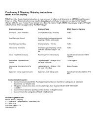
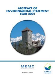
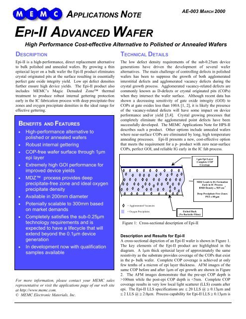
APPLICATIONS NOTEAE-003 MARCH 2000<strong>EPI</strong>-<strong>II</strong> <strong>ADVANCED</strong> <strong>WAFER</strong>High Performance Cost-effective Alternative to Polished or Annealed WafersDESCRIPTIONEpi-<strong>II</strong> is a high-performance, direct replacement alternativeto bulk polished and annealed wafers. By growing a thinepitaxial layer on a bulk wafer the Epi-<strong>II</strong> product eliminatescrystal originated pits at the surface resulting in essentiallyperfect gate oxide integrity yield. Low epi defect densitiesfurther ensure high device yields. The Epi-<strong>II</strong> product alsoincludes <strong>MEMC</strong>’s Magic Denuded Zone thermaltreatment to produce robust internal gettering protectionearly in the IC fabrication process with deep precipitate-freezones and oxygen precipitate densities in the ideal range foreffective gettering.BENEFITS AND FEATURES• High-performance alternative topolished or annealed wafers• Robust internal gettering• COP-free wafer surface through 1µmepi layer• Extremely high GOI performance forimproved device yields• MDZ process provides deepprecipitate-free zone and ideal oxygenprecipitate density• Available in 200mm diameter• Potenially scalable to 300mm basedon market demands• Completely satisfies the sub-0.25µmtechnology requirements and isexpected to have a lifecycle that willextend beyond the 0.1µm devicegeneration• In development now with qualificationsamples availableFor more information, please contact your <strong>MEMC</strong> salesrepresentative or visit the applications page of our web siteat http://www.memc.com.© <strong>MEMC</strong> <strong>Electronic</strong> <strong>Materials</strong>, <strong>Inc</strong>.TECHNICAL DETAILSThe low defect density requirements of the sub-0.25um devicegenerations have driven the development of several waferalternatives. The main challenge of controlling defects in polishedwafers has been to suppress the growth of both agglomeratedinterstitial defects and agglomerated vacancy defects during thecrystal growth process. Agglomerated vacancy-related defects arecommonly known as D-defects or crystal originated pits (COPs)when they intersect the wafer surface. Although recent data hasshown a decreasing sensitivity of gate oxide intregity (GOI) toCOPs at gate oxides less than 100A [1, 2], it is likely the presenceof the vacancy-related defects will have some impact on deviceperformance and/or yield [3,4]. Crystal growing processes thatcompletely eliminate the agglomerated point defects have beensuccessfully developed. The <strong>MEMC</strong> Applications Note for HPS-<strong>II</strong>describes such a product. Other options include annealed waferswhere near-surface COPs are eliminated by long, high temperatureannealing processes. Epi-<strong>II</strong> presents a new, cost-effective optionthat meets the requirement for a p- product with zero near-surfaceCOPs, perfect GOI, and reliable IG early in the IC fab process.= Agglomerated Vacancies= Oxygen Precipitates Etched Back(No Backside Films)Figure 1: Cross-sectional description of Epi-<strong>II</strong>1 mm Epi LayerComplete COPCoverageMDZ Leads to IG FormationEarly in IC ProcessBMD Density » 5E9 cm -3Deep Precipitate Free ZonesPFZ » 80 mmDescription and Results for Epi-<strong>II</strong>A cross-sectional depiction of an Epi-<strong>II</strong> wafer is shown in Figure 1.The key elements of the Epi-<strong>II</strong> product are highlighted in thediagram. A 1µm thick epitaxial layer of approximately the sameresistivity as the substrate provides coverage of the COPs that existin the p- bulk wafer. Complete COP coverage is achieved at onlyfew tenths of a micron of epi layer thickness. AFM images of thesame COP before and after 1µm of epi growth are shown in Figure2. The AFM images demonstrate that the pre-epi COP depth is>100nm while the post-epi COP depth is
Page 2<strong>EPI</strong>-<strong>II</strong> <strong>ADVANCED</strong> <strong>WAFER</strong>shown in Figure 3. GOI tests confirm that the 1µmepi layer eliminates the degradation associated withthe COPs on the p-bulk wafer. GOI results for 200Agate oxide tests are shown in Figure 4. IG protectionis achieved by applying the MDZ TM process followingepi deposition. Ideal oxygen precipitate densities andprecipitate-free zone depths are observed on Epi-<strong>II</strong>wafers after thermal cycling. Figure 5 shows acleaved and etched cross section of an Epi-<strong>II</strong> waferfollowing a two step thermal cycle (4 hours @ 800C +16 hours at 1000C). Additional results for the MDZ TMprocess can be viewed in the MDZ TMApplicationsNote.SummaryThe Epi-<strong>II</strong> product is a high-performance, cost-effectivealternative to polished and annealed wafers. Epi-<strong>II</strong>completely satisfies the sub-0.25µm technologyrequirements and is expected to have a lifecycle that willextend beyond the 0.1µm device generation. It deliversa COP-free surface with essentially perfect GOIperformance. The addition of the MDZ TMprocessensures robust gettering and deep oxygen precipitatefreezones. Competitive manufacturing costs areachieved by the combination of the thin 1µm epi layer,optimized epi process recipe, and lower substrate costincluding no backside films.COP Depth ≈ 130 nm before epiDepth ≈ 3nm after epiFigure 2: COP depths before and after 1um epi growth. Complete coverage of COPs leading to very low LLS counts.
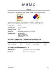
<strong>EPI</strong>-<strong>II</strong> <strong>ADVANCED</strong> <strong>WAFER</strong> Page 3References1 F. Gonzalez, M.R. Seacrist, M. J. Binns, A. Wang,S. Pirooz, and R. Barbour. In “Analytical andDiagnostic Methods for Semiconductor <strong>Materials</strong>,Devices, and Processes”. The ElectrochemicalSociety, Pennington, NJ. PV99-16, p. 496, 1999.2 T. Bearda, M. Houssa, P.W. Mertens, J.Vanhellemont, and M Heyns. Applied PhysicsLetters, 75, 1255, 1999.3 G.S. Lee, K.D. Kwack, J.G. Park, J.M. Park, andT.H. Shim. In “ULSI Process Integration”. TheElectrochemical Society, Pennington, NJ. PV99-16, p. 496, 1999.4 M. Muranaka, K. Makabe, M. Miura, H. Kato, S.Ide, H. Iwai, M. Kawamura, Y. Tadaki, M.Ishihara, and T. Kaeriyama, Japan JournalApplied Physics, 37, 1240, 1998.Epi-<strong>II</strong> LLS >= 0.13um, Tencor 6220 Inspection100%Cumulative % of Wafers90%80%70%60%50%40%30%20%10%0%0 5 10 15 20 25 30LLS Counts >=0.13umFigure 3: LLS distribution at >=0.13um. Low LLS Counts following Epi-<strong>II</strong>.Capacitor DefectDensity (Def/cm 2 )1086420Ramped Voltage Oxide Breakdown Test150, 0.1cm 2 Capacitors per Wafer, Tox = 200A0 1 2 3 4 5 6 7 8 9 10Field(MV/cm)P- Bulk Epi-<strong>II</strong>Figure 4: GOI defect density comparison between p- wafer and Epi-<strong>II</strong> wafer. COPs present in bulk wafer degrade GOI. Epi-<strong>II</strong> eliminates COP-related GOI degradation
Page 4<strong>EPI</strong>-<strong>II</strong> <strong>ADVANCED</strong> <strong>WAFER</strong>Epi layerDeepprecipitatefreezoneIdeal BMDdensityFigure 5: Epi-<strong>II</strong> cleaved and etched cross section following thermal cycle. Deep precipitate-free zone and ideal BMDdensity for effective gettering.<strong>EPI</strong>-<strong>II</strong>: IN SUMMARYPolished WaferStandard CZ (i.e., Open Hot Zone), Full-Ingot Resistivity, Etched BackAdd 1 µm of Epi for COP CoverageEpi Resistivity Targeted at Median of Substrate DistributionLow Epi Conversion Cost, Low Epi Defect Number DensityAdd MDZ Process for IG <strong>Inc</strong>orporationTailored Vacancy Profile Leads to Consistent Precipitation Early in IC ProcessLow Cycle Time ⇒ Low MDZ Conversion Cost