Nya Svetsaren 1, 1999. - Luleå University of Technology
Nya Svetsaren 1, 1999. - Luleå University of Technology
Nya Svetsaren 1, 1999. - Luleå University of Technology

Create successful ePaper yourself
Turn your PDF publications into a flip-book with our unique Google optimized e-Paper software.
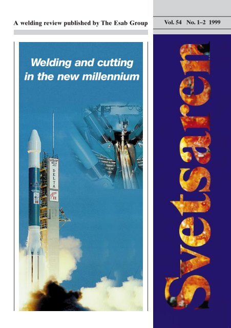
A welding review published by The Esab Group Vol.54 No.1–2 1999Welding and cuttingin the new millennium
A welding review published by The Esab Group No. 1–2 • 1999Articles in <strong>Svetsaren</strong> may be reproduced without permission but withan acknowledgement to Esab.PublisherBertil PekkariEditorLennart LundbergEditorial committeeKlas Weman, Lars-Göran Eriksson, Johnny Sundin, Johan Elvander, Dag Jacobsen,Jerry Uttrachi, Stan Ferree, Ben Altemühl, Nils-Erik Andersen, Susan FioreAddressEsab AB, Box 8004, S-402 77 Göteborg, SwedenInternet addresshttp://www.esab.seE-mail: info@esab.sePrinted in Sweden by Skandia-Tryckeriet, GöteborgThe Friction Stir Welding process isbeing used for the welding <strong>of</strong> fuel tanksin the Boeing Delta space rockets.Contents Vol. 54 No. 1–2 1999312Challenges for welding consumables for the newmillenniumImportant trends for materials developmentchallenges the development <strong>of</strong> consumables andprocesses.From prototype to integrated production system10 years <strong>of</strong> research and development results in theTHOR ArcWeld production system — a system forthe automatic programming <strong>of</strong> welding robots.4351Laser welding — A mature process technology withvarious application fieldsThe possible applications for laser welding in themanufacturing industries will be more or lessunlimited.Energy efficiency in weldingLower energy costs give better economy andenvironmental effects with the choice <strong>of</strong> the rightequipment.15Welding duplex chemical tankers the ESAB wayA review ot the production <strong>of</strong> chemical tankers atFactorías Vulcano S.A in Spain.53Effect <strong>of</strong> interpass temperature on properties <strong>of</strong>high-strength weld metalsThe microstructure <strong>of</strong> high-strength weld metalsbecomes sensitive to variations in the interpasstemperature in multirun welds.22Consumables for welding modified 9 Cr-1 Mo steelA comparison between modified and conventionalcreep-resistant ferritic steels and the consumablesto be used.59“The technology <strong>of</strong> tomorrow” has already beenimplemented at BORSIG in GermanyInstalling the new technologies for adaptive weldingand automatic robotic oxy-fuel cutting at BORSIG’sheavy-duty plant has clearly increased productivity.Increasing availabilityWith modern cutting systems it is possible to unifymachine investment and to cut workpiece idle timesdramatically.26Laser welding catalytic converters — a completesuccess for AP Torsmaskiner AB, SwedenLarge-scale production <strong>of</strong> laser-welded componentfor vehicles.6529Consumables for welding high strength steelsThe use <strong>of</strong> high strength steels increases the needfor new welding consumables70Fabricators pleased with increased submerged arcproductivity from cored wiresSAW with cored wires gives great benefits directlyfrom improved welding economy due to an increaseddeposition rate converted to higher travel speedWelding and cutting beyond the year 2000Major trends and conclusions from a gas-relatedpoint <strong>of</strong> view34Cutting systems in an environmental contextThe environmental issues have become an increasinglyimportant point on the agenda when it comesto the design <strong>of</strong> cutting systems743839New ESAB OK Tubrod 15.13 for robot welding atFincantieriThe future success <strong>of</strong> the European Union projectfor Fully Automatic Ship Production ultimately dependson the performance <strong>of</strong> cored wires when itcomes to optimising productivity.Stubends & Spatter77Modern MIG welding power sourcesFeatures <strong>of</strong> modern power source technology.2<strong>Svetsaren</strong> No.1–2 1999
Challenges for welding consumablesfor the new millenniumby Lars-Erik Svensson and Johan Elvander, Esab AB, Göteborg, SwedenFigure 1. The relative use <strong>of</strong> different welding processes, measured in the form <strong>of</strong> weld metal consumption.Arc welding was inventedaround 100 years agoand, at least during thepast 50 years, it hasbeen the main fabricationmethod for structuresmade <strong>of</strong> steel andother metallic materials.There are several arcwelding processes,which means that thereare many possible waysto optimise the weldingoperation. With many <strong>of</strong>the methods, the mechanisation<strong>of</strong> the processis possible and thiscan decrease the cost <strong>of</strong>welding. With the largenumber <strong>of</strong> consumablesavailable, the flexibilityrequired to achieve appropriateproperties inthe welded joint is veryhigh.The potential for adjusting thechemical composition <strong>of</strong> the weldmetal is almost unlimited. By usingdifferent flux systems, weldingcharacteristics such as drop transfer,arc stability and the fluidity<strong>of</strong> the molten metal can be controlled.However, to maintain pr<strong>of</strong>itability,industry must always lookfor ways <strong>of</strong> improving and rationalisingworking processes. Aswelding is such a central processfor many fabricators, the weldingoperation has been the focalpoint for many <strong>of</strong> the improvementswhich have been madeover the years. These improvementscan be categorised intothree main groups:developments in designdevelopment <strong>of</strong> welding processesdevelopments in materials.Of course, these developmentscannot be seen in isolation but<strong>Svetsaren</strong> No.1–2 1999 3
are interrelated. In order to discusspossible future developments,it may, however, be helpfulto make this division.Design developments fall outsidethe scope <strong>of</strong> this paper, but itcan be briefly stated that, withthe introduction <strong>of</strong> high-speedcomputers, finite element calculations<strong>of</strong> critical details in a structurehave become a standardtool, helping to optimise the constructionsignificantly. Althoughdesign is traditionally conservative,due to the major consequences<strong>of</strong> a failure, there is definitelya trend towards utilisingmaterials such as higher strengthsteels or aluminium to producelighter structures with a highload-carrying capacity. In thiscontext, it must be realised thatone <strong>of</strong> the controlling factors indesign is fatigue, which is a limitingfactor for the use <strong>of</strong> highstrengthsteels.With the development <strong>of</strong>mechanised welding, it is moreadvantageous to use fillet weldingrather than butt welding. To implementthis, the development <strong>of</strong>the welding processes took placeprimarily from 1930 and onwards.The most common processes likesubmerged arc welding, gas-tungstenarc welding and gas-metalarc welding were all developedmore than 50 years ago. Theyhave been further refined withthe aid <strong>of</strong> sophisticated electroniccomponents in power sources,elaborate handling devices likecolumns and booms and seamsensors. Many <strong>of</strong> the methods arenow fully automated. The productivity<strong>of</strong> the processes has alsobeen increased by a number <strong>of</strong>modifications. The best exampleis probably submerged arc welding,where productivity can be increasedby using multi-wire systemsor by feeding metal powderinto the weld pool. In gas-metalarc welding, the use <strong>of</strong> coredwires has led to an increase inproductivity. Here, too, modificationsto the process, as in RapidArc and Rapid Melt, have acquiredsome degree <strong>of</strong> popularity.In parallel with the developmentsin productivity, consumableshave also been developedto meet new and higher requirements.Three different situationshave been encountered;higher strength and impacttoughness as well as enhancedcorrosions resistance is desiredto match the development<strong>of</strong> steel,higher impact toughness atlower temperatures is neededfor structures operating inharsh environments to maintainstrength and toughnessfor welds deposited with higherproductivity (which generallymeans higher heat inputand coarser microstructures).Arc welding has been establishedfor many years as the leadingjoining process. In certain applications,other processes haveacquired increasing popularity. Inthe automotive industry in particular,many other joining processes,such as adhesives and laserwelding, have taken over fromtraditional arc welding. In mostother circumstances, arc weldingis still the leading process, despitethe fact that many other processeshave been developed. In recentyears, two other processes, laserwelding and friction stir welding,have been introduced and developedto such an extent that theycan be regarded as realistic challengersto arc welding. The benefitsto the user <strong>of</strong> these processesare that they are <strong>of</strong>ten performedin just one or two passes, even forrelatively thick material, and thatthe distortion <strong>of</strong> the plates is verysmall, resutling in far less workfor rectification. The drawbacksare the large investment costs andthe need for much closer fit-up <strong>of</strong>the plates. In the case <strong>of</strong> laserwelding, special grades <strong>of</strong> plateare needed and, in the case <strong>of</strong>friction stir welding, the supplementaryequipment for handlingthe plates is quite extensive. Inthe large research projects thathave been run or are still in progressand in which these processesare being evaluated, otherdrawbacks have also been noted.The ductility <strong>of</strong> laser welds is usuallylower than that found in arcwelds and, due to the very highcooling rates, martensite is <strong>of</strong>tenformed both in the heat affectedzone and in the weld metal. Frictionstir welding is still very muchmore at the development stageand has only been used commerciallyfor welding aluminium, withvery promising results. It is stillnot known whether it will be possibleto use this process for steelson a larger scale.Process developmentThe relative use <strong>of</strong> differentwelding consumable types, measuredin terms <strong>of</strong> weld metal consumption,for welding structuralsteel between 1975 and 1996 isshown in Figure 1. The figureshows the development for threeregions: Western Europe, theUSA and Japan.The use <strong>of</strong> covered electrodeshas been replaced by methodsproducing higher productivity.MIG/MAG welding, using solidwires, has captured the largestmarket shares. The consumption<strong>of</strong> tubular wire was less than 5%for many years, but, during thelast few years, it has increasedmarkedly and is now almost 10%.This consumption is expected tocontinue to increase rapidly.The decrease in the use <strong>of</strong> coveredelectrodes is expected to beless dramatic in the years tocome, although some further decreasecan still be foreseen. Thegrowth <strong>of</strong> tubular wires will thenbe due in part to a change in processfrom covered electrodes, butit will mainly result from the replacement<strong>of</strong> solid wires with tubularwires.The major change which is currentlytaking place is the increasinguse <strong>of</strong> welding robots andother forms <strong>of</strong> mechanisation.This trend is particularly strong incountries with high labour costs,but another, equally importantfactor is the difficulty involved infinding qualified welders who arewilling to perform manual welding.It has, in fact, been found thatthe wear and tear experienced bywelders, especially when weldingwith semi-automatic processes,can be quite high. To address thissituation, two possible methodscan be considered: either fullymechanise the operation or introduceanother method which imposesless weight on the welder’sarms and shoulders. The secondmethod has sometimes been4 <strong>Svetsaren</strong> No.1 1999
used. One example <strong>of</strong> this comesfrom Norway where, in a particularapplication, MMA weldingwith high-recovery covered electrodesreplaced semi-automaticwelding. It was actually foundthat productivity was not reducedbut was instead enhanced. Thelesson to be learned here is thatthere are several ways <strong>of</strong> achievinghigh productivity. High flexibilityand a careful analysis <strong>of</strong>the different options is most likelyto promote the optimum choice,which will in turn lead to maximisedproductivity.Environmental questions haveattracted increasing interest inmodern society. The demand formore environmentally-friendlyoperations has been stepped up— in the welding industry andother areas. Esab has played anactive part in improving the situationwith regard to the impacton the environment from manyparts <strong>of</strong> its operations. Detailsabout Esab’s environmental activitiescan be found in (1). Anew report describing further improvementswill be issued in<strong>1999.</strong>The main welding process inFigure 1 is MIG/MAG weldingwith solid wire. This is not surprising,due to the combination <strong>of</strong>flexibility, productivity and qualitythe method <strong>of</strong>fers. The latestdevelopments here are related tothe packaging system. For applicationswith high duty cycles, theintroduction <strong>of</strong> Marathon Pacwas a major improvement. MarathonPac has been further refinedand is now made <strong>of</strong> recyclablematerial. Using a special system,the wire always comes outstraight, producing extremely lowfriction in the wire conduit. Witha new and improved design, 12 mlong wire conduits are used.When starting, only the free wireneeds to be accelerated, therebyreducing the wear on the driverollers. The straight wire is a majorbenefit in different situationswhen the wire has to be positionedcarefully (e.g. welding innarrow gaps) or when welding inthin plate, for example. When usingrobot welding, joint trackingis critical and the straight wiremakes this much more accurate.The most important benefit <strong>of</strong>Marathon Pac is, however, the opportunityto increase productivity.The number <strong>of</strong> bobbin changes isreduced significantly, repairs andrejects are reduced and it is possibleto run unmanned shifts duringthe night.Further improvements on thepackaging side are expected. Atpresent, Marathon Pac is availablein two sizes. The serial connection<strong>of</strong> several MarathonPacs, to reduce the number <strong>of</strong>changes, has also been testedwith promising results.The most important factor fora fabricator using robotic weldingis that the robot can run continuously.This in turn leads to requirementsbeing imposed on theequipment and consumables, togetherwith high and consistentquality to create the conditionsnecessary for problem-free operation.For the wires at a robot weldingstation, feedability and ease<strong>of</strong> arc striking are essential properties.The new robotic wire,PZ6105R, from Filarc is one example<strong>of</strong> this development.Most robots are designed forsolid wires, but they can be changedrelatively simply to coredwires and the different parametersettings that are needed. The advantages<strong>of</strong> metal cored wirescompared with solid wires arethe higher welding speeds thatcan be attained, the improvementin penetration and the reductionin spatter.As soon as a robot is installed,the handling time is more or lessconstant, independent <strong>of</strong> thechoice <strong>of</strong> process. So, the onlyway to increase productivity stillfurther is to increase the weldingspeed (e.g. use <strong>of</strong> cored wires).The higher and broader penetrationin fillet welds produces a<strong>Svetsaren</strong> No.1 1999 5
larger safety margin for the constructionand the opportunity forwider tolerances in the fit-up.There are also discussions aboutwhether it is possible to take account<strong>of</strong> the penetration whencalculating the throat thickness.This would add a further benefitto the cored-wire process andwould also be a significant costreductionfactor. Another importantfactor is the bead shape,which is much smoother for thecored-wire process. The transitionbetween the weld metal and thebase material is also muchsmoother with cored wires, somethingthat is very important forconstructions subjected to fluctuatingloads. The low spatter reducesthe need for post-cleaningto a minimum, thereby enablingwelded parts to be immediatelytransported to the next link inthe manufacturing chain.There are some further developmentin the MAG process(twin-arc MAG and tandemMAG) which may be <strong>of</strong> significantinterest for the future. Intwin-arc MAG, two wires are fedinto the same torch and connectedto a sophisticated power source.The wires have the same voltage,but different feeding rates.By pulsing, disturbances betweenthe arcs are avoided. This processproduces extremely high depositionrates. The process has alsobeen tested with metal coredwires (PZ 6105R and OK Tubrod14.13) with good results.Submerged arc welding hashad a fairly stable share <strong>of</strong> themarket over the years. It is ahigh-productivity process and theapplications are therefore <strong>of</strong>tenassociated with heavy industry. Anumber <strong>of</strong> improvements havebeen made for even higher productivity,such as increasing thenumber <strong>of</strong> welding wires. Onerelatively new development involvesusing a tubular wire instead<strong>of</strong> a solid wire. This increasesthe deposition rate, improvesthe penetration pr<strong>of</strong>ile andmakes the adaptation <strong>of</strong> chemicalcomposition much easier. Theprocess is now being further optimised,with the joint development<strong>of</strong> the cored wire and theflux, to provide a better process.One further example <strong>of</strong> developmentwithin this field is the use<strong>of</strong> a cold wire, which is fed separatelybut in synchronised form,into the weld pool. This featureboth increases productivity significantlyand helps to cool theweld, thereby preventing excessivegrain growth. A patent forthis process has now been filedby Esab.In the future, it is expectedthat, in the case <strong>of</strong> assemblywelding, especially for heavyequipment, covered electrodeswill still be used. The use <strong>of</strong> tubularwires will increase significantly,especially in Europe. Tubularwires will replace covered electrodes,as well as solid wires tosome extent. The main developmentswill be seen in tubular andsolid wires, particularly in connectionwith mechanised welding.For the technically most advancedfabricators, sophisticatedmethods like laser welding willbe introduced. For fabricatorswho cannot invest the very largeamount <strong>of</strong> money required for lasers,advanced methods like twinarcMIG, which is still based onrelatively conventional powersources, but with advanced s<strong>of</strong>tware,could be one possible way<strong>of</strong> increasing productivity. However,the majority <strong>of</strong> fabricatorsare small and medium-sized enterprisesand, as a result, conventionalwelding methods will stillbe used. Productivity will then beobtained from using more efficientconsumables.Developments in structuralsteelThe large advance in terms <strong>of</strong> theweldability <strong>of</strong> structural steelscame with the introduction <strong>of</strong> thethermo-mechanically (TM) processedsteels at the beginning <strong>of</strong>the 1980s. Compared with the traditionalnormalised steels, thenew steels had a much leanercomposition, for the same yieldstrength. The carbon content inparticular was reduced and thestrength was obtained from finergrain size and increased dislocationdensity. Sometimes, acceleratedcooling was used, adding extrastrength as the steel transformedto bainite rather than ferrite.In addition to the lower carboncontent, the quality <strong>of</strong> the steelswas improved significantly by areduction in the impurity element(sulphur and phosphorus) content.It is difficult to envisage a similarmajor development in steels inthe near future. Slow and continuousimprovements will probablybe made to TM steels — in terms<strong>of</strong> their impact properties, for example— and they may find newapplications, but, as there willprobably be no major changes,there will be no need to makeany significant changes to theconsumables used for weldingthese steels.In the new European standardEN 10 113-3, TM steels with yieldstrengths <strong>of</strong> up to 460 MPa arespecified. TM steels can now beproduced at many steelworks.What might differ between suppliersis the combination <strong>of</strong> platethickness and yield strength thatcan be delivered. Many <strong>of</strong> thesteels supplied with yieldstrengths <strong>of</strong> up to approximately500 MPa are made using the TMprocess. For the highest strengthlevels in this range, the productionprocess is determined by theplate thickness. For thinner plates,the TM process can be used,but for heavier plates it is necessaryto use quenching and temperingto obtain the properties.Above approximately 500 MPa,all steels are <strong>of</strong> the QT type.These steels are also <strong>of</strong> high quality,with a low impurity contentand good weldability. However,with increasing strength levelsand increased thickness, more alloyingis needed, making preheatingnecessary.A trend that has continued forsome years involves using steels<strong>of</strong> higher strength. The advantage<strong>of</strong> this is obvious; structures canbe made with thinner plates, reducingthe weight and therebyimproving the opportunity forhigher loads. It should be notedthat there are situations in whicha structure cannot take advantage<strong>of</strong> thinner plates, such as whenbuckling, stiffness or fatiguestrength is the design criterion.High-strength steels are commonlydefined as steels with a6 <strong>Svetsaren</strong> No.1 1999
Consumable type Hydrogen content Comments(ml/100 g weld metal)Basic covered electrodes 5 3 ml for special typesTubular wires,basic or metal cored < 5Tubular wires, rutile < 10 <strong>of</strong>ten < 5Submerged arc fluxes < 5Table 1. Hydrogen content <strong>of</strong> different consumables.yield strength <strong>of</strong> more than 350MPa.These steels now have foundtheir way into many areas <strong>of</strong> construction.In several new spectacularbridge constructions, TMsteels with yield strengths <strong>of</strong> 420or 460 MPa have been used. Oneexample is the Great Belt bridgein Denmark which was built duringthe mid-1990s and recentlywent into operation. Part <strong>of</strong> thebridge is made in the form <strong>of</strong> asteel suspension bridge, usingsome 80,000 tonnes <strong>of</strong> steel. Halfthis amount is accounted for byTM steels, with a yield strength <strong>of</strong>420 MPa. Details <strong>of</strong> the building<strong>of</strong> this bridge are presented in(2).Another example from thebridge sector, in which a veryhigh-strength QT steel is used, isthe world’s largest suspensionbridge, the 1,990 m long Akashibridge in Japan. The construction<strong>of</strong> this bridge was completed in1997 and the bridge is now in operation.In the box girders <strong>of</strong> thisbridge (comprising hundreds <strong>of</strong>tonnes <strong>of</strong> the steel), a very highstrengthsteel, HT780, with a yieldstrength <strong>of</strong> more than 780 MPawas used. It is particularly interestingto note that this steel onlyneeded less than 50°C <strong>of</strong> preheating,despite its high strength, dueto the elaborate alloying technique,combined with the quenchingand tempering technique (3).Examples <strong>of</strong> applications forhigh-strength steels with yieldstrengths <strong>of</strong> up to around 500MPa include standard structuralsteelworks, excavator equipment,pipelines, cranes, ro<strong>of</strong> support inmines and, <strong>of</strong> course, <strong>of</strong>fshoreconstructions.Steels <strong>of</strong> higher strength suchas 690 MPa are used for trailersfor heavy haulage work, craneswith a high lifting capacity, dumperbodies and so on. For steelswith even higher strength (900MPa and above), typical applicationsinclude penstocks, conveyorsystems and mobile bridges.For steels with a yield strength<strong>of</strong> 350-450 MPa, there are usuallyvery few welding problems. Theproblems that can arise here includelow toughness in the weldmetals, <strong>of</strong>ten associated with increasednitrogen content, due tothe use <strong>of</strong> too long an arc. If lowhydrogenconsumables are used,hydrogen cracking is very rarely aproblem. If it arises, it is relatedto the welding <strong>of</strong> heavy plates.Solidification cracking may occurin very special circumstances, butit should generally pose no problems.Impact toughness in highdilutionwelds, such as one-sidedwelding with only one bead, cansometimes be low. This is, however,<strong>of</strong>ten due to some incompatibilitybetween the base metaland the consumable.It is not until steels with a yieldstrength <strong>of</strong> 600 MPa or above areused that welding may becomesomewhat problematic and requiremore caution. The steels areused in demanding applications,requiring good toughness at lowtemperatures in many cases. Inthis case, two problems may occur.The first involves finding aweld metal with a yield strengthhigher than that <strong>of</strong> the steel andat the same time possessing goodimpact toughness. There are anincreasing number <strong>of</strong> consumableswith these properties, butthere may still be problems whenit comes to combining high productivityand good mechanicalproperties. This is discussed inmore detail in the paper by L-ESvensson in this issue.The second problem is relatedto hydrogen cracking. With thesteel developments that have takenplace, including a lean alloyingcontent, the weldability <strong>of</strong> thesteels has been increased. In particular,the need for preheatinghas been reduced dramatically.This is especially true <strong>of</strong> steels <strong>of</strong>lower strength, such as 350–500MPa steels. For these steels, theweld metals are also lean in alloyingcontent and do not requirepreheating. However, when itcomes to the high-strength steels,the situation is more complicated.The only way to increase thestrength <strong>of</strong> these weld metals is toincrease alloying. The advancedprocessing routes used for thesteels can naturally not be appliedto the weld metal. So, in asituation in which there is lesshardenability in the HAZ than inthe weld metal, there may be severalreasons why hydrogen crackingwould be more likely to occurin the weld metal. Preheatingmust then be prescribed to protectthe weld metal rather thanthe HAZ <strong>of</strong> the parent plate. Thisis a somewhat new situation and,although fabricators have learnthow to handle it, there is a lack <strong>of</strong>fundamental knowledge aboutweld metal hydrogen crackingwhich must be remedied.One solution that might appearto an attractive means <strong>of</strong> resolvingthis situation is a further reductionin hydrogen content fromthe consumables. Developmentsin which the hydrogen content <strong>of</strong>the weld metals has been reducedhave already been in progress formany years. As was noted in aprevious paper (4), hydrogen contentsas specified in Table 1 havebeen obtained as a result <strong>of</strong> intensiveresearch and developmentduring the past decade.There are several reasons forbelieving that the rate at whichthis downward trend will continuewill be slower in the futurethan it has been in the past. It willbe increasingly difficult to makefurther reductions from the verylow levels that have already beenachieved. The hydrogen contentcan be reduced by a number <strong>of</strong>measures. Unfortunately, thesechanges <strong>of</strong>ten tend to have a negativeeffect on other properties,<strong>Svetsaren</strong> No.1 1999 7
Alloy Minimum preheating Max interpass Post-weldtemperature °(C) temperature °(C) heat treatment (°C)0.5 Mo 75 250 600-650(t > 15 mm) (t > 30 mm)1Cr-0.5 Mo 100 300 650-750(t > 15 mm) (all thickness)2.25Cr-1Mo 200 350 700-750(t > 15 mm) (all thickness)9Cr-1 Mo 200 350 700-770(all thickness)(all thickness)12Cr-1Mo 350 450 intercooling to 125-150(all thickness) PWHT 700-770Table 2 Preheating, interpass and post-weld heat treatment temperatures for Cr-Mosteels. Based on draft for standard “Welding <strong>of</strong> ferritic steels”.such as welding characteristics.So, a further reduction in hydrogenwill lead to consumableswhich are less attractive to thewelder. This factor has to be takenseriously and evaluatedagainst the benefits <strong>of</strong> a furtherreduction in the hydrogen content.Another important factor ishow accurately the measurement<strong>of</strong> hydrogen content can be made.Investigations have shown thatthe error is around 0.5–1.0 ml/100g weld metal for the gas chromatographymethod. The relative errorat, say, 2 ml hydrogen/100 gweld metal is then 25-50%. Itmust be noted here that the largeerrors are not due to the analyticalequipment but instead to variationsin the specimen preparationphase.Apart from hydrogen stemmingfrom the consumable, there areother sources <strong>of</strong> hydrogen, such asthe surrounding atmosphere, thebase material or dirt and oil onthe plate and joint surfaces.So, the amount <strong>of</strong> hydrogen inthe weld pool can differ from thehydrogen content specified by theelectrode manufacturer. Naturally,the hydrogen content <strong>of</strong> theconsumable is also affected bythe possible moisture absorption.Although low moisture absorptionelectrodes have been developed,some absorption alwaystakes place. This can be avoidedby using vapour-tight packaging,like Esab’s VacPac. In this kind <strong>of</strong>packaging, the electrodes arekept in the same condition aswhen they were manufactureduntil the package is opened.To benefit fully from the development<strong>of</strong> steels, to increase productivityduring welding, systematicinvestigations need to bemade, partly to be able better todefine the preheating necessaryfor safe welding, but also in orderpossibly to develop the weld metalsstill further with the aim <strong>of</strong>making them crack-resistant whilemaintaining the mechanicalproperties.Developments in heatresistantsteelsThe steels which are traditionallyused for high-temperature applicationswithin the petrochemicalindustry or the power generatingindustry can broadly be classifiedinto two groups. One group, specifiedin EN 10 028-2 Steels forpressure purposes, with specifiedelevated temperature properties,contains those steels commonlyfound in high-temperature powerplants. In this standard, there arefirst four unalloyed quality steels,with a yield strength varying from235 to 355 MPa. The properties <strong>of</strong>these steels are specified up to400°C. For use at higher temperatures,steels alloyed with molybdenumand chromium are used.The simplest steel is only alloyedwith about 0.3% molybdenum.The most common steels are alloyedwith either 1.25Cr-0.5Mo or2.25Cr-1Mo. These steels havetheir tensile properties specifiedup to 500°C. The maximum operatingtemperature is 565°C. Thecreep properties, given as referencein the standard, are specifiedup to 600°C for a 2.25Cr-1Mosteel (10 CrMo 9-10).There are a number <strong>of</strong> suggestionson how to modify the2.25Cr-1Mo steel in particular.The most frequent suggestionsare to increase the chromiumcontent, so that the typical compositionwould be 3Cr-1Mo instead,and to add vanadium. Theaddition <strong>of</strong> vanadium increasesthe high-temperature strength effiectively,but the cracking risk inthe HAZ is increased.Consumables for welding thesesteels have much the same compositionas the parent material.The microalloying elements vanadiumand niobium are on a lowerlevel than they are in the steel,thereby reducing the creepstrength <strong>of</strong> the weld metals somewhat.Since the microstructure <strong>of</strong>the weld metal is bainitic, theprior austenite grain boundariesare preserved and may be a source<strong>of</strong> embrittlement. In general,the welded joint is annealed afterwelding, to improve toughnessand reduce residual stresses. Incommon with other similar microstructures,the weld metals cansuffer from two types <strong>of</strong> embrittlement.During annealing, whichtypically takes place at 690°C,carbides can precipitate on theprior austenite grain boundariesand this can lead to lower toughness.This is called irreversibleembrittlement, as it is difficult toremove the carbides. At lowertemperatures, typically 400-500°C,reversible embrittlement may occur.This is due to the segregation<strong>of</strong> impurity elements, like phosphorus,to the prior austenitegrain boundaries. This processmay take place either during slowcooling through the critical temperatureregime or if the constructionis operating at this temperature,as is common in theprocess industry, for example.To prevent reversible embrittlement,it is important that thephosphorus content is reduced tothe absolute minimum. The degree<strong>of</strong> segregation and embrittlementis also influenced by otherelements and formulae have beendeveloped to help control thepermissible content <strong>of</strong> variouselements. The best-known <strong>of</strong> theseformulae is the Bruscato X-factor (5).For more demanding applications,steels with higher alloyingcontents are used. The steel with8 <strong>Svetsaren</strong> No.1 1999
Steel type Chemical composition (%) Tensile PREproperties(N/mm 2 )C Cr Ni Mo N Others R p0.2 R m *)AusteniticsASTM 304L 0.02 18.5 9.5 - - 205 520 19ASTM 316L 0.02 17.0 11.5 2.7 - 205 500 27UNS NO8904 0.01 20.0 25.0 4.5 - Cu 220 500 36Super-austeniticsUNS S31254 0.01 20.0 18.0 6.2 0.20 Cu 300 650 43UNS S32654 0.01 24.2 17.9 7.2 0.45 Cu 430 750 55DuplexUNS S31803/S32205 0.02 22 5.5 3.0 0.18 480 680 35SuperduplexUNS S32750 0.02 25 7.0 4.0 0.28 540 780 42*) PRE = %Cr + 3.3%Mo + 16%NTable 3. Examples <strong>of</strong> stainless steels, with typical compositions and properties.Consumables Weld metal chemical Tensile FN PRE Impactcomposition (%) properties toughness(N/mm 2 )–60°C (J)C Cr Ni Mo N R p0.2 R mOK 67.55 0.03 22.0 9.0 3 0.17 645 800 30-45 35 65OK 68.55 0.03 25.5 9.5 4 0.25 700 900 30-50 43 45Table 4 Duplex weld metals for MMA. The composition <strong>of</strong> the weld metals isrepresentative <strong>of</strong> other welding processes as well.the highest alloying content inthis group is 12Cr-1Mo steel.However, most interest in recentyears has focused on steels withabout 9% chromium-1% molybdenum,where large-scale developmentshave taken place.About 20 years ago, work beganin the US on the development<strong>of</strong> a steel <strong>of</strong> the 9Cr-1Motype, with high-temperature characteristicslike those <strong>of</strong> a 12Cr-1Mo steel but far better weldability.Another aim was to be able toincrease the operating temperature<strong>of</strong> power plants to around600°C, thereby significantly increasingefficiency. The modificationfrom the original 9Cr-1Mosteel lies primarily in the addition<strong>of</strong> vanadium, niobium and nitrogen.This modified steel has alreadyfound a number <strong>of</strong> applications,mainly in the form <strong>of</strong> pipes.Developments in this field arerapid. There are suggestions fornew steel compositions, like 9Cr-2Mo, or to replace molybdenumwith tungsten. The aim here isfurther to improve the creepproperties. These developmentswill call for the further development<strong>of</strong> weld metals. It is expectedthat, if the 9Cr type <strong>of</strong> steelcontinues to increase, by beingused in the petrochemical industry,for example, this will be one<strong>of</strong> the most intensive and interestingarea <strong>of</strong> materials developmentin the years to come.The weldability <strong>of</strong> Cr-Mo steelsis limited and weldability deterioratesas the alloying content increases.Preheating and post-weldheat treatment are required tovarying degrees for many <strong>of</strong> thesteels. A summary <strong>of</strong> the recommendationsfor welding thesesteels is given in Table 2. For allsteels, consumables with matchingproperties (and <strong>of</strong>ten very similarchemistry) exist, for all the commonprocesses. Note that 12Cr-1Mo is an exception. This alloy isnot welded using high-productivitymethods. However, consumablesfor welding 9Cr-1Mo modifiedsteels are still being developed.Some <strong>of</strong> the characteristics<strong>of</strong> these weld metals are detailedin the paper by E-L Bergqvist inthis issue.Developments in stainlesssteelThe use <strong>of</strong> stainless steels hasbeen increasing worldwide for along time and this trend is expectedto continue. Apart from thecommon grades, significant developmentshave taken place when itcomes to new grades with improvedcharacteristics (see Table3). Ferritic-austenitic duplex andsuperduplex, as well as superausteniticsteel, have been developed.One <strong>of</strong> the important drivingforces behind the development<strong>of</strong> new stainless steel hasbeen the need to improve characteristicsin chloride-containingenvironments. This harsh environmentgives rise to both pittingand stress corrosion cracking.These types are now beingused in increasing tonnages in theoil and gas industry, in the pulpand paper industry, in other types<strong>of</strong> process industry and in applicationssuch as chemical tankers,for example.Information about some austenitic,duplex, superduplex andsuperaustenitic steels is given inTable 3.The welding <strong>of</strong> stainless steel iswell established and a range <strong>of</strong>consumables suitable for all thecommon welding processes isavailable.There is a fairly extensive range<strong>of</strong> consumables for welding duplexsteels using all the differentwelding processes. Representativeexamples are given in Table 4. Atthe present time, it appears thatthe development <strong>of</strong> the family <strong>of</strong>duplex steels has slowed downand that modifications are beingmade to existing types rather thandeveloping new steels. The use <strong>of</strong>duplex and super-duplex steelscan be expected to increase steadilyin the years to come.Duplex materials are especiallysuitable in environments wherethere is a risk <strong>of</strong> stress corrosioncracking — in other words, environmentswhich frequently containchloride. Even the highestalloyedduplex steels are, howev-<strong>Svetsaren</strong> No.1 1999 9
er, susceptible to crevice corrosionin certain conditions (highertemperatures, de-aerated water,very high chloride content). Towithstand seawater environments,like the North Sea, with a chloridecontent <strong>of</strong> around 21,000ppm, the steels need to be improvedstill further.Alongside the development <strong>of</strong>the duplex and super-duplex, afamily <strong>of</strong> steels, known as superausteniticsteels, was developed.Some examples <strong>of</strong> these steels aregiven in Table 3. In typical cases,they contain around 20% chromium,18% nickel, 6% molybdenumand 0.2% nitrogen. Chromiumand molybdenum produce excellentcorrosion characteristics, whilenitrogen stabilises the austeniteand reduces the risk <strong>of</strong> sigmaphase formation during welding.The advantage <strong>of</strong> these steels isthat they have better ductility andimpact strength than the duplexand super-duplex steels. The yieldstress <strong>of</strong> super-austenitic steels is,however, lower than that <strong>of</strong> duplexsteels (<strong>of</strong> the order <strong>of</strong> 350MPa). The corrosion resistance <strong>of</strong>these super-austenitic steels ismore or less the same as that <strong>of</strong>the super-duplex steels, as isshown by the similar PRE values(Table 3).In order to comply with extremelyrigorous corrosion requirements,the super-austeniticsteels have been improved stillfurther. Examples <strong>of</strong> steels withhigher PRE values include Alloy31 from VDM and 654 SMO fromAvestaSheffield. These materialsare generally included amongstainless steels, but they aresometimes on the borderline <strong>of</strong>nickel-based alloys.Super-austenitic steels are notwelded with consumables <strong>of</strong> thesame type, as it is not possible toobtain sufficiently high PRE valueswith these weld metals. Theprincipal problems are caused bythe molybdenum content. Molybdenumsegregates heavily duringsolidification and the areas whichare poor in molybdenum have afar lower PRE value than theparent metal. Nor is it possible tocompensate for the molybdenumwith other alloying elements, asthis leads to a significant risk <strong>of</strong>intermetallic phase precipitation.Consumables <strong>of</strong> the nickel-basetype are used to weld these steels.The most common type is Ni-21Cr 9 Mo 3 Nb, which is used formost welding processes. Potentialproblems with this compositionare hot cracking and the precipitation<strong>of</strong> intermetallic phases. Toavoid this, a low heat input andlow interpass temperature shouldbe used and dilution should berestricted. A better choice may beto use the recently developed alloyNi-23 Cr 16 Mo instead (6).Very recently, the development<strong>of</strong> stainless steels for <strong>of</strong>fshore activitieshas taken a different route.For cost-saving reasons, anddue to increasing experience <strong>of</strong>the corrosion potential <strong>of</strong> the mediathat are transported, there isan initiative to develop so-calledsuper-martensitic steels and weldmetals. These steels, which have arange <strong>of</strong> composition <strong>of</strong> around10-13 % Cr, 2-4% Ni and 0-6%Mo, all with an extremely lowcarbon content, are now the subject<strong>of</strong> intensive research and developmentprogrammes. More informationon these steels is presentedin the paper by L Karlssonin this issue.Another trend that has emergedrelatively recently is the attemptto improve the weldability<strong>of</strong> steels at the lower end <strong>of</strong> thestainless steel range, namely steelwith a chrome content <strong>of</strong> around10-12 %. These steels are interestingfor use in the transport sector.The most popular method forwelding stainless steel is manualmetal arc, followed by MIG usingsolid wires. However, with solidwires, there is a greater risk <strong>of</strong>weld defects, such as lack <strong>of</strong> fusion.Cored wires, which have recentlybeen developed for many<strong>of</strong> the common stainless steel grades,improve this situation significantly.Productivity is enhancedby about 30% and spatter is significantlyreduced. Cored wireshave been developed for bothdownhand and out <strong>of</strong> positionwelding.Developments inaluminiumAluminium is finding more widespreaduse in most engineeringstructure segments. The new highspeedferries for Stena Line betweenSweden and Denmark andacross the Irish Sea are good examples<strong>of</strong> the way aluminium isbeing utilised to obtain a lighterweight to permit either a higherload-carrying capacity or fasterspeeds. However, the use <strong>of</strong> aluminiumhas also made it necessaryto redesign the ferry construction.The advantages <strong>of</strong> aluminiumas an engineering metal are obvious;it is a light and yet comparativelystrong material, with relativelygood corrosion. It is alsoenvironmentally-friendly, in thatit is recyclable. There are alsosome drawbacks to aluminium;the lower Young’s modulusmakes it less stiff, the high thermalexpansion coefficient induceshandling problems during weldingand straightening operationsand large amounts <strong>of</strong> energy arerequired for the production <strong>of</strong>raw aluminium.The drawbacks to aluminiummentioned above, combined withother things, like the loss <strong>of</strong>strength in the heat affected zoneduring welding, are making designand fabrication in aluminiumdifferent from that in steel.The difference compared withsteel can be clearly seen whenwelding aluminium. At present,the principal technical problemsassociated with the welding <strong>of</strong> aluminiumaresolidification cracks in theweld metalliquation cracks in the heat affectedzonepore formation andstrength reduction in the heataffected zoneBoth solidification and liquationcracks are thought to be duein the main to the occurrence <strong>of</strong>intermetallic phases with a lowmeltingtemperature at the grainboundaries. Alloys with a widesolidification range are the mostsusceptible to cracking. Thismeans that it is the hardenablealloys, to which zinc or copperhave been added, which are mostsusceptible to cracking. Some alloysalso contain lead, therebyincreasing the risk <strong>of</strong> cracking.Solidification cracks can beavoided by selecting silicon-10 <strong>Svetsaren</strong> No.1 1999
alloyed consumables. It has alsobeen demonstrated that siliconalloyedconsumables reduce therisk <strong>of</strong> liquation cracks in hardenableAl-Mg-Si alloys, probablybecause the solidification temperature<strong>of</strong> the weld metal islower than that <strong>of</strong> the parentmetal and any cracks thereforehave time to heal before stress iscreated across the joint. In thesolid-solution strengthening alloys,mainly alloyed with magnesium,it is those with a low magnesiumcontent that are the mostsusceptible to cracking. However,many alloys, in particular thenon-hardnable ones, but also thehardenable magnesium-siliconalloys, have very good weldability.Pores in aluminium welds areusually caused by hydrogen frommoisture. There is a very greatdifference in the solubility <strong>of</strong> hydrogenbetween the molten andthe solid state. So, when solidification<strong>of</strong> the weld metal occurs,there is large supersaturation <strong>of</strong>hydrogen. The hydrogen is thenprecipitated as pores. To keep thepore formation to a minimum,the hydrogen content must beminimised. All sources <strong>of</strong> hydrogen(i.e. the shielding gas, parentmetal and consumables) must beclosely controlled. Recent investigations(7) have shown that thematerial in the gas hoses has amajor influence on the moisturecontent. Hoses made from PVCor rubber give <strong>of</strong>f moisture in largequantities and must be flushedwith gas for perhaps 10 minutesafter they have been idle forsome time. Hoses made from PEor PTFE have a much lowermoisture pick-up and the time forflushing can consequently be reduced.Higher heat input is anotherway to improve the situation, as itgives the hydrogen longer tomove out <strong>of</strong> the weld pool. However,despite these actions, it isdifficult completely to suppresspore formation.The reduction in strengtharound a weld in aluminium alloysis inevitable, except for alloysin the untreated or room-temperature-agedcondition. This loss <strong>of</strong>strength is due to recovery andrecrystallisation in deformationhardenedalloys and precipitationcoarsening and dissolution in agehardenedalloys. To compensatefor the strength reduction, severalstrategies are used. Most frequently,welds are placed in lowstress areas. Other methods includelocally increasing the thickness<strong>of</strong> material. Heat-treatablealloys can, in principle, be givenrenewed heat treatment (solutiontreatment and ageing) to restorethese properties, but this approachnaturally involves manypractical difficulties.Aluminium is almost exclusivelywelded using MIG or TIG.There is a wide range <strong>of</strong> consumablesfor welding aluminium, eitherpure aluminium or solidsolution-hardened alloys. Thewelding wires are mainly alloyedwith magnesium or, in the case <strong>of</strong>certain alloys, silicon. Modificationsto the Al-Mg-system aremade by adding manganese invarying amounts, to increase thestrength still further.The addition <strong>of</strong> titanium or zirconium,to act as grain refiners, isalso quite common. However, thedevelopment <strong>of</strong> new alloys forwelding wires is relatively slow,probably reflecting the demandfrom the market.ConclusionsThe most important trends whenit comes to materials developmentand which will challenge thedevelopment <strong>of</strong> consumables are:improved productivity forcommonly used steelsincreased use <strong>of</strong> steel with improvedpropertiesFor consumables, future developmentswill focus ontubular wires, for both structuraland stainless steelsnew consumables with improvedhigh-temperaturecharacteristicsnew consumables with improvedcorrosion propertiesthe development <strong>of</strong> consumableswith an even lower hydrogencontent, but also animproved understanding <strong>of</strong>weld metal hydrogen crackingmechanismsOn the process side, the followingtrends are anticipated:high-productivity systemsbetter s<strong>of</strong>tware for processcontrolmore consumables suitable formechanisationReferences1 Esab Environmental Report 19972 F. Rouvillian, High strength steel in amajor bridge construction over theGreat Belt <strong>Svetsaren</strong>, V 49, 1, p 15, 19953 H. Mabuchi, Recent progress in structuralsteels for building and bridges, ISIJ,no 159, Feb 19964 A Backman, Development within materialstechnology - Consumables in the21st century, <strong>Svetsaren</strong>, V 49, 1, p 4,19955 R Bruscato, Temper Embrittlement andCreep Embrittlement <strong>of</strong> 2 ºCr-1 MoShielded Metal-Arc Weld Deposits,Welding Journal, 49, p 148-s, 19706 L Karlsson, S L Andersson, S Rigdaland T Huhtala, New Ni-base consumablesfor welding <strong>of</strong> highly alloyedstainless steels, Proc Stainless steels ’96,Dusseldorf/Neuss, June 3-5, 19967 Aga AB, O Runnerstam, private communicationAbout the authorLars-Erik Svensson, PhD, is manager<strong>of</strong> the Esab Central Laboratoriesin Gothenburg. He has workedfor more than 15 years withwelding metallurgy, focusing primarilyon unalloyed and low-alloyedsteels. He has published onebook and more than 25 papers onthe microstructure and properties<strong>of</strong> welds.Johan Elvander, M. Sc, (Materialseng.) joined Esab AB in 1982 aftergraduating from The Royal Institute<strong>of</strong> <strong>Technology</strong> in Stockholm.He started as development engineerfor stick electrodes and nowholds a position as head <strong>of</strong> Research& Development, businessarea Consumables in Europe.<strong>Svetsaren</strong> No.1 1999 11
From prototype to integratedproduction systemThe robot workscontinuallyThe joint venture between thetwo companies in the TOMATOproject has resulted in the identification<strong>of</strong> a series <strong>of</strong> technicalsuccess criteria for the introduction<strong>of</strong> THOR ArcWeld at a manufacturingcompany.The immediate advantage <strong>of</strong><strong>of</strong>f-line programming is that therobot can keep working, whilethe programming is handled on<strong>of</strong>fice computers.With CAD data as the startingpoint, it is possible to generate ageometrical model <strong>of</strong> a work celland workpiece. Subsequently, acollision-free trajectory is calculatedfor the welding robot in inbyCharlotte Hybschmann Jacobsen and Michael Wehner Rasmussen,AMROSE A/S, DenmarkRobot arc welding <strong>of</strong> industrial mixer at Ib Andresen Industri.Close to 10 years <strong>of</strong> researchand developmentare culminating in thefirst industrial productin the shape <strong>of</strong> theTHOR ArcWeld productionsystem, a systemfor the automatic programming<strong>of</strong> weldingrobots, integrating theentire process from theimport <strong>of</strong> CAD data tothe execution <strong>of</strong> robotprograms.During the past year, the R&Dcompany AMROSE A/S inOdense in Denmark has beencollaborating with Ib AndresenIndustri A/S in Langeskov inDenmark in the EU projectknown as TOMATO. The aim <strong>of</strong>the project has been to transferthe advanced robot technology(developed by AMROSE in closecollaboration with Odense SteelShipyard Ltd.) to other metal industries.The first working prototype <strong>of</strong>a robotic production system controlledby AMROSE technologywas successfully built and installedat Odense Steel ShipyardLtd. in 1994–95 and it is still beingused in the daily production <strong>of</strong>ship assemblies.The TOMATO project has focusedon developing the userinterface and adapting the technicalfunctionalities in order to ensurethat the system meets thedemands imposed by companiesin the metal industry for a flexibleproduction system.An internal demonstration <strong>of</strong>THOR ArcWeld at Ib AndresenIndustri was scheduled for theend <strong>of</strong> 1998 and AMROSE willbe ready to introduce the systemto the rest <strong>of</strong> the industry duringthe first half <strong>of</strong> <strong>1999.</strong>12 <strong>Svetsaren</strong> No.1 1999
tegration with the workpiece manipulator.The fact that the programmingitself does not demand valuableon-line time makes the robot-welding<strong>of</strong> small series pr<strong>of</strong>itable.Using sensory equipment, realtimecorrections can be made tothe welding process, thereby ensuringhigh weld quality which inturn reduces the post-processingtime.Finally, costs are minimized forexpensive precision fixtures whichare only made to compensate forthe traditional inability <strong>of</strong> robotsto compensate for the incorrectposition <strong>of</strong> the weld groove.Customer’s own systemThe system has been developedwith a view to incorporating it inthe customer’s daily productionflow; from the construction departmentto the shop floor.It is important that the systemrequires as little individual adaptationas possible—which is alsothe case when it comes to theinterface with the customer’sCAD and robot systems. The customermust be able to continueusing his own CAD system forthe design <strong>of</strong> the workpieceswhich are going to be welded. Atthe same time, THOR ArcWeldgenerates robot programs directlyfor the robot system, which thecustomer then uses in production.The program is modular in designand has an internal languagefor application developmentwhich ensures very simple adaptationto different customers andapplications. The system is designedin such a way that it canwork with workpiece modelsfrom 90% <strong>of</strong> all “mid-range”CAD systems. In the same way,the system makes it possible togenerate robot programs for differentrobot controllers (e.g. MO-TOMAN, CONOSS and HIRO-BO).Joint, seam and runTHOR ArcWeld covers the entirecycle <strong>of</strong> operations for a workpiece— from 3D CAD drawings(which are imported into the system)to complete robot programswhich are executed through a system-integratedcomputer on theA view <strong>of</strong> the virtual robot work cell in THOR ArcWeld.shop floor. THOR ArcWeld alsocontains instructions for the robotoperator to mount workpieceparts during the production process,for example.In THOR ArcWeld, any givenweld is split up into its individualelements: joint, seam and run.Using these elements ensuresthe greatest possible control <strong>of</strong>the automation process. This resultsin maximum flexibility in theadjustment <strong>of</strong> welding requirementsto different workpiecetypes. From heavy workpieces,such as a car lifting platform,which demand weld seams withhigh durability, to workpieces,such as industrial mixers, whichdemand visually high weld quality.Using the CAD model as thestarting point, THOR ArcWeldautomatically identifies the followingthree basic elements <strong>of</strong>the welds:Joints between platesSeams which are placed onthe jointsRuns which make up theseamsThe automatic process whichtakes the workpiece from onestep to another is based on customer-definedrules which can subsequentlybe modified and adaptedas required.Between each step <strong>of</strong> the automaticprocess, it is possible manuallyto adjust data and therebydeviate from the set rules.The user operates in a graphicalenvironment which displaysthe workpiece, the robot and thework cell, plus any positionersand fixtures. The user can continuouslymonitor the automaticprocess in the graphical windowand is able at all times to intervenewith data adjustments.The real worldOn the basis <strong>of</strong> actual workingprocedures at IAI, the followingcase illustrates the facilities <strong>of</strong>THOR ArcWeld.The company receives an orderfor a number <strong>of</strong> items. Each itemconsists <strong>of</strong> both robot-welded platesand plates which must be bentbefore being welded onto the alreadywelded parts <strong>of</strong> the item.The construction departmentdraws the particular workpiece ina 3D CAD program, whereaftergeometrical data is imported intoTHOR ArcWeld.The CAD model is enriched bywelding data which is independentfrom the place and method<strong>of</strong> production (i.e. whether theworkpiece is welded manually orby a robot).A so-called assembly tree isbuilt. The assembly tree specifiesthe order <strong>of</strong> assembly for the variousparts <strong>of</strong> the workpiece.The user specifies joints betweenplates; seams and runs arethen generated automatically.The interaction <strong>of</strong> THOR<strong>Svetsaren</strong> No.1 1999 13
Principles from molecular dynamics are used to generate robot motion.ArcWeld with a customer-adaptedprocess database may havespecified that outer corner jointsshould be welded vertically, ifpossible. From this information,the program calculates how thepositioner must move the workpiecebetween welding jobs withrespect to the overall weldingprocess.Anchor points are specified.These must be taken into accountbefore the welding process is initiated.The anchor points aresubsequently converted intorobot-controlled sensings.It is possible to enter noteswhich can be read on the shopfloor. An example <strong>of</strong> this is a notespecifying that one in every ten <strong>of</strong>a certain type <strong>of</strong> weld mustundergo quality control. Thismessage will then appear on thecomputer screen on the shopfloor after every tenth execution<strong>of</strong> the welding program.Further work with the workpieceis then transferred to therobot programmer.The work cell in which theworkpiece is going to be weldedis then chosen. Apart from a robotand its environment, the workcell also consists <strong>of</strong> a manipulatorand a fixture.A task tree must be set up. Asopposed to the assembly tree,the job graph reflects the orderand type <strong>of</strong> tasks to be executedon the workpiece on the shopfloor. The jobs which make upthe job graph are very varied:from robot welding and sensingto messages to the work-cell operatorabout the placement <strong>of</strong>workpiece parts and performingquality control.In principle, THOR ArcWeldcan automatically translate thelist <strong>of</strong> weld seams into a completerobot program, but, in reality,some manual adjustment <strong>of</strong> theautomatically generated data isrequired.When the robot programmer issatisfied, he releases the program.The workcell operator can nowdownload the program to therobot controller.Before the robot is activated, itis possible to play back the simulationand thereby obtain a comprehensiveview <strong>of</strong> the entire process.The workpiece is mounted asspecified on the computer screenand the robot program is started.There is direct interaction betweenthe system and the robotduring the entire production process.The robot operator monitorsthe messages on his screen andthe robot automatically stopswhen a new workpiece part needsto be placed in the positioner.The robot does not start againuntil it is actively re-started.Later versions will include areport tool in which various statisticaldata, such as the number<strong>of</strong> workpieces and welded metres,the welding speed and the number<strong>of</strong> stops, will be collected andpresented in a report.The maths insideA non-traditional mathematicalapproach, combined with inspirationfrom the latest researchresults in the field <strong>of</strong> ArtificialPotential methods, led the AM-ROSE team to create a new andhighly-efficient robotics concept.This new robotics concept includesmathematical techniquesfrom the field <strong>of</strong> molecular dynamics.In this case, mathematicalmodels enable the computation<strong>of</strong> the motion <strong>of</strong> atoms and moleculesunder the influence <strong>of</strong> attractiveand repulsive forces.Tweaking the formalism a little,the scientists turned the forcesacting between atoms in natureinto artificial forces, in a computermodel which actively controlthe movements <strong>of</strong> robots.The artificial forces are chosento encourage the robot to movetowards its target area and thereperform its task (e.g. weld), whileat the same time avoiding collisionsbetween the robot, theworkpiece and the surroundings.The attractive forces can be visualisedas rubber bands that dragthe robot towards its goal. In thesame way, the repulsive forcescan be seen as springs that pushthe robot away from obstacles inthe environment.Artificial forces are not fullyadequate when high-precisioncontrol over the robot tool isneeded. In the THOR motioncomputations, the tool centrepoint is tied to a frame <strong>of</strong> referencethat moves according to thespecifications <strong>of</strong> the task. In thisway, the tool is dragged along bythe moving frame with the exactrequired (high-precision) motion.About the authorsCharlotte Hybschmann Jacobsenhas a masters degree in molecularbiology. She is in charge <strong>of</strong> userinterface design and documentation<strong>of</strong> the AMROSE products.Michael Wehner Rasmussen has amasters degree in internationalmarketing, and he is responsiblefor the commercialisation <strong>of</strong> theadvanced robot technology developedby AMROSE.14 <strong>Svetsaren</strong> No.1 1999
Welding duplex chemical tankersthe ESAB wayWide scale application <strong>of</strong> ESAB welding solutions atFactorías Vulcano S.A., SpainBy Ben Altemühl, <strong>Svetsaren</strong> editor, interviewing Factorías Vulcanoproduction management.Factorías Vulcano S.A,Vigo, is a medium size shipyardin the north <strong>of</strong> Spainproducing an extensiverange <strong>of</strong> civil and maritimeproducts, including chemicalcarriers in both carbonand duplex stainless steel.Currently, the yard is finalisingthe construction <strong>of</strong>The Primo, a duplex chemicaltanker for the Swedishshipping company Initia.The fabrication, from theindoor panel lines down tothe final outdoor blockassembly, is characterisedby wide scale use <strong>of</strong> ESABwelding solutions with a keyrole for ESAB OK Tubrodcored wires. This articlereviews the production <strong>of</strong>chemical tankers at Vulcano.Special attention isfocussed on the role <strong>of</strong>FCAW.AcknowledgementWe would like to thank FactoríasVulcano for their excellent cooperationin preparing this article.A special word <strong>of</strong> thank weaddress to Ramón Pérez Vázquez,Production Manager, JesúsFernández Iglesias, Steel SupplyManager, and Javier Peréz, WelderForeman. Their openness hascontributed greatly to this article.In addition, we compliment ourspanish Esab colleagues José LuisSastre, Carmen Herrero and JoséMaría Fernández Vidal on thegreat marketing success achievedat Factorías Vulcano.IntroductionThe title “Welding duplex chemicaltankers the Esab way”, is perhapsa bit over-ambitious, but it isrightly chosen in the sense thatFactorías Vulcano apply ourwelding solutions in practicallyevery stage <strong>of</strong> the fabrication process<strong>of</strong> chemical tankers. Theshipyard has made intelligent use<strong>of</strong> ESAB’s capability to serve as atotal supplier for stainless steelfabrication, selecting dependableand productive consumable/equipment combinations forpractically all fabrication steps.The yard possesses a high level <strong>of</strong>practical welding knowledge, providinga solid basis for, sometimesdifficult, but <strong>of</strong>ten fruitful technicaldiscussions between our companies.Over the years, the cooperationin developing and implementingnew techniques hasdeveloped such that today we feelwe can rightfully claim thatEsab’s mission statement to be“the preferred partner for weldingand cutting” is fully valid forthis shipyard.This article presents a bird-eyeviewon the fabrication <strong>of</strong> chemicaltankers in duplex stainlesssteel at Factorías Vulcano. Avoidingtoo much technical detail, itwill step by step discuss the fabricationprocess as well as theESAB welding solutions that havebecome established. The FCAWwith rutile cored wires is emphasised,because it plays a key role inthe fabrication and because theseproducts are relatively new for duplexstainless steel welding.Factorías VulcanoStarting out with the repair <strong>of</strong>railway engines in 1919, FactoríasVulcano widened their capabilitiesto what they are today; a fullscale fabricator <strong>of</strong> civil and maritimeconstructions. Today’s productrange comprises civil engineeringproducts like boilers, marinefresh water generators, refuseincinerators and sewagetreatment plants, whereas theshipbuilding segment fabricatescontainer ships, refrigerated vesselsand chemical carriers.<strong>Svetsaren</strong> No.1 1999 15
Figure 1: Top-side view <strong>of</strong> a chemical tanker with 12 duplexstainless steel tanks. Yellow dots in the magnification representvertical assembly welds.In 1990 the company commenceda three year plan to restructureand modernise the shipyard,involving a 1200M Pesetasinvestment. What results today isa modern medium-size shipyardwith advanced FORANCAD/CAM design facilities, anESAB NUMOREX NXB9000under water plasma cutting installationconnected to the CAD/CAM system. Also, a panel fabricationline with two ESAB A6-LAE1250-TAC1000 submergedarc welding machines, mechanisedwelding stations for stiffenerattachment and various systemsfor mechanised SAW and FCAWapplied in sub-assembly and finalassembly. The yard lay-out guaranteesan efficient flow <strong>of</strong> workthrough production. Along withthe modernisation, the yard implementedthe ISO 9001 qualityassurance system. Together withan orderbook <strong>of</strong> specialised projectsthat reaches well into thenext century, the yard is well positionedto compete in today’s demandingmarket.Construction <strong>of</strong> chemicaltankers at FactoríasVulcanoAlthough fabricated out <strong>of</strong> twocompletely different base materials,carbon steel and duplex stainlesssteel, the construction <strong>of</strong>Figure 3: Root pass in deck joint withOK Tubrod 14.37 seen from above.chemical tankers at Factorías Vulcanotakes place according to established,modern shipbuildingpractices involving panel fabrication,the construction <strong>of</strong> sub-sections,the assembly <strong>of</strong> block sections,and the final connecting <strong>of</strong>block sections in the dock. Weshall focus on the role <strong>of</strong> duplexstainless steel cored wires. Sincethese are applied primarily in thedock assembly, we describe thefabrication <strong>of</strong> The Primo in reversedorder.Figure 1 gives a schematic view<strong>of</strong> a 16000DWT chemical carrierfrequently built by Vulcano, andvery much resembling the Primo.The vessel has 12 tanks in duplexstainless steel and two small tanksserving for storage <strong>of</strong> cleaningwaste. Parts in duplex stainlesssteel are highlighted in red. Verticalassembly welds are indicatedwith yellow dots.Figure 2 shows the Primosomewhere half way during theassembly <strong>of</strong> the chemical cargotanks. Prefabricated sections arehighlighted with individualcolours and all assembly weldsare visualised by yellow lines,numbered 1 to 9, and described inthe margin.For a good understanding <strong>of</strong>the construction, we recommendto first have a look at Figure 4. Itshows the next block section tobe assembled, comprising a decksection and tank assembly, thecorrugated bulkheads. As such, itwill be turned and placed in theconstruction. The yellow lines inFigure 2 may, therefore, indicateready welds or welds to be madewhen the next block section hasbeen positioned.The first step in the duplexstainless steel assembly work involvesthe joints numbered 1,connecting the prefabricateddeck plates to construct the tankfloor. Here Factorías Vulcano applya combination <strong>of</strong> manualFCAW on ceramic backing stripfor single sided root passes andSAW for the filling layers. ESABOK Tubrod 14.37 has been selectedas the FCAW consumable, because<strong>of</strong> its capabilities for downhandwork. With it’s slow freezing,fluid slag, it is designed toweld at high travel speed givinghigh productivity (Figure 3). Itgives good penetration and, afterslag removal, the back side <strong>of</strong> theroot requires no grinding orbrushing. The ceramic backingstrips to be used with this productrequire a rectangular groove toaccommodate the slag and to promotea good bead appearance.OK 14.37 is welded in 85%Ar/15%CO 2 gas protection, a mixtureapplied at Factorías Vulcan<strong>of</strong>or all FCAW (stainless and carbonsteel). Here, and for all otherFCAW, the yard uses simplisticrectifiers without the need forpulsing.SAW filling is done with theESAB wire/flux combination OK16.86/OK Flux 10.93, a combinationwidely applied in duplexstainless steel fabrication, andwith an excellent reputation. Theflux is a low-hydrogen, non-alloying,basic agglomerated type(AWS: SA AF 2 DC). OK Autrod16.86 is <strong>of</strong> the 23Cr-9Ni-3Mo typealloyed with 0.15%N to obtain aweld metal with sufficiently overmatchingmechanical properties, agood austenite/ferrite balance,and excellent corrosion resistancewhen welding standard UNS16 <strong>Svetsaren</strong> No.1 1999
Figure 4: Fabrication <strong>of</strong> a block section consisting <strong>of</strong> a tank cover with verticalcorrugated walls in duplex stainless steel.S31803 types <strong>of</strong> duplex stainlesssteel. Vulcano use ESAB A2 MultitracSAW machines, guided byrails attached parallel to thejoints. The same machine-consumablesolution is used all overthe yard, providing a dependablewelding method in many productionsteps (see later).The same method as describedfor the tank floors is used for theconnection <strong>of</strong> the tank floor tothe carbon steel hull <strong>of</strong> the bottom(2), be it with 309L typewelding consumables. The fluxcoredwire for welding theroot pass on ceramic strip isOK Tubrod 14.22, also a rutiletype for all positional use, whereasthe wire/flux combinationapplied for filling is OK Autrod16.53/OK Flux 10.93.The next assembly step involvesthe placement <strong>of</strong> the twoside wall sections to the bottom<strong>of</strong> the vessel where first the carbonsteel parts are connected, followedby weld type number 3between subsequent block sections.Basically, this is the sametype <strong>of</strong> joint as between the corrugatedbulkheads (6), but weldedwith a slight angle. It is a V-joint welded vertically-up, manuallyor mechanised with rail-trackequipment, with OK Tubrod14.27. This rutile cored wire withfast freezing slag system is by farthe most productive solution formaking these kinds <strong>of</strong> assemblywelds, with deposition rates thatreach up to 3kg/h. Single-sidedroot passes are again made on ceramicbacking strips with a rectangulargrooveAssembly welds type 4 and 5connect the tank walls to the tankfloor. Both types are treated assemi-positional welds, primarilyperformed with FCAW. Rootpasses are welded on rectangularceramic strips in the case <strong>of</strong> weld4 and on cylindric ceramics in thecase <strong>of</strong> weld 5. The back side <strong>of</strong>weld 5 has poor accessibility dueto the geometry <strong>of</strong> the construction.SMAW with ESAB OK67.50, an established acid- rutileelectrode for standard duplexgrades, was found to provide themost practical and secure solutionfor sealing the root.The next fabrication step concernsthe placement <strong>of</strong> the thirdprefabricated block section comprisinga deck section and a cross<strong>of</strong> longitudinal and transversetank walls; the corrugated bulkheads.This section can be seenisolated, and upside down, in Figure4. The prefabrication <strong>of</strong> thiscomponent will be described later.After turning and positioningthis section between the sidewalls <strong>of</strong> the ship, a number <strong>of</strong> assemblywelds remain to be made.Assembly welds type number 6are the ones indicated with yellowdots in figure 1. They connectthe corrugated longitudinal bulkheadwith the previous tank section,and the transverse bulkheadswith the corrugated partsattached perpendicular to theside walls. The welding methodand consumable used are exactlythe same as described for weldtype number 3 (OK Tubrod14.27), but the welding position istruly vertical-up.To obtain optimal weldingeconomy, Factorias Vulcano applymechanised welding with railtrack systems for the filler layers.Figure 5 shows a typical example<strong>of</strong> a vertical assembly weld madein this way. Deposition ratesamount to 3kg/h when calculatedat 100% duty cycle, which is highlyproductive for this kind <strong>of</strong> unavoidableassembly welds.Assembly weld 7, between corrugatedbulkheads and the tankfloor, is carried out manually, becausethe geometry <strong>of</strong> the joint istoo complicated to allow mechanisation(Figure 6). Moreover, theroot gap may show misalignments,requiring the welder tomanually build-up the root with avarying number <strong>of</strong> beads. OKTubrod 14.27 proves to be a versatileand dependable consumablefor this kind <strong>of</strong> demandingwork. Root passes are made almosttwice as fast as with stickelectrodes, using cylindrical ceramicbacking, with excellent ablityto compensate for misalignment<strong>of</strong> the joint.Figure 5: Vertical weld between corrugatedtank walls; mechanised weldedwith OK Tubrod 14.27<strong>Svetsaren</strong> No.1 1999 17
Figure 2: Principal dock assembly welds3998936475121Tank floor frompre-fabricated plates.36Connection betweencorrugated bulkheads andbetween tank side walls5Connection between angledside wall and tank floorPosition: PA/1GRoot & 1st pass: FCAW with OKTubrod 14.37, welded manually ontoceramic backing strip.Filling: SAW withOK Autrod 16.86/OK Flux 10.93Position: PF/3GRoot: FCAW with OK Tubrod 14.27,welded manually onto ceramicbacking stripFilling: FCAW with OK Tubrod 14.27,welded manually.Position: PC/2GMulti-layer T-joint; full penetration.FCAW with OK Tubrod 14.27,manually.Sealing: SMAW with OK67.502 Connection between tankfloor and carbon steel hull4 Connection between verticaltank wall and angled sidewall7Connection betweencorrugated bulkheads andtank floorPosition: PA/1GRoot & 1st pass: FCAW with OKTubrod 14.22, welded manually ontoceramic backing strip.Filling: SAW withOK Autrod 16.53/OK Flux 10.93Position: PC/2GRoot: FCAW withOK Tubrod 14.27,welded manuallyonto ceramicbacking strip.Filling: FCAW withOK Tubrod 14.27,welded manually .Position: PC/2GRoot: FCAW with OK Tubrod 14.27,manually welded onto cylindricceramic backing.Filling: FCAW with OK Tubrod 14.27,welded manually.18 <strong>Svetsaren</strong> No.1 1999
in duplex stainless steel3Figure 6: Attachment <strong>of</strong> a vertical corrugated tank wall to the tank floor; manuallywith OK Tubrod 14.27 (PC position).Plate thickness24 mm 18 mm15 mm4Figure 7: Corrugated wall segment as purchased from the steel works.89Connection betweencorrugated bulkheads and tankcoverPosition: PC/2GRoot: FCAW with OK Tubrod 14.27,manually welded onto cylindricceramic backing.Filling: FCAW with OK Tubrod 14.27,welded manually.Connection between tankcover and between tankcovers and side wallsPosition: PA/1GRoot & 1st pass: FCAW with OKTubrod 14.37, manually welded ontoceramic backing strip.Filling: FCAW with OK Tubrod 14.37<strong>Svetsaren</strong> No.1 1999Assembly weld 8, connecting asmall, extending part <strong>of</strong> the corrugatedbulkhead to the deck <strong>of</strong>the subsequent tank section, isdone in a semi-overhead positionwith exactly the same weldingprocedure. OK Tubrod 14.27 isone <strong>of</strong> the best cored wires availablefor overhead work, becausethe stiff, fast freezing slag preventssagging <strong>of</strong> the weld metal.The last step in the assemblyprocess involves the connection<strong>of</strong> the tank cover (weld type 9).This is done in the downhand positionwith OK Tubrod 14.37(root passes on rectangular ceramicbacking strips.SubassemblyGoing back to Figure 4, it can beseen that this prefabricated blocksection consists <strong>of</strong> two major parts;the tank cover and a cross <strong>of</strong> twocorrugated bulkheads placed perpendicularto the tank cover.Starting with the tank top, it isclear that it is composed <strong>of</strong> agreat number <strong>of</strong> plates. The smallyellow lines represent weldsmade indoor on the panel lines(described later) to form thepanels out <strong>of</strong> which the deck iscomposed. The thick yellow linesare the pre-assembly welds connectingthe panels to form thetank cover. They are made accordingto exactly the same weldingprocedure as described forthe tank floor in Figure 2 (weldtype 1). FCAW is used for theroot and first pass (OK Tubrod14.37 on rectangular ceramicbacking strip) and SAW (OK Autrod16.86/OK Flux 10.93) is usedfor filling and capping.The sketch <strong>of</strong> Figure 7 describesthe basic component <strong>of</strong>the corrugated bulkheads. Assuch, they are supplied by thesteel fabricator, bent to the rightgeometry with welds connectingthe three areas <strong>of</strong> increasing platethickness. To form a completelongitudinal bulkhead nine weldsare required. Figure 8 shows thefabrication <strong>of</strong> these welds. Againthe combination <strong>of</strong> OK Tubrod14.37 on ceramic backing for theroot pass and OK Autrod 16.86/OK Flux 10.93 is applied for thefilling layers.Two pre-assembly welds remainto form the block section.The transverse corrugated bulkheadsare connected to the longitudinalones by means <strong>of</strong> K-jointswelded mechanised in vertical-up19
position with OK Tubrod 14.27using cylindrical ceramic backingto allow fast root pass deposition.The cross <strong>of</strong> bulkheads created inthis way is attached to the tankcover in PB position with OK Tubrod14.27 using the same weldingprocedure as applied in thedock assembly for weld type 7.Panel fabricationPanel fabrication is carried out indoorson a panel fabrication linewith two ESAB A6-LAE1250-TAC1000 submerged arc weldingmachines. Panels for the tankfloor, the tank cover and for theside walls <strong>of</strong> the tanks are all prefabricatedaccording to the samewelding procedure. The number <strong>of</strong>plates comprising a panel varies.At the moment <strong>of</strong> our visit,there was no duplex fabricationin progress, so we describe thewelding procedure by means <strong>of</strong>the sketch in figure 9a. Duplexplates are bevelled to a Y-jointwith a land <strong>of</strong> 4mm and positionedon the panel line with aminimal root gap. To avoid contamination<strong>of</strong> the duplex material,AISI 316L plates are placedbetween the duplex plates andthe carbon steel rollers <strong>of</strong> thepanel line.SAW with OK Autrod 16.86and OK Flux 10.93 is applied forthe complete joint. The first layeris carried out with a tandem system;the two filling layers withsingle-wire SAW. After completingthe above, the panels are turnedand sealed with single wire SAW.At this moment, Factorias Vulcanoare experimenting with anew ESAB solution aiming atsingle-sided welding <strong>of</strong> the panels,which would provide a sub-stantial time saving. Successfultests have been carried out with abacking rail filled with fine grainOK Flux 10.93 enabling to deposita good quality root pass that requiresno sealing (Figure 9b). Application<strong>of</strong> this system, however,requires an investment in stainlesssteel rollers, because it doesnot allow protection <strong>of</strong> the duplexmaterial in the way utilisedpresently. The feasibility studyhas not yet been completed.Steel grade and mechanicalpropertiesAll duplex stainless steel used forthe construction <strong>of</strong> the Primo ispurchased from Avesta under thebrand name Avesta 2205. It is astandard, molybdenum alloyedgrade.Mechanical properties <strong>of</strong> thewelds are overmatching with allESAB OK Tubrod rutile cored wires for duplex stainless steelThe ESAB OK Tubrod series <strong>of</strong> cored wires for standardduplex stainless steel consist <strong>of</strong> an all-position type, OKTubrod 14.27 and one for downhand use, OK Tubrod 14.37.They provide fabricators with optimal welding characteristicsand productivity for manual or mechanised welding.OK Tubrod 14.27 is a very versatile consumable, suitedfor truly all welding positions, including pipe welding incombination with the TIG process for rooting. Very fastvertical-down welding <strong>of</strong> fillet welds is possible for partsthat allow to be attached without secure root penetration.Many fabricators standardise on this type only, when themajority <strong>of</strong> the work involves positional welding.Both types have very clear advantages compared withMMA and GMAW, reviewed below.Advantages over MMA• higher productivity in general due to higher duty cycle• productivity for positional welding almost 3 timeshigher through increased deposition rates• very economic deposition <strong>of</strong> root passes, with lesswelder skill needed• no stub-end waste and therefore higher efficiencyAdvantages over GMAW• up to 150% higher productivity in positional welding• excellent performance with conventional power sources;no expensive pulsed arc equipment needed.• use <strong>of</strong> normal 80%Ar/20%CO 2 shielding gas; use <strong>of</strong>expensive high Ar mixtures is avoided. Fabricatorshave an option to standardise on one gas when weldingboth unalloyed and stainless steels.• less oxydation <strong>of</strong> weld surface due to protective action<strong>of</strong> slag• no grinding or sealing needed for the back side <strong>of</strong> rootpasses• easy parameter settingProduct dataClassificationsOK Tubrod 14.27OK Tubrod 14.37ApprovalsOK Tubrod 14.27OK Tubrod 14.37AWS A5.22:E2209T1-1/E2209T1-4E2209T0-1/E2209T0-4ABS, Controlas, DNV, GL, LR,RINA, TÜVDNV, GL, LR, TÜVAll weld metal composition (weight %)OK Tubrod 14.27 OK Tubrod 14.37C: ≤0.03 C: ≤0.03Si: 0.50-0.90 Si: 0.60-1.00Mn: 0.50-1.00 Mn: 0.70-1.20Cr: 21.0-23.0 Cr: 21.0-23.0Ni: 8.0-10.0 Ni: 8.0-11.0Mo: 2.75-3.25 Mo: 2.75-3.25N: 0.11-0.17 N: 0.10-0.16P: ≤0.025 P: ≤0.035S: ≤0.025 S: ≤0.025FN: 30-50 FN: 30-50Mechanical properties in Ar/CO 2OK Tubrod 14.27 14.37Rp0.2% (MPa) ≥500 ≥480Rm (MPa) ≥690 ≥690A5d (%) ≥25 ≥25ISO-V –20°C (J) ≥60 ≥40Shielding gas: Ar/CO 2 or CO 2Polarity:DC+20 <strong>Svetsaren</strong> No.1 1999
Figure 8: Welding <strong>of</strong> a corrugatedbulkhead. Root (below) made withFCAW; filling and capping with SAW.ESAB consumables used for thisproject. The Ferrite number <strong>of</strong>the weld is required to be between25–70 which is a normal requirementfor duplex stainlesssteel welding, and sufficientlywide for construction practice.The Ferrite number is checked bymeans <strong>of</strong> a representative sequence<strong>of</strong> weld samples in variousstages <strong>of</strong> the construction, usingthe same welding procedureand consumables as for the actualwelds. From the same samples,confirmation <strong>of</strong> mechanical propertiesare obtained.Preheating is not applied, althougha minimal temperature <strong>of</strong>16ºC is prescribed; sufficient toavoid condensation under themild climatic conditions <strong>of</strong> the region.The interpass temperature islimited to a maximum <strong>of</strong> 150ºC.Appendix I shows a full WPSfor OK Tubrod 14.27 prescribingthe manual or mechanised assemblywelding in PF position, as describedin Figure 2 (weld type 6).It contains useful information forreaders that have become interestedin this product, as well as afree lesson in welding terminologyin the rich and beautiful Spanishlanguage.Figure 10: Welding Procedure Specifications.a total supplier works out so wellat Factorías Vulcano, and that ourproducts are being applied to thefull satisfaction <strong>of</strong> the yard.To avoid leaving behind theimpression that it is fun to be aneditor for <strong>Svetsaren</strong>, I will refrainfrom describing the short boattrip across a beautiful bay, afterthe interview, to the small familyrestaurant where I received valuablelessons in seafood dining.“Disfrutaba de toda forma y undía regresaré”.To concludeWhen having the privilege <strong>of</strong> visitingthis modern, yet cosy shipyardin Galicia, I fell at homefrom the start, enjoying the warmand open atmosphere I encountered.It was very rewarding tosee that Esab’s commitment to beFigure 9a: Double sided SAW panelfabrication.Figure 9b: Single-sided SAW panelfabrication. Root pass on gutter filledwith fine grain OK FLUX 10.93<strong>Svetsaren</strong> No.1 1999 21
Consumables and weldingmodified 9 Cr-1 Mo steelby Eva-Lena Bergquist, Esab AB, Göteborg, SwedenTo meet the demands <strong>of</strong>the power generatingindustry with its aim <strong>of</strong>increasing steam temperaturesand pressures, thedevelopment <strong>of</strong> morecreep-resistant ferriticsteels started in the mid-1970s. Ferritic steels werepreferred to austeniticsteels because <strong>of</strong> theirlower coefficient <strong>of</strong> thermalexpansion and theirhigher resistance to thermalshock (1). Of thesesteels, the modified 9%Cr1%Mo steel known asP91/T91 or, in Europe, asX10CrMo VNb9-1, hasbeen used in a wide range<strong>of</strong> industrial applications.As Table 1 shows, theroom-temperature strength<strong>of</strong> the modified variant issuperior to that <strong>of</strong> theconventional variant.In addition to improved roomtemperaturetensile strength, themodified variant also has increasedcreep strength, lowerductile-to-brittle transition temperaturesand higher upper-shelfenergy. The improved mechanicalproperties are explained by smalldifferences in the chemical compositionconsisting <strong>of</strong> controlledamounts <strong>of</strong> Nb, N and V in theP91 steels, see Table 2.P91 is primarily used in normalisedand tempered condition.During heat treatment, a fine dispersion<strong>of</strong> Nb(C, N) and M23C6is precipitated. Through the mechanism<strong>of</strong> precipitation strengthening,this gives rise to the enhancedmechanical properties.Steel grade R p (MPa) R m (MPa) A 5 (%)conventional9Cr-1Mo (P9) min 205 min 415 min 30X10CrMoVNb9-1 min 415 min 585 min 20(P91)Table 1. Mechanical properties <strong>of</strong> modified and conventional 9Cr-1Mo steel.Steel grade C Si Mn P S Cr Mo Ni Nb V Al NP9 max 0.25- 0.30- max max 8.0- 0.9-0.15 1.00 0.60 0.025 0.025 10.0 1.10P91 0.08- 0.20- 0.30- max max 8.0- 0.85- max 0.06- 0.18- max 0.03-0.12 0.50 0.60 0.02 0.01 9.5 1.05 0.40 0.10 0.25 0.04 0.07Table 2. The specified chemical composition <strong>of</strong> conventional 9Cr-1Mo (denotedP9) compared with the composition <strong>of</strong> P91 (X10CrMoVNb9-1). (wt%).P91 is generally used in steampiping, headers and super heaterpiping where the advantages overconventional CrMo steels can beused either for weight reductionsor to permit an increase in operatingtemperature. Arav and vanWortel (2) made a comparison <strong>of</strong>the pipe-wall thickness requiredfor different creep-resistant materialsin certain operating conditionsand demonstrated that the wallthickness can be reduced by threequartersif P91 is chosen instead <strong>of</strong>2 1/4Cr1Mo steel (Figure 1).Welding is one <strong>of</strong> the most essentialfabrication processes forcomponent manufacture. Theweldability <strong>of</strong> P91 steels is verygood. Due to the high alloyingcontent, a relatively high preheatingtemperature (200-350°C)must be used. The exact choice <strong>of</strong>preheating temperature also dependson the material thicknessand the amount <strong>of</strong> restraint. Alow hydrogen content is naturallynecessary and only the basic type<strong>of</strong> consumables should thereforebe used.2 1 / 4 Cr1MoX20347HP91Figure 1. Comparison <strong>of</strong> the wall thicknessrequired for different creep-resistantmaterials. Assumed operating conditions250 bar and 600°C. Note the largereduction in wall thickness which ispossible when P91 steel is chosen.From Arav and van Wortel (2).When designing a welded component,it is important to considernot only the mechanical properties<strong>of</strong> the base material but inparticular the strength and properties<strong>of</strong> the weldments. For componentsdesigned for high-temperatureservice, the creep propertiesmust be regarded as central.22 <strong>Svetsaren</strong> No.1–2 1999
Figure 2.Typical hardness pr<strong>of</strong>ile <strong>of</strong> a weldment in modified 9Cr-1Mo steel (afterreference (5)). Note the hardness minimum appearing in the outer part <strong>of</strong> the HAZ.WM=weld metal; C=coarse grain zone; F=fine grain zone.Figure 3.Time to rupture <strong>of</strong> isostress (100MPa) cross-weld creep tests in X10CrMoVNb9-1 as a function <strong>of</strong> testing temperature. This illustrates the reduction in creepstrength in the weldments compared with the base material. The welds were producedwith submerged arc welding. From reference (6).As a result, this paper will discussthe creep properties <strong>of</strong> weldmentsin P91steels and the waythey are affected by the weldingprocedure, post-weld heat treatmentand consumable composition.There is also a brief discussion<strong>of</strong> the impact strength <strong>of</strong> P91type weld metals.Weldment creeppropertiesSeveral investigations haveshown that, when creep tests areconducted across a welded jointin X10CrMoVNb9-1, creep fractureoccurs mainly in the heat affectedzone (HAZ) and onlyrarely in the weld metal. A s<strong>of</strong>tzone that forms at the outer region<strong>of</strong> the HAZ, the so calledType IV zone (this denominationis based on a weldment crackingmode model made by Shuller etal.(3)), is a matter <strong>of</strong> great concern.In this zone, the temperaturehas not been high enough toreturn the alloy carbides into solution.Instead, carbide coarseningtakes place and this minimisesthe precipitation strengthening(4). The effect is apparent as ahardness minimum. Figure 2shows the typical hardness pr<strong>of</strong>ile<strong>of</strong> a weldment in modified 9Cr-1Mo steel (5).In addition, the temperature inthis zone is just enough to austenitisethe material, but it is nothigh enough to cause any significantgrain growth. So, considerablegrain refinement will contributestill further to reducingthe high-temperature creepstrength.The reduction in creepstrength due to this creep weakzone has been examined in severalinvestigations. Creep strengthreductions <strong>of</strong> approximately 20-30% have been reported (1), (2),(7). A recent investigation atTNO (6), using isostress creeptests, i.e. creep testing at constantstress with varying temperature,demonstrated creep rupture lifetimes almost one order <strong>of</strong> magnitudelower for weldments comparedwith parent material (Figure3).The creep-weak zone is verynarrow. The limited width <strong>of</strong> thezone leads to macroscopicallylow ductility in the type IV fractures.Figure 4 illustrates the differencesin the elongation <strong>of</strong> basematerial and cross-weld specimensas obtained by TNO (6).As so many <strong>of</strong> the creep properties<strong>of</strong> weldments are controlledby this creep-weak zone,it is relevant to ask whether thiszone can be removed or madeless harmful in some way. The remainingpart <strong>of</strong> this section willdeal with the influence <strong>of</strong> thewelding process, the post-weldheat treatment and the composition<strong>of</strong> the welding consumable.Provided that fusion welding isemployed, the Type IV zone willalways be present, irrespective <strong>of</strong>welding process. It is inevitablethat there always will be a zonethat is exposed to the criticaltemperature range. The widthand the distance <strong>of</strong> this zonefrom the fusion boundary may,however, vary. In this case, thewelding process will only have anindirect influence, through theheat input and the cooling rate. Ahigher heat input will lead to awider zone, which will be placedfurther away from the fusion line.Recent investigations indicatethat a wider zone is more detrimentalto creep properties than athinner one. So, very high heat<strong>Svetsaren</strong> No.1 1999 23
inputs should be avoided whenwelding P91 steels. However, asyet it is not possible to specify anupper limit for the heat input.A typical post-weld heat treatmenttemperature for P91 steelis 750–760°C. As can be understoodfrom the mechanism thatcauses the s<strong>of</strong>t zone, post-weldheat treatment in this regiondoes not “cure” the loss <strong>of</strong> creepstrength.A couple <strong>of</strong> unconventionalpre- or post-weld heat treatmentroutines have been proposed, butnone has yet proved to be usefulfor industrial applications.From the discussion <strong>of</strong> TypeIV cracking in the preceding paragraph,it might be thought, whenthe subject is examined from acreep point <strong>of</strong> view, that thechemical composition <strong>of</strong> the weldmetal is <strong>of</strong> less interest. This is,however, not the case. The chemicalcomposition affects the creepstrength <strong>of</strong> the weld metal and,because <strong>of</strong> the stress redistributionmechanisms that are activatedin a creep-loaded weld, thecreep lifetime <strong>of</strong> the Type IVzone is also affected. Too strong aweld metal will lead to a concentration<strong>of</strong> creep strain in theweakest area, i.e. the Type IVzone. Moreover, when deformed,a weld metal that is weaker thanthe parent metal will attempt toshed load onto the adjacent regionand thereby induce a TypeIV failure. So, the optimum solutionis probably to aim at weldmetal creep strength in the samerange as that <strong>of</strong> the parent material.The Nb, V and N content <strong>of</strong>the consumables has been shownto be important for the weld metalcreep properties, just as it isfor the creep properties <strong>of</strong> theparent metal. The role <strong>of</strong> theseelements is the same, namely t<strong>of</strong>orm and stabilise carbides andnitrides. The importance <strong>of</strong> thethree elements is clearly shownin Figure 5 which is a comparisonbetween an electrode <strong>of</strong> standardOK 76.98 composition and an experimentalelectrode (8). Thestandard electrode shows clearlybetter creep strength than theexperimental one, which is leanerin its composition.Figure 4. Creep elongation <strong>of</strong> the base material and cross-weld samples at differenttest temperatures. The low elongation in the cross-weld samples is due to the effect<strong>of</strong> the Type IV fracture. Isostress creep testing at 100 MPa. Welds were producedwith manual metal arc welding. From reference (6).Weld metal toughnessThe weld metal toughness may bethought to be irrelevant in assembliesdesigned for operation inthe temperature range <strong>of</strong> 500-600°C, since this is definitely farNb (wt%) V (wt%) N (wt%)OK 76.98 0.056 0.197 0.051experimental 0.020 0.142 0.028Figure 5.Creep strength <strong>of</strong> cross-weld specimen welded with different consumables.This illustrates the importance <strong>of</strong> having the correct amount <strong>of</strong> microalloyingelements.in excess <strong>of</strong> the temperaturerange at which brittle fracturecould occur. However, the componentsmay very well also bestressed at ambient temperatureduring testing or start-up, for ex-24 <strong>Svetsaren</strong> No.1–2 1999
Product R p0.2 R m A 5 (%) KV (J) at 20°C(MPa) (MPa)OK 76.98 650 760 18 70OK Tigrod 13.38 690 785 20 200EN 1599 requirement min 415 min 585 min 17 min. average 47Table 3. Mechanical properties <strong>of</strong> OK 76.98 and OK Tigrod 13.38. Typical values.Product C Si Mn P S Cr Ni Mo V Nb NOK 76.98 0.08- 0.2- 0.4- max max 8.0- 0.4- 0.85- 0.15- 0.04- 0.030-0.13 0.5 1.0 0.02 0.02 10.0 1.0 1.10 0.30 0.08 0.070OK Tigrod 13.38 0.08- 0.20- 0.35- max max 8.6- 0.6- 0.85- 0.18- 0.04- 0.030-0.12 0.50 0.60 0.010 0.010 9.3 0.9 1.05 0.25 0.08 0.070Table 4. Specified composition for OK 76.98 and OK Tigrod 13.38.ample. To minimise the risk <strong>of</strong>brittle fracture in these situations,a minimum toughness average forweld metal <strong>of</strong> 47J (minimum singlevalue <strong>of</strong> 38J) at 20°C has recentlybeen introduced in the Europeanspecification EN1599:1997.Esab’s product programmecurrently <strong>of</strong>fers two consumablechoices for welding P91— oneMMA welding electrode designatedOK 76.98 and one solidwire called OK Tigrod 13.38. Thetypical impact values <strong>of</strong> theseproducts are all well above theEN 1599 requirements, see Table3. Furthermore, a cored wire/fluxcombination is currently underdevelopment, but it has not yetbeen fully tested and validated.It has already been mentionedthat the welding process in itselfhas no influence on the creepstrength <strong>of</strong> weldments in P91. Inthe case <strong>of</strong> impact toughness,however, the choice <strong>of</strong> processmay be significant. The highesttoughness is normally achievedusing GTAW, while flux processessuch as MMA and SAW producelower toughness values. It hasbeen suggested that the reasonfor this is varying oxygen content.An oxygen content <strong>of</strong> less than100-200 ppm may be reachedwith GTAW procedures, whileMMA and SAW will producetypical oxygen contents in therange <strong>of</strong> 400-800 ppm.On many occasions, it is wise tomake the composition <strong>of</strong> a weldingconsumable as similar to theparent steel type as possible. Forthe modified 9%Cr-1%Mo steel,however, it was realised at an earlystage that adjustments to theniobium and nickel content werecrucial to obtain acceptabletoughness values. Compared withthe parent steel, the Nb contenthas to be lowered. However, asstated above, the Nb is essentialfor satisfactory creep resistanceand cannot be totally excluded.The Nb content in the Esab consumablesis therefore limited to0.04-0.08%, seeTable 4.The Ni content, on the otherhand, is higher in the weld metalthan in the parent material. Theaddition <strong>of</strong> Ni lowers the so-calledAc1 temperature. This canhave both a positive and a negativeeffect on the toughness, dependingon how much it is lowered.The positive aspects includethe fact that an Ac1 temperaturethat is closer to the PWHT temperatureimproves the responseto tempering, which has a beneficialeffect on the toughness. Italso minimises the risk <strong>of</strong> residualdelta ferrite. Delta ferrite isthought to lower the creep resistanceand may also have a detrimentaleffect on toughness. However,an excessive amount <strong>of</strong> Nimay lower the Ac1 to a level thatis exceeded by the upper end <strong>of</strong>the PWHT temperature range,causing austenite to form, whichwill in turn be transformed intountempered martensite. Untemperedmartensite has a negativeeffect on the impact toughness.Due to these factors, the nickelcontent in the Esab consumablesis controlled in the range shownin Table 4.Further developmentThere is strong environmentaland economic pressure to increasethe thermal efficiency <strong>of</strong>power stations still further, therebyleading to a steady increase insteam temperatures and pressures.Alloying with W, Cu and/orNi has produced a range <strong>of</strong> newsteel variants with even highercreep strength than X10CrMoVNb9-1. The effect <strong>of</strong> welding thesematerials has not yet been thoroughlyinvestigated, but some resultsindicate that the effect is similarto that in X10CrMoVNb9-1.References(1) H. Cerjak, E.Let<strong>of</strong>sky. “The effect <strong>of</strong>welding on the properties <strong>of</strong> advanced9-12%Cr steels.” Proceedings fromInternational conference on weldingtechnology, materials and materialstesting, fracture mechanics and qualitymanagement, 1997.(2) F. Arav, J.C. van Wortel. “Propertiesand application <strong>of</strong> the modified 9Crsteel T91/P91.” Stainless Steel Europe,April 1995.(3) H.J. Schuller, L.Hagn, A. Woitscheck.“Risse im Schweissnachtberrich vonFormstucken aus Heissdampfleitungen– Werkst<strong>of</strong>funtersuchungen.” VGBKraftwerkstech, vol 54 1974.(4) A.J. Tack, C.W. Thomas. “The high temperatureproperties <strong>of</strong> weldments increep resistant steel.” Proceedingsfrom IIW Asian Pacific welding congress,1996.(5) M. De Witte. “T91/P91 base materialand weldments.” Laborelec report.(6) J.C. van Wortel, F. Arav. “Investigationsinto the properties <strong>of</strong> modified 9Crsteel for high temperature applications”.TNO report no: T91 94-30.(7) K. Bell. “An analysis <strong>of</strong> publishedcreep rupture data for modified 9Crsteel weldments”. TWI report no598/1997.(8) H. The<strong>of</strong>el. “Untersuchung einer artgleichenSchweissverbindung fur 9%Cr1%Mo-Sthähle unter besonderer Berucksichtigungdes Langzeitkriechverhaltens.”Staatliche Materialprufunganstalt,Universität Stuttgart, AIF-Nr 9300.About the authorsEva-Lena Bergquist graduatedfrom Bergsskolan in Filipstad inSweden in 1986. She spent thefollowing ten years working primarilyon failure analyses atSAAB Automobile and later atABB STAL AB. In 1997, she joinedEsab and is now a researchengineer at the Central Laboratoriesin Göteborg.<strong>Svetsaren</strong> No.1–2 1999 25
Laser welding catalytic converters— a complete success forAP Torsmaskiner AB, Swedenby Hans Engström MSc, Lic Eng, Luleå, SwedenSince the beginning <strong>of</strong>the 1990s, laser weldinghas been an acceptedmethod in the automotiveindustry for weldingvehicle bodies and bodyworkcomponents. VolvoCars opened the doorfor this technology whenit began using lasers toweld the ro<strong>of</strong> joints <strong>of</strong>the 850 model, currentlythe S70 and V70 model.The method has nowbecome state <strong>of</strong> the artand a number <strong>of</strong> otherlarge car manufacturers,like BMW, Mercedes,VW and Audi, now performsimilar welding.However, the giants inthe automotive industryare not the only oneswho use laser welding.The large-scale production <strong>of</strong>laser-welded components for vehicleshas also developed. In thesmall town <strong>of</strong> Torsås in Smålandin Sweden, AP Automotive SystemTorsmaskiner AB has beeninvolved in the pr<strong>of</strong>essional laserwelding <strong>of</strong> catalytic converters forthe automotive industry for thepast five years.AP Torsmaskiner AB, as thecompany is generally known, isone <strong>of</strong> the leading suppliers <strong>of</strong>manifolds and catalytic convertersto the European automotiveindustry. The company’s productAP Torsmaskiner AB’s main products are manifolds and catalytic converters forthe automotive industry.programme previously also includedsilencers. Major customersinclude Volvo, VW, Ford andMitsubishi. Production is highlyautomated and, at the 1998/99year-end, it included some 50 industrialrobots for conventionalwelding.Hans Nyström works as a projectleader with project planningfor new production and, at thesame time, he is responsible forwelding at AP Torsmaskiner AB.He was involved at the very startwhen laser welding was first introducedand he tells a fascinatingstory about the arrival <strong>of</strong> laserwelding in Torsås.He described the successful laserwelding <strong>of</strong> catalytic convertersfor the automotive industry at aseminar for the Swedish lasergroup within Sweden’s EngineeringIndustries.“It all began in the autumn <strong>of</strong>1992,” says Hans Nyström. “It wasdecided that we would start producingwhat is known as a ‘stampedmuffler’, patented by ourowners AP Parts in Toledo in theUSA. This silencer was designedfor the Volvo 960.”Success vital“The ‘shell’ would be joined togetherusing laser welding. Thiswas a wonderful opportunity forus to introduce an entirely newwelding method,” Hans continues.“The machine was to be a 6kW CO 2 laser. Some capacity wasleft over on this machine and sowe decided to laser weld the catalyticconverters, because we hadjust received an order for a catalyticconverter for the Volvo 850.No sooner said than done. We designedthe first catalytic converterfor laser welding.Test welding was done at PermascandAB in Ljungaverk ontheir 1.5 kW CO 2 laser. The materialin the catalytic converterwas ferritic stainless W1.4512 andtwo plates, 1.5 mm thick, were goingto be joined using lap joints.26 <strong>Svetsaren</strong> No.1 1999
Hans Nyström has every reason to bepleased with the laser welding <strong>of</strong> thesecatalytic converters. The commissioningprocess went smoothly and productionfunctions perfectly.One question which wouldhave a decisive effect on futuredevelopments was the structure<strong>of</strong> the weld metal. We started toweld with argon as the shieldinggas. It became clear that the welddepth was not sufficient. The resultswere improved when wechanged to helium and and theweld metal analysis was perfect!The catalytic converter projectcould continue.”Laser welding cell fromthe USAThe laser welding machine wasbuilt by LMI, a company just east<strong>of</strong> Minneapolis in the USA. Theenergy source in the machine is aTrumpf 6 kw turbolaser, buteverything else was built by LMI.The equipment has three axeswith two welding stations and thelaser beam is switched from onestation to the other via a moving,indexing mirror.Hans Nyström goes on to explainthat, in September 1993, aso-called run-<strong>of</strong>f took place atLMI. At that time, the welded objectwas the silencer that was goingto be produced for the Volvo960. It consisted <strong>of</strong> six “shells“made <strong>of</strong> ferritic, stainless sheetsteel which were put together —four were 0.5 mm and two 1.0mm. In addition, two <strong>of</strong> them (0.5mm) were aluminium-plated. Itemerged that laser welding thismaterial combination was notwithout its problems as largenumbers <strong>of</strong> pores developed. Themain reason for this was found tobe a kind <strong>of</strong> dry oil which wasused when the plates were pressedand which still remained insuch quantities that it made laserwelding impossible. This problemwas eventually solved, however.Training is important“Training is an extremely importantparameter,” Hans continues.“Two operators were selected fortwo weeks <strong>of</strong> training on this machine.One week was spent at oursister company in Granger in theUSA, where a similar productwas produced on similar machines.The other week was spentat LMI in connection with the socalledrun-<strong>of</strong>f. This subsequentlyproved to have a very importanteffect on our production when itcame to the handling, maintenanceand service <strong>of</strong> the equipment.Commissioning the catalyticconverter — a totalsuccess“Just like the commissioning <strong>of</strong>any new machinery and equipment,the commissioning process<strong>of</strong> the shell silencer was associatedwith some problems,” Hansexplains.“Material problems with the silencernow emerged in the form<strong>of</strong> an excessive amount <strong>of</strong> thepreviously-mentioned dry oilwhich was left after pressing theplates. We have now sorted outthis problem for the most part,but it recurred from time to timeas production continued. Otherproblems <strong>of</strong> different kinds whichresulted in stoppages were causedby the laser. Otherwise, everythingfunctioned almost perfectly.”So how did the commissioningprocess <strong>of</strong> the catalytic convertergo? “It went fantastically well!All that was needed was a minoradjustment after the ‘startingshot’ was fired!“I have never been involved insuch a smooth commissioningprocess,” Hans Nyström continues— and he has 30 years’ experience<strong>of</strong> production engineering.“Production and the system bothfunctioned very well until a shorttime ago when we were forced toreplace both the turbines in thelaser. It had then been in operationfor 17,000 hours.“Useful experience —money to be saved“Yes, we have certainly learned agreat deal from this installation,“Hans Nyström adds.“In our view, the design <strong>of</strong> thecross-flow which keeps dirt anddust away from the focusing opticcould be improved. We think thatfar more resources should be investedhere.“When it comes to the supply<strong>of</strong> shielding gas, there is scope forany number <strong>of</strong> new ideas,” Hanssays. “It has become clear that thedesign <strong>of</strong> the gas nozzle is veryimportant. Its position and theway the shielding gas is directedat the welding point are just asimportant. We have seen that thisaffects the gas flow, the weldingspeed and the weld quality. Sothere is money to be saved here.”A precise fit, top-class cleannessand consistent quality are vitalin the material that is going toThe laser welding cell comes fromLMI in the USA and is equipped witha 6 kW Trumpf CO 2 laser. The cell hastwo stations and they weld alternately.The parts <strong>of</strong> the catalytic converter(the shell and the inserts) are fixed inplace using hydraulic fixtures whichclamp round the catalytic converter.The weld joint is a lap joint which iswelded at 3.5 m/minute.<strong>Svetsaren</strong> No.1 1999 27
e welded if the results are to besatisfactory.Stable fixtures —moderate force“Stable fixtures are essential forsecure fixation. However, thereare some limits when it comes tothe gaps between the plates whenlap joints are performed. Somecare must be taken in terms <strong>of</strong> thetension in the plates. If the jointsare too tight, pores will be producedas some gas forms betweenthe plates. These pores can thenform because these gases can onlyescape via the molten pool.“So make sure the gap is onetotwo-tenths <strong>of</strong> a millimetrewide!”However, with smaller materialthicknesses than those mentionedabove, other rules may apply, accordingto Hans Nyström, as heconcludes his presentation.Hans Nyström’s description isan excellent example <strong>of</strong> the kind<strong>of</strong> things that can happen when anew technology like laser weldingis introduced into production. Itis essential to be in control <strong>of</strong> allthe parameters, otherwise problemscan occur. However, in theright conditions, laser welding is ahighly productive and reliablewelding method, the use <strong>of</strong> whichis now increasing sharply in manufacturingindustry.Hans Nyström and his colleaguesat AP Torsmaskiner ABin Torsås are now examining newapplications for laser welding!About the authorHans Engström is acting Head <strong>of</strong>the Division <strong>of</strong> Materials Processingat Luleå <strong>University</strong> <strong>of</strong> <strong>Technology</strong>,Luleå, Sweden. He hasbeen actively involved in the R&D<strong>of</strong> laser materials processing since1981 and has worked in severalareas, such as laser surface modification,systems and welding. Formany years, he has also headed thelaser group at the university. Inaddition, he had been activelyinvolved in the successful introductionand progress <strong>of</strong> the LaserGroup at the Association <strong>of</strong> SwedishEngineering Industries, as theeditor <strong>of</strong> the group membershipjournal, Laser News.AP Automotive SystemTorsmaskiner ABAP Automotive System TorsmaskinerAB is a leading supplier <strong>of</strong> manifoldsand catalytic converters to the Europeanautomotive industry. The companyis situated in Torsås in the southeasternpart <strong>of</strong> the County <strong>of</strong> Småland,not far from the well-known“kingdom <strong>of</strong> glass”, where some <strong>of</strong>the world’s leading glassworks, such asOrrefors and Kosta, are located. Inthe past, the company also producedsilencers, but these operations havenow been transferred to another companywithin the AP Automotive SystemsGroup in the Netherlands.The company has around 450 employeesand turnover in 1998 totalledsome SEK 750 million.AP Automotive System TorsmaskinerAB’s most important customeris Volvo Car Corporation but majororders have also been received fromVW and Ford, necessitating the installation<strong>of</strong> completely new productionlines which are currently being commissioned.The company is expanding verysharply. In 1998 it produced 200,000catalytic converters and 760,000 manifolds.By the year 2000, these figureswill have risen to 300,000 and2,000,000 units respectively. The largeorders from VW and Ford will accountfor most <strong>of</strong> this increase in production.The number <strong>of</strong> employees isalso increasing sharply and the workforce already totals around 500.As a result <strong>of</strong> this expansion, turnoverwill double in the space <strong>of</strong> twoyears.For several years, the company wasa member <strong>of</strong> the AP Parts Group,with its headquarters in Toledo in theUSA. However, in December 1997, itchanged owners when Questor in theUSA purchased the group.AP Torsmaskiner AB, as the companyis generally known, is now part<strong>of</strong> AP Automotive Systems Inc.The AP Automotive SystemsGroup has a total <strong>of</strong> around 3,000 employees.Its largest customers are GMand Ford, while Volvo dominates inEurope.28 <strong>Svetsaren</strong> No.1–2 1999
Consumables for welding highstrength steelsby Lars-Erik Svensson, Esab AB, Göteborg, SwedenFor many years, therehas been a desire to increasethe use <strong>of</strong> highstrength steels in differentapplications. Obviously,by increasing thestrength <strong>of</strong> the steel,thinner, more economicalsolutions can becreated. There are currentlymany examples <strong>of</strong>welded structures madefrom steels with a yieldstrength <strong>of</strong> up to 690MPa. Although verythin plates are used inmany cases in these constructions,resulting in alow risk <strong>of</strong> brittle fracture,there are also somelarge types <strong>of</strong> construction,such as submarines,in which thick plates areused.In these heavy plate structures,the risk <strong>of</strong> brittle fracture hasbeen assessed thoroughly, usingconventional impact toughnesstesting, fracture mechanics testingand detonation tests. It is generallybelieved that a steel with higherstrength also requires greatertoughness, compared with a lowerstrength steel.There are several lines <strong>of</strong> developmentwhich increase theneed for new welding consumableswith a strength level <strong>of</strong> 690MPa and above. The first is thewider use <strong>of</strong> 690 MPa steels (1).For most applications, there is arequirement for weld metalstrength which overmatches thestrength <strong>of</strong> the base metal. Forthe 690 MPa grade <strong>of</strong> steel, thereare few consumables which overmatchthe strength <strong>of</strong> the steel,while still meeting the toughnessrequirements. Instead, matchingweld metals are used. This hasraised the question <strong>of</strong> the structuralintegrity <strong>of</strong> these joints, as it isthought that the weld metal haslower toughness than the steel.Research programs which are addressingthis problem are currentlyin progress. In this context, asecond line <strong>of</strong> development canalso be seen. Apart from lookingfor overmatching weld metals,there is also a call from fabricatorsto use more high productivityprocesses for welding these steels,mainly cored wires and submergedarc welding. Some results<strong>of</strong> investigations in this field hasbeen dealt with in this paper.The second line <strong>of</strong> developmentis to enhance the yieldstrength to make it even higherthan 690 MPa. Steels with a yieldstrength <strong>of</strong> 900, 1,000 and 1,100MPa and good impact toughnessare currently available on themarket. The applications for thesesteels include mobile cranes, conveyorsystems and ro<strong>of</strong> supports.These steels are currently weldedwith undermatching consumablesand the welds therefore have tobe placed in low-stress sections.There is also a drive towards theuse <strong>of</strong> heavy plates with thesevery high strengths. The need forhigher strength consumables isthen likely to increase.In this paper, consumables producingweld metals with a yieldstrength <strong>of</strong> 690 MPa and abovehas been presented. The mechanicalproperties <strong>of</strong> different weldingprocedures has been given andthe relationship between strengthand impact toughness has beendiscussed. Firstly, however, a generalpresentation <strong>of</strong> the relationshipbetween microstructure andmechanical properties will bemade.Microstructure and mechanicalpropertiesIn order to understand the relationshipbetween microstructureand mechanical properties, sometypical microstructures from weldmetals with different yieldstrengths are shown in Figure 1.All the micrographs were takenin the last deposited bead, in orderto avoid the influence <strong>of</strong> heattreatment from subsequently depositedbeads. The microstructurein the last deposited bead is, however,generally only part <strong>of</strong> thetotal microstructure <strong>of</strong> a weldedjoint. When multipass welding isused, the weld metal contains anumber <strong>of</strong> beads, each <strong>of</strong> whichcontains a number <strong>of</strong> subzones inwhich the weld metal has beenreheated to different peak temperatures.This produces a complexpattern <strong>of</strong> zones which mayhave different properties. Furthermore,the welding procedurealso influences the size and proportions<strong>of</strong> the various zones, aswell as the microstructure withineach zone.So, the mechanical properties<strong>of</strong> different weld metals must becompared with great care. Themicrostructure,which is dependenton the chemical compositionand cooling conditions, is just onefactor which influences the mechanicalproperties. The weldingprocedure, including the number,size and placement <strong>of</strong> beads, isjust as important. In the case <strong>of</strong>manual welding, the welder himselfthen can have a major influence.Despite these difficulties, somegeneral conclusions on the effect<strong>Svetsaren</strong> No.1 1999 29
Figure 1 Micrographs illustrating the variation in the microstructure <strong>of</strong> weld metals with various strength levels(a) a weld metal with a yield strength <strong>of</strong> 450–550 MPa containing allotriomorphic ferrite, Widmanstätten ferrite and acicularferrite(b) a weld metal with a yield strength <strong>of</strong> 690 MPa, with a mixture <strong>of</strong> acicular ferrite, bainite and martensite in the microstructure(c) a weld metal with a yield strength <strong>of</strong> around 900 MPa, with a microstructure consisting <strong>of</strong> a mixture <strong>of</strong> bainite and martensite.<strong>of</strong> microstructure on mechanicalproperties can be drawn. In Figure1a, the three most typical microstructuralconstituents areseen: allotriomorphic ferritealong the prior austenite grainboundaries, Widmanstätten sideplates and acicular ferrite. Theweld metal is <strong>of</strong> the basic typeand therefore has a relatively lowcontent <strong>of</strong> non-metallic inclusions.The percentage <strong>of</strong> the variousconstituents varies with thealloying content and cooling rate<strong>of</strong> the weld metal. As a very generalrule <strong>of</strong> thumb, a weld metalwith this type <strong>of</strong> appearance willhave a yield strength (YS) <strong>of</strong> approximately450–550 MPa and anultimate tensile strength (UTS) <strong>of</strong>600–700 MPa. The ductility, measuredas A5, is about 25% and thearea reduction at fracture (Z) isapproximately 70%. All these valuesare just guidelines and willvary with the precise conditionsProduct Process Chemical composition (%) Mechanical propertiesC Mn Ni Cr Mo R p0.2 R m KV-40°C(MPa) (MPa) (J)OK 75.75 MMA 0.06 1.6 2.1 0.35 0.4 755 820 70OK Autrod 13.43/OK Flux 10.62 SAW 0.1 1.3 2.2 0.6 0.5 700 795 75OK Tubrod 14.03 MCW 0.07 1.6 2.3 - 0.6 740 min 740-900 47OK Tubrod 15.27 FCW 0.06 1.6 2.5 - - 750 800 80(at -50°C)PZ 6148 FCW 0.06 1.6 2.2 0.5 0.5 690 min 770-900 50(at -50°C)OK Autrod 13.29 GMAW 0.06 1.3 1.2 0.3 0.2 750 820 40(at -30°C)OK Autrod 13.31 GMAW 0.1 1.7 1.9 0.35 0.5 850 890 60(at -20°C)OK 75.78 MMA 0.04 2.1 3.1 0.5 0.6 920 965 80PZ 6149 FCW 0.09 1.7 2.3 1.0 0.5 890 950Table 1. Summary <strong>of</strong> consumables for welding steels with a yield strength <strong>of</strong>690 MPa or above.in which the weld metal was deposited.Two main mechanisms areavailable for strengthening a lowalloyedC-Mn weld metal: grainrefinement and solid solutionhardening. Particle dispersionhardening should be possible toapply in principle, but it generallyleads to unacceptably low impacttoughness. Grain refinement isachieved by making the alloymore hardenable, so that thetransformations occur at a lowertemperature. As a result, a largeramount <strong>of</strong> the fine-grained acicularferrite can be formed. If theamount <strong>of</strong> alloying content iseven higher, bainite or martensiteis formed.Acicular ferrite is the mostproblematic constituent to control.The exact mechanisms whichare involved in the formation <strong>of</strong>this phase are still not understood.Figure 1b shows a weld metalwith a YS <strong>of</strong> approximately 690MPa, a UTS <strong>of</strong> around 900 MPa,a ductility <strong>of</strong> 20% and a reductionin area <strong>of</strong> about 60%. Thisweld metal is alloyed with nickel,chromium and molybdenum, increasingthe contribution by solid30 <strong>Svetsaren</strong> No.1 1999
solution hardening to strength.For the most part, however,strength is increased by an increasein the proportion <strong>of</strong> lowtemperaturetransformation phases.The allotriomorphic ferritealong the prior austenite grainboundaries has essentially vanished,as has the Widmanstättenferrite. The microstructure nowconsists <strong>of</strong> a mixture <strong>of</strong> acicularferrite, bainite and martensite.Figure 1c shows a weld metalessentially comprising bainite andmartensite, with a YS <strong>of</strong> 900 MPa,a UTS <strong>of</strong> about 1,000 MPa, a ductility<strong>of</strong> 18% and a reduction inarea <strong>of</strong> around 55%.These examples show that it ispossible, at least to some extent,to connect mechanical propertiesto microstructure. However, thereare some points that should bediscussed in greater detail. Thefirst is the tensile properties. Theyare generally measured with longitudinaltensile bars with a 10mm gauge diameter. Normally,this means that many zones aresampled and the mechanical dataare an average <strong>of</strong> the individualvalues in these zones. However, incertain situations, smaller sizespecimens are used, sampling fewerzones. In very special situations,depending on the exact weldingprocedure, more or less fullyweld-normalised microstructurescan be sampled, thereby producingfar lower strength than if thefull weld metal structure had beenexamined. This risk is particularlygreat for weld metals <strong>of</strong> lowerstrength. For higher strengthwelds, the difference in propertiesbetween the different zones diminishes,due to the higher hardenability<strong>of</strong> the alloys. This can besubstantiated by the hardnessvariations from the face to theroot through the three types <strong>of</strong>weld metal from Figure 1. This isshown in Figure 2. Needless tosay, the weld metals have differenthardnesses, but the variation inhardness along each line is moreinteresting. As can be seen, thereis less scatter in the harder alloys,which means that there is lessvariation between different zonesfor these alloys. Consequently,they are less sensitive to tensiletest specimen size.Process Consumable Heat input Plate Mechanical Comments(kJ/mm) thickness properties(mm)MMA OK 75.75 2.7 40 908 MPa UTS PWHT31 J/-55°C 600°C/1.6 hMMA OK 75.78 1.5 15 1028 MPa UTS 3G position53 J/-60°CFCAW PZ 6148 1.2 30 942 MPa UTS 3G position56 J/-40°CFCAW PZ 6149 1.5 30 955 MPa UTS*) 1G position50 J/-50°CMCW OK Tubrod 14.03 1.2 16 819 MPa UTS*)65 J/-40°CSAW 13.43/10.62 2.6 30 851 MPa UTS 1G position75 J/-40°75 J/-40°*) Tensile strength in transverse tensile test.Table 2. Summary <strong>of</strong> some welding procedures using consumables for weldinghigh strength steels. The results <strong>of</strong> the mechanical tests relate to the weld metal,unless otherwise stated.The variation in hardness betweendifferent zones also has aneffect on what is perhaps themost important property for weldmetals, namely impact toughness.It is far more difficult to give anumber to the impact toughnessfor the three types <strong>of</strong> alloy in Figure1 than to the tensile properties,as the impact toughness iseven more process dependent.VICKERS HARDNESSFigure 2 Hardness development through the three weld metals in Figure 1. The differencein hardness reflects the difference in strength. The variation in hardnessalong the line <strong>of</strong> measurement reflects the sensitivity <strong>of</strong> each weld metal to the heatgenerated by subsequent passes.The factors which control impacttoughness are difficult topresent clearly and briefly. Thebasic microstructure naturally hasa major influence as a result <strong>of</strong>grain size dependence: a finergrain size produces higher impacttoughness. When lower temperaturetransformation products,such as bainite and martensite,appear on a larger scale in the<strong>Svetsaren</strong> No.1 1999 31
Figure 3 Impact toughness at –40°C, measured at several positions across a weldedjoint. The plate on the left-hand side was wrought while the right-hand plate wascast.microstructure, impact toughnessis generally reduced. To obtain anacceptable impact toughness forthese phases, other measuresmust be taken, such as using avery low carbon content. Increasingthe addition <strong>of</strong> alloys to increasestrength usually reducesimpact toughness, with the exception<strong>of</strong> nickel, which tends to increaseit. It is usually claimed thatincreased strength results in a reductionin impact toughness, butthis depends on the mechanismthat is responsible for the increasein strength. Impact toughnessalso depends on the size <strong>of</strong>non-metallic inclusions. This is determinedby the basicity <strong>of</strong> theslag system (or oxygen potential<strong>of</strong> the gas) and the heat input.Recently, the effect <strong>of</strong> minor elementson impact toughness hasattracted a great deal <strong>of</strong> interest.There are also factors such as embrittlingelements like nitrogenand the actual welding processalso appears to have some influence.Processes with higher productivitymay have a somewhatlower impact toughness. However,many details relating to the influence<strong>of</strong> the above factors associatedwith toughness have notbeen clarified.Impact toughness at –40°C (J)Yield strength (MPa)Figure 4 Graph showing the relationship between yield strength and impact toughness for weld metals with a yield strength <strong>of</strong>more than 690 MPa. This illustrates that high impact toughness values can be obtained for high strength weld metals usingseveral welding processes.32 <strong>Svetsaren</strong> No.1–2 1999
In very rough terms, it can beassumed that a weld metal likethe one in Figure 1a has an impacttoughness at –40°C <strong>of</strong> 150 J,the one in Figure 1b 100 J andthe one in Figure 1c 50 J. Due tothe greater homogeneity <strong>of</strong> themicrostructure <strong>of</strong> the higher alloyedweld metals, they have farless scatter in terms <strong>of</strong> impacttoughness.Welding steels with ayield strength <strong>of</strong> 690 MPaIn this section, consumables forwelding steels with a yieldstrength <strong>of</strong> 690 MPa will be presented.Some results from differentwelding procedures will alsobe shown.Table 1 gives details <strong>of</strong> theEsab range <strong>of</strong> consumables forwelding high strength steels. Thechemical compositions and mechanicalproperties relate to allweld metal. It should be notedthat the two last consumables aredesigned for welding steels <strong>of</strong>even higher strength.A number <strong>of</strong> welding proceduresin which these consumableshave been used are presented inTable 2, together with the results<strong>of</strong> mechanical testing. As can beseen, the welding proceduresspan quite a large field, in terms<strong>of</strong> both heat input and platethickness. A parameter which isnot given in Table 2 but is still importantis the preheating andinterpass temperatures used duringwelding. A preheating temperature<strong>of</strong> 100–150°C was generallyused for all thicknesses. Thisprevented hydrogen cracking. Inthe case <strong>of</strong> modern quenched andtempered steels with a low carboncontent, the main risk whenit comes to hydrogen cracking liesin the weld metal. So the choice<strong>of</strong> preheating temperature shouldnot be based on the composition<strong>of</strong> the steel. Unfortunately, thereare as yet no formulae or graphicalmethods that provide reliableguidelines for the avoidance <strong>of</strong>weld metal hydrogen cracking. Inorder to find suitable preheatingtemperatures, more elaboratemethods, such as a Tekken test,should be used.As can be seen from Table 2,high tensile strengths were foundin the weld procedures. In general,when it came to the transversetensile tests, fracture was found inthe base material. However, theremight be a problem in situationsin which the consumables onlygive a slight overmatching to 690MPa in an all weld metal test. Thereason for this is that the weldmetal, which is created by mixingthe consumable and the base materialunder the influence <strong>of</strong> thecooling conditions dictated by thewelding procedure, does not usuallyincrease very much instrength, unless large amounts <strong>of</strong>alloying elements are picked upfrom the base material. The basematerial, which has a specifiedminimum yield strength <strong>of</strong> 690MPa, has a much higher yieldstrength in practice. It is not uncommonfor the steel to have ayield strength which is 100–150MPa higher than the minimumspecified value. Naturally, thesesteels also have a higher ultimatetensile strength. So, even withweld metals which should nominallyovermatch the strength <strong>of</strong>the steel, fracture may take placein the weld metal in a transversetensile test.What is particularly encouragingwhen it comes to the weldingprocedures in Table 2 are thegood values for impact toughnesswhich were measured in the weldmetals. Figure 3 shows a plot <strong>of</strong>the impact toughness at –40°C forvarious positions across a weldmentin steels with a yieldstrength <strong>of</strong> 690 MPa. In this particularcase, which relates to theFCAW procedure using PZ 6148,the welding was done betweentwo plates, one rolled and onecast. As can be seen, there is a decreasein toughness from the basematerial via the HAZ to the weldmetal. This picture is <strong>of</strong>ten foundfor welds in 690 MPa steels, irrespective<strong>of</strong> the consumable orwelding procedure. The impacttoughness <strong>of</strong> the weld metal isgood, but it is slightly lower thanin the HAZ.A large number <strong>of</strong> test weldshave been prepared in order tostudy the connection between thestrength and impact toughness <strong>of</strong>weld metals. A summary <strong>of</strong> thisconnection is presented in Figure 4,which presents data for submergedarc, manual metal arc andflux cored arc weld metals. Theyield strength <strong>of</strong> the weld metalsvaried from about 650 MPa toabove 1,000 MPa. A clear trendcan be seen — an increase inyield strength produces a decreasein impact toughness. Ascan also be seen, weld metalsfrom manual metal arc weldinghave a slightly higher impacttoughness than submerged arcweld metals.ConclusionsWelding steels with a specifiedminimum yield strength <strong>of</strong> 690MPa is possible using most <strong>of</strong> thecommon arc welding processes.There are high productivity processesfor welding these steels,mainly cored wires and submergedarc welding. There is a range<strong>of</strong> consumables that will provideboth the strength and impacttoughness to match the base materialproperties. To avoid hydrogencracking in the weld metal, apreheating temperature <strong>of</strong>125–150°C should be used; thelower temperature is applicablefor thin plates and a low level <strong>of</strong>restraint. One particular problemis the actual yield strength <strong>of</strong> thedelivered base materials, which is<strong>of</strong>ten far higher than the specifiedminimum yield strength. The weldmetals normally overmatch thesteel, but, as the yield strength <strong>of</strong>the weld metal increases, a decreasein impact toughness isseen. This then indicates that aconsumable with slight overmatchingproperties should be selectedfor each case.About the authorLars-Erik Svensson, PhD, is manager<strong>of</strong> the Esab Central Laboratoriesin Gothenburg. He hasworked for more than 15 yearswith welding metallurgy, focusingprimarily on unalloyed and lowalloyedsteels. He has publishedone book and more than 25 paperson the microstructure and properties<strong>of</strong> welds.<strong>Svetsaren</strong> No.1 1999 33
Cutting systems inan environmental contextby Dipl.-Ing. Klaus Decker, ESAB-HANCOCK GmbH, Karben, GermanyThe most commonlyused cutting technologiesare shown in Figure1. The cutting ranges fordifferent materials andplate thicknesses aregiven, together with therecommended maximumthicknesses for thecutting processes andthe energy level/amperesin question. In additionto this information,current usagelargely depends on theaccuracy that can be obtainedand this is illustratedin Figure 2.During the past 30 years, the environmentalissues associatedwith thermal cutting have attractedsteadily increasing attention.Around 1960, plasma cuttingwas virtually unknown andlaser cutting had not been invented.Oxy-fuel cutting wastriggering some degree <strong>of</strong> environmentaldiscussion, mainly asa result <strong>of</strong> the very high Nx-Oycontent found in connection withcutting. At this time, the industryin general took no special operatorprecautions against dust andfumes. The increased use <strong>of</strong> cuttingas one <strong>of</strong> the means <strong>of</strong> optimisingsteel designs and, in particular,the increasing focus onoperator comfort in general inNorthern Europe during theyears that followed virtuallykicked <strong>of</strong>f a new comfort businessprogramme, based to a verylarge degree on the increasingawareness <strong>of</strong> the health hazardsassociated with dust, fumes andFig. 1. Cutting ranges for different thermal cutting processes, cutting process withenergy level/amperes vertical, plate thicknesses horizontal, legend incl. max. platethickness in mm in text, courtesy Rainer Schäfer ESAB-HANCOCK GmbH.gases, noise, radiation and ergonomicsin general.Dust, fumes and gasesThe first steps when it came toremoving the health risks posedby dust, fumes and gases focusedon oxy-fuel cutting and werebased on national regulations, inparticular those in Germany andScandinavia. The result was thetypical cutting table with fumeextraction, divided into compartments,so that the position <strong>of</strong> thetorch controls the compartmentfrom which extraction is active(Fig. 3).Over the years, this type <strong>of</strong> installationhas been improved interms <strong>of</strong> design and functionalityand is now thought to deal veryeffectively with the environmentinside current production facilities,provided that the upkeepFig. 2. The most commonly quotedaccuracies for different cutting processes.Each process designation isplaced in the middle <strong>of</strong> the respectivegraph area. HyDefinition Plasma isthe proprietary designation belongingto Hypertherm, Inc., courtesyHypertherm Plasmatechnik GmbHand corresponding to the term finebeamplasma referred to in this document.34 <strong>Svetsaren</strong> No.1 1999
Fig. 3. Special cyclone with double diptubes operates with very high centrifugalaction and produces a maintenance-freefiltration efficiency <strong>of</strong> 99.5% ata particle size <strong>of</strong> 5 m (principle).Fig. 4. Filter solution able to providea very high degree <strong>of</strong> cleanlinessfor cutting table extractioninto the surrounding environment.and verification <strong>of</strong> the function isperformed correctly.This type <strong>of</strong> installation is usedfor oxy-fuel and dry-plasma cuttingand the actual process determinesthe extraction volume tobe used, the normal range being4,000-8,000 m3/h for a compartmentlength <strong>of</strong> 500-1,000 mm andtable widths <strong>of</strong> up to 4,000 mm.Whereas the interior environmentwas catered for very effectivelyby these measures, the pollutionfrom the extraction funnelinto the surroundings was handledusing a coarse separator anda traditional cyclone, in combinationwith a funnel height whichwas decided from case to case.Expressed in figures, this type <strong>of</strong>funnel extraction can typically accommodatea dust content in theregion <strong>of</strong> 50 mg/m3 and upwardswith an aerosol type <strong>of</strong> particlesize, although the actual analysisdepends on the type <strong>of</strong> materialand the cutting process.At the present time, this type<strong>of</strong> installation works satisfactorilyin many environments. With increasingurbanisation, however,neighbourhood pollution is agrowing problem. Special cycloneslike that shown in Figure 3and special filter systems (Fig. 4)can create solutions in which theairborne pollution from dust intothe surroundings is 5 mg/m3 andless. There is no question that thecall for these systems will increase,in particular when particlesoriginate from the cutting <strong>of</strong>stainless types <strong>of</strong> material.Dry-plasma cutting was referredto explicitly above as opposedto water-plasma cutting, aprocess which is far better in theenvironmental context than thedry-plasma process, as the cuttingtakes place with the plate andplasma jet under water, eventhough the energy input is relativelyhigh. It is performed withspecial water tables with rapidoperating level control. As regardsdust, fumes and gases andeven noise levels, water-plasmacutting is very advantageous. Toput it bluntly, practically everythingstays in the water and requiresonly something like aonce-a-year clean-out <strong>of</strong> the residuefrom the bottom <strong>of</strong> the table,while the water can be disposed<strong>of</strong> as harmless through the regularsewage system.The obvious process advantage,as seen from an environmentalviewpoint, is accompaniedby the advantages <strong>of</strong> high cuttingspeed and improved precisiondue to water cooling. Markingmust, however, take place on thedry plate before cutting and thewater level operations reduceproductivity, in particular forsmall plate formats.With regard to dust, fumes andgases, laser cutting by and largecalls for environmental measureswhich are very similar to thosedescribed for oxy-fuel and dryplasmacutting. The volume <strong>of</strong>hazardous gases and dust is, however,small, due to the cutting gasesthat are used and the very narrowkerf.Noise and radiationWhereas the previous paragraphconcluded that many environmentalproblems have been solved,the situation is somewhatdifferent when it comes to thenoise and radiation problems associatedwith dry-plasma and lasercutting. In both cases, thepractical and, at the same time,somewhat drastic solution appearsto be to “encapsulate” thecutting installation from the surroundingenvironment, as well asfrom the operator. This is not aseasy as it might look at first sight.Isolation during ongoing cuttingexcludes the traditional handling<strong>of</strong> plates and cut parts and willundoubtedly reduce productivityto some degree, even if large investmentsare made to facilitatethese operations. The situationwhen it comes to handling underthese circumstances represents amajor future challenge for whichthe present state <strong>of</strong> the art in cuttingsystems is not fully prepared.This issue will be touched uponagain in a subsequent paragraph.To give just one example. Inmany cases, fine-beam plasmacutting is currently an alternativeto laser cutting as illustrated byFigure 2. The typical noise level isaround or above 100 dBA (distance<strong>of</strong> one metre). It is not especiallypractical to encapsulatethe torch and beam, but it can bedone and will reduce the noiselevel to below 85 dBA. The industryis, however, not particularlywilling to accept such a solutionas it will increase upkeep costsand generally make cutting morecostly because the operator is unableto watch the cutting processand also because the effectivecutting field for a given machinesize is reduced.One solution to the problemcould be a separate building forthe installation with remote operationfacilities for the cutting operationand to some extent als<strong>of</strong>or loading and unloading. This is<strong>Svetsaren</strong> No.1–2 1999 35
undoubtedly a very costly solutionand one with reduced productivity.Another solution could be toadapt the process to water-plasmaoperation. This would call fora water table, an air muffleraround the torch and a largercutting power source to providethe increased energy that is neededfor under-water cutting. Alsoa solution which calls for high investmentsand has inherent featuresthat will reduce productivity.To the knowledge <strong>of</strong> the author,none <strong>of</strong> the solutions has s<strong>of</strong>ar actually been put into operation.Cutting speeds N 2 /O 2Cutting Speed N 2Plate thickness (mm)Cutting Speed O 2Fig. 5. Cutting speeds versus plate thickness for MS for water-plasma cutting withO 2 and N 2 respectively.Speed (m/min)Ergonomics in generalThe development <strong>of</strong> controls forCNC cutting has brought about ageneral improvement in ergonomics.Just consider the followingexamples – marking equipment,automatic nesting, automaticcutting bridges, colour monitorfacilities, automatic height control,flame control and monitoringby sensors and advanced programmingfacilities.In the case <strong>of</strong> cutting installations,ergonomic improvementsworth mentioning include automaticplate alignment, tables withtransport facilities for the outloading<strong>of</strong> parts and double tables,roller bed arrangements,special overhead cranes, specialarrangements for easy slag removal,all features that have helpedto reduce the heavy physicalwork and the man-hours used permetre cut.Development targetsProductivity in the broadest sense<strong>of</strong> the word is the driving forcewhen it comes to selecting the developmenttargets for the cuttingprocess as applied in cutting installations.This focuses attentionon the operations that are neededafter cutting, as a result <strong>of</strong> a moreor less perfect cutting performance.In plain terms, the answersto quality issues such as accuracy,freedom from dross,squareness and bevel quality.In the case <strong>of</strong> different cuttingprocesses, we find different combinations<strong>of</strong> answers to thesequality issues.At the present time, dross-freeand accurately-cut parts are basicallyregarded as the major targetsto aim for, because the cost associatedwith dross removal by postprocessingcut parts is considerable,as is the lack <strong>of</strong> precision forwelding operations that, more <strong>of</strong>tenthan not, follows after cutting.Another productivity issuewhich has a direct bearing on thenature <strong>of</strong> the cutting process isthe minimising <strong>of</strong> process downtimedue to wear to torch tips,electrodes and nozzles. Systemsfor monitoring, surveillance andfast and precise exchange modesare in demand for all processes.It is also relevant to mentionthe constant design attention thatmust be paid to the interactionbetween the aforementioned development<strong>of</strong> controls and thecorresponding electrical and mechanicaldesign <strong>of</strong> cutting machines,as regards their dynamicresponse to rapid movementswith up to five degrees <strong>of</strong> freedom.A very high degree <strong>of</strong> dynamicresponse is an absoluteprerequisite for realising the potentialadvantages <strong>of</strong>fered by anysophisticated cutting process.Finally, modern IT developments,utilised correctly with advancedsensor technology, havemade great advances in diagnosticsystems possible. This trendwill continue and lead to furtherimprovements relating to preventiveupkeep to minimise downtime,to secure fast troubleshootingand provide input for qualitysurveillance.Water plasmaIn order to reduce the post-processing<strong>of</strong> cut parts and also toobtain higher cutting speeds atreduced energy consumption, thereis a move towards cutting withoxygen, O 2 , instead <strong>of</strong> nitrogen,N 2 (Fig. 5).Investigations appear to indicatethat the running costs, interms <strong>of</strong> the consumption <strong>of</strong> gas,energy and consumables, end upat the same cost level, whereasthe use <strong>of</strong> O 2 improves the drossfreerange <strong>of</strong> plate thickness andpermits a 40% increase in cuttingspeed in 12 mm steel plate. forexample. As the energy that isneeded is lower as a result <strong>of</strong> theexothermic reactions with O 2 insteel, changing to O 2 increasesthe possible plate thickness for agiven size <strong>of</strong> power source.When it comes to the precisionand accuracy that can be obtained,it is likely that water-plasmacutting, no matter which gas isused, will lose its foothold tosome degree and laser cutting willbe preferred. In the case <strong>of</strong> newinstallations, it will be possible totake the special precautions thatare needed to operate a laser-cuttinginstallation, while paying dueconsideration to its environmentalimplications. This will be touchedupon at a later stage.Laser and dry plasmaThe dry processes have the inherentadvantage <strong>of</strong> being dry, whichmeans that they do not need awater table, a considerably moreexpensive arrangement than a36 <strong>Svetsaren</strong> No.1 1999
comparable table arrangementfor a dry process. What is more,handling cutting with water tablestakes time and introduces otherdisadvantages like those touchedupon earlier.However, the dry processesalso have inherent disadvantageswhen it comes to the environmentalissues <strong>of</strong> noise and, particularlyin the case <strong>of</strong> laser, radiation.As has already been said,the use <strong>of</strong> laser cutting will increaseas a result <strong>of</strong> reduceddross appearance, greater accuracyand the higher productivitythat can be obtained with dry cuttingtables.The author believes that thiswill take place, although the actualcutting speed for laser versusplasma-water at the present time,for 20 mm MS, for example, is 1m/min compared with 3 m/min.For shipyards in particular,when they invest in new cuttingfacilities, it will be attractive tochange to laser and it will alsothen be possible to handle the environmentalissues in the idealmanner. In short, this will resultin the complete removal <strong>of</strong> theoperator and other manual activitiesfrom the installation site anda change to complete reliance onremote control, remote handlingand remote surveillance. For thesupplier and designer <strong>of</strong> thesecutting installations, there is stillsome way to go before all the facilitiesfor the programming andsurveillance <strong>of</strong> the relevant cuttingparameters are available, butit is thought that this will be thetrend in development as far as laseris concerned. While this is beingimplemented, we shall probablysee the development <strong>of</strong> thelaser technique towards copingwith thicker material while maintainingthe level <strong>of</strong> precision. Thecurrent standard is 25–30 mm forMS. The double-focus techniqueis one way <strong>of</strong> achieving this.Finally, it is worth noting thatlaser cutting lends itself to interestingprecision jobs such as contourcutting, with or without bevel,in one operation on twodimensionalor three-dimensionalworkpieces, also including thecutting <strong>of</strong> small holes, with orwithout chamfers. Figures 6 and 7Fig. 6. An S-axis laser-cutting head which is fully programmable.Fig. 7. A modern laser-cutting installation for large plate formats with screeningfrom radiation.illustrate this development in lasercutting.At present, fine-beam plasmacutting has potential for thin platecutting which can be furtherexploited when the appropriatesolutions for reducing or avoidingthe inherent noise level are introduced.Fine-beam plasma cutting isvery attractive investment-wise,as compared with laser cutting,for a number <strong>of</strong> applications wherethe highest precision is notnecessary (compare with Fig. 2).At the same time, it is to be expectedthat, within the foreseeablefuture, fine-beam plasma willincrease in capability from thepresent maximum 20 mm thicknessup to a maximum <strong>of</strong> 50 mm,both figures referring to MS.SummaryOver the years, environmental issueshave become an increasinglyimportant point on the agendawhen it comes to the design <strong>of</strong>cutting systems. The current technology,its productivity merits anddeficiencies are briefly described,as they relate to present and upcomingenvironmental issues inthe fields <strong>of</strong> dust, fume and gases,noise, radiation and ergonomicsin general. With that as the startingpoint, a discussion <strong>of</strong> the outlookfor improvements–the waysand means <strong>of</strong> establishing improvedenvironmental conditions,while paying due consideration toproductivity, as seen through theeyes <strong>of</strong> a manufacturer <strong>of</strong> cuttingsystems, featuring a horizonstretching into the next millennium–ispresented.About the author:Klaus Decker, Dipl.-Ing. isManaging Director <strong>of</strong> ESABCUTTING SYSTEMS.<strong>Svetsaren</strong> No.1–2 1999 37
New ESAB OK Tubrod 15.13for robot welding at FincantieriEsab Italy contribute tothe success <strong>of</strong> robotwelding at the Monfalconeyard, as part <strong>of</strong> itsextensive service to theyard.The Monfalcone yard is the locationfor FASP, the European Unionproject for Fully AutomaticShip Production. The experiencethat is acquired here will enableEuropean shipyards to buildcompetitively in terms <strong>of</strong> cost andtime in relation to yards in theFar East.Overall view <strong>of</strong> massiverobot welding installationThe state-owned Monfalconeyard specialises in large luxurycruise vessels. The fabricationprocedures are conventional; platecutting and bending, panel line,plate assembly to panels, followedby the build-up <strong>of</strong> sections and finalhull construction.When it comes to FASP, Fincantieriis in the process <strong>of</strong> refiningeach stage to achieve thehighest possible level <strong>of</strong> automation.Robot welding for shipsThis represents a step-up frommechanisation methods which involveGMAW processes fordownhand and vertical-up welds.The traditional role <strong>of</strong> robotsfor welding industrial products,<strong>of</strong>ten aided by workpiece manipulation,has to be re-thought, becauseshipbuilding robots have towork over considerable distancesacross and along panel lines. Whilethis is not easy, linear positioningon this scale is well within thecapability <strong>of</strong> current technology.The other essential factor forrobot welding is consistency inthe fit-up <strong>of</strong> plates, pr<strong>of</strong>iles andso forth on panels. In this context,Report by Ferruccio Mariani, ESAB Italythe skills <strong>of</strong> the Monfalcone yardhave been very useful.The “robot-friendly”cored wireAs a major supplier <strong>of</strong> SAW consumablesat Monfalcone, Esabwas well placed to give advice.The yard naturally had an openchoice <strong>of</strong> cored wires from suppliersworldwide. Optimum resultsrequired:Rutile type to conform withestablished shipbuilding weldingpracticeUse <strong>of</strong> CO 2 gas for economyGood feedability to minimisestoppagesPositional capability to handlefillet welds in PB/2F andPF/3F≠ positions with fullpenetrationWide parameter box to avoidcritical setting <strong>of</strong> welding current,voltage and wire speedHighest possible productivityTo satisfy these requirements, itwas agreed to base the new wireon the FILARC PZ6113 type <strong>of</strong>rutile flux-cored wire, as thiswould meet all the above requirements.This was proven with robots,and for shipbuilding, in both1.2 and 1.6 mm sizes.With application support fromEsab cored wire development,Esab Italy presented the new OKTubrod 15.13 to the yard for evaluation.This joint helped to reinforcethe well-established position<strong>of</strong> Esab Italy as a weldingsupplier to the Monfalcone yard.Tests and subsequent productionproved that OK Tubrod15.13 met all the requirements.It is truly robot-friendly!The yard is currently obtainingexperience from the supply <strong>of</strong>cored wires from a 200–235 kgMarathon Pac, thus avoidingdowntime for changing spools.Wire feeding at distances <strong>of</strong> up to20 m is compatible with the longcolumns on which shipbuildingrobots are mounted.The future success <strong>of</strong> FASP,and indeed all robot welding forshipyards, ultimately depends onthe performance <strong>of</strong> cored wireswhen it comes to optimising productivity.In this context, Esab’s marketingorganisations, will definitelybe adding many new advantages.About the authorFerruccio Mariani joined ESABin 1991 as product manager forFCWs and SAW products.He had previously worked for 17years at Ansaldo ABB in Milan inItaly, firstly as a welding supervisorat the Nuclear Welding Dept.and later as a welding engineerwith responsibility for procedurequalifications and welder trainingactivities. His current position atESAB SALDATURA in Italy isconsumables marketing manager.38 <strong>Svetsaren</strong> No.1–2 1999
Stubends& SpatterTwo ESAB SuperStirmachines go to SapaESAB has sold two sets <strong>of</strong> FrictionStir Welding (FSW) equipmentto Sapa in Sweden. Sapa isa leading aluminium extruder andfabricator <strong>of</strong> aluminium products.With this investment, Sapa willalso be able to include the productionand welding <strong>of</strong> large pr<strong>of</strong>ilesand panels in its business.The first ESAB SuperStirsystem Sapa purchased fromESAB is equipped with doublewelding heads. The machine willbe used to manufacture parts forthe automobile industry. This is abreakthrough for FSW in the automotiveindustry. The secondESAB SuperStir machine willbe used for the production <strong>of</strong> largepanels and heavy pr<strong>of</strong>iles witha welding length <strong>of</strong> up to 14.5metres. This machine has threewelding heads, which means thatit is possible to weld from twosides <strong>of</strong> the panel at the sametime, or to use two weldingheads, positioned on the sameside <strong>of</strong> the panel, starting at thecentre <strong>of</strong> the workpiece andwelding in opposite directionsfrom one another. Using thismethod, the productivity <strong>of</strong> theFSW installation is substantiallyincreased.Sapa is a member <strong>of</strong> theGränges Group, which employs4,500 people in 12 countries andis one <strong>of</strong> the world’s largest producers<strong>of</strong> extruded aluminiumpr<strong>of</strong>iles. Sapa, Skandinaviska AluminiumPr<strong>of</strong>iler AB, is the Swedishsubsidiary company with 1,400employees and a turnover <strong>of</strong> SEK2.1 billion. In Sweden, Sapa hasthe leading position with a marketshare <strong>of</strong> more than 50%.ESAB was the only weldingequipment manufacturer to joinThe Welding Institute (TWI) asan original R&D contributor todevelop the Friction Stir Weldingprocess in 1992. ESAB decided tomarket the process under thename <strong>of</strong> ESAB SuperStir andsupplied its first commercial FSWmachine to Marine Aluminium <strong>of</strong>Norway in the autumn <strong>of</strong> 1996.To date, upwards <strong>of</strong> 120,000 metres<strong>of</strong> weld have been performedwithout defects. Since then,ESAB has also delivered fourFSW systems to The BoeingCompany in the United States,which uses the equipment to producecomponents for the Deltafamily <strong>of</strong> rockets, used for launchingcommunications satellites.The Friction Stir Welding methodThe friction generated by a rotatingtool, in combination with highpressure, plasticises (s<strong>of</strong>tens) thesurrounding material and the tooltransports material using a closedkeyhole technique. Welds can bemade in any position using singlepassor double-sided techniques.The process requires no specialsurface preparation before welding,such as machining or etching.As no melting occurs, no fillermaterial or shielding gas is used,the joints are free from distortionand porosity, have no lack <strong>of</strong> fusionand do not change their materialcomposition. Another advantage<strong>of</strong> FSW is that it is nowpossible to weld aluminium alloyswhich could previously not bewelded, with excellent results.Moreover, this is a very environmentally-soundmethod, as thereis no spatter, no toxic fumes andno noise during welding.The method is ideal for theproduction <strong>of</strong> ships, <strong>of</strong>fshore platforms,railway carriages andbridges and for applications withinthe automotive and process industries.Complete production programmeESAB, the world’s leading companyin welding and cutting, isnow also the world leader when itcomes to the production <strong>of</strong> equipmentfor Friction Stir Welding.ESAB can <strong>of</strong>fer a number <strong>of</strong> differentSuperStir systems forworkpieces ranging from verysmall up to 10x30 metres for applications<strong>of</strong> all kinds.Additional information isavailable from:ESAB Welding Equipment ABAttn: Lars-Göran ErikssonPhone: +46 584 81160Fax: +46 584 411721Email: larsgoran.eriksson@esab.se<strong>Svetsaren</strong> No.1 1999 39
New multi-wire SAWequipment for the longitudinalwelding <strong>of</strong> pipesEsab Welding Equipment in Swedenis delivering pipe-weldingequipment to a pipe mill in Indonesia.The pipe mill will producelongitudinal welded pipes within24-42“ (610-1,067 mm) in lengths<strong>of</strong> between 20-40’ (6-12.3 m).After pressing the plate to producea pipe, the pipe is fedthrough a fixture for continuousCO 2 tack welding externally. Thepipe is then placed on a carriage,turned 180° , and internal weldingtakes place when the pipe entersa 13-metre long boom with athree-electrode, submerged arcwelding head.External three-electrode weldingfollows, with a fixed weldinghead and the pipe moving on acarriage. The internal weldingequipment includes a speciallybuilt,compact three-wire SAWhead, a wire feeder, AC powersources, a wire drum table, a TVmonitoring system and a controlpanel.The welding process is onepoolwelding with AC on all electrodes.The wire-feed motors areplaced in the rear end <strong>of</strong> theboom and the wire is pushedthrough wire conduits to thewelding head. Joint tracking issupervised by the operators fromthe TV monitoring system by adjustingthe pipe in relation to thewelding head.The external welding equipmentincludes a floor-mountedcolumn and boom, a motorisedslide cross, a three-wire weldinghead, a laser joint-tracking system,AC power sources, a fluxhandling system and a controlpanel.The three-electrode systemfeatures special narrow weldingnozzles for one-pool welding.Each electrode can be adjustedon three axes using slides andscales for accurate set-up at differentplate thicknesses. Automaticjoint tracking is achieved by alaser camera and servo slides ontwo axes.The control system for thewelding is an integrated part <strong>of</strong>the centralised product trackingcontrol system, in which eachpipe is individually trackedthroughout the manufacturingprocess.In principle, the welding controlpanels at each welding stationare based on a PLC, wherethe operator can supervise theprocess.Welding parameters are programmedcentrally and fed toeach PLC via the computer network.The operator’s task will beto key in individual pipe numbersand supervise the process.After welding is completed, allthe parameters, together with anydeviations and the individual pipenumber, will be fed back to thecentral computer system.When Esab designed this newpipe-welding equipment, the aimwas to create a flexible modularisedsystem, which could be incorporatedin existing booms, carriersand pipe carriages at differentcustomer facilities.ESAB Groupestablishesworldwideheadquartersin AtlantaRay Hoglund, chief executive <strong>of</strong>ESAB Group worldwide, announcesthe opening <strong>of</strong> the company’sheadquarters in Duluth,Ga., a suburb <strong>of</strong> Atlanta.“We chose the Atlanta area because<strong>of</strong> its quality <strong>of</strong> life, worldclassairport, international recognitionand reputation as one <strong>of</strong>the top 10 cities in which to establisha global headquarters,“said Hoglund.Joining Hoglund at ESABGroup is Frank Engel, who willserve as the company’s chief financial<strong>of</strong>ficer. Engel was previouslychief financial <strong>of</strong>ficer forESAB Welding & Cutting Products.Hoglund has also promotedtwo other ESAB employees topositions at the company’s headquarters.Anders Backman hasbeen appointed group vice-presidentfor welding consumablesand Mart Tiismann has been appointedgroup vice-president forwelding equipment. Both previouslyworked for ESAB Europe.ESAB Group manages thecompany’s operations in NorthAmerica, South America, Europeand Asia. The company’s goal isto improve its global leadershipposition by developing an internationalapproach, which is basedon the strength <strong>of</strong> its national andregional teams.The company’s new address is:ESAB Group, 2180 SatelliteBoulevard, Suite 375, Duluth, GA,30097. The phone number is(678) 475 5100 and the fax numberis (678) 475 5101.40 <strong>Svetsaren</strong> No.1 1999
FILARC PZ6105RThe robot-friendly cored wireRobotic welding is characterisedby high duty cycles, <strong>of</strong>ten withhigh welding currents, and by frequentstop/starts. In addition, ahigh and especially consistentweld quality is required. This placesdemands on the welding consumablethat can not fully be metby standard wire products likesolid and cored wires developedfor semi-automatic MIG welding.FILARC PZ6105R is a metalcoredwire optimised for roboticwelding by means <strong>of</strong> feedability,dependable starting and a wellbalanced welding performance. Itis suited for single- and multi-layerfillet and butt welds in the PAand PB position.Improved feedabilityA optimised wire finish and optimalcoiling ensures constant deliveryin long liners, while avoidingfeeding problems due to contamination<strong>of</strong> liners and contact tips. Itis available in FILARC Mara-ClassificationsAWS A5.18-93: E70C-6M H4~EN 758-97: T 42 4 M M 3 H5Shielding gasAr/15–25%CO 2EN 439: M21Weld metal composition [%]C: 0.03–0.07 P :≤0.025Si: 0.60–0.90 S: ≤0.025Mn: 1.40–1.80Deposition data in: Ar/CO 2I V wire Dep. rate[A] [m/min] [kg/h]150 3.5 2.1250 7.0 4.2350 12.1 7.2450 18.5 11.2Diameter: 1.4 mmStickout: 20 mmAll weld metal mechanical propertiesTensile strength, R m [MPa]: 510-600Yield strength, R e [MPa]: ≥420Elongation, A 5 [%]: ≥22Impact value,A v (ISO-V) –40°C [J]: ≥47thonPac bulk packaging to avoiddowntime from coil changing.Dependable starting and astable arcThe special formulation providesa reliable calm arc ignition withminimal spatter, and reduced risk<strong>of</strong> wire burn-back. Improved currenttransfer assures a stable arcand a very low spatter level alongthe weld.ProductivityPZ6105R comes in 1.4mm, themost versatile size for most robotwelding equipment. Above a level<strong>of</strong> 250A, it provides excellentweldability and optimal productivity,up to very high currents. Awide range <strong>of</strong> fillet sizes can becovered.Smooth weld appearanceFlat fillet welds with good tie-inand penetration favour the appearanceand fatigue performance<strong>of</strong> robot welded workpieces.Approvals(Pending)TÜVDBDNVABSGLLRBVPositionsCurrentandpolarityDC +EN 758HydrogenclassH5Esab acquiresAlcoTecEsab Welding & Cutting Productshas acquired AlcoTec Wire Company,located in Traverse City,Michigan, USA. AlcoTec was purchasedfrom Aluminium Company<strong>of</strong> America (ALCOA) and Aluminium<strong>Technology</strong> Corporation.It is the only fully-integratedaluminium wire producer in theUSA.“AlcoTec is the technologicalleader and the world’s largestproducer <strong>of</strong> aluminium weldingwire,” says Ray Hoglund , chiefexecutive <strong>of</strong> Esab worldwide.“Not only is AlcoTec the foremostexpert in the production <strong>of</strong>aluminium welding wire, it alsoconsistently brings innovations tothe applications engineering side<strong>of</strong> the business. The acquisition <strong>of</strong>the company will enable Esab tostrengthen its commitment to theresearch and development <strong>of</strong> aluminiumfiller metals, buildingupon our history <strong>of</strong> product innovation.”Aluminum fabrication is increasingin a variety <strong>of</strong> industries,including aerospace, automotive,bridges, military, railways, recreation,shipbuilding, trucking andutilities. Design engineers andfabricators like the unique characteristics<strong>of</strong> high strength andlow weight aluminium has to <strong>of</strong>fer.AlcoTec currently employs 130people. Brothers Bruce and SteveAnderson, who are partners inAluminum <strong>Technology</strong> Corporation,will continue to manage theday-to-day operations at AlcoTec.“This is an important acquisitionfor Esab,” said Nigel Smith,chief executive <strong>of</strong> Charter, theparent company <strong>of</strong> The EsabGroup. “The complementary nature<strong>of</strong> AlcoTec’s leading positionin aluminium wire will furtherstrengthen Esab’s position as theglobal market leader in welding.”<strong>Svetsaren</strong> No.1 1999 41
The OscarKjellberg AwardPr<strong>of</strong>essors Göran Alpsten andJan-Ol<strong>of</strong> Sperle have been awardedthe 1999 Oscar Kjellberg GoldMedal for their many years <strong>of</strong>work in the field <strong>of</strong> fatigue andthe anti-fatigue design <strong>of</strong> steelstructures. The medals were presentedby Bertil Pekkari, President<strong>of</strong> the Swedish WeldingCommission at its spring meeting.Göran Alpsten, M. Eng, and Dr.Techn , was involved in the production<strong>of</strong> Construction WeldingStandards and was chairman <strong>of</strong> aworking group for the anti-fatiguedesign <strong>of</strong> welded joints. He hasbeen active in a number <strong>of</strong> majorprojects that utilise advancedwelded constructions, includingGloben athletics arena in Stockholmand the Öresund Fixed Linkbetween Sweden and Denmark.Jan-Ol<strong>of</strong> Sperle, M. Eng, hasalso been working on the problems<strong>of</strong> fatigue. In his doctoralthesis, entitiled “High strengthsteel for light weight structures”,fatigue-related issues play an importantpart. Dr, Sperle has beenthe Swedish representative on theIIW Fatigue Committee since1975.The Kjellberg Gold Medal is theSwedish Welding Commission’smost prestigious award. It wasestablished in the memory <strong>of</strong>Oscar Kjellberg, inventor <strong>of</strong> thecoated welding electrode andfounder <strong>of</strong> ESAB. According tothe rules, the Kjellberg Awardmay be given to individuals whohave made major contributions tothe benefit <strong>of</strong> welding and relateddisciplins. It was presented for thefirst time in 1941 and has beenpresented on four occasions, in1944, 1992, 1994 and 1995.Esab Norway helping tosave historyOne <strong>of</strong> Esab Norway’s largestand oldest customers has designedand manufactured a trulyunique steel/glass structure whichis going to protect the ruins <strong>of</strong> acathedral from the 13th centuryin Hamar in Norway. The structureis a tubular framework comprisingsome 4,500 pieces <strong>of</strong> pipingwhich have been welded togetherwith complicated joints. Inall, around 1,000 different geometrieshave been calculated for thesepipe ends. In addition, some3,000 attachment points for glasshave been welded, about 1,700 <strong>of</strong>which were different.Are we entitled to ”manipulate”the workings <strong>of</strong> history andnature?The structure has created someheated discussions and headlinesin Norway. Should ruins really beenclosed? Are they not part <strong>of</strong>the landscape and, as such, shouldthey not be allowed to stay asthey are and perhaps crumble inpeace? Opinions differed on thesepoints, but the Norwegian CentralBoard <strong>of</strong> National Antiquitiesdecided that the ruins shouldbe enclosed. Because, since themid-19th century, it has restoredthe ruin extensively, but it stillfeared that the brickwork wouldsoon collapse as a result <strong>of</strong> erosion.This takes place primarily asa result <strong>of</strong> frost erosion and constantfluctuations around 0°Cshould therefore be avoided. Enclosingthe ruin makes it possibleto control the temperature andkeep it above freezing point allyear round.Since the construction workwas completed, the negative criticismhas stopped, however. “Incrediblebut true. A real success!The first impression <strong>of</strong> the glassbuilding was fantastic.” “Buildingsomething new is the only way tospotlight the historical. Inside, theruin appears as something magnificentand unexpected.” “Thecontrast between the new and theold has enabled something <strong>of</strong> a‘resurrection’ to take place.” Theseare just some <strong>of</strong> the manycomments that have been heardsince the work was completed.Esab’s contribution will be part<strong>of</strong> the futureAB Esab in Larvik in Norwaysupplied all the consumables forthe construction and the customernaturally also uses a fair number<strong>of</strong> ESAB machines in his productionprocess. The constructionin itself is unique, as all the steelstructures fitted together perfectlyduring assembly, thereby demonstratingthat all the previousproduction processes had beenperformed correctly. As a result,the customer is extremely satisfiedwith his own and his suppliers’performance in this complexproject. It is pleasing for Esab tobe able to contribute to such adeserving cause, an attempt topreserve this unique building forposterity.42 <strong>Svetsaren</strong> No.1–2 1999
Laser weldingA mature process technology withvarious application fieldsby Johnny K Larsson, MSc, Volvo Car Corporation, SwedenThe utilisation <strong>of</strong> laserwelding in manufacturingindustries has increasedrapidly duringthe last few decades andcan be regarded as amore or less maturetechnique. During welding,the very high powerdensity in the focal pointevaporates the materialand causes a narrow,deep entry hole whichmoves through theworkpiece as the beamis moved. This is knownas ”key-hole” deep penetrationwelding [Fig. 1].During welding, an inertgas (normally helium ornitrogen) flows througha nozzle to the workpiecesurface in order toprevent oxidation.The most common laser for highpower welding is the carbon dioxidelaser (CO 2 laser). This laseremits light with a wavelength <strong>of</strong>10.6 µm. The laser gas mixtureused in CO 2 lasers consists mainly<strong>of</strong> helium, to ensure the removal<strong>of</strong> generated heat, carbon dioxide,the laser-active medium, andnitrogen, in which a gas dischargecreates the energy necessary forexcitation. The CO 2 laser is especiallycost-effective when used forthe high-speed welding <strong>of</strong> comparativelythin-walled structureslike car bodies. The disadvantageKey-holeDepth <strong>of</strong> weldpenetration (d)Molten poolHigh intensity beam(power P)Figure 1.The principle <strong>of</strong> “key-hole” deep penetration welding.<strong>of</strong> this type <strong>of</strong> laser is that it requiresa sophisticated system todistribute the laser beam to theworkpiece. This also means thatthe work stations are not as flexibleas they might be. The quality<strong>of</strong> the beam is also reduced if it isnecessary to transfer the laserbeam via many mirrors.The other dominant lasersource is the Nd:YAG laser. Thistype <strong>of</strong> laser has a wavelengththat is ten times shorter(1064nm) than that <strong>of</strong> the CO 2laser. The laser-active medium,neodymium (Nd3+-ions), is locatedin a solid crystal made up<strong>of</strong> yttrium-aluminium-garnet andis usually rod-shaped. The opticalexcitation in pulsed lasers(p-lasers) generally occurs bymeans <strong>of</strong> krypton flash-lamps,whereas krypton arc lamps areused in continuous-wave highpower lasers (cw-lasers). Theprincipal advantage comparedwith CO 2 lasers is that the lightSpeed <strong>of</strong>travel (V)Melted zonewith (w)from the Nd:YAG can be transmittedto the workpiece by opticalfibres and can therefore bemore easily integrated into a largevariety <strong>of</strong> systems.However, the development <strong>of</strong>more flexible and efficient lasersis continuing and in recent yearswe have seen new products, suchas diode-pumped Nd:YAG lasersor direct-acting diode lasers, startingto be used in commercial production.This article will present a number<strong>of</strong> laser welding applications.Naturally, from the author’s point<strong>of</strong> view, several examples havebeen taken from the automotiveindustry, but, to highlight the variousopportunities presented bylaser processing, some exampleswill also deal with micro technologywelding, as well as the welding<strong>of</strong> plastic components. At theend, some examples <strong>of</strong> new processdevelopment are also reviewed.<strong>Svetsaren</strong> No.1 1999 43
Laser weldFigure 2. Typical joint geometry for ro<strong>of</strong> laser welding. Ro<strong>of</strong> welding being performedon the Volvo S70 model at the production plant in Ghent in Belgium.Automotive applicationsSome <strong>of</strong> the keywords in automotivemanufacturing today arequality, flexibility, high productivityand cost effectiveness. Laserwelding appears to meet all theserequirements and the pro<strong>of</strong> canbe found in the impressive number<strong>of</strong> lasers already in operationtoday at automotive companies.Ro<strong>of</strong> laser welding can bemore or less regarded as state <strong>of</strong>the art among automotive manufacturersand some European carmanufacturers will now be mentioned,simply to illustrate howwell-established the laser weldingprocess is.Figure 3. Flexible laser welding cell at the Volvo Torslanda Plant in Gothenburg.VolvoVolvo started ro<strong>of</strong> laser weldingin series production in connectionwith the introduction <strong>of</strong> the 850model in early 1991. The reasonfor choosing laser welding for thero<strong>of</strong> <strong>of</strong> the 850 was the strengthrequirements for the upper ro<strong>of</strong>rail, a crucial part <strong>of</strong> the Volvosystem known as SIPS (Side ImpactProtection System). As a result,the ro<strong>of</strong> rail had to be designedas a closed section [Fig. 2].This restricted the opportunityto join the ro<strong>of</strong> to the rest <strong>of</strong> thebody to either adhesive bondingor laser welding. Both conceptswere evaluated in early prototypesand the test results indicatedthat the laser would be superior.When it came to both productrequirement fulfilment and thereliability and environmental aspectsin production terms, the laserwelding technique emerged asthe winner.The installation at the Ghentplant consists <strong>of</strong> a 6 kW CO 2 laser,a five-axis gantry robot and abeam delivery system includingfive mirrors, the last <strong>of</strong> which is <strong>of</strong>the parabolic, focusing type.Three different, easily exchangeablelaser welding heads with adjacentfocusing alternatives areincluded. The welding speed isaround 5.5 m/min, a prerequisitionin order to correspond to the stationcycle time.The fixation <strong>of</strong> the sheets inthis overlap joint (0.8mm uncoatedto 0.8mm 8µm electro-galvanizedsteel) was associated withmajor difficulties, as one <strong>of</strong> thesheets was part <strong>of</strong> a closed beamsection with no access for a stationarybacking fixture. The problemwas finally solved with theaid <strong>of</strong> a Pressure Roller Device(PRD). This consists <strong>of</strong> a copperwheel mounted on the laser headand featuring adaptive z-compensationthrough the telescopic action<strong>of</strong> the laser head. The wheelsqueezes the sheets together witha point force <strong>of</strong> about 250N andguarantees at the same time thatthe focal point is located in theoptimum position vis-à-vis theworkpiece. The welding is thencarried out using helium, at 30l/min, as the shielding gas.As laser welding cells for carbody manufacture represent aconsiderable investment cost, Volvohad to investigate cost reductionpotential when the decisionwas made to start production <strong>of</strong>the 850 model at the SwedishTorslanda Plant as well in thesummer <strong>of</strong> 1994. The main objectivefor the new laser welding stationwas to ensure cost optimizationwithout undermining the experienceacquired from the earlierGhent installation. This has resultedin a far more simple andflexible robot system using two125 kg standard robots and twoZeiss telescopic tubes for thebeam guidance system, instead <strong>of</strong>the very dedicated gantry robot44 <strong>Svetsaren</strong> No.1 1999
Laser:Robot:Material:Weld speed:2 Trumpf TLF 5000 Turbo2 KUKA IRB761 withZeiss tubes for beamguidanceRo<strong>of</strong>: ZStE 220BH,t=0.75mm ~V-1343Uniside: St14 ZE75/0,t=0.85mm ~V-1157Cross-member:ZstE 260BH,t=0.65mm ~V-13415 m/min, 10 welds per sideLaser:Robot:Material:Trumpf 2kWGantry typeSt14 ZE75/0, t=0.75 ~V-1157Laser:Robot:Material:2 Trumpf TLF 5000 Turbo2 KUKA IRB761 with Zeisstubes for beam guidanceFirewall: St14 ZE75/75 ~V-1157Cowl lower: ZstE 300BHCowl upper: ZstE 300BH ZE75/0Figure 4. Extensive car body laser welding <strong>of</strong> the BMW 5 Series model.[Fig. 3]. The capital investmentfor this system is approximately25% lower than that <strong>of</strong> a conventionalgantry robot, but it hasproduced satisfactory results interms <strong>of</strong> weld quality and uptime.When the new Volvo S80 wasintroduced in the spring <strong>of</strong> 1998,the Torslanda cell had to be equippedwith a second laser source<strong>of</strong> 6 kW in order to meet capacityrequirements, as both this modeland the S70 (formerly the 850)were manufactured in mixed productionon the same assemblyline. This means that both sidesare now being welded simultaneously,whereas the previous processsolution welded one side at atime. The length <strong>of</strong> the seam weldon each side <strong>of</strong> the car body isapproximately 1.4 metres for saloonmodels and 2.3 metres forestates. The two welding cells inGhent and Torslanda have so farproduced more than 1,000,000 carbodies. This represents a record<strong>of</strong> 4,000,000 metres <strong>of</strong> continuouslaser beam welded joints.BMWWhen it launched its latest 5 Seriesmodel, BMW presented laserwelding as extensive as 11 metreson each car body and 12,000 metres<strong>of</strong> laser welding is performedevery day at the Dingolfing Plant.Two 5 kW CO 2 lasers, eachconnected to an industrial robot,perform ro<strong>of</strong> to uni-side weldingutilizing Zeiss telescopic tubesand a roller device with a pressureforce <strong>of</strong> 700N to minimizethe gap between the parts thatare being welded. The welding isdone intermittently (10 weldstitches/side) at a speed <strong>of</strong> 5m/min. This welding operation extendsfrom the ro<strong>of</strong> to the rearcross-member joint [Fig. 4]. Forquality assurance purposes, the“Jurca” system has been introduced.This system monitors plasmaradiation and plasma temperature.At a sub-assembly station, twomore 5 kW CO 2 lasers weld thedashboard panel. In the first operation,the lower cowl is weldedcontinuously to the firewall. Aclosure panel (upper cowl) isloaded on top to create the closedcowl section. This is welded continuouslyutilizing both laserswith adherent robots to make twoweld lines in parallel to avoid distortion.This sub-assembly representsabout 4.5 m <strong>of</strong> continuouswelding and contributes greatlyto the improved torsional stiffness<strong>of</strong> this car body model.For the assembly <strong>of</strong> the trunklid, BMW utilizes the so-called“beam-trap” technique. If the laserbeam has an S-polarized shape,it is possible to focus it on thejoint by reflection. This techniquealso <strong>of</strong>fers the advantage that theparts to be welded are less sensitiveto positioning accuracy. Theouter trunk lid consists <strong>of</strong> twoparts, an upper and a lower one,which are welded together using<strong>Svetsaren</strong> No.1 1999 45
this technique. The welding isperformed by a 2 kW CO 2 laseroperating in a gantry robot system.For the firewall and trunklidapplications, a seam trackingsystem must be utilized.FordAt Ford’s Cologne Plant, the ro<strong>of</strong><strong>of</strong> the Scorpio estate model iswelded to the sides <strong>of</strong> the bodyusing an Nd:YAG laser. The 2 kWlaser produces the beam througha fibre-optic delivery system tothe welding nozzle, which is fittedon an industrial robot. The weldingnozzle has a guide roller fittedto it, which runs parallel to thewelding optics. This guide rollersqueezes the panels together inthe region <strong>of</strong> the focal point <strong>of</strong>the laser beam with a programmedclamping force, whilekeeping the focal point positionconstant. By employing this lasertechnology, Ford claims that thero<strong>of</strong> channels can be made smallerin the ro<strong>of</strong> seam area, whichwould not have been possible usingresistance spot welding. In addition,the stiffness and seal tightnessare enhanced through thecontinuous joint, while noise generationand sealant operationsare reduced.AudiAt present, both Audi and VWuse Nd:YAG for ro<strong>of</strong> laser welding.Audi does this on the A3 andA4 Series models manufacturedin Ingolstadt, whereas the companyis still using the CO 2 techniquefor the equivalent weldingwork on the A6 models producedin Neckarsulm. At the Audi IngolstadtPlant, 1,800 cars are producedevery day. A4 and A3 modelsare produced on three parallelbody assembly lines.The first line began operatingin 1994. The A4 limousine modelis assembled here, utilizing a 2kW Nd:YAG laser for welding,with a second for back-up. Theapplication is the vertical welding<strong>of</strong> the C-pillar (150 mm) andtransversal welding in the “Qglass”opening. Both applicationsare performed as overlap welds inelectro-galvanized coated sheetswith a welding speed <strong>of</strong> 2 m/min.On line two, the A4 limousineand A4 Avant (estate model) areproduced in mixed production.For the Avant model, the applicationis ro<strong>of</strong> to uni-side welding; 60weld stitches are made on eachside, representing a total weldlength <strong>of</strong> 1.6 metres. The reasonfor choosing stitch welding is toavoid distortion in the car body.A specific welding sequence isused for the same reason. As theamount <strong>of</strong> welding is higher inthis cell compared with the previousone, two 2 kW Nd:YAG lasersoperate in parallel to weldthe ro<strong>of</strong>s <strong>of</strong> the Avant modelsand the C-pillars and Q-glassopenings <strong>of</strong> the limousines. Athird laser is used as back-up inthe event <strong>of</strong> equipment breakdown.In this cell, power monitoringis used as a quality controlmeasurement; the effective powerat the workpiece is not allowedto drop below 1450W. The cycletime on both lines is 83 seconds.The third and most recent linewas inaugurated in 1996 in conjunctionwith the launch <strong>of</strong> thenew Audi A3 Coupé. Also in thiscell, two 2 kW lasers work in parallelwith a third laser as back-up.The application here is also ro<strong>of</strong>welding, but with a slight differencecompared with the A4Avant. In the area between theA- and B-pillars, stitch welding isutilized with 19 stitches with alength <strong>of</strong> 15–20 mm on each side.For the rear part <strong>of</strong> the ro<strong>of</strong>, continuouswelding is performed. Thetotal weld length is 1,075 mm oneach side and the material thicknessis 0.9 mm for the uni-sideand 0.8 mm for the ro<strong>of</strong>. Bothcomponents are electro zinc-coated.The welding speed is 1.6m/min, which means that the cycletime is a little longer comparedwith the other two lines —88 seconds. For quality assurance,the monitoring system developedby LaserZentrum Hannover isused. It supervises the power,weld length and the gap betweensheets.In all the cells, “CORGON18”is used as the shielding gas, 20l/min. This is a gas mixture <strong>of</strong>18% CO 2 and 82% Ar. As bothparts to be welded are zinc-coated,it has been necessary to developand use a cross-jet to protectthe nozzle from any backspatter <strong>of</strong> evaporating zinc. Availabilityin the Audi Ingolstadt lasercells is said to be close to99%.VolkswagenVolkswagen introduced Nd:YAGlaser welding in connection withthe launch <strong>of</strong> the new Passatmodel. Production at the Emdenand Mosel plants utilizes 2 kWsystems. As both the ro<strong>of</strong> paneland the uni-side are made <strong>of</strong> zinccoatedsteel, VW has chosen notto make a conventional overlapweld in order to avoid zinc spatterand unstable welding conditions.Instead, the weld is positionedat the edge <strong>of</strong> the ro<strong>of</strong>panel, which means that, apartfrom avoiding the above-mentionedwelding problems, the weldspeed can be considerably increased.This means that thewelding which is performed withoutusing shielding gas (the sameas in the case <strong>of</strong> the Ford Scorpio)can be done at a speed <strong>of</strong>5–6 m/min, whereas the correspondingfigure for normal overlapwelding would be approximately3 m/min. To be able toperform this edge welding, aseam-tracking system (Scout-sensor)had to be introduced. Thecontributions from laser weldingare said to be improvements instrength, quality and precision.Moreover, the increased stylingand design freedom is also mentioned.One <strong>of</strong> the main reasons whyVW chose to invest in theNd:YAG technology was a desirealso to be able to weld inside thecar body. This is now being utilizedas some variants <strong>of</strong> the Passatmodels are equipped with arear seat back panel to improvethe torsional stiffness <strong>of</strong> the car.Due to the flexibility <strong>of</strong>fered bythe robot-mounted welding nozzlewith integrated fibre optics, itis possible to intermittently performthis fairly complex weldingprocedure and still maintain acceptableweld quality.RenaultAt the Sandouville plant, Renaulthas now started to investigate thethree-dimensional laser welding<strong>of</strong> complete car bodies. This in-46 <strong>Svetsaren</strong> No.1 1999
Accurate positioning using expensive external fixation devicesStep Time Accuracyper stepafter each step1. Accurate positioning using expensive tools 10 s ±1µm2. Laser welding 0.1 s ±1µm3. Removal <strong>of</strong> the tools 0.5 s ±3µm (final)Total 10.6 s ±3µm (final)Laser adjustment methodStep Time Accuracyper stepafter each step1. Rough positioning using simple tools 1 s ±3µm2. Laser welding 0.1 s ±5µm3. Removal <strong>of</strong> the tools 0.5 ±6µm4. Laser manipulation 0.5–1.0 s ±0.3µm (final)(closed loop with computer vision)Total 2.1–2.6 s ±0.3µm (final)Table 1.The influence <strong>of</strong> laser adjustment on accuracy and processing time.volves the four- and five-doorversions <strong>of</strong> the Laguna model.The application is stitch weldingin the windscreen opening. Nine60 mm long welds connect thero<strong>of</strong> and the windscreen crossmember.Furthermore, threewelds on each side, ranging between50-100 mm in length, attachthe uni-side to the inner part <strong>of</strong>the A-post. Welding is facilitatedas all the parts are uncoated apartfrom the body uni-side. The intermittentmethod <strong>of</strong> welding in theA-pillar area is used to avoidwelding three sheet layers. TwoNd:YAG lasers <strong>of</strong>fering 3 kW atthe workpiece are used, togetherwith 600 µm fibres for beam delivery.The welding nozzles are attachedto two robots and equippedwith a roller fixture, which,with the support <strong>of</strong> a pneumaticcylinder, produces a point pressure<strong>of</strong> 250N in order to minimizethe gap between the sheets. Thefocal length is 200 mm and“CARBON45”, the standardshielding gas for arc welding proceduresat the plant, is used forlaser welding as well. The cycletime is 45 seconds, which requiresa welding speed <strong>of</strong> 4–5 m/min. Byintroducing a cross-jet function,the service life <strong>of</strong> the protectiveglass for the focusing lens hasbeen increased from 100 to 1,000hours.Micro technologyLaser micro-processing hasgrown to become a mature technologyfor many parts in the electronicsindustry. It has not onlyreplaced conventional technologiesbut, as a result <strong>of</strong> the redesign<strong>of</strong> product parts dedicated tothe new technology, it has alsoenabled improved product qualityand new products. The lowcost <strong>of</strong> ownership, the reliability<strong>of</strong> the equipment, the high yield<strong>of</strong> the process, combined with thehigh accuracy and flexibility, havemade the laser a very valuabletool.Laser spot welding is an acceptedtechnology in the electronicsindustry. Every manufacturer<strong>of</strong> TV and computer monitortubes uses this technology forthe assembly <strong>of</strong> the electron gun.Typically, 150 tiny laser welds, applyingpulsed Nd:YAG lasers andfibre beam delivery systems, areused to sub-assemble the cathodes,the electron optic grids andlenses and, finally, to assemblethe gun. It would be true to saythat the quality <strong>of</strong> modern TVpicture tubes could not be realizedwithout laser spot welding.The weld reject figure has improvedfrom 0.1% for resistancewelding to only 0.002% for laserwelding. Rigorous demands areimposed on the accuracy <strong>of</strong> theindividual sub-assemblies. An accuracyin the order <strong>of</strong> 3-5 µm forthe critical dimensions can be obtainedin mass production utilizinglaser spot welding.Figure 5: Some micro-technologyapplications utilizing pulsed Nd:YAGlaser welding.a) Micro-wire connection, with a wirediameter <strong>of</strong> 40 µmb) Soldering frame with a copper-tocopperjoint produced with a laserweld width <strong>of</strong> 0.1 mmc) Holder <strong>of</strong> a vibration quartz with aweld width <strong>of</strong> 0.05 mmTogether with a continuingtrend towards miniaturisation,new products that require micronand sub-micron accuracy in massproduction are being designed.Because laser welding involvesthe introduction <strong>of</strong> heat into theproduct, if only to a very limitedextent, thermo-mechanical deformationand displacement have tobe considered at the design phase,so that they can be utilized inlaser adjustment operations. Severalthermo-mechanical mechanismsare known to produce bothbending and shortening in a part.In this way, it would be possibleto manipulate several degrees <strong>of</strong>freedom in a product that ismounted on the structure. Usingthis new technology <strong>of</strong> laser ma-<strong>Svetsaren</strong> No.1 1999 47
nipulation for the adjustment <strong>of</strong>parts, elaborate positioning proceduresusing expensive, complicatedtools can be replaced bysimple tools and the final accuracywill be produced by laser adjustment[Table 1].It is clear that laser processingin the electronics industry has becomea mature technology and alarge number <strong>of</strong> parts can only bemanufactured using this technology[Fig. 5]. Using solid state laserswith high beam quality, it ispossible to create weld sizes inthe 100 µm range. By adaptingthe beam geometry and pulseshape for each individual weldingapplication, it is possible to minimizethe distortion as well as thecontamination <strong>of</strong> the welded part.Welding plasticsThe application <strong>of</strong> lasers hascreated new opportunities in thewelding <strong>of</strong> thermoplastic components,which until now has primarilybeen performed usingultrasonic or vibration welding.For this area <strong>of</strong> application,Nd:YAG and diode lasers, <strong>of</strong>feringradiation near a wavelength<strong>of</strong> 1 µm, are suitable for use because<strong>of</strong> the absorption characteristics<strong>of</strong> plastic materials. Theseabsorption characteristics in thematerials to be welded are veryimportant when using laser. Theabsorption and thereby the penetrationdepth <strong>of</strong> the radiation is afunction <strong>of</strong> the laser beam andmaterial composition. Plastic materialsabsorb the CO 2 radiationin the surface layer and cause thevaporisation <strong>of</strong> the material. TheNd:YAG and diode radiationpenetrates into the polymer sampleand produces a melting volumewhich is necessary for thewelding process. The absorptionproperties can be influenced bythe content <strong>of</strong> pigment in theplastic material. So black partscan be welded together, becausebeing black to the eye differsfrom being black or absorptivefor the laser.Virtually all thermoplastic materialscan be laser welded. Thejoining <strong>of</strong> two different materialsis possible if the material combinationis weldable, i.e. the temperatureranges in which the materialsare liquid must overlap.Fluorinated and temperatureresistantmaterials can be weldedwith lasers, as well as PMMA andABS, or plastic to metal. In acombination <strong>of</strong> increasing interestto the automotive industry,TPEs can easily be joined withthermoplastics using laser radiation[Fig. 6].A keyless entry product has ablack keypad overlap-weldedonto the black case [Fig. 7]. Thekeypad is coloured with a pigmenttransparent to laser radiation,while carbon is used as theabsorptive pigment for the case.Welding these keyless entry casesis the first example in which thelaser is being used in an industrialapplication. Laser welding waschosen because the keypad is thefinal part <strong>of</strong> the assembly and iswelded after all the electronic circuitsare mounted. Other weldingprocesses would have led to increasedscrap rates. Ten diode laserswith an output power <strong>of</strong> 30W each are used to perform thewelding process and the weldingspeed is in the range <strong>of</strong> 5 m/min.Using the laser also permits excellentquality control <strong>of</strong> the weldseam during production. Modernelectronics and sensor technologyprovide the means for on-linemonitoring and process control <strong>of</strong>Figure 8: Principal layout <strong>of</strong> a diode laser bar for an HPDL.Figure 6: Diode laser welded specimens<strong>of</strong> TPE/thermoplastics.Figure 7: Laser welded polymer keycasing with integrated electronic components.48 <strong>Svetsaren</strong> No.1–2 1999
the melt zone temperature duringthe welding process. The exacttemperature needed for the materialcan be maintained by controllingthe laser power with the temperaturesignal obtained from themeasurement. The temperaturecontrol unit can be integratedinto the optical head and guaranteesreproducible and constantquality in the weld seam, independent<strong>of</strong> material inhomogeneityresulting from previous processingsteps.Future developmentsHigh Power Diode Lasers(HPDL)High power diode lasers usuallyhave wavelengths <strong>of</strong> between 790and 980 nm. Compared with CO 2and solid state lasers, HPDLscannot be focused down to acomparable spot size, due to thehigher beam divergence and lack<strong>of</strong> coherence between the individualdiode emitters. The divergenceparallel to the diode arrays(called the slow axis) is about 10°(full angle), whereas the divergenceperpendicular or vertical tothe diode arrays (called the fastaxis) is up to 50° (full angle). Dueto this divergence astigmatism,special optics are used to compensateand, owing to the poorbeam quality, short focal lengthfocusing optics are used to obtaina reasonable focused spot.A single diode bar currentlyproduces about 30 W, althoughwith future developments it ishoped to raise the power to 50 W.A typical bar is 0.10.61.0 mmin size [Fig. 8]. Output powers inthe kilowatt range can be producedby stacking bars togetherto form an array or stack. A stackwith an output power <strong>of</strong> 1 kW isapproximately the same size as ashoe box [Fig. 9]. The beam froma 1.4 kW HPDL can be focuseddown to a spot size <strong>of</strong> about 1.5mm3 mm, which gives a powerdensity <strong>of</strong> about 510 4 W/cm 2 .Diode lifetime is expected to bein excess <strong>of</strong> 10,000 hours and nomaintenance will be required,apart from cleaning the focusingoptic.At present, there are only afew installations <strong>of</strong> HPDLs in industryfor materials processingFigure 9: 1 kW high power diodelaser.purposes. The most interestingones are used to weld plastics,solder small components and forsurface treatment, in particularfor hardening and cladding.Due to the low power densitywhich is produced, only heat conductionwelding has so far beenpossible. Initial tests in Germanyshow that a 1.4 kW HPDL canbutt weld 0.8 mm mild steel usinga 50 mm focal length optic and aprocessing speed <strong>of</strong> 1 m/min. TheHPDL can also weld zinc-coatedmaterials. Another area <strong>of</strong> interestis the conduction fillet welding<strong>of</strong> 1 mm thick stainless steelwhich produces a cosmetically excellentweld. The laser welding <strong>of</strong>aluminium is also expected toundergo improvements. With theHPDLs with an 800 nm wavelength,aluminium shows good0.6 mm fibreWeldingheadwith fl=120 mmCrossjet nozzlePressurefingerGas and powersupplyabsorption. All over the world,large-scale efforts are now beingmade to improve the beam quality<strong>of</strong> diode lasers in order to extendthe use <strong>of</strong> this type <strong>of</strong> laserto other “difficult-to-weld” applications.Plasma Arc Augmented LaserWeldingOne interesting approach is tocombine a Nd:YAG laser <strong>of</strong> fairlylow power with a plasma weldingtorch equipment, the so-calledPALW technique (PALW = PlasmaArc Augmented Laser Welding)[Fig. 10].This will increase the level <strong>of</strong>efficiency, making the price <strong>of</strong> asystem <strong>of</strong> this kind favourable.The plasma is directed into thelaser keyhole using the laser plasma.A cross-section through aweld <strong>of</strong> this kind shows the deeppenetration effect <strong>of</strong> the laser,combined with the wide weldbead <strong>of</strong> the plasma. Geometry <strong>of</strong>this kind is favourable from theautomotive crashworthiness anddurability point <strong>of</strong> view. As alarger volume <strong>of</strong> melted materialis produced, the positioning betweenthe sheets to be welded canbe less precise.Double focus weldingThe hybrid techniques, like theabove-mentioned PALW or lasersPlasma torchPlasmaNd: YAGPALWFigure 10: PALW (Plasma Arc Augmented Laser Welding), featuring a combinedplasma torch and Nd:YAG laser set-up.<strong>Svetsaren</strong> No.1 1999 49
I therefore foresee a rapid increasein industrial laser weldingand I can promise that what is describedhere should actually beregarded as the “tip <strong>of</strong> the iceberg”<strong>of</strong> what is to come.Figure 11: Principle <strong>of</strong> the remote welding technique.combined with MIG or TIGtorches, generally result in fairlybulky arrangements, which limitthe accessibility <strong>of</strong> the weldinghead. To obtain similar results, i.e.extremely deep penetration and abroader weld seam, different opticalarrangements can be used tosplit and focus the laser beam ontwo (or even more) spots. Thisdouble focus or twin spot techniqueis now being evaluated atmany laser laboratories worldwideand it has so far producedsome promising results in connectionwith welding aluminium, forexample.RemoteLaser WeldingUtilizing what is designated as“Remote Laser Welding (RLW)”[Fig. 11], deep penetration weldingcan be accomplished over largeareas and from a distancegreater than 1 metre, using a slabdischarge CO 2 laser. The beam issteered over ± 20° by galvo mirrorsand the focal length can bechanged over 600 mm. This systemcan produce five spot welds asecond. Furthermore, each <strong>of</strong> thesespot welds can be performed ina complex pattern, which increasesthe volume <strong>of</strong> the molten material,by oscillating or wobblingthe beam. This enhances thestrength and accommodates gaps.The rapid welding, in combinationwith the fact that the remotewelding system is less expensivethan a laser robot, results in adramatic reduction in the cost <strong>of</strong>each spot weld.SummaryThe large number <strong>of</strong> laser weldingapplications described in thisarticle clearly indicates that thelaser is regarded as an acceptedand mature processing tool forassembly operations. The advantages<strong>of</strong> laser welding include thehigh processing speed, resultingin a narrow heat affected zoneand almost no distortion in thefinished part. This contactlessmethod is also easy to robotize,which is a necessity if it is intendedfor use in high volume production,in the automotive and electronicsindustries, for example.Moreover, the high quality weldcan be controlled on-line usingvarious integrated monitoringsystems, developed especially forlaser welding.With the on-going process developmentdescribed at the end<strong>of</strong> the article, the possible applicationsfor laser welding in themanufacturing industries will bemore or less unlimited. In fact, forsome applications, no alternativejoining method can be found.About the authorJohnny K Larsson graduated fromthe Lund Institute <strong>of</strong> <strong>Technology</strong>in Sweden in 1975. After spendingeight years as an engineer in theheavy truck industry, he joinedVolvo Cars in 1986. Since then, hehas been responsible for the R&Dprogramme at the Body EngineeringDepartment, covering areassuch as materials technology, joiningmethods, structural analysisand simulations.In recent years, he has focused histechnical skills on joining technologiesfor current and future carbody concepts and is therefore actingas project manager for a number<strong>of</strong> activities in this field withinthe company. He is also involvedin different EUCAR and internationalprojects dealing with joiningtechniques.Through the years, Mr Larsson hasbecome a well-known person onthe international scene and hasserved as session chairman at numerousautomotive and laser conferencessuch as FISITA, ISATA,NOLAMP and so on. He also contributesto the continuing education<strong>of</strong> European automotive engineersthrough his involvement inorganizations like EUROMOTORand ELA (European Laser Academy).Mr Larsson holds a number <strong>of</strong>trust positions in the SwedishWelding Commission and in theSwedish Association for Laser Applicationsin the Manufacturing Industry,among others.Over the years, Mr Larsson haspresented a number <strong>of</strong> technicalpapers focusing on the innovativeresearch work performed withinthe Volvo Group.50 <strong>Svetsaren</strong> No.1 1999
Energy efficiency in weldingby Klas Weman, ESAB Welding Equipment AB, Laxå, SwedenEnergy costs have <strong>of</strong>tenbeen disregarded as aminor part <strong>of</strong> the totalwelding cost. This articledemonstrates that poorpower source efficiencyconsumes unnecessaryamounts <strong>of</strong> extra energy,leading to costs whichcan be avoided by choosingthe right equipment.When it comes to the weldingprocess, there are major differencesin the energy consumption<strong>of</strong> the welding methods. In additionto the energy costs, the heatinput is a welding parameter <strong>of</strong>great significance for the metallurgicaleffects and thermal distortion.We also have to consider theenvironmental effects <strong>of</strong> the unnecessaryelectricity consumption,the heat generation and thewaste <strong>of</strong> our common resources.Other aspects related to the use<strong>of</strong> electric energy are also discussed,including the problems associatedwith electromagneticcompatibility (EMC) and the possibleharmful effects <strong>of</strong> electromagneticfields for human beings.Power sourcesTypical efficiency values for arcwelding power sources are 75–85%. This means that, for a load<strong>of</strong> 500 A/40 V, the losses can be inthe range <strong>of</strong> 3–6 kW. The valuedepends on the type <strong>of</strong> powersource that is used. Inverters aresmaller and they also have lesspower loss than traditional machines,see Fig. 1.Normal welding is not continuousand the arc time factor has tobe taken into account when calculatingthe energy costs. Duringthe time when it is switched onbut not in use, the equipment hasopen circuit losses. The old rotatingwelding converter could haveopen circuit losses <strong>of</strong> more than 1kW, large MMA welding machines300–400 W, while the moderninverter power sources perhapshave no more than 50 W.If the power source is designedcorrectly, all the losses are dissipatedwithout too great an increasein temperature in the sensitiveparts, i.e. insulation materialor semiconductors. If the internalcooling surfaces are clogged upwith dust and dirt, the temperatureincreases and shortens theservice life <strong>of</strong> the equipment. It isalso important from a safetypoint <strong>of</strong> view to avoid overheating.A breakdown in the insulationbetween the primary andsecondary windings in the transformermay enable the mainsvoltage to reach the welding circuit.If the secondary circuit is notconnected to earth, this would behazardous to the welder.When choosing a power sourcefor industrial welding, high efficiencyis obviously an importanteconomic factor. Even if the energycost is just part <strong>of</strong> the totalwelding cost, it can be highenough to justify the extra investmentcost required for energysavingequipment. The lossesfrom several machines in a workshopalso contribute by helping toincrease the temperature in anenvironment that is perhaps alreadytoo hot.The dimensioning <strong>of</strong> theelectrical installation depends onthe total need for power but alsoon the power factor. The powerfactor is important when it comesto calculating the apparent powerand the size <strong>of</strong> the fuses. Inverterpower sources that have manygood properties do not necessarilyhave a high power factor. Ifthey are equipped with a PowerFactor Correction (PFC) circuit,the power factor is increased andthe necessary fuse size can be reduced.If the welding transformer hasa poor power factor, this indicatesa phase shift that can be improvedby phase compensatingcapacitors. The power factor <strong>of</strong>inverters mainly depends on adistortion in the shape <strong>of</strong> the current,a deviation from the sine<strong>Svetsaren</strong> No.1 1999 51
Energy consumption, (kWh/year)ConverterTransformerInverterwave. In this case, the above-mentionedPFC circuit is a possibleway <strong>of</strong> helping to improve thepower factor.If the necessary welding energyis used at short intervals, as it is inresistance welding, for example,the mains must be able to deliverhigh electric power. This is comparablewith the effect <strong>of</strong> a lowpower factor — the size <strong>of</strong> thefuses and the total cost <strong>of</strong> theelectrical installation increasesand can be high in comparisonwith the real need for electric energyas measured in kWh.Actual welding current, (A)Fig. 1. Energy consumption per year for different types <strong>of</strong> MMA-welding powersource. The differences depend on different efficiency and open circuit losses.Electrical and magneticnoiseSemiconductors in welding rectifiersand inverters cause disturbances<strong>of</strong> higher frequency inboth the mains and welding circuits.The highest frequenciesmake electrical noise that caninterfere with radio communications,computers or other electricalequipment. The lower frequencyripple in the welding circuitmust be filtered in such away that it does not affect thewelding properties. The currentripple <strong>of</strong> inverter power sourcesis <strong>of</strong> such an amplitude and frequency(20–100 kHz) that a risk<strong>of</strong> interaction with the weldermust be taken into consideration.The experts are discussingwhether there is a risk <strong>of</strong> certaintypes <strong>of</strong> cancer. The magneticfield can also produce heating effects.Using a simple test developedby the author, it was possibleto measure the rate <strong>of</strong> increasein temperature by one degreeCelsius a minute on a metalplate (simulating an implant) closeto a welding cable. The highwelding current which is commonin resistance welding can interferewith the function <strong>of</strong> pacemakers.Choice <strong>of</strong> weldingmethodOne interesting point is to studythe welding methods with regardto their need for energy. In additionto the cost <strong>of</strong> energy, theheat input is an important weldingparameter. Too much heat inputinto the joint will reduce theimpact strength and introducethermal stress and distortion inthe workpiece. More recent weldingmethods can achieve highwelding speeds and low heat input.The diagram in Fig. 2 shows acomparison between differentwelding methods. The total energyfor a one-metre long weld iscalculated. It is interesting to seethat, in spite <strong>of</strong> the low efficiency<strong>of</strong> lasers, laser welding can competeeffectively with traditionalmethods like MMA. As a rule <strong>of</strong>thumb, the welding methods withthe highest energy density usuallyhave the lowest heat input.About the authorsKlas Weman, MSc, is involved withPower <strong>Technology</strong> Developmentat ESAB Welding Equipment ABin Laxå, Sweden, and is an associatepr<strong>of</strong>essor at the Welding<strong>Technology</strong> Department at theRoyal Institute <strong>of</strong> <strong>Technology</strong> inStockholm, Sweden. Pr<strong>of</strong>essorWeman has broad-based experience<strong>of</strong> the R&D <strong>of</strong> arc equipment,power sources and welding processes.Joakim Hedegård (b. 1961), Licentiate<strong>of</strong> <strong>Technology</strong>, has been workingfor nearly ten years in thearea <strong>of</strong> welding, mainly with educationand applied research projects.He is a former productmanager at ESAB and AssistantTechnical Secretary to the SwedishWelding Commission and willsoon be joining the Swedish Institutefor Metals Research as programmemanager for the Joining<strong>Technology</strong> Centre.Fig. 2. Total energy per metre needed for some different welding methods (4 mmsteel plate). Power losses from the equipment are included in the calculation.52 <strong>Svetsaren</strong> No.1–2 1999
Effect <strong>of</strong> interpass temperature onproperties <strong>of</strong> high-strength weld metalsby Mike Lord, Gill Jennings and Every, Great BritainAbstractHigh-strength weld metals frequentlyhave a microstructureconsisting <strong>of</strong> martensite or a mixture<strong>of</strong> martensite and acicularferrite. The alloying <strong>of</strong> the weldmetal has to be designed so thatsufficient hardenability to generatethe required microstructureduring cooling is obtained. It hasbeen observed that the yieldstrength <strong>of</strong> such alloys can exhibitconsiderable variation in therange <strong>of</strong> 700-950 MPa for thesame consumable electrode. Thework presented here reveals onereason for these variations — thatthe cooling curve <strong>of</strong> the weld isclose to the limit <strong>of</strong> hardenability<strong>of</strong> the material. This means thatthe microstructure obtained becomessensitive to variations inthe interpass temperature in multirunwelds.IntroductionMaking a high-strength steel usinga variety <strong>of</strong> well-establishedstrengthening mechanisms is astraightforward procedure.Achieving toughness, which is theability <strong>of</strong> the metal to absorb energyduring fracture, is far moredifficult. The essence <strong>of</strong> most alloydesign is to obtain a reasonablecompromise betweenstrength and toughness.Unlike wrought steels, weldscannot usually be processed toenhance the microstructure andproperties once the joint is completed.Many welds that are usedfor structural steels cannot evenbe heat treated after deposition.As a result, there are limitationsto the maximum strength that canusefully be exploited. A highstrengthweld is therefore currentlylimited to a yield stress <strong>of</strong>about 900 MPa for most practicalcircumstances.Untempered microstructurescapable <strong>of</strong> resisting deformationat such large stresses are basedon martensite or on mixtures <strong>of</strong>martensite/bainite/acicular ferrite.The alloys must therefore containa sufficient content <strong>of</strong> austenitestabilisingelements consistentwith the hardenability required toavoid other phase transformations.At the same time, the carbonconcentration must be minimisedto avoid excessive hardnesswhen the weld is deposited. So,elements such as manganese,nickel, chromium and molybdenumare added as they improvehardenability and yet do not excessivelystrengthen the steel. Atypical weld metal compositionfor manual metal arc welding istherefore:Fe-0.05C-0.5Si-1Mn-3Ni-0.5Cr-0.5Mo wt%with a strength <strong>of</strong> about 900 MPaand a Charpy notch toughness at–60°C <strong>of</strong> about 60 J.It has been found that the mechanicalproperties <strong>of</strong> this andsimilar higher strength welds arevariable, even though the chemicalcomposition <strong>of</strong> the depositdoes not change (1). In particular,the yield strength can vary (150MPa), whereas the ultimate tensilestrength does not vary asmuch. This is unsatisfactory fromthe customer’s point <strong>of</strong> view andindeed for the electrode manufacturerwho has to supply electrodesto specification.The purpose <strong>of</strong> the presentwork was to investigate the variabilityin the mechanical properties<strong>of</strong> these high-strength welddeposits.Experimental detailsWeld specificationsAn experimental weld (multirunMMA) was fabricated accordingto ISO 2560 using a 20 mm thickplate filled with 30 runs (threebeads per layer). An interpasstemperature <strong>of</strong> 250°C was used.C Mn Si Cr Mo Ni05 2.0 0.3 0.4 0.6 3.0Table 1 Concentration (in weight%)<strong>of</strong> the major alloying elements in theexperimental weld.This configuration causes little dilution<strong>of</strong> the weld metal, therebypermitting the accurate isolationand measurement <strong>of</strong> weld metalproperties. Welding was performedat 24 V, 180 A and a heatinput <strong>of</strong> 1kJ/mm. The nominalcomposition data for the weld areshown in Table 1.Mechanical testingTwo tensile specimens and 20Charpy-V impact specimens weremachined. Prior to tensile testing,the specimens were degassed at250°C for 16 hours. The impactspecimens were tested at four differenttemperatures and fivespecimens were tested at eachtemperature. The test temperatureswere +20°C, 0°C, –20°C,–40°C and –60°C.Specimens for microscopySpecimens for light microscopywere produced by hot mountingthe weld material in bakelite. Followinggrinding and polishingdown to a 1 µm diamond grit finish,the samples were etched with2% nital.Transmission electron microscopysamples were made from cylindricalrods with a diameter <strong>of</strong> 3mm machined from sections <strong>of</strong>weld metal. The final preparationswere performed using atwin jet electropolisher at ambienttemperature and a potential<strong>of</strong> 50V. The electropolishing solutioncomprised 5% perchloricacid, 10% glycerol and 85% ethanol(Brammar, 1965). Imagingwas performed in a Philips 400STtransmission electron microscopeoperating at 120 kV.<strong>Svetsaren</strong> No.1 1999 53
R p0.2 R m A 5 (%) Z (%) Impact toughness (J)(MPa) (MPa)+20°C 0°C –20°C –40°C –60°C872 922 22 67 102 95 87 79 64Table 2. Results <strong>of</strong> mechanical testing.Figure 1. Dark-field optical micrographshowing little resolvable detail.Figure 2. TEM micrograph showingthe bainitic microstructure <strong>of</strong> the weldmetal.Figure 3. Electron diffraction patternshowing ferrite and austenite spots inan approximate Kurdjumov-Sachsorientation.DilatometryA Thermecmastor Z thermomechanicalsimulator was used tostudy the phase transformationsoccurring within the weld metalas a function <strong>of</strong> the applied coolingrates. The transformationswere monitored using laser dilatometry.Specimens for use in thesimulator were machined into cylinderswith a length <strong>of</strong> 12 mmand a diameter <strong>of</strong> 8 mm. A holewith a diameter <strong>of</strong> 5 mm was drilledalong the central length <strong>of</strong> thespecimens, the reduction in materialvolume producing more accuratedata. Heating the specimenswas effected via an induction coiland cooling was similarly controlledusing a combination <strong>of</strong> inductioncoil heating and jets <strong>of</strong>helium quenching gas.In the production <strong>of</strong> a continuouscooling transformation(CCT) curve, the specimens wereaustenitised at 1,200°C for 10minutes in order to reduce the effect<strong>of</strong> the austenite microstructurebefore each specific coolingcycle was applied.ResultsMechanical testingThe results <strong>of</strong> the tensile and impacttoughness tests are presentedin Table 2.MicrostructureLight microscopy has a resolution<strong>of</strong> about 0.5 µm at most. Observationsrevealed apparently platelikefeatures, but they were believedto represent clusters <strong>of</strong> plateswhich are much finer. The finestructure could not really berevealed and was not found tochange much with its positionwithin the multirun weld(Figure 1).Thin foil observations usingtransmission electron microscopyrevealed a fine microstructurecomprising bainite plates with awidth <strong>of</strong> the order <strong>of</strong> 0.3 µm. Atypical TEM micrograph is shownin Figure 2. Electron diffractionproved the presence <strong>of</strong> retainedaustenite films between the bainiticferrite plates. The crystallographicorientation between theaustenite and adjacent ferrite wasfound to be consistent with thatexpected from a rational Kurdjumov-Sachs(KS) relationship(Figure 3).The alloy contains a fairly lowcarbon concentration, so the readyobservation <strong>of</strong> reasonablythick retained austenite filmsmight be considered surprising atfirst sight. However, carbon ispartitioned from the bainite afterit stops growing and this stabilisesthe austenite which is enriched incarbon (2). In fact, the observation<strong>of</strong> these thick films can besafely taken to indicate the presence<strong>of</strong> bainite, which in low-alloysteels can be difficult to distinguishfrom martensite. Carbideprecipitation was never found inspite <strong>of</strong> extensive investigations.Dilatometry to produce a CCTcurveFurther experiments using dilatometrywere conducted to verifythat the fine plates with interveningaustenite represented bainiterather than martensite. If the observedtransformation temperatureremains constant for differentcooling rates, it can be concludedthat the final microstructuremust be martensitic, sincethe martensite-start (Ms) temperaturedoes not depend on thecooling rate for low-alloy steels(3). On the other hand, the temperatureat which a detectablefraction <strong>of</strong> bainite forms does dependon the cooling rate, becausethe overall kinetics <strong>of</strong> the reactioncan be described in terms <strong>of</strong>a C curve on a continuous coolingtransformation (CCT) diagram.A CCT curve was produced bycooling specimens at various ratesranging from 100°C/s to 0.05°C/s.Figure 4 shows the experimentalCCT curve, along with the calculatedMs temperature (4) and acalculated MMA weld bead coolingrate with an interpass temperature<strong>of</strong> 250°C (5) denoted ’250°CITP’.54 <strong>Svetsaren</strong> No.1 1999
Figure 4 Experimental CCT curve.The calculated weld bead coolingrate clearly cuts the CCT curvebeyond the limit <strong>of</strong> hardenabilityin a region which shouldproduce a bainitic microstructure.TEM micrographs showed fineplates which confirm a displacivemechanism <strong>of</strong> transformation.These two curves intersect at aposition at which the gradient <strong>of</strong>the CCT curve is very large. Consequently,small variations in thecooling rate <strong>of</strong> the material coulddrastically alter the transformationtemperature and thereby theresultant mechanical properties.This hypothesis led to questionsconcerning the possible causes <strong>of</strong>such variations. The problem wasapproached using a sophisticatedmethod <strong>of</strong> pattern recognition,known more generally as neuralnetwork analysis.Neural network: themethodThere are difficult problems(such as welding) in which thegeneral concepts might be understoodbut which are not as yetamenable to rigorous mathematicaltreatment. Most people are familiarwith regression analysiswhere data are best-fitted to aspecified relationship which isusually linear. The result is anequation in which each <strong>of</strong> the inputsxj is multiplied by a weightwj. The sum <strong>of</strong> all such productsand a constant C then gives an estimate<strong>of</strong> the output y =It is well understood that thereare dangers in using such relationshipsbeyond the range <strong>of</strong> fitteddata.Figure 5 a) Three different hyperbolic tangent functions; the “strength” <strong>of</strong> eachdepends on the weights. (b) A combination <strong>of</strong> two hyperbolic tangents to produce amore complex model. Details about the methodology can be found in DavidMackay’s article in Mathematical Modelling <strong>of</strong> Weld Phenomena III.A more general method <strong>of</strong> regressionis neural network analysis(6–9). As before, the inputdata xj are multiplied by weights,but the sum <strong>of</strong> all these productsforms the argument <strong>of</strong> a hyperbolictangent. The output y istherefore a non-linear function <strong>of</strong>xj; the function which is usuallychosen is the hyperbolic tangentbecause <strong>of</strong> its flexibility. The exactshape <strong>of</strong> the hyperbolic tangentcan be varied by altering theweights (Figure 5a). Further degrees<strong>of</strong> non-linearity can be introducedby combining several <strong>of</strong>these hyperbolic tangents (Figure5b), so that the neural networkmethod is able to capture almostarbitrarily non-linear relationships.For example, it is wellknown that the effect <strong>of</strong> chromiumon the microstructure <strong>of</strong>steels is quite different at largeconcentrations than in dilute alloys.Standard regression analysiscannot cope with such changes inthe form <strong>of</strong> relationships.One potential difficulty when itcomes to the use <strong>of</strong> powerful regressionmethods is the possibility<strong>of</strong> overfitting data (Figure 6).For example, it is possible to producea neural network model fora completely random set <strong>of</strong> data.To avoid this difficulty, the experimentaldata can be dividedinto two sets, a training datasetFigure 6 A complicated model mayoverfit the data. In this case, a linearrelationship is all that is justified bythe noise in the data.and a test dataset. The model isproduced using only the trainingdata. The test data are then usedto check that the model behaveswhen presented with previouslyunseen data.Neural network models inmany ways mimic human experienceand are capable <strong>of</strong> learningor being trained to recognise thecorrect science rather than nonsensicaltrends. Unlike human experience,these models can betransferred readily between generationsand steadily developedto make design tools <strong>of</strong> lastingvalue. These models also imposea discipline on the digital storage<strong>of</strong> valuable experimental data,which may otherwise be lost withthe passage <strong>of</strong> time.<strong>Svetsaren</strong> No.1 1999 55
calculate accurate output valuesfrom input data. At the heart <strong>of</strong>the neural network techniquethere are algorithms designed toevaluate these coefficients andconstants in order to produce satisfactoryresults.Figure 7 Graphical representation <strong>of</strong> a neural network. Some examples <strong>of</strong> inputnode parameters are also presented.Neural network structureWhile there are many varieties <strong>of</strong>neural network, the type used inthis work can be expressed diagramaticallyas shown below. Inthis case, the network is composed<strong>of</strong> three “layers”. The firstlayer contains the model inputdata provided by the user, such ascompositional details (simply asnormalised values), the second“hidden” layer is an internal stageand describes the degree <strong>of</strong> complexity<strong>of</strong> the substructure <strong>of</strong> thenetwork. The third “output” layercontains the predicted value <strong>of</strong>the parameter in question whenrunning a calculation. Figure 7shows a simplified network withfive example input parameters.The circles within the diagramare called nodes or units, so herethere are five “input nodes”. Thehidden layer comprises three hiddennodes and the output layer issimply a single output node. Thenumber <strong>of</strong> nodes in the hiddenlayer limits the complexity <strong>of</strong> thepossible relationships betweenthe input and output nodes. Thelines connecting the nodes representmathematical functions performedon the values as they passfrom the input to the output layer.In this network, hyperbolictangent functions are utilised, asthey are always single valued, exhibitboth near-linear and nonlinearregions and are relativelyeasy to manipulate. When performinga “prediction” using aneural network, data are operatedon by a hyperbolic tangentfunction as they are passed betweenthe input and hidden layers.This function is <strong>of</strong> the form:-where xj are the normalised values<strong>of</strong> the input variables, w ij(1)are a set <strong>of</strong> “weights” associatedwith each input and hidden unitand i(1) are bias values analogousto constants found in linearregression.The values hi are transferredfrom the hidden layer to the outputlayer via a second function <strong>of</strong>the form:–where y is the value <strong>of</strong> the outputnode (e.g. yield strength), w i(2)are a second set <strong>of</strong> weights and (2) is a further constant known asa ‘bias’.The numerous weighting coefficientsand constants (w ij(1),– i(1),w i(2) and (2) ) are required inorder to provide the flexibility toTraining the networkTraining involves repeatedly exposingthe training algorithms todata for the network inputs (e.g.compositions) and, crucially, theoutput (e.g. yield stress). The datamust come from a database relevantto the particular applicationin question. The quality <strong>of</strong> thisdatabase determines, at least inpart, the final accuracy <strong>of</strong> the networkpredictions. The requiredsize <strong>of</strong> the database may vary dependingon the complexity <strong>of</strong> theproblem that is being modelled.In general, the larger the amount<strong>of</strong> accurate data, the better thepredictions <strong>of</strong> the resulting network.The training algorithms refinethe coefficients and variablesin the above equations by comparingthe predicted and actualoutput values <strong>of</strong> the output node.Through a complicated back-propagationprocess, the computerprogram attempts to reduce thedifferences between predictedand actual values until they reachacceptably low levels. There is anadditional problem with “overtraining”,which means that thenetwork can learn the examplesin the dataset too well and willthen be unable to predict valuesfor different unseen compositions.This is analogous with fittinga complicated curve to a set<strong>of</strong> points that lie on a straightline, where the experimental errorshave been modelled into thenetwork rather than just thetrend. Using a number <strong>of</strong> differenthidden nodes and training ona randomly-selected half <strong>of</strong> theavailable data, the best networkcan be picked to strike a balancebetween modelling real trendsand overtraining on noise in thedata. The second half <strong>of</strong> the datasetis used to compare the predictions<strong>of</strong> this trained network (Figure8). Ideally, plots <strong>of</strong> predictedversus measured values for boththe training and testing halves <strong>of</strong>the dataset should contain equaldegrees <strong>of</strong> scatter.56 <strong>Svetsaren</strong> No.1 1999
Figure 8 The similar appearance <strong>of</strong> both training and testing data graphs indicates a good balance between predicting trendsand modelling noise.Two types <strong>of</strong> network were trainedon data from 770 welds drawnfrom a variety <strong>of</strong> sources, the firstgiving yield stress as an output, thesecond ultimate tensile strength(10). Nineteen input variableswere provided for each <strong>of</strong> thesewelds, fifteen <strong>of</strong> which were due toalloying elements, while the remainingfour were due to the heatinput, interpass temperature andtempering time and temperaturevalues if applicable.A number <strong>of</strong> different networkswere trained and tested. Inthe case <strong>of</strong> the yield stress models,the five best models werethen combined to create a “committee”.A committee <strong>of</strong> networksis superior to a single oneas, collectively, they should capturethe trends in the data moreeffectively. Each network withinthe committee was retrained onthe complete dataset to providegreater accuracy before committeepredictions were made. Similarly,a committee <strong>of</strong> four modelswas used in the predictions <strong>of</strong> ultimatetensile strength.Investigation <strong>of</strong> tensile strengtheffectsAs stated earlier, previous analyses<strong>of</strong> the weld microstructurehad provided little insight intothe cause <strong>of</strong> the observed variationsin strength. However, dilatometerdata in the form <strong>of</strong> aCCT curve had shown that typicalMMA measured cooling ratescould fall in a critical region. Thehardenability <strong>of</strong> the weld metalcaused plotted weld cooling ratesFigure 9 Predicted and measured yield and ultimate tensile strengths as afunction <strong>of</strong> interpass temperature.to fall close to the “nose” <strong>of</strong> thebainite curve in a region <strong>of</strong> particularlyhigh gradient. A calculation<strong>of</strong> this kind indicated thatsmall variations in the weld coolingrate could considerably affectthe transformation temperature.It was thought likely that such avariation in the displacive transformationtemperatures <strong>of</strong> thematerial would have a largeenough effect significantly to altermechanical properties. Themajority <strong>of</strong> the transformationoccurring at a higher temperature,for example, would lead to areduction in yield stress, as the effects<strong>of</strong> diffusion on both carbonmobility and dislocations are temperaturedependent.Compositional variations alonecould not be held responsible forthe large variations in yieldstrength reported for this material.It would seem more plausibleto consider process parameters asbeing responsible. This rationaleeventually led to the identification<strong>of</strong> the interpass temperatureas a possible candidate for causingthe strength variations. Largejoints comprise many passes inorder to deposit the requiredamount <strong>of</strong> material. Welds underconstruction cool at a rate determinedby their environment, suchas the degree to which the surroundingmaterial acts as a heatsink and the temperature <strong>of</strong> thosesurroundings. If the interpasstemperature is high, a subsequentlydeposited bead will coolat a reduced rate which, it wassurmised, may be significantlylower, depending upon the temperature.The trained neural networkas a research tool was nowuseful as it provided a means <strong>of</strong><strong>Svetsaren</strong> No.1 1999 57
testing this theory without havingto perform lengthy experimentswith real welds.Predictions were made afterchoosing a range <strong>of</strong> interpasstemperatures. The results were sosignificant that it was decided toperform physical experiments inorder to test the predictions. Aseries <strong>of</strong> three welds, using thehigh-strength steel electrode,were produced with carefullymonitored interpass temperatures<strong>of</strong> 50°C, 110°C and 250°C. The results<strong>of</strong> the predictions and thetensile tests on the new welds arepresented in Figure 9.There is a clearly predicted divergencein the yield stress andUTS <strong>of</strong> the weld metal as a function<strong>of</strong> the interpass temperature,a divergence <strong>of</strong> approximately 1MPa per °C. A second feature <strong>of</strong>the predicted curves is the crossingover <strong>of</strong> yield stress and UTSpredictions below about 90°C.This is an example <strong>of</strong> situations inwhich caution should be exercisedwhen using neural networkpredictions. The network clearlyhas no knowledge <strong>of</strong> the laws thatdetermine the behaviour <strong>of</strong> thesystem it is modelling and consequentlythe user must always ensurethat they make physicalsense.In this case, it is to be expectedthat the gap between yield stressand UTS reduces to a few MPa atinterpass temperatures approachingambient temperatures. Theexperimental results clearly showa divergence in yield stress andUTS similar to that predicted. Inthis case, the yield stress modelappears to be more accurate, asthe UTS values appear to reduceas a function <strong>of</strong> interpass temperature,whereas the UTS networkpredicts a slight increase as afunction <strong>of</strong> interpass temperature.It is the yield stress values thatare <strong>of</strong> most interest, particularlyas they approach the UTS valuesat low interpass temperatures andfall <strong>of</strong>f rapidly as this temperatureis increased. Conventionally,it is desirable to have the yieldstress to UTS ratio closer to 0.8in the interests <strong>of</strong> producing ductilefailure in the event <strong>of</strong> thejoint being overloaded. This ratiois only realised at interpass temperatures<strong>of</strong> above 200°C. Theseresults provide a probable causefor the varying properties in weldmetals <strong>of</strong> these kinds. Historically,the interpass temperature has <strong>of</strong>tennot been rigidly monitoredand it is clearly imperative withthis weld composition that precautionsare taken.The results <strong>of</strong> these experimentshave enabled a recommendationto be made detailing thestrict adherence to the specifiedinterpass temperature.ConclusionsThere are three major conclusionsthat can be drawn from thiswork. By comparing transmissionelectron microscopy and diffractiondata with measurements <strong>of</strong>transformation temperatures usingdilatometry, it has been possibleto prove that the highstrengthweld cannot be fullymartensitic at the cooling ratestypical <strong>of</strong> welding. The microstructurewill instead consist <strong>of</strong> amixture <strong>of</strong> martensite and bainite,the latter consisting <strong>of</strong> bainiticferrite separated by carbon-enrichedfilms <strong>of</strong> retained austenite.These methods are recommendedin circumstances where it is otherwisedifficult to distinguish bainiteand martensite (i.e. when themicrostructure is very fine andthe carbon concentration so smallthat carbide precipitation is prevented).The second conclusion is thatdifficulties are to be expectedwith respect to the mechanicalproperties when the bainite andmartensite transformations occurat temperatures which are notmuch above the nominal interpasstemperature. This is becausethe cooling rate <strong>of</strong> the weld betweenthe bainite and martensitestart temperatures becomes verysensitive to the interpass temperature.Failure accurately to controlthe interpass temperatureleads to large variations in themicrostructure and hence in themechanical properties.Finally, a neural network modelhas been shown to be reliablein predicting the effect <strong>of</strong> theinterpass temperature onstrength, both in terms <strong>of</strong> the absolutevalues and in the relativevariation in the yield and ultimatetensile strengths. It is particularlyencouraging that the model predictedthat the difference betweenthese two measurements <strong>of</strong>strength is a function <strong>of</strong> the interpasstemperature.AcknowledgementsThe author is grateful to theEPSRC and Dr Lars-Erik Svensson.I would like to thank DrHarry Bhadeshia for his continuingsupport and enthusiasticsupervision. Finally, I would liketo acknowledge the financial support<strong>of</strong> Magdalene College via itsgenerous scholarship.References1 P. T. Oldland, C. W. Ramsay, D. K. Matlock,D. L. Olson, Welding ResearchSupplement, April 1989, pp 158-1672 H. K. D. H. Bhadeshia, Bainite inSteels, Institute <strong>of</strong> Materials, 1992, 154-1573 R. Kumar, Physical Metallurgy <strong>of</strong> Ironand Steel, Asia Publishing House,1968,200-2564 H. K. D. H. Bhadeshia, Metal Science,15, 1981, 175-1805 L.-E. Svensson, B. Gret<strong>of</strong>t, H. K. D. H.Bhadeshia, Scand. J. Metallurgy,15,1986, 97-1036 D. J. C. MacKay, Neural Computation,4, 3, 1992a, 415-4477 D. J. C. MacKay, Neural Computation,4, 3, 1992b, 448-4728 D. J. C. MacKay, Neural Computation4, 5, 1992c, 698-7149 D. J. C. MacKay, Darwin College Journal,Cambridge, 1993, 8110 T. Cool, H. K. D. H. Bhadeshia, D. J. C.MacKay, Mat. Sci. Eng. A, 223, 1997,186-200About the authorMike Lord graduated from Cambridge<strong>University</strong> with a degree inNatural Science, specialising inMaterials Science 1995. He thenjoined the Phase transformationresearch group in Cambridge to doa PhD. His subject was phasetransformations and properties <strong>of</strong>high strength weld metals. Hiswork was sponsored by Esab andEPSRC. Mr Lord was awarded theGranjon prize 1998, Category 2 byIIW for his paper “Interpass temperatureand the welding <strong>of</strong> strongsteels”. Mr Lord is presently workingat Gill Jennings and Every,training to become a British andEuropean Patent Attorney.58 <strong>Svetsaren</strong> No.1–2 1999
“The technology <strong>of</strong> tomorrow”has already been implemented atBORSIG in Germanyby Dr. Ing Andreas Risch, Head <strong>of</strong> the Welding Engineering Dept. atBORSIG GmbH, Germany, and Mr Bengt Ekelöf, Senior Project Manager atEsab Welding Equipment AB, SwedenBORSIG (a companywithin Babcock-BorsigAG), a famous supplier<strong>of</strong> pressure vessels andheat exchangers for thechemical and petrochemicalindustries, hasoptimized its weldingand cutting productionprocess by implementingfully-automatedsystems for submergedarc welding (SAW) andoxy-fuel cutting.An advanced, fully-adaptiveSAW process is used at BORSIGfor butt welds <strong>of</strong> up to 120 mmin joint depth. The multi-layertandem SAW process is controlledby intelligent s<strong>of</strong>twarewhich makes its own decisionsfor the complete welding operation.The holes for nozzle intersectionsin the shell <strong>of</strong> the pressurevessel are cut by an industrial robot.Off-line programming forcutting holes with constant weldbevel angles or constant joint volumeis performed using differentmacros.The advanced welding and cuttingsystems are mounted on amulti-functional gantry whichtravels on rails. The gantry worksin conjunction with two anticreeproller bed stations, see Figure1. This type <strong>of</strong> installation wasspecially designed by ESAB forthe requirements <strong>of</strong> the BORSIGproduct range.Fig 1. – The multi-functional gantry in operation at BORSIG.Fig 2. Typical configuration <strong>of</strong> a combined reformed and synthesis gas heatrecovery system.<strong>Svetsaren</strong> No.1 1999 59
BORSIG productsAs one <strong>of</strong> the leading suppliers <strong>of</strong>complete Process Gas Waste Heatrecovery systems and quenchcooling systems for the chemicaland petrochemical industries,BORSIG designs and fabricatesdifferent types <strong>of</strong> heat exchangerand pressure vessel.The Quench Coolers are usedfor the rapid quenching <strong>of</strong> the gaseffluent from cracking furnaces inethylene plants. The main applicationsfor the Process Gas WasteHeat Recovery Systems are ammonia,methanol, hydrogen andcoal gasification plants.Examples <strong>of</strong> components inthese systems, manufactured byBORSIG, include:Process Gas Waste Heat BoilersHP Steam SuperheatersHT Shift Waste Heater BoilersBoiler Feed Water PreheatersGas/Gas Heat ExchangersSynloop Waste Heat BoilersSteam DrumsFig 2 shows a typical configurationfor a combined reformed andsynthesis Gas Heat Recovery System.Almost every pressure vesselor heat exchanger is a unique application,specially designed accordingto the requirements <strong>of</strong>the specific process or client specifications.All these applications involvehigh gas inlet temperatures (up to1,200°C), <strong>of</strong>ten accompanied byhigh process gas pressure up to300 bar, as well as the generation<strong>of</strong> high-pressure steam (up to 140bar).Fig 3. Compact process WHB/SteamDrum unit for 1500 MTPD ammoniaplant.Fig 4. Waste Heat Boiler (WHB) for 270 MWe combined cycle coal gasificationpower plant.Quality requirementsThe design and manufacture <strong>of</strong>high-pressure equipment isstrictly regulated in worldwidepressure-vessel codes like AD,ASME, BS, Raccolta, Codap,Stoomwezen, IBR, JS, AS and soon. The production quality, andthe quality <strong>of</strong> the welding connectionsin particular, is very importantbecause <strong>of</strong> the criticaloperating conditions <strong>of</strong> the pressurevessels. Imperfections in thewelded zone are restricted to anabsolute minimum (mostly min.Group B according to ISO 5817or better).Every pressure vessel containinglongitudinal or circumferentialjoints in the shells or the inletand outlet sections is subjected tocomplete non-destructive testingsuch as magnetic particle or dyepenetrant checks, as well as 100%radiographic (RT) and/or ultrasonic(UT) examination. Nozzlewelds are normally completelyexamined by UT.Prior to weld production, aprocess qualification test (PQR),including intensive non-destructiveand mechanical testing, has tobe performed in order to verifythat the properties <strong>of</strong> all weldsmatch the requirements specifiedin the applicable codes and thebase materials. The process whichis going to be used in productionis restricted to the qualified range<strong>of</strong> the PQR when it comes tobase material group, thicknessrange, post-weld heat treatment(PWHT), range <strong>of</strong> welding parameters(e.g. pre-heating temperature,welding speed, voltage,amperage, interpass temperatureand so on).Materials and weldingtechnologiesDue to the service conditions <strong>of</strong>the equipment that is going to bemanufactured, many differentsteels are used to manufacturethe pressure vessels and heat exchangers.The following materialsare examples for the main parts(hull) <strong>of</strong> the above-mentionedpressure vessels:High strength C steels (e.g.SA 516 Gr.70) for shells <strong>of</strong>Steam Drums and WHBsC-0.5% Mo steels (e.g.15Mo3) for shells and nozzles<strong>of</strong> Steam Drums and QuenchCoolersHigh strength, temperatureresistantsteels (e.g. 15 NiCu-MoNb 5 or SA 302 Gr.B/Gr.C) for shells and nozzles <strong>of</strong>Steam Drums, Process GasWHBs or Synloop WHBs(steam side)C-1.25% Cr-0.5% Mo steels(e.g. 13 CrMo 4-5) for shells <strong>of</strong>WHBs (steam side) and forgas-inlet and gas-outlet sections,tube sheets or forgedrings for process gas WHBs(gas side)C-2.25%Cr-1%Mo steels (e.g.10 CrMo 9-10) and C-3%Cr-1%Mo steels (10 CrMo 9-1060 <strong>Svetsaren</strong> No.1 1999
mod.) for gas inlet sections,shell, tube sheets and nozzles<strong>of</strong> synloop WHBs (gas side)The above-mentioned or comparablesteels were welded tothemselves (e.g. shell-shell) orwere combined with one another(e.g. shell-tube sheet). The thickness<strong>of</strong> the shells for steam drumsand WHBs (steam side) generallyranges between 40 and 120 mm,the gas-inlet sections <strong>of</strong> synloopWHBs increase up to 250 mm.The diameter <strong>of</strong> the vessels candiffer from approx. 1,000 mm(e.g. quench coolers) to 3,000 mm(e.g. WHB). Typical applicationsare shown in Figs 3 and 4.Due to the wall thickness andin order to meet the requiredmechano-technological properties,most <strong>of</strong> the applications, especiallythe higher alloyed steels,require pre-heating during weldingand cutting, as well as controlledenergy input and restrictedinterpass temperatures duringwelding operation.In order to prevent cold cracking,the high strength steels needto be pre-heated to between 150and 250°C. Preheating within200–250° and 250–300°C is alsorequired for C-1.25%-Cr-1%MoandC-2.25%Cr-1%Mo steels.For circumferential joints, a Upreparation with a weld bevel angle<strong>of</strong> 8° is normally used. Conesare welded to cylindrical parts usinga V-joint preparation (completeopening angle 50°). Nozzlewelds (set-in nozzle) were performedwith a half-V preparation(weld bevel angle 30–40°). Themain welding technologies areGTAW and SMAW for the rootpass and SAW for the fill/cap layersand back welding.In order to optimize the productionquality and the efficiency<strong>of</strong> the welding operation, BOR-SIG has incorporated a largenumber <strong>of</strong> automated weldingand cutting processes in its productionprocess.Examples include fully-automated,tube-to-tube sheet weldingfor heat exchangers with computerisedorbital GTAW weldingmachines (multi-layer TIG technologywith filler wire), automatedGTAW hot-wire overlay weldingfor critical dissimilar joints,Fig 5. ABW tandem welding head with laser support optical sensor.GMAW robot welding <strong>of</strong> doublepipe Quench-Cooler elements, robotwelding <strong>of</strong> special stiffenersystems to thin tube sheet andCNC plasma or oxy-fuel cutting<strong>of</strong> plates using CAD data andmacro-programming systems.BORSIG’s criteria for thechoice <strong>of</strong> the advancedwelding and cuttingsystemsUp to the end <strong>of</strong> 1997, the submergedarc welding <strong>of</strong> circumferentialand longitudinal joints, aswell as the cutting <strong>of</strong> nozzle holesin shells and gas inlet/gas outletsections, was performed exclusivelywith operator-controlledwelding and cutting equipment.The quality <strong>of</strong> these operationswas therefore mainly influencedby the knowledge and experience<strong>of</strong> the operators.The use <strong>of</strong> CNC-controlledmachines which require absoluteprogramming is not suitable becausethe actual geometry doesnot always correspond to thenominal geometry (base materialthickness, joint condition, accuracy<strong>of</strong> shells, misalignments and soon) Additionally, pre-programmingthe bead placements for themulti-run sequence leads to a reductionin efficiency due to theincrease in downtime.So, more effective automationrequired the implementation <strong>of</strong>intelligent and adaptive s<strong>of</strong>twarethat makes its own decisions forthe entire operation. This wasverified in 1997 by installing thewelding gantry, including the advancedESAB ABW technologyfor the SAW process and the robotcutting system which can beprogrammed <strong>of</strong>f-line on a macrobase. Only the chosen type <strong>of</strong>s<strong>of</strong>tware guarantees the flexibilitywhich is necessary in pressurevessel manufacturing which specializesin client-oriented solutions.The systemThe fully-automatic, multi-purposegantry was developed byESAB and the project was realisedin close co-operation withBORSIG engineers. All the elementsand programming unitswere designed with user orientationas the starting point.The gantry has a fully-automatic,laser-supported submergedarcESAB ABW welding system(see Fig 5), which works in conjunctionwith two 150-tonne rollerbed systems equipped withanti-creep units. This permits thewelding <strong>of</strong> longitudinal seams upto 4,200 mm in length and circumferentialseams with a diameter<strong>of</strong> up to 3,500 mm.The special narrow roller beddesign permits the rotation <strong>of</strong>vessels with attached nozzles orflanges with a maximum projection<strong>of</strong> 750 mm and a minimum<strong>Svetsaren</strong> No.1 1999 61
Fig 7. 6-axis robot oxy-fuel cuttingsystem.Fig 6. Main PC welding controller.distance <strong>of</strong> 500 mm between twonozzles or attached parts respectively.At wall thicknesses <strong>of</strong> up to120 mm, which covers 95% <strong>of</strong> allBORSIG applications, fully-automaticadaptive tandem weldingcan be performed. At thicknesses<strong>of</strong> up to 135 mm, mechanized tandemwelding with the ESABABW head is possible. In theevent <strong>of</strong> thicker wall thicknesses<strong>of</strong> up to 250 mm, a second conventionalsingle-wire weldinghead can be used.In any case, all the automaticor semi-automatic operationswere controlled by the main controlPC, Fig. 6. Two 250-litre pressuretanks located at the base <strong>of</strong>the gantry automatically supplythe integrated continuous flux recoverysystem with new flux.Alternatively, different fluxesdepending on the procedure canbe supplied from the pressuretanks at the base. The flux systemis equipped with built-in electricalheaters. Minimum flux consumptionis guaranteed by integral fluxsuction and circulation.An industrial robot <strong>of</strong> theABB IRB 2400/S4 type, equippedwith a flame cutting (oxy-fuel)burner system, is mounted on acarriage which is installed perpendicularto another carriage atthe main horizontal boom <strong>of</strong> thegantry, Fig 7. Both carriages areinstalled as linear external robotaxes which are used to positionthe robot and, if required, as additionalrobot axes during cuttingoperations. The cutting <strong>of</strong> nozzleholes, programmed on an <strong>of</strong>f-line,macro-supported basis, is possibleat wall thicknesses <strong>of</strong> up to 150mm.The system permits the cutting<strong>of</strong> holes with a diameter <strong>of</strong> up to1,500 mm. The maximum ratiobetween the hole cut-out and thediameter <strong>of</strong> the course is 0.68.This results in a minimum shelldiameter <strong>of</strong> 2,500 mm if a hole <strong>of</strong>1,500 mm is to be cut.Additionally, the gantry can beused as a multi-functional platformfor fitting and welding nozzlesand the other attachments tothe vessels. For this purpose, theplatform can be flexibly modifiedusing removable insulated floorplates. The whole gantry and theroller bed systems can be positionedfree on rails over a length<strong>of</strong> 45 m. All the main energy anddata transfer cables were installedunder the floor in cable chainscovered by movable floor plates.Fig 8. Principle ABW weld speedadaption program.Fig 9. Principle <strong>of</strong> ABW. Curventadaption program.The ESAB ABW adaptivejoint fill programThe ESAB ABW adaptive tandemwelding system mounted onthe gantry can handle both circumferentialand longitudinalwelding in a fully-automatic jointfilling procedure. This is possiblethanks to the intelligent s<strong>of</strong>twarein the system.True measurement data fromthe joint pr<strong>of</strong>ile measured by anoptical sensor during welding determineboth the required level <strong>of</strong>the welding parameters on a con-62 <strong>Svetsaren</strong> No.1 1999
Fig 10. MMC system weld parametersetup.Fig 11. Robot system in cutting operation.tinuous basis, as well as the positioning<strong>of</strong> related axes for trackingand inter-run formation.This means that both the beadsize and bead placement are controlledby the system s<strong>of</strong>tware ina self-adaptive manner for all thefill layers including the cap.The system s<strong>of</strong>tware influencesthe following four fill parameters:The weld speedThe currentThe bead placementThe number <strong>of</strong> beads in filland cap layersThis unique feature enablesABW to adapt the parameters tomatch deviations in the cross-sectionalarea and geometry alongthe entire joint line.Each <strong>of</strong> the four fill parametersinfluenced by the ESABABW system s<strong>of</strong>tware performsdifferent tasks in the adaptiveABW weld fill procedure.The weld speed controls theamount <strong>of</strong> weld metal depositedin different areas along thejoint line, Fig 8.The current controls both thebead height and the amount<strong>of</strong> weld metal deposited in differentareas <strong>of</strong> the joint, Fig 9.The bead placement influencesthe pattern <strong>of</strong> the inter-runformation in different areas <strong>of</strong>the joint.The selected number <strong>of</strong> beadsin each layer determines theinter-run penetration, the shape<strong>of</strong> the actual joint bottomand the degree <strong>of</strong> weld fill.The unique ESAB ABW weldtechnology is designed to givemanufacturers dealing with highquality butt welding a 100% automaticmulti-layer technology,thereby enabling them to producea defect-free weld fill, even if thejoint geometry deviates from thenominal configuration.The configuration <strong>of</strong> the ESABABW system was specially modifiedaccording to BORSIG requirementsfor flexible production.The modified system canalso verify joints between shellsand thicker flanges (step on oneside near the weld), as well asjoints between shells and cones,with the automatic generation <strong>of</strong>a smooth transitional contourbetween the two parts.Registration anddocumentation <strong>of</strong> thewelding operationContinuous, fully-automatic, multi-runtandem welding for manyhours with limited operator surveillancerequires not only excellentman-machine communication(MMC), Fig 10, during theweld fill operation, but also a reportsystem which explains howthe work has been accomplished.The ESAB ABW operatingsystem s<strong>of</strong>tware installed at BOR-SIG includes a report system inwhich welding and positioningdata from the operation are registeredin two separate files – theWeld Report file and the Log file.In the weld report, all the installationparameters such as wiretype and wire dimension, flux typeand permissible interpass temperaturesare stored, together withthe specified process parameterssuch as welding voltage, weldingcurrent and welding speeds andtheir report, alarm and stop limits.All the important events duringwelding, such as start, stop(s),re-starts, exceeded report limitsand warnings for flux level, highor low interpass temperature, arestored in the weld report. All theevents are stored together withthe actual date, time, weld layer,weld bead and position in thejoint. Should the event be an exceededprocess parameter, theparameters at the time in questionare also stored.In the log file, the position andprocess parameters are continuouslyregistered (every 20 mm). Anormal log file report for a thickwalledwelding object could fill1,000 pages.Robotic oxy-fuel cutting<strong>of</strong> nozzle holesDue to the saddle contour <strong>of</strong> a tubularintersection in a cylindricalshell, the programming <strong>of</strong> thehole-cutting operation is mathematicallycomplicated.In order to simplify theprogram procedure, a computerbased,<strong>of</strong>f-line programmingsystem <strong>of</strong> the ARAC type isused.Two macros verify the calculation<strong>of</strong> the saddle contour andtransfer it to robot co-ordinates.Cuts with either a constant grooveopening or a constant weld volumecan be made. The operatoronly puts the following data intothe macro:Shell diameterWall thicknessDiameter <strong>of</strong> the hole/shellintersectionAngle <strong>of</strong> the weld bevelCutting parameters (e.g. preheatingtime, gas parameters,cutting speed and so on)Off-set for position <strong>of</strong> the cutoutand the cut width.After transferring the programfrom the <strong>of</strong>f-line PC to the robotcontrol unit and putting the robotin the cutting position, a measuringprogram is started prior to theoperation.A special measuring sensormounted at the burner tip performsa stepwise control <strong>of</strong> thesurface at the location <strong>of</strong> the cutoutin a test mode.Deviations from an optimumcylindrical surface are correctedin the macro by setting an addi-<strong>Svetsaren</strong> No.1 1999 63
tional <strong>of</strong>f-set in order to secure aconstant distance between burner-tipand the metal surface oneach occasion. This is a vital functionfor a good and reproduciblecutting result.The cutting operation can bestarted by a special remote-controlunit, which has a user-friendlydesign for all the steps requiredduring cutting. The welding taperis cut in one pass, see Fig 11. Allthe gas parameters <strong>of</strong> all the flames(pre-heating, stick-in andcutting flame) can be adjustedand changed at any time duringoperation using a digital gas mixturesystem.Effect <strong>of</strong> the gantry installationin productionImmediately after installation, itwas clear that the multi-purposegantry improved productivity, aswell as the quality level, very effectively.After one year <strong>of</strong> successfuloperation with the system,it can be established that manysynergies are helping to increasethe efficiency <strong>of</strong> heavy vessel production.The anti-creep function <strong>of</strong> thespecially-designed roller bed systemsproduces important advantagesduring welding start-up andactual welding.Since all the industrially manufacturedshells, rolled from plates,show deviations from an ideal cylindricalcontour, it is impossibleto avoid creep in the vessels orvessel parts without this function.In the past, the adjustment <strong>of</strong> theconventional roller beds in orderto minimize creep required a greatdeal <strong>of</strong> time (sometimes morethan one shift).With the new system, the vesselonly needs to be positioned onthe rollers and, after some rotationswhich are required for synchronization,its horizontal positionremains stable within a range<strong>of</strong> ±1 mm. The special narrow design<strong>of</strong> the roller beds in combinationwith the anti-creep sensorsystem reduces the restrictions relatingto nozzle positions to anabsolute minimum. This permitsmore flexibility in the pressurevessel design.After a minimum <strong>of</strong> time forcalibration and parameter setting,the welding process can be starteddirectly. During welding, theoperator only supervises slag removaland visually checks theweld quality from the bottom(floor). Downtime is reduced toan absolute minimum – interruptionsare normally only requiredif the filler wire (100 kg wirecoils) has to be renewed.One <strong>of</strong> the most importantpoints is the improvement inquality, which is no longer influencedby the operator’s practicalexperience and knowledge.Due to the adaptive weld fillfunctions in the ESAB ABW system,the repair rate has been reduceddramatically in comparisonwith conventional semi-automaticSAW machines. After sufficientoperator training, only defect-freejoints have been produced.Using the robot system to cutnozzle holes has significantly reducedthe number <strong>of</strong> workingsteps that were previously necessary.It is no longer necessary tomark the cut-out contour on theshell surface. The downtime causedby handling and positioningconventional mechanized cuttingmachines is avoided completely.Moreover, the effective cuttingtime has been reduced by half becausethe cut-outs are performedin one step instead <strong>of</strong> the normaltwo (straight cut and angle cut asseparate operations).Cutting is performed with highaccuracy when it comes to wallthicknesses <strong>of</strong> between 50 and150 mm. The maximum diameterdeviations for the cut-out are±2 mm and the weld bevel anglediffers by no more than ±1°. Thishigh accuracy influences the fitup<strong>of</strong> the nozzles and the followingwelding operation performedusing SAW nozzle welding machinesvery positively.Another very important pointis the human factor. Operatorsand welders are no longer exposedto high temperature radiationdue to the required high preheatingtemperatures, because allthe fully-automatic operationscan be supervised from the floor.Moreover, if nozzle fit-up andnozzle welding or other operationsare performed from themovable and flexible platform,the insulated floor plates protectthe fitters and welders.The quality results producedby the fully-automatic weldingand cutting operation are not dependenton the operator’s practicalknowledge or his/her concentration.On the other hand, it hasbeen found to be advantageous ifexperienced SAW operators andcutters handle the system, because<strong>of</strong> their “feeling” for theprocesses. Due to the user-orienteddesign <strong>of</strong> the process controlunits, only basic PC knowledge orbasic experience <strong>of</strong> CNC cuttingapplications are required.ConclusionInstalling the new technologiesfor adaptive welding and automaticrobotic oxy-fuel cutting atBORSIG’s heavy-duty plant hasclearly increased productivity.The high level <strong>of</strong> automation ensuresa high degree <strong>of</strong> flexibilitywith a simultaneous high level <strong>of</strong>quality. Downtime is significantlyreduced compared with similarplants and this reduces the number<strong>of</strong> hours spent on machining.About the authorsIn 1995, Andreas Risch wasawarded a PhD at the Faculty <strong>of</strong>Mechanical/Welding Engineeringat the <strong>University</strong> <strong>of</strong> <strong>Technology</strong> inAachen. Since 1996, he has beenemployed at Deutsche BabcockBorsig AG (now Borsig GmbH),where he has been head <strong>of</strong> weldingengineering since 1997. In thiscapacity, he represents Borsig onevery issue relating to welding,metallurgy and materials research.He is also involved with the researchand development <strong>of</strong> weldingtechnologies and is responsiblefor checking and monitoring suppliers.Bengt Ekelöf is Senior ProductManager at Esab Welding EquipmentAB in Sweden. He has beenwith Esab for many years and waspreviously a project engineer focusingon fully-automated weldingsystems. Bengt Ekelöf was also responsiblefor the patent for theABW system.64 <strong>Svetsaren</strong> No.1–2 1999
Fig. 1. New range <strong>of</strong> medium machines <strong>of</strong> modular design.Increasing availabilityby Dipl.-Ing. Rainer Schäfer, Technical Manager at ESAB-Hancock, GermanyThe objective <strong>of</strong> increasingmachine availabilityis part <strong>of</strong> the specificationfor any new machineunder development.However, this objectivecan only be realisedif a range <strong>of</strong> importantfactors are takeninto consideration.If the causes <strong>of</strong> machine downtimeare analysed, it will soon beestablished that, apart from themachine itself, the machine operator,the lack <strong>of</strong> properly trainedservice personnel and an inadequatesupply <strong>of</strong> replacement partsall affect downtime.An increase in availability canonly be achieved by implementinga series <strong>of</strong> actions which takeaccount <strong>of</strong> the overall situation.The foundations for high availabilityare, <strong>of</strong> course, laid at themachine design stage.Solutions that had been wellprovenover a number <strong>of</strong> yearswere employed in the development<strong>of</strong> a range <strong>of</strong> medium machinesfor the autogenous andplasma processes, as well as for anew range <strong>of</strong> laser machines. Thesesolutions included the trackguidance system in the longitudinaldirection and the latest engineeringdevelopments.When selecting componentsfor both the new ranges, the emphasiswas placed on high reliability.Universal, overall design conceptshave a decisive effect onmachine availability. From themechanical design and the electricalsystem to the user interface,the ranges exhibit the same conceptsand functions.The kit system is designed insuch a way that individual modulesare used for various machinesizes, thereby minimising the variationin parts for the completerange. The larger series this producesdoes not simply result inmore cost-effective production,shorter delivery times and an improvedsupply <strong>of</strong> replacementparts. It also produces a generalimprovement in quality with alower failure rate. Reliable mechanicalconstruction and electricalcomponents alone are not sufficient.Controller technology, userinterface, machine operation andmaintenance also have a decisiveeffect on machine availability. Incorrectoperation, perhaps withserious consequences, and downtimecan only be avoided if theoperator is in full control <strong>of</strong> hismachine.Universal controller conceptsand operating structures for all<strong>Svetsaren</strong> No.1 1999 65
Fig. 2. Universal controller family with the same user guidance system.the market, with a high-performanceCO 2 laser system.Machine networking and integrationinto the material flow at aproduction facility in economicallyviable configurations representa market challenge for machinesand system suppliers.ESAB-HANCOCK has demonstratedthat these solutions arepossible. In 1996, five-axis plasmaand autogenous pr<strong>of</strong>ile productioncentres were incorporatedinto the production facility at aKorean shipyard.Fig. 3. Setting process parameters on the NCE controller family.cutting technologies, togetherwith standardised and modularmachine-interface programming,facilitate worldwide service andtraining for our machines. Thecontinuation <strong>of</strong> this concept, andin particular the integration <strong>of</strong>technology-aided measures, suchas the automatic setting <strong>of</strong> processparameters using databasesor the integration <strong>of</strong> difficult processcycles with the controller, enhancethe user-friendliness <strong>of</strong> ourmachines, which is in turn reflectedin reduced downtime.The use <strong>of</strong> these methods enablesus noticeably to improvethe already high availability <strong>of</strong>our machines.This task will also be the subject<strong>of</strong> on-going development andwill be included in the specificationfor each machine.The market call for increasinglynarrow tolerances for cut parts,pledges <strong>of</strong> guaranteed quality andthe employment <strong>of</strong> high qualitycutting technology with lasers andwater jets make it necessary toaddress the quality requirementsfor machine tools.Due to the high geometricalflexibility, laser-beam and waterjetcutting are the preferredmethods for the manufacture <strong>of</strong>workpieces with complicated shapesin intermediate quantitiesdown to the production <strong>of</strong> singleparts. The increasing demand inthis market segment can be largelytraced to these considerationsand has led to a three- or fiveaxismodule being needed forthese tools as a basic machine, dependingon requirements. ESAB-HANCOCK has also respondedto this challenge and has broughta five-axis portal machine onto“Ready for the newworld <strong>of</strong> automation”It is wise not to lose sight <strong>of</strong> thisobjective. The automation <strong>of</strong> productioncells and their integrationinto the production organisationleads to more and more complexnetworked systems.In automation engineering,separate worlds are coming togetherto form integral systems.Specialised technologies, such asPLCs and CNCs, mix with classicaldata processing. Informationtechnology <strong>of</strong>fers numerous waysforward. New and combined systems<strong>of</strong>fer improved rationalisationpotential, but they requirethorough personnel training.Relying on “learning by doing”results in acceptance problemsand start-up difficulties. The advantages<strong>of</strong> these systems may include:Self-monitoring <strong>of</strong> the machineDisplay <strong>of</strong> servicing pointsAutomatic process monitoringDetection <strong>of</strong> process errors,introduction <strong>of</strong> correctionroutines and so on66 <strong>Svetsaren</strong> No.1 1999
Fig. 4. Laser cutting system with an automatic workpiece-changing table; pallet size 3m12m.Fig. 5. CNC-controlled multi-axialhead for laser cutting.Fig. 6. Burr-free cuts with the highestcut quality, without reworking the cutedges.Human interactionduring production isreduced to a minimumInformation technology will notsimply influence complex systemsin the development <strong>of</strong> cutting machines.“Stand-alone” systemsdown to the small-machine levelwill also be affected by informationtechnology, <strong>of</strong>fering the userscope for rationalisation. Developmentshere are oriented towardsprocess data optimisation,process monitoring and the earlydetection <strong>of</strong> tool wear. Thismakes the best use <strong>of</strong> machineperformance and guarantees uniformproduction quality.ESAB-HANCOCK has alsoset a benchmark here and pioneereddevelopments in this direction.Autogenous process monitoringsystems for small and mediummachines are our contribution.The advantages <strong>of</strong> these machinesfor the user are obvious.The machines can be operatedin part without supervision andwithout the risk <strong>of</strong> producingscrap when a process error occurs.More and more companies aredemanding productivity increasesand higher technical availabilityin their machines. A significantmarket requirement in this connectionis preventive maintenance.Here, too, information technologyis <strong>of</strong>fering us new ways toprepare cutting machines to meetthe market challenge. ESAB-HANCOCK is already <strong>of</strong>feringdiagnostic systems which supplydata for process monitoring, aswell as providing a foundation forfurther developments in preventivemaintenance.Modern CNC controllers fromESAB-HANCOCK contain thelatest in information technologywith DNC (Direct NumericalControl) interfaces ensuring thereliable data transfer <strong>of</strong> cuttingprograms from Windows hostcomputers to the CNC.Modern communication techniquesenable the visualisationand logging <strong>of</strong> current machinestatus and processing states viafeedback on DDE (DynamicData Exchange) servers to WIN-DOWS (in real time, the Micro-<strong>Svetsaren</strong> No.1 1999 67
Fig. 7. Machine integration.s<strong>of</strong>t communications standard forprocess and production automationenables easy operation andintegration with existing communicationnetworks).Some examples showing thescope for rationalisation for theoperator <strong>of</strong> these systems are givenbelow.The DDE report client monitorsthe DDE server and writesthe accumulated times, distancesand, where applicable, fault numbersin an ACCESS database.This means not only that a standardisedoutput from the reportgenerator is possible, but also thatusers who have MS-ACCESSavailable can use the data for otherpurposes and for their own applications.Concluding remarksThe market is demanding increasinglyprecise components withhigh quality cutting results, alongwith higher machine availability.These features constitute the motivationfor innovation amongmachine manufacturers and arehelping to move thermal cuttingcloser to the central point <strong>of</strong> production.With modern cutting systems,it is possible to incorporate operationswhich are normally carriedout by drilling and milling intothe cutting systems. The markingand surface cleaning processesare also being integrated in cuttingsystems. Depending on thepr<strong>of</strong>ile <strong>of</strong> machining require-Fig. 8. Fully automatic submerged plasma cutting system with automatic loadingand unloading system.Fig. 9. An easy-to-operate interface for s<strong>of</strong>tware and hardware components enablesefficient data transfer between application components.68 <strong>Svetsaren</strong> No.1 1999
Fig. 10. The most varied connection methods to controllers are possible. No matter serial, telephone or Ethernet connections areused, the data is transferred reliably.Fig. 11. The remote monitoring <strong>of</strong> machines enables an overview to be obtained <strong>of</strong>the machine status and quick interventions to be made when failures occur.ments, it is possible to unify machineinvestment and to cutworkpiece idle times dramaticallyso that the cutting centre becomesa pr<strong>of</strong>itable productiontool.About the authorRainer Schäfer graduated from universityin 1984 with a master's degreein mechanical engineering.After having worked in areas includingresearch and product developmentat Atlantik and Heyligenstadt,he joined ESAB-Hancock in1995. He now has the title <strong>of</strong> TechnicalDirector and is responsible forR&FD mechanics and electronics.Fig. 12. The “Report Generator” producesstatus reports with the followinginformation from the data gathered ina database:Date and timeProgram numberThe following from three processes:=> Number <strong>of</strong> tool activations=> Processing times=> Path distances travelledFast travel (distance and time)Overall program running timeFault log<strong>Svetsaren</strong> No.1 1999 69
Fabricators pleased withincreased submerged arcproductivity from cored wiresImproved welding technique has now maturedBy Martin Gehring, ESAB GmbH, Solingen, and Shaun Studholme, ESAB UK Ltd.70In <strong>Svetsaren</strong> 1-2/96, wededicated an article tosubmerged arc weldingwith special cored wiresdeveloped by ESAB,in which we discussedindustrial applicationsfrom Finland where themethod was pioneered.In the meantime, thetechnique has maturedand has been adoptedby fabricators acrossEurope. They benefitfrom productivity advantagesresulting fromhigher deposition rates,as well as the avoidance<strong>of</strong> plate edge bevelling,a smaller weld volumeand a reduced number<strong>of</strong> layers. Before discussingindustrial applicationsfrom Germany, theNetherlands and theUnited Kingdom, theauthors re-introduce thetheme.Metal-coredAWSOK Tubrod 14.00S/OK Flux 10.71 CMn F7A2-EC1Basic flux-coredOK Tubrod 15.00S/OK Flux 10.71 CMn F7A4-EC1OK Tubrod 15.24S/OK Flux 10.62 1Ni F8A6-EG-GOK Tubrod 15.25S/OK Flux 10.62 2.5Ni F7A8-ECNi2-Ni2Table 1: ESAB OK Tubrod cored wires for the submerged arc welding <strong>of</strong> normaltemperatureand low-temperature steels.<strong>Svetsaren</strong> No.1 1999
Single Wire Deposition Rate ComparisonOK Tubrod 15.00S + OK Flux 10.71OK Autrod 12.20 (S2) + OK Flux 10.712018161412kg/hr1086420300358400450500550600650700750Current (A)80015.00S 2.4mm15.00S 3mm15.00S 4mm12.20 2.4mm12.20 3mm12.20 4mm8509009501000Figure 3. Fabrication <strong>of</strong> a cylinder forthe wood industry. Tube halves areattached to the inside <strong>of</strong> the cylinderwith the cored wire/flux combinationESAB OK Tubrod 14.00S/OK Flux10.81.Figure 1. Deposition rate increase obtainable with cored wires for submerged arcwelding.IntroductionSubmerged arc welding (SAW) iswidely recognised as a very productivewelding process, <strong>of</strong>feringthe following advantages:a high deposition rate due tothe use <strong>of</strong> high welding currentsa high travel speeda reduced incidence <strong>of</strong> coldlaps and slag inclusionsa smooth weld surface withgood tie-inno spatter, no fumesThe productivity <strong>of</strong> SAW isfurther optimised with variantssuch as twin arc, tandem andmetal-powder addition, but thesemethods normally require largescaleinvestments in equipment.The productivity <strong>of</strong> single-wireSAW can, however, be increasedsignificantly by substituting specially-developedcored wires forsolid wires. In the majority <strong>of</strong> applications,this requires no additionalfinancial expenditure as theexisting equipment is adequate.Product rangeThe range <strong>of</strong> ESAB OK Tubrodcored wires for submerged arcwelding is reviewed in Table 1.Both OK Tubrod 14.00S and15.00S are Grade 3 approved, incombination with OK Flux 10.71,by the major ship classificationsocieties, as well as TÜV and DB.OK Tubrod 15.24S and 15.25Sare designed for low-temperatureapplications in <strong>of</strong>fshore fabrication,for example.They are usedin combination with OK Flux10.62.Both OK Flux 10.71 and 10.62are basic agglomerated fluxes.Figure 2. A single pass, double-sided I-joint made in 17 mm plate at 60 cm/min travel speed with the cored wire flux combinationESAB OK Tubrod 15.00S/ESAB OK Flux 10.71. Plates were not bevelled before welding. Middle: Meyer Werft Papenburg.Right: SSW Fähr- und Spezialschiffbau GmbH.<strong>Svetsaren</strong> No.1 1999 71
Figure 4. Three hydraulic cylindersfabricated by Hydrowa installed on aNorwegian oil rig. The stroke <strong>of</strong> thecylinders is as high as 18 m.Advantages <strong>of</strong> coredwireThe deposition rate <strong>of</strong> coredwires exceeds that <strong>of</strong> solid wires<strong>of</strong> the same diameter by up to20% when welded with the samecurrent (Figure 1).The resistance heating is higherwith cored wires, because thecurrent-conducting cross-sectionis concentrated in the sheath. Thehigher current density results in ahigher melt-<strong>of</strong>f rate and therebya higher deposition rate. This effectis even more pronouncedwith SAW than with gas-shieldedflux-cored arc welding, becausemuch higher welding currents areused.In all the applications discussedbelow, fabricators benefitdirectly from improved weldingeconomy due to an increaseddeposition rate converted to highertravel speed.Additional advantages, such asa reduction in weld volume, fewerbeads, the avoidance <strong>of</strong> plateedge bevelling, plus a wide range<strong>of</strong> welding currents which can beFigure 5. Welding <strong>of</strong> a cylinder’s circumferential weld with OK Flux 10.71 andOK Tubrod 15.00S.used with the same diameter, aremore dependent on the specificapplication.Industrial applicationsMeyer Werft, Papenburg & SSWFähr- und SpezialschiffbauGmbH, Bremerhafen, GermanyBoth yards, Meyer Papenburgand SSW (the former SeebeckWerft), changed from solid wiresto cored wires as the consumablefor the double-sided submergedarc welding <strong>of</strong> butt joints in platefields. Both use the same coredwire/flux combination OK Tubrod15.00S (4.0 mm)/OK Flux 10.71.In both cases, the single-headwelding <strong>of</strong> 17 mm thick plate isperformed.In comparison with the previousapplication with solid wire,the travel speed for a single-layer,double-sided weld went up to 60cm/min (see Figure 2).In addition, it was no longernecessary to bevel the plate edgesbefore welding, because <strong>of</strong> the securepenetration <strong>of</strong> the coredwire. Normally, the yards wouldgive the joint a Y-preparation.The avoidance <strong>of</strong> bevelling wascrucial to both yards, as it accountsfor major cost savings.KRAFFT-Walzen, Düren,GermanyKRAFFT fabricates rollers andcylinders for paper and textileplants. One <strong>of</strong> the welding jobsconsists <strong>of</strong> attaching tube halvesto the inside <strong>of</strong> rollers (see Figure3). The rollers are 2.9 m widewith a diameter <strong>of</strong> 1.5 m andhave a wall thickness <strong>of</strong> 5 mm.This was previously done usingSAW with solid wire.After changing to OK Tubrod14.00S, the travel speed for weldingthese fillet welds was increasedby more than 100%, as aresult <strong>of</strong> the higher depositionrate and the use <strong>of</strong> a smaller throatsize, which was made possibleby more secure penetration.72 <strong>Svetsaren</strong> No.1 1999
The total welding costs werereduced by 45%.Hydrowa, Eindhoven, theNetherlandsHydrowa B.V. specialises in thedesign and fabrication <strong>of</strong> hydrauliccylinders with a length <strong>of</strong> up to22 m for a variety <strong>of</strong> industries including<strong>of</strong>fshore, dredging, automotiveand food (Fig. 4).Recently, the company equippedits workshop with a newESAB submerged arc weldingstation consisting <strong>of</strong> a movableMKR 300 column and boom, astationary ESAB A2 MinimasterSAW automatic welder, an LAE1000 power source and twoESAB 10RTN manipulators.With the new station, Hydrowaadopted submerged arc weldingwith cored wires to weld the circumferentialjoints <strong>of</strong> hydrauliccylinders (Fig. 5). The automaticSAW equipment and the powersource are selected to handle cylinderswith a diameter <strong>of</strong> 15 to400 cm . The SAW machine has amaximum current <strong>of</strong> 800A, feedingsolid as well as cored wireswith a diameter <strong>of</strong> up to 4 mm.The cored wire/flux combinationOK Tubrod 15.00S/OK Flux10.71, produces productivity advantagesover submerged arcwelding with solid wires.First <strong>of</strong> all, OK Tubrod 15.00Swith a diameter <strong>of</strong> 3.0 mm can beapplied directly over a TIG-weldedroot run without burningthrough, because a welding currentas low as 200A can be chosen,producing reduced penetrationand an excellent tie-in. Forthe same application, SAW withsolid wire requires a second layerwith GMAW before SAW can beused, because a 3 mm size solidwire requires a welding current <strong>of</strong>at least 300A.In addition, filling runs can beperformed with a welding current<strong>of</strong> up to 600A with the same wiresize. In this case, Hydrowa benefitsfully from the increased depositionrate from cored wire whichis converted to a travel speed <strong>of</strong>60–80 cm/min. As a 3 mm solidwire would produce 40–60 cm/min., there is a substantial improvementin productivity.Kværner Oil & Gas Limited,ScotlandWelding economy and integrityfor <strong>of</strong>fshore fabrication was testedusing a welding procedurequalification for OK Tubrod15.24S/OK Flux 10.62 in comparisonwith an established procedurefor solid wire SAW. Thewelding procedure involved a 1/2V-joint in 40 mm thick, grade50D plate.Tests were done at the sameparameters as the existing procedure,but also at increased weldingcurrent and travel speed,according to table 2.Tested at the same parameters,thicker beads are depositedbecause <strong>of</strong> the increased depositionrate. The mechanical propertiesshow that this does not leadto loss <strong>of</strong> low-temperature toughness,whereas an arc time reduction<strong>of</strong> 21% is obtained.At a higher welding current,while selecting a travel speedgiving the required bead thickness,arc time is reduced by 27%.Additional tests prove thatmechanical properties remainsatisfactory after stress relieving.Moreover, the combination OKFlux 10.62/OK Tubrod 15.24S isCTOD-tested, making it a veryinteresting option for more productivesubmerged arc welding in<strong>of</strong>fshore fabrication.About the authorsMartin Gehring graduated in 1993as a Dipl.Ing. from the universityin Aachen. Since 1994, he has beenproduct manager for consumablesat Esab GmbH in Solingen in Germanyand focuses primarily on thedesign <strong>of</strong> customer-specific systemswithin SAW and on weldingusing solid wire and shielding gas.Shaun Studholme, Product Manager,Cored Wires in Esab Group(UK) Ltd. He is responsible forcored wire marketing and is basedat Waltham Cross, UK.I U v HI(A) (V) (mm/min) (KJ/mm)OK Flux 10.62/solid wire (1Ni/0.25Mo) 650 30 410 2.8OK Flux 10.62/OK Tubrod 15.24S (I) 650 30 410 2.8OK Flux 10.62/OK Tubrod 15.24S (II) 750 32 580 2.550D45º40 mmProcedure test resultsSolid wire OK Tubrod 15.24S(I)(II)No. <strong>of</strong> runs 25 20 25Arc time (min.) 35 29 (–21%) 27 (–27%)1SMAW root & hot passSolid & cored wire fillYield strength (MPa) 581 510 517Tensile strength (MPa) 646 588 587CVN (J) –40 69 159 166–50 43 147 143Table 2. OK Tubrod 15.24S/OK Flux 10.62. Welding procedure qualification for <strong>of</strong>fshore fabrication compared with SAW solid wire.<strong>Svetsaren</strong> No.1 1999 73
Welding and cutting beyondthe year 2000by Kjell-Arne Persson, AGA AB, SwedenAn important questionfor the welding and cuttingindustry relates tolikely developments beyondthe year 2000.Some major trends andconclusions are alreadyclear.7012 Cost saving56Labour44418Before change <strong>of</strong>shielding gasMore cost-effective productionis still the single most importantissue.Other strong driving forcesare quality assurance and globalenvironmental protection.System approach. Cost versusthe performance and reliability<strong>of</strong> the entire productionchain. A low cost for individualparts does not automaticallylead to the lowest cost forthe system. Instead, it mightlead to sub-optimisation.A system is no stronger thanits weakest link. This emphasisesthe importance <strong>of</strong> individualparts <strong>of</strong> the system.They could be gases. Theycould be filler metals. Theycould be power sources and soon. Improvements to individualparts must lead to the enhancement<strong>of</strong> the performanceand reliability <strong>of</strong> thesystem. If the performance <strong>of</strong>individual parts is too good,however, this could lead tounnecessary costs. “Fitness forpurpose” is therefore a keyexpression.Stronger focus on the enduserwill increase the call foruser-friendly systems, as wellas the requirements relatingto personal health and safety.Increased use <strong>of</strong> new or improvedmaterials. This also includessurface-treated materials.Improvements could includelower weight, improvedmechanical properties or corrosion-resistanceproperties.This will lead to suppliers <strong>of</strong>equipment and different consumablesmore frequently <strong>of</strong>fering individualcustomer solutions. Sohow will gases and gas applicationknow-how help to meet customerdemands in the future?System approachThere are many considerations acompany must take into accountwhen it comes to sharpening itscompetitive edge. The functionsand design <strong>of</strong> the product, itsquality, appearance, as well as itsimpact on the environment, haveto be weighed up against the cost.As if that were not be enough,the working environment, health64418After change <strong>of</strong>shielding gasShielding gasFiller materialElectricity, water etc.Base material etc.Figure 1. Example <strong>of</strong> how an increase in productivity (reduction in labour cost)produces a cost saving, even if the cost <strong>of</strong> the shielding gas increases.and safety and job satisfactionmust also be included in thepoints for consideration. The finalproduct and its features are in focus,rather than the result <strong>of</strong> individualsteps in the manufacturingprocess. This is a system or moduleapproach. The result <strong>of</strong> oneoperation may strongly influencethe cost <strong>of</strong> performing a subsequentoperation. For example,high cutting quality may facilitatewelding. So, even if the cost <strong>of</strong> thecutting increases, the cost <strong>of</strong> thewelding may be reduced and thetotal cost <strong>of</strong> cutting and weldingcould be lowered. In a similarmanner, a system approach canbe broken down into a specificoperation. A welding process, forexample, should be optimisedfrom both cost and feature aspects.Individual parts <strong>of</strong> the74 <strong>Svetsaren</strong> No.1 1999
welding system, like the shieldinggas, may have a critical effect onthe result, but they may have aminor effect on the cost. For example,if productivity can be increasedby 20% using a shieldinggas that costs 50% more, the totaloperational cost could still besubstantially lower. The simplereason for this is that the cost <strong>of</strong>the gas only represents about 3%<strong>of</strong> the total cost. See Figure 1.Optimised customer solutionby the intelligentuse <strong>of</strong> industrial gasesKnowledge <strong>of</strong> gases and their effecton the cutting or weldingprocess is still limited among users.In welding, knowledge <strong>of</strong>shielding gases is <strong>of</strong>ten restrictedto the function <strong>of</strong> preventing airmaking contact with the arc andheated metal. This is one function<strong>of</strong> many. The shielding gas alsohelps to produce good arc ignition,good arc stability for lowspatter levels, good and consistentpenetration for reliable results,good mechanical properties andcorrosion resistance by controllingthe oxidation rate and pickup<strong>of</strong> carbon and nitrogen, for example,high-quality and consistentweld surface appearance, as wellas low fume and gas emissions.See Figure 2.The influence <strong>of</strong> gases is not alwayssimple. In fact, in most cases,it is somewhat complicated.For example, the oxidising component(carbon dioxide and/oroxygen) that exists in someshielding gases is necessary forarc stabilisation. The most suitableamount <strong>of</strong> oxidising componentdiffers, however, for differentmaterials. The MAG welding<strong>of</strong> unalloyed or low-alloyed steelsrequires more oxidising componentthan the welding <strong>of</strong> stainlesssteels. In the MIG welding <strong>of</strong> aluminium,no oxidising componentat all is required for arc stabilisation.An unnecessarily high level<strong>of</strong> oxidising component, on theother hand, gives rise to unwantedoxidation. This could involvesurface oxides but also oxide inclusions.A balance must thereforebe struck between enoughoxidising component for arcstability and the lowest possibleFigure 2. Areas in which the shielding gas has an effect on the welding result.oxidising component to avoid unwantedoxidation. In fact, the oxidisingcomponent also has an effecton the surface tension whichin turn affects the possible weldingspeed and the weld appearance.It also has an effect on theburn-<strong>of</strong>f rate <strong>of</strong> alloying elementswhich will influence the mechanicalproperties.As can be seen, theinfluence <strong>of</strong> the shielding gas isvery complicated.Other gas-relatedexamples include:Addition <strong>of</strong> hydrogen to theshielding gas. In the TIG welding<strong>of</strong> austenitic stainlesssteels, this increases penetrationand welding speed andthereby productivity. On theother hand, some materialsare sensitive to hydrogen becauseit can be harmful andcause pore formation andeven cracking.Nitrogen additions can securecorrosion resistance in theTIG welding <strong>of</strong> duplex stainlesssteels. In other materials,this does not produce any advantagesand might even beharmful by causing porosity orchanging material properties.The purity level <strong>of</strong> the cuttingoxygen has a strong effect oncutting speed in oxy-fuel cutting.High purity promoteshigh cutting speeds.These are a few exampleswhich show that the behaviour <strong>of</strong>the system <strong>of</strong>ten depends on thebehaviour <strong>of</strong> its constituent partsbut also on the interaction betweenthe different constituentparts. It is not only the properties<strong>of</strong> the shielding gas or the fillermaterial or the base material orthe power source alone which areimportant, it is the interactionbetween them that determinesthe performance <strong>of</strong> the system. Tocomplicate things still further, theperformance <strong>of</strong> the system dependsto a very large extent onthe parameter settings. The optimumperformance can only beobtained if all the information isknown — that is the properties <strong>of</strong>the individual parts, their interactionand how they depend on parametersettings. One good example<strong>of</strong> this is RAPID PROCESS-ING. It has made it possible toboost productivity substantiallywithout sacrificing penetration,reliability or weld appearance.User-friendlinessThe working conditions <strong>of</strong> weldersand operators are <strong>of</strong>ten demanding,hard, hot, and dirty. Actionor equipment that will helpwelders and operators in theirwork, to facilitate their work, toimprove their health and safetyare therefore attracting more andmore attention. They can rangefrom the use <strong>of</strong> more lightweightequipment for easier and moreergonomic handling, or equipmentthat provides improved reli-<strong>Svetsaren</strong> No.1 1999 75
ability by producing fewer irritatinginterruptions to equipmentwith built-in knowledge andequipment to improve health andsafety.More gas-related examples include:Gas supply systems. A centralgas supply system reduces theneed to move heavy cylinders.It also increases safety. In case<strong>of</strong> fire, no or at least fewer cylindershave to be moved awayto safer areas.Shielding gases that improvethe working environment byreducing fume and gas emission.Gases that make it easier toset suitable process parametersand help to produce consistentbehaviour.Gas delivery security. Delivery<strong>of</strong> a gas to a customer at shortnotice or within a specifiedtime limit. The distributionform, compressed gas in cylindersor liquids, is less importantfor the customer as longas the gas is there and has theright quality. The customerpays for a function rather thana component.Early warning signals <strong>of</strong> gasleakage. Leakage that couldlead to harmful situations.Information booklets that areinstructive, like the “Factsabout” information series.Global environmentThe impact on the global environment<strong>of</strong> gases in welding andcutting is mainly a result <strong>of</strong> theproduction and transportation <strong>of</strong>the gases. A gas like argon, whichis used in shielding gases, comesfrom the air and returns to the airunchanged. The energy requiredto separate the small amount<strong>of</strong> argon that exists in the air(< 1%), however, has a negativeimpact on the environment, asdoes the energy needed to transportit. The amount <strong>of</strong> energy thatis needed to separate air is minimisedin the new and large airseparationplants. Fewer, largeplants, however, result in longertransportation. The transportation<strong>of</strong> liquid argon is comparativelylow in terms <strong>of</strong> energy consumptionwhen compared with thetransportation <strong>of</strong> heavy cylinderscontaining compressed gas. Effortsare therefore being made tominimise energy consumption inair-separation plants, to use liquidtransportation as far as possibleand to locate filling stations sothat the liquid argon can be putinto cylinders as close to the customeras possible. Carbon dioxideis extracted from waste products,mainly from fermentation processes.It is therefore used “a second”time before it is spread inthe air.Some examples <strong>of</strong> productsand applications which alreadymeet future requirementsMISON ® shielding gasesThere are now a variety <strong>of</strong>MISON ® shielding gases for differentwelding processes, differentmaterials and different purposes.Gases that can improveproductivity, contribute to lowspatter formation, produce consistentpenetration, low surfaceslag formation and a good surfaceappearance, as well as improvingthe welders’ environment by reducingfume and ozone formation.RAPID PROCESSINGKnow-how packages that boostproductivity mainly by increasingthe deposition rate. No or onlysmall investments in equipmentare required. Today there arepackages for welding unalloyedand low-alloyed steels, for weldingcoated steels, for weldingstainless steels and for welding aluminium.New shielding gasmixturesNew shielding gas mixtures thatoptimise the MIG/MAG, TIG andlaser welding <strong>of</strong> “new” materials.Materials that are finding increasingindustrial use.Some examples <strong>of</strong> “new” materialsare duplex stainless steels,martensitic or super-martensiticsteels and aluminium alloys.AGA LASERLINEA complete range <strong>of</strong> gases andgas supply systems that producehigh performance in laser cuttingand in laser welding.ODOROX ®Oxygen with a small additive thatproduces an unpleasant smell.This gives an early warning <strong>of</strong>oxygen leakage. Fires in an atmosphere<strong>of</strong> leaking oxygen arevery difficult to extinguish andcan lead to serious accidents. Earlywarning signals make it possibleto act before harmful situationsoccur.ConclusionThere will probably not be anydramatic changes in welding andcutting in the near future. When itcomes to industrial gases, the gasesand gas application know-howwill be important in welding andcutting beyond the year 2000.This will probably be even moreimportant than it is at present,due to other improvements inbase metals, filler materials, powersources, lasers and mechanisationequipment. In particular,application knowledge or aknowledge <strong>of</strong> how to use gases inthe optimum manner will behighlighted still further in thefuture.ODOROX ® and MISON ® areregistered trademarksAbout the authorKjell-Arne Persson is R&D Managerfor Manufacturing Industry.He graduated with an MSc in technicalphysics from the Royal Institute<strong>of</strong> <strong>Technology</strong> in Stockholmand has been working at AGA since1980. He is involved in researchand development, first and foremostwithin the fields <strong>of</strong> weldingand cutting.76 <strong>Svetsaren</strong> No.1 1999
Modern MIG welding powersourcesby pr<strong>of</strong>essor Klas Weman, ESAB Welding Equipment AB, Laxå, SwedenThis article gives a generaloverview <strong>of</strong> thetechnological development<strong>of</strong> semi-automaticwelding machines. Whenit comes to the state <strong>of</strong>the art, some modernhigh-tech equipment isused to exemplify thelatest technology.Welding power sources have beengreatly influenced by the rapiddevelopments that have takenplace when it comes to powerelectronic components. The performance<strong>of</strong> the equipment is alsoa result <strong>of</strong> new control and communicationtechnology.Power sourcesThe main purpose <strong>of</strong> the powersource is to supply the systemwith suitable electric power. Furthermore,the performance <strong>of</strong> thepower source is <strong>of</strong> vital importanceto the welding process —the ignition <strong>of</strong> the arc, the stability<strong>of</strong> the transfer <strong>of</strong> the meltedelectrode material and theamount <strong>of</strong> spatter that is generated.For this purpose, it is importantthat the static and dynamiccharacteristics <strong>of</strong> the power sourceare optimised for the weldingprocess.Fig. 1. The new ESAB Aristo 320 and 450 MIG welding equipment.Different types <strong>of</strong> powersourceStep-adjusted welding rectifierThis is the traditional and still themost common power source formanual MIG/MAG welding. Thevoltage setting is adjusted by connectinga varying number <strong>of</strong>windings on the primary side <strong>of</strong>the transformer. The dynamicFig. 2. Static characteristics <strong>of</strong> a step-controlled MIG/MAG-welding power source.<strong>Svetsaren</strong> No.1 1999 77
Fig. 3. Control box for the Aristo2000 welding machine. The slotfor the PC card is on the top lefthandside.properties are set using an inductor.Fig. 2 shows the static characteristics<strong>of</strong> a step-controlled weldingpower source. It is importantthat there are a sufficient number<strong>of</strong> voltage steps and that they areclose enough to enable the welderalways to find the optimal voltagesetting.Thyristor-controlled weldingrectifierIf the diodes in the secondaryrectifier are replaced by thyristors,it is possible to control theoutput voltage electronically. Unfortunately,the speed <strong>of</strong> regulationis limited to the frequency <strong>of</strong>the mains and the dynamic propertiesmust also be mainly controlledby an inductor.Inverter power sourceIn the inverter, the mains ACvoltage is rectified and transistorsare used to produce a higher frequencyin the range <strong>of</strong> 20-100kHz. This high frequency makes itpossible to reduce the size <strong>of</strong> thetransformer. The weight and size<strong>of</strong> the power source will thus bereduced and the efficiency will beincreased. Another major advantageis that a rapid electronic controlcan be used to control boththe static and dynamic properties<strong>of</strong> the power source.Traditional and newtechnologyElectronically-controlled behaviouris interesting. Earlier types <strong>of</strong>power source were designed andbuilt to be optimised for one applicationor welding method. Thenew technology makes it possibleto use the power source for differentmethods and to optimisethe performance for each application.The function <strong>of</strong> the machinecan be divided into two independentparts — the electronic controland the power package.The welding properties are nolonger determined by the design<strong>of</strong> the machine but can be controlledelectronically or by a computer.The high operating frequency<strong>of</strong> the inverter powersource increases the controlspeed and makes it possible toachieve optimal properties. It isalso possible to use pulsed arcwelding where short pulses cut<strong>of</strong>f every single droplet from theelectrode. This results in quitenew opportunities when weldingin aluminium and stainless steel,for example. The freedom to controlthe machine in different waysmakes it possible to use it for differentwelding methods, but it canalso be optimised for each individualchoice <strong>of</strong> electrode diameter,shielding gas and materialquality.Computer technologyAs in many other technical areas,the use <strong>of</strong> computers and computercontrols is developing whenit comes to welding applications.The more sophisticated theequipment, the more developedthe technology — like that usedin advanced inverter powersources and control equipmentfor mechanised welding, for example.Even straightforward standardequipment like power sourcesand feed units can contain microcomputercontrols, somethingwhich can in fact be justified fromboth an economical and servicereliability point <strong>of</strong> view.Adjusting the equipmentCommunication with the usercan be facilitated — but perhapsalso sometimes made more difficult— by new technology. Itshould be a challenge for themanufacturers <strong>of</strong> welding equipmentto create a simple and clearly-defineduser interface, whichstill allows all the necessary settingsto be made.Control <strong>of</strong> the weldingprocessIn order to affect the stability <strong>of</strong>the arc, inverters include facilitiesfor controlling the welding process.The welding properties arevery important to the welder andhis acceptance <strong>of</strong> the power source.As the power source itselfdoes not affect the properties, it ispossible to have full control <strong>of</strong>the process by to have full control<strong>of</strong> the process by the s<strong>of</strong>tware.These programs are then independent<strong>of</strong> the power supply thatis used.Communication betweenthe unitsAs a result <strong>of</strong> developments, microcomputersare currently usedin many different system components,such as power sources, wirefeed units and control boxes. Onepowerful means <strong>of</strong> communicationbetween these units is theuse <strong>of</strong> a standard communicationbus. ESAB have chosen the CANbus for this purpose. CAN standsfor Controller Area Network andwas originally developed for theautomotive industry by Boschand Intel.In robot welding, the CAN busis used for communication betweenthe welding equipment andthe robot control unit.Improved immunity tointerferenceIn comparison with the analoguetechnique, the digital technique isnot sensitive to variations causedby voltage drops or other disturbances.This guarantees that thevalues are reliable and are exactlythe same from one occasion tothe next. The CAN bus communicationbetween the different parts<strong>of</strong> the machine, together with animproved mechanical and electricaldesign (zone system), has alsoreduced the sensitivity to electricalnoise. The CAN bus has theintelligence to re-transmit a messageif it has not arrived in thecorrect way.78 <strong>Svetsaren</strong> No.1 1999
Control boxThe control box, see Fig. 3, is usedfor all man-machine communication:Setting the welding parametersChanging the welding methodMeasuring welding dataStoring parameter settings inthe memoryWhen used for MIG/MAGwelding, information about wiretype, electrode diameter and gasmixture is specified and the weldingproperties are optimised forthis specific combination. Thevoltage is pre-set according to abuilt-in relationship with the wirefeed speed, a so-called synergyline. There is a database withmore than 175 synergy lines. Allyou need to do is enter a wirefeed speed. A preliminary voltageis then automatically selected bythe system.PCMCIA cardA memory PC card (PCMCIA) isused to upgrade the s<strong>of</strong>tware. Thecard can also be connected to aPC and be used for storing thelibrary containing the user’s settingdata.The card can store all the weldingdata that can be moved frommachine to machine, therebymaintaining weld quality.If several machines are programmedwith welding data fromFig. 4. Screen appearance when using the WMS 4000 program to monitor the weldingprocess.the same card, the weld result willbe exactly the same. This is idealif several machines are used forwelding similar objects.MonitoringThe CAN bus can also be used tomonitor the welding process viaan external PC. In the WeldocWMS 4000 computer program,the user can supervise the weldingprocess and enter alarm limits.The system is also used forlogging and documentation andcan be included in the qualitycontrol system at a company. Thiscomplies with the internationalquality standard ISO 9000/EN729.ConclusionThe technological development<strong>of</strong> electronics and computer technologyis rapid and is having amajor influence on the development<strong>of</strong> welding equipment. Theinformation given here can beseen as a teaser about what modernpower source technology hasto <strong>of</strong>fer.✂Order form Please register me as free subscriber to <strong>Svetsaren</strong> I have changed my address Please send me more information about<strong>Svetsaren</strong> 1–2. 1999Name (please print)Position in companyCompanyAddressCountryESAB AB, SVETSAREN, Box 8004, S-402 77 Göteborg, Sweden<strong>Svetsaren</strong> No.1–2 1999 79
ESAB AB, Box 8004, S-402 77 Göteborg, SwedenTel. +46 31 50 90 00. Fax. +46 31 50 93 90Internet: http://www.esab.se