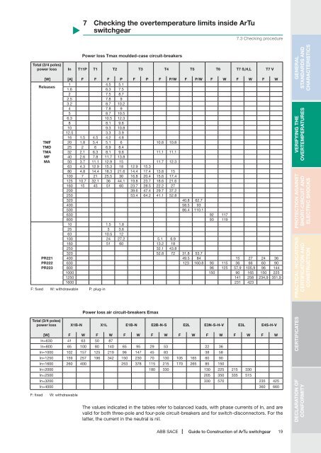
7 Checking the overtemperature limits inside <strong>ArTu</strong><strong>switchgear</strong>7.3 Checking procedurePower loss Tmax moulded-case circuit-breakersTotal (3/4 poles)power loss In T11P T1 T2 T3 T4 T5 T6 T7 S,H,L T7 V[W] [A] F F F P F P F P/W F P/W F W F W F WReleases1 4.5 5.11.6 6.3 7.52 7.5 8.72.5 7.8 93.2 8.7 10.24 7.8 95 8.7 10.56.3 10.5 12.38 8.1 9.610 9.3 10.812.5 3.3 3.916 1.5 4.5 4.2 4.8TMF 20 1.8 5.4 5.1 6 10.8 10.8TMD 25 2 6 6.9 8.4TMA 32 2.1 6.3 8.1 9.6 11.1 11.1MF 40 2.6 7.8 11.7 13.8MA 50 3.7 11.1 12.9 15 11.7 12.363 4.3 12.9 15.3 18 12.9 15.380 4.8 14.4 18.3 21.6 14.4 17.4 13.8 15100 7 21 25.5 30 16.8 20.4 15.6 17.4125 10.7 32.1 36 44.1 19.8 23.7 18.6 21.6160 15 45 51 60 23.7 28.5 22.2 27200 39.6 47.4 29.7 37.2250 53.4 64.2 41.1 52.8320 40.8 62.7400 58.5 93500 86.4 110.1630 92 117800 93 11910 1.5 1.825 3 3.663 10.5 12100 24 27.2 5.1 6.9160 51 60 13.2 18250 32.1 43.8320 52.8 72 31.8 53.7PR221 400 49.5 84 15 27 24 36PR222 630 123 160.8 90 115 36 66 60 90PR223 800 96 125 57,9 105,9 96 1441000 150 90 165 150 2251250 141 258 234,9 351,91600 231 423F: fixed W: withdrawable P: plug-inGENERALSTANDARDS ANDCHARACTERISTICSVERIFYING THEOVERTEMPERATURESPROTECTION AGAINSTSHORT-CIRCUIT ANDELECTRIC SHOCKSPRACTICAL INDICATIONSCERTIFICATION ANDCONSTRUCTIONPower loss air circuit-breakers EmaxTotal (3/4 poles)power loss X1B-N X1L E1B-N E2B-N-S E2L E3N-S-H-V E3L E4S-H-V[W] F W F W F W F W F W F W F W F WIn=630 41 63 50 87In=800 65 100 80 140 65 95 29 53 22 36In=1000 102 157 125 219 96 147 45 83 38 58In=1250 159 257 196 342 150 230 70 130 105 165 60 90In=1600 260 400 253 378 115 215 170 265 85 150In=2000 180 330 130 225 215 330In=2500 205 350 335 515In=3200 330 570 235 425In=4000 360 660F: fixed W: withdrawableThe values indicated in the tables refer <strong>to</strong> balanced loads, with phase currents <strong>of</strong> In, and arevalid for both three-pole and four-pole circuit-breakers and for switch-disconnec<strong>to</strong>rs. For thelatter, the current in the neutral is nil.CERTIFICATESDECLARATION OFCONFORMITYABB SACE <strong>Guide</strong> <strong>to</strong> <strong>Construction</strong> <strong>of</strong> <strong>ArTu</strong> <strong>switchgear</strong> 19
7 Checking the overtemperature limits inside <strong>ArTu</strong><strong>switchgear</strong>7.3 Checking procedureGENERALSTANDARDS ANDCHARACTERISTICSVERIFYING THEOVERTEMPERATURESDistribution busbarsThe busbars present in the column being examined must be considered in the dissipatedpower calculation.The length can be calculated approximately by inspecting the front <strong>of</strong> the <strong>switchgear</strong>.The power dissipated by the busbars can be determined by means <strong>of</strong> the following relation:Where:2IP (I b ) = P (I n )(b. LI n)piece. 3P (I n) is the dissipated power per unit <strong>of</strong> length at the rated current and its value can betaken from table B.2 <strong>of</strong> the IEC 60890 Standard given below, or from the manufacturer’scatalogues.(L piece. 3) is the length <strong>of</strong> the piece <strong>of</strong> busbar which passes through the column beingexamined, multiplied by 3 as it is a three-phase circuit.Table B.2 <strong>of</strong> the IEC 60890 Standard was used for the calculations in this document, consideringan air temperature <strong>of</strong> 55°C around the busbar.PROTECTION AGAINSTSHORT-CIRCUIT ANDELECTRIC SHOCKSOperating current and dissipated powers <strong>of</strong> the bare busbars, with vertical layout, without directconnections <strong>to</strong> the apparatusLengthxthicknessCrosssection(Cu)Maximum admissible conduc<strong>to</strong>r temperature: 85 °CAir temperature around the conduc<strong>to</strong>rsinside the housing: 35 °Cfrom 50 Hz at 60 Hz ACDC and AC up <strong>to</strong>16 2/3 HzAir temperature around the conduc<strong>to</strong>rsinside the housing: 55 °Cfrom 50 Hz at 60 Hz AC DC and AC up <strong>to</strong> 16 2/3 HzPRACTICAL INDICATIONSCERTIFICATION ANDCONSTRUCTIONCERTIFICATESDECLARATION OFCONFORMITYmm x mm12 x 215 x 215 x 320 x 220 x 320 x 520 x 1025 x 530 x 530 x 1040 x 540 x 1050 x 550 x 1060 x 560 x 1080 x 580 x 10100 x 5100 x 10120 x 10operating currentdissipated powers (1)mm 2 A* W/m23,529,544,539,559,599,119912414929919939924949929959939979949999912001441702152152713645684355047626419517751133915131011701649143619822314* one conduc<strong>to</strong>r per phase19,521,723,126,127,629,936,934,138,444,447,052,755,760,964,168,580,785,0100,1101,7115,5operating currentA**2422823753514636651097779894141011121716132220081530228819292806230132983804dissipated powers (1)W/m27,529,935,234,840,249,869,255,460,677,972,588,982,9102,994,2116,2116,4138,7137,0164,2187,3operating currentdissipated powers (1)A* W/m144170215215271364569435505770644968782116492613571200174214762128251419,521,723,126,127,629,936,734,138,244,847,052,655,461,464,769,580,885,198,7102,6115,9operating currentA**242282375354463668110778899143611281796135721411583248720353165240738444509** two conduc<strong>to</strong>rs per phasedissipated powers (1)W/m27,529,935,235,440,250,369,655,660,777,872,390,583,4103,894,6117,8116,1140,4121,2169,9189,9operating currentdissipated powers (1)A* W/m105124157157198266414317368556468694566826667955858120310481445168810,411,612,313,914,716,019,618,120,527,725,028,129,732,334,136,442,945,353,354,061,5operating currentA**1772062742563384858005686521028811125196414651116166814072047167824062774(1) single lengthdissipated powers (1)W/m14,716,018,818,521,426,536,829,532,341,438,547,344,154,850,162,061,973,872,984,499,6operating currentdissipated powers (1)A* W/m105124157157198266415317369562469706570849675989875127110771552183310,411,612,312,314,716,019,518,120,423,924,928,029,432,734,436,942,945,352,554,661,6operating currentA**1772062742583384878075726561048586131098915621154181414841756175628033288dissipated powers (1)W/m14,716,018,818,821,426,737,029,532,341,538,548,144,355,350,362,761,874,869,890,4101,020 ABB SACE<strong>Guide</strong> <strong>to</strong> <strong>Construction</strong> <strong>of</strong> <strong>ArTu</strong> <strong>switchgear</strong>