OPERATION OF THE SOLEIL RF SYSTEM
OPERATION OF THE SOLEIL RF SYSTEM
OPERATION OF THE SOLEIL RF SYSTEM

You also want an ePaper? Increase the reach of your titles
YUMPU automatically turns print PDFs into web optimized ePapers that Google loves.
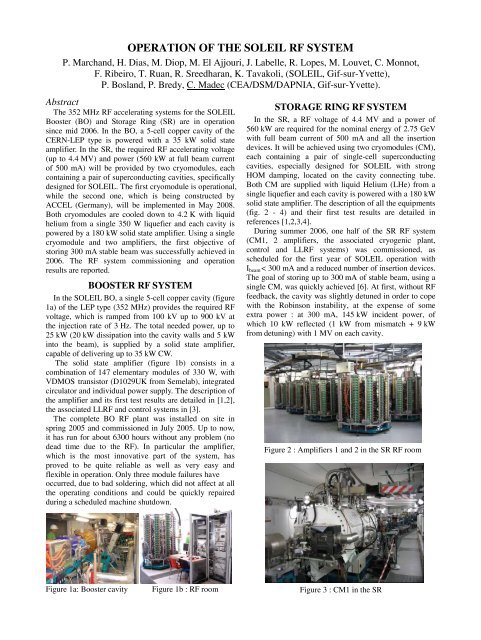
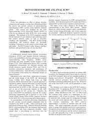
<strong>OPERATION</strong> <strong>OF</strong> <strong>THE</strong> <strong>SOLEIL</strong> <strong>RF</strong> <strong>SYSTEM</strong>P. Marchand, H. Dias, M. Diop, M. El Ajjouri, J. Labelle, R. Lopes, M. Louvet, C. Monnot,F. Ribeiro, T. Ruan, R. Sreedharan, K. Tavakoli, (<strong>SOLEIL</strong>, Gif-sur-Yvette),P. Bosland, P. Bredy, C. Madec (CEA/DSM/DAPNIA, Gif-sur-Yvette).AbstractThe 352 MHz <strong>RF</strong> accelerating systems for the <strong>SOLEIL</strong>Booster (BO) and Storage Ring (SR) are in operationsince mid 2006. In the BO, a 5-cell copper cavity of theCERN-LEP type is powered with a 35 kW solid stateamplifier. In the SR, the required <strong>RF</strong> accelerating voltage(up to 4.4 MV) and power (560 kW at full beam currentof 500 mA) will be provided by two cryomodules, eachcontaining a pair of superconducting cavities, specificallydesigned for <strong>SOLEIL</strong>. The first cryomodule is operational,while the second one, which is being constructed byACCEL (Germany), will be implemented in May 2008.Both cryomodules are cooled down to 4.2 K with liquidhelium from a single 350 W liquefier and each cavity ispowered by a 180 kW solid state amplifier. Using a singlecryomodule and two amplifiers, the first objective ofstoring 300 mA stable beam was successfully achieved in2006. The <strong>RF</strong> system commissioning and operationresults are reported.BOOSTER <strong>RF</strong> <strong>SYSTEM</strong>In the <strong>SOLEIL</strong> BO, a single 5-cell copper cavity (figure1a) of the LEP type (352 MHz) provides the required <strong>RF</strong>voltage, which is ramped from 100 kV up to 900 kV atthe injection rate of 3 Hz. The total needed power, up to25 kW (20 kW dissipation into the cavity walls and 5 kWinto the beam), is supplied by a solid state amplifier,capable of delivering up to 35 kW CW.The solid state amplifier (figure 1b) consists in acombination of 147 elementary modules of 330 W, withVDMOS transistor (D1029UK from Semelab), integratedcirculator and individual power supply. The description ofthe amplifier and its first test results are detailed in [1,2],the associated LL<strong>RF</strong> and control systems in [3].The complete BO <strong>RF</strong> plant was installed on site inspring 2005 and commissioned in July 2005. Up to now,it has run for about 6300 hours without any problem (nodead time due to the <strong>RF</strong>). In particular the amplifier,which is the most innovative part of the system, hasproved to be quite reliable as well as very easy andflexible in operation. Only three module failures haveoccurred, due to bad soldering, which did not affect at allthe operating conditions and could be quickly repairedduring a scheduled machine shutdown.STORAGE RING <strong>RF</strong> <strong>SYSTEM</strong>In the SR, a <strong>RF</strong> voltage of 4.4 MV and a power of560 kW are required for the nominal energy of 2.75 GeVwith full beam current of 500 mA and all the insertiondevices. It will be achieved using two cryomodules (CM),each containing a pair of single-cell superconductingcavities, especially designed for <strong>SOLEIL</strong> with strongHOM damping, located on the cavity connecting tube.Both CM are supplied with liquid Helium (LHe) from asingle liquefier and each cavity is powered with a 180 kWsolid state amplifier. The description of all the equipments(fig. 2 - 4) and their first test results are detailed inreferences [1,2,3,4].During summer 2006, one half of the SR <strong>RF</strong> system(CM1, 2 amplifiers, the associated cryogenic plant,control and LL<strong>RF</strong> systems) was commissioned, asscheduled for the first year of <strong>SOLEIL</strong> operation withI beam < 300 mA and a reduced number of insertion devices.The goal of storing up to 300 mA of stable beam, using asingle CM, was quickly achieved [6]. At first, without <strong>RF</strong>feedback, the cavity was slightly detuned in order to copewith the Robinson instability, at the expense of someextra power : at 300 mA, 145 kW incident power, ofwhich 10 kW reflected (1 kW from mismatch + 9 kWfrom detuning) with 1 MV on each cavity.Figure 2 : Amplifiers 1 and 2 in the SR <strong>RF</strong> roomFigure 1a: Booster cavityFigure 1b : <strong>RF</strong> roomFigure 3 : CM1 in the SR
The injection at constant tuning and ramped voltage isnow routinely used in operation. A software application,programmed in the PLC dedicated to the <strong>RF</strong> control, setthe cavity voltage and phase as a function of the storedbeam current.First <strong>RF</strong> operational experienceCryogenic plant [4]At the beginning of the commissioning, difficultieswere encountered with the cryogenic system, in particularwith pressure instabilities inside the cavity He tank, dueto thermal oscillations. This was solved after bringing inslight modifications on the cryogenic valve box. Thesystem has then become very reliable and the pressurevariations could be kept below ± 2 mbar, namely ± 0.1° inphase. A few shutdowns, triggered by utility losses (wateror electrical), have demonstrated the ability of the systemto recover within a short time.Cryomodules [1,5]The conditioning of the cavities and their powercouplers with beam went quite smoothly. A few couplervacuum trips occurred at first when reaching power largerthan 150 kW per cavity. Some further conditioning likelyis required for operating at such power level. However,with proper settings, the power does not exceed 145 kWper cavity at 300 mA with a single CM, which is moredemanding than reaching 500 mA with 2 CM.Another successful result is that, there was no evidenceof cavity HOM excitation, up to 300 mA. The powerdissipation in the HOM loads always remained negligibleand the residual beam phase oscillations below 0.1° rms.As already reported, we took care of using the cavitytuners more sparingly. Moreover, we have recentlyimplemented a rev counter aimed at detecting earlypossible missing motor steps which are signs heralding asticking.The second cryomodule is being fabricated by ACCELGmbH. The two cavities were successfully tested atCERN in vertical cryostat (figure 8). The implementationof the complete CM2 in the SR is scheduled in May 2008.Figure 8 : Q0 vs. Eacc [MV/m] for the 2 first cavitiesAmplifiers [2]The two 180 kW solid state amplifiers for CM1 havedemonstrated their good reliability and flexibility inoperation. Up to date, they are not yet liable for any lossof beam time. The 1450 amplifier modules were suppliedby BBEF - Beijing, integrating LR301 transistors fromPolyfet. Although it was not perturbing for the operation,24 transistor failures occurred after 4835 running hours, ata failure rate which is decreasing with time. The statisticsis not yet sufficient to find out what comes from the infantmortality and what is the actual MTBF; longer runningperiods are required for that. The 100 available sparemodules will enable to make a turn over : 50 usable inhouse while 50 are under repair.Investigations of other suitable transistors are going on:samples of the BLF369, newly developed by Philips, arebeing tested and the first results are quite promising; thatcould be an interesting alternative.Concerning the amplifiers 3 and 4 for the CM2, 6 of the8 required 45 kW towers are already completed.LL<strong>RF</strong> and controls [3]With the fully analogue LL<strong>RF</strong>, presently in use, we canachieve a cavity voltage stability of ± 0.5 % in amplitudeand 0.15° in phase without <strong>RF</strong> feedback and ± 0.1% and0.05° with the <strong>RF</strong> feedback, respectively.A fast digital FPGA based I/Q feedback, is currentlyunder development; the first prototype is completed andshould be tested in the real environment in forthcomingruns dedicated to machine development.CONCLUSIONUp to date, the BO and one half of SR <strong>RF</strong> plants havebeen commissioned and the first operational experience isfully satisfactory. After 6300 running hours in the BO(4835 in the SR), they proved to be very reliable andflexible in operation.Special emphasis is put on the success of the solid stateamplifiers, which were the most challenging part of thesystem; they are not yet liable for any loss of beam time.Several laboratories have expressed their intention ofadopting the solid state technology “à la <strong>SOLEIL</strong>”.Collaboration agreements for the transfer of technologyare under elaboration.The second half of the SR <strong>RF</strong> system, which is underfabrication, will be implemented in May 2008 forreaching the nominal performance (4.4 MV and 500 mA).ACKNOWLEDGEMENTThe authors would like to thank all the members ofCEA, CNRS, CERN, ES<strong>RF</strong> and <strong>SOLEIL</strong> who contributedto the success of this project.REFERENCES[1] P. Marchand et al, Proc. of EPAC06, p. 384.[2] P. Marchand et al, SOU-<strong>RF</strong>-NT-2210, June 2007.[3] P. Marchand et al, Proc. of EPAC06, p. 1447.[4] M. Louvet et al, Proc. S<strong>RF</strong>2005, ThP42.[5] C. Thomas-Madec et al, Proc. S<strong>RF</strong>2005, ThP45.[6] A. Nadji et al, TUPMN009, this conference.[7] M. Svandrlik, private communication.[8] P. Marchand, 10 th ESLS <strong>RF</strong> Meeting, DELTA,Dortmund, 27 – 28 th Sept. 2006. http://athene.delta.unidortmund.de/esls-rf/talks/07_Marchand.pdf

![å¨åæãæç©ä¿æ¤ææå¦ãï¼å¤§äºï¼ââå åºææååºç¨.ppt [å
¼å®¹æ¨¡å¼]](https://img.yumpu.com/42555314/1/190x135/aaaeaaeccaaeaeaea-ai-1-4-aai-1-4-aaa-aaeaeaacppt-a-1-4-araea-1-4-.jpg?quality=85)