bcp system for the anl-fnal scspf
bcp system for the anl-fnal scspf
bcp system for the anl-fnal scspf

Create successful ePaper yourself
Turn your PDF publications into a flip-book with our unique Google optimized e-Paper software.
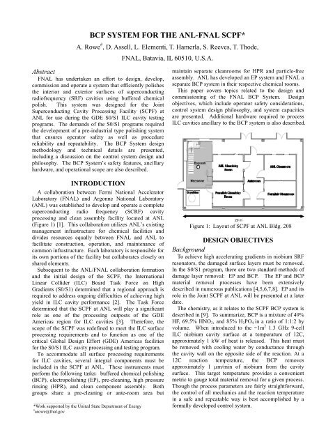
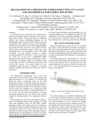
BCP SYSTEM FOR THE ANL-FNAL SCPF*A. Rowe # , D. Assell, L. Elementi, T. Hamerla, S. Reeves, T. Thode,FNAL, Batavia, IL 60510, U.S.A.AbstractFNAL has undertaken an ef<strong>for</strong>t to design, develop,commission and operate a <strong>system</strong> that efficiently polishes<strong>the</strong> interior and exterior surfaces of superconductingradiofrequency (SRF) cavities using buffered chemicalpolish. This <strong>system</strong> was designed <strong>for</strong> <strong>the</strong> JointSuperconducting Cavity Processing Facility (SCPF) atANL <strong>for</strong> use during <strong>the</strong> GDE S0/S1 ILC cavity testingprograms. The demands of <strong>the</strong> S0/S1 programs required<strong>the</strong> development of a pre-industrial type polishing <strong>system</strong>that ensures operator safety as well as procedurereliability and repeatability. The BCP System designmethodology and technical details are presented,including a discussion on <strong>the</strong> control <strong>system</strong> design andphilosophy. The BCP System’s safety features, ancillaryhardware, and operational scope are also described.INTRODUCTIONA collaboration between Fermi National AcceleratorLaboratory (FNAL) and Argonne National Laboratory(ANL) was established to develop and operate a completesuperconducting radio frequency (SCRF) cavityprocessing and clean assembly facility located at ANL(Figure 1) [1]. This collaboration utilizes ANL’s existingmanagement infrastructure <strong>for</strong> chemical facilities anddivides resources equally between FNAL and ANL tofacilitate construction, operation, and maintenance ofcommon infrastructure. Each laboratory is responsible <strong>for</strong>its own portions of <strong>the</strong> facility but collaborates closely onshared elements.Subsequent to <strong>the</strong> ANL/FNAL collaboration <strong>for</strong>mationand <strong>the</strong> initial design of <strong>the</strong> SCPF, <strong>the</strong> InternationalLinear Collider (ILC) Board Task Force on HighGradients (S0/S1) determined that a regional approach isrequired to address ongoing difficulties of achieving highyield in ILC cavity per<strong>for</strong>mance [2]. The Task Forcedetermined that <strong>the</strong> SCPF at ANL will play a significantrole as one of <strong>the</strong> processing outposts of <strong>the</strong> GDEAmericas region <strong>for</strong> ILC cavities [3]. There<strong>for</strong>e, <strong>the</strong>scope of <strong>the</strong> SCPF was redefined to meet <strong>the</strong> ILC surfaceprocessing requirements and to function as one of <strong>the</strong>critical Global Design Ef<strong>for</strong>t (GDE) Americas facilities<strong>for</strong> <strong>the</strong> S0/S1 ILC cavity processing and testing program.To accommodate all surface processing requirements<strong>for</strong> ILC cavities, several integral components must beincluded in <strong>the</strong> SCPF at ANL. These instruments mustper<strong>for</strong>m <strong>the</strong> following tasks: buffered chemical polishing(BCP), electropolishing (EP), pre-cleaning, high pressurerinsing (HPR), and clean component assembly. Bothgroups share a pre-cleaning or ante-room area but___________________________________________*Work supported by <strong>the</strong> United State Department of Energy# arowe@<strong>fnal</strong>.govmaintain separate cleanrooms <strong>for</strong> HPR and particle-freeassembly. ANL has developed an EP <strong>system</strong> and FNAL aseparate BCP <strong>system</strong> in <strong>the</strong>ir respective chemical rooms.This paper covers topics related to <strong>the</strong> design andcommissioning of <strong>the</strong> FNAL BCP System. Designobjectives, which include operator safety considerations,control <strong>system</strong> design philosophy, and <strong>system</strong> capacitiesare presented. Additional hardware required to processILC cavities ancillary to <strong>the</strong> BCP <strong>system</strong> is also described.20 mFigure 1: Layout of SCPF at ANL Bldg. 208DESIGN OBJECTIVESBackgroundTo achieve high accelerating gradients in niobium SRFresonators, <strong>the</strong> damaged surface layers must be removed.In <strong>the</strong> S0/S1 program, <strong>the</strong>re are two standard methods ofdamage layer removal: EP and BCP. The EP and BCPmaterial removal processes have been extensivelydescribed in numerous publications [4,5,6,7,8]. EP and itsrole in <strong>the</strong> Joint SCPF at ANL will be presented at a laterdate.The chemistry, as it relates to <strong>the</strong> SCPF BCP <strong>system</strong> isdescribed in [9]. To summarize, BCP is a mixture of 49%HF, 69.5% HNO 3 , and 85% H 3 PO 4 in a ratio of 1:1:2 byvolume. When introduced to <strong>the</strong> ~1m 2 1.3 GHz 9-cellILC niobium cavity surface at a temperature of 12C,approximately 1 kW of heat is released. This heat mustbe removed with cooling water by conductance through<strong>the</strong> cavity wall on <strong>the</strong> opposite side of <strong>the</strong> reaction. At a12C reaction temperature, <strong>the</strong> BCP removesapproximately 1 µm/min of niobium from <strong>the</strong> cavitysurface. This target temperature provides a convenientmetric to gauge total material removal <strong>for</strong> a given process.Though <strong>the</strong> process parameters are fairly straight<strong>for</strong>ward,<strong>the</strong> control of all mechanics and <strong>the</strong> reaction temperaturein a safe and repeatable way is best accomplished by a<strong>for</strong>mally developed control <strong>system</strong>.
A description of <strong>the</strong> original controls <strong>system</strong> <strong>for</strong> <strong>the</strong>BCP <strong>system</strong> is covered in [10]. The modifications andimprovements to <strong>the</strong> original control <strong>system</strong> have beenimplemented and are presented in this paper.The BCP System <strong>for</strong> <strong>the</strong> ILC S0/S1 processing programwill be primarily used to remove <strong>the</strong> contaminants on <strong>the</strong>outside cavity surfaces to prevent fouling of <strong>the</strong> interiorsurfaces during <strong>the</strong> hydrogen degasification bake cycle.Until large grain and single-crystal cavity productionmatures, <strong>the</strong> relevancy of processing <strong>the</strong> inside surfaces offine-grain ILC cavities <strong>for</strong> vertical per<strong>for</strong>mance testing atvery high fields (>25MV/m) is limited due to <strong>the</strong> BCPquench field limit well below that of EP. However, BCPprocessing on large-grain and single crystal cavities hasshown great promise as a replacement <strong>for</strong> EP [11]. TheBCP System will play a significant role in provingwhe<strong>the</strong>r multi-cell large-grain or single crystal cavityprocessing can eliminate EP from <strong>the</strong> processing sequence.For <strong>the</strong> near future, <strong>the</strong> role of <strong>the</strong> BCP System will be toprovide external surface polishing of S0/S1 cavities andinternal polishing on o<strong>the</strong>r 1.3 GHz cavities not in <strong>the</strong>S0/S1 program.IndustrializationOne of <strong>the</strong> BCP System’s fundamental design preceptswas to build a tool with features attractive to industry.High volume cavity surface processing will need toolsthat are safe and easy to use with robust design whichallow quick change between operations. The BCP Systemdesign accomplished <strong>the</strong>se goals by focusing on operatortooling and controls <strong>system</strong>. These features are easilyduplicated in any BCP System constructed in <strong>the</strong> future.The BCP System design is modular in that many shapesand sizes of cavities can be processed without makingmodifications to <strong>the</strong> BCP System itself as long as <strong>the</strong>processed surfaces are within <strong>the</strong> capacity of <strong>the</strong> <strong>system</strong>.Each cavity type requires its own tooling (jackets, holdingfixtures, etc.), but <strong>the</strong> connections to <strong>the</strong> BCP System and<strong>the</strong> method in which <strong>the</strong> process takes place are <strong>the</strong> same.SafetyProcesses that use concentrated HF require extremeuser caution and tight procedure control. At ANL, a<strong>for</strong>mal safety program at <strong>the</strong> SCPF has been implementedthat dictates proper HF handling techniques, appropriatepersonal protective equipment, and emergency responseprocedures. Any operation utilizing HF or o<strong>the</strong>rconcentrated acids must obey <strong>the</strong> approved SCPFumbrella safety documents. In addition to <strong>the</strong> umbrellasafety documents, setup, operation, and shutdownprocedures are all controlled via checklist. This checklistensures all proper precautions specific to <strong>the</strong> proceduresare taken.The BCP System was designed to limit <strong>the</strong> BCP (HF)handling and contact opportunity to an absolute minimum.At no time does an operator physically manipulate <strong>the</strong>BCP o<strong>the</strong>r than when rolling BCP supply drums enclosedin secondary overpack containers. During routineoperation, <strong>the</strong> only opportunity <strong>for</strong> contact is duringfitting disconnection after a procedure. All fluid (BCP,Figure 2: BCP System flow schematic. Operator GUI screen capture.safety and implementing uncomplicated flow mechanics,cooling water, dilute waste) manipulation is per<strong>for</strong>med by
programmable logic controller (PLC) controlled flowmechanics. Should leaks in <strong>the</strong> plumbing occur, all likelyareas reside within secondary containment.Operator exposure to dilute waste is also extremelylimited. All dilute waste generated during a procedure isneutralized and pumped to a drain by an automatedneutralization <strong>system</strong>. Operator involvement in aprocedure is limited to connecting <strong>the</strong> cavity to <strong>the</strong> BCPSystem, stinging BCP drums, and running <strong>the</strong> procedureremotely from a control center located outside <strong>the</strong>chemistry room.Process ControlThe fluid flow mechanics are required to handle BCP,ultra pure water <strong>for</strong> rinsing and cooling, and dilute wastesimultaneously. Expecting an operator to manipulate<strong>the</strong>se fluids with numerous valve openings and closingsand pump activation and deactivation while monitoringseveral sensors is unreasonable in a process that issensitive to so many variables. There<strong>for</strong>e, a PLC andsoftware interface with a PC was chosen to per<strong>for</strong>m <strong>the</strong>seoperations. An operator is expected to key into <strong>the</strong>interface <strong>the</strong> procedure to be per<strong>for</strong>med, move <strong>the</strong>processes from one step to <strong>the</strong> next, and verify that <strong>the</strong>control <strong>system</strong> is responding to all sensors as needed.DESIGN DETAILSBCP and Neutralization SystemsThe fluid mechanics are divided into separatesub<strong>system</strong>s <strong>for</strong> BCP and cooling water flow. The BCPSystem flow schematic is shown in Figure 2 with <strong>the</strong>cooling water loop shown on <strong>the</strong> right and <strong>the</strong> BCP loopon <strong>the</strong> left. The separate loops do not share like plumbingwhich prevents inadvertent mixing of acid and water. Thesub<strong>system</strong>s meet at <strong>the</strong> cavity/jacket but are separated by<strong>the</strong> resonator wall. The cavity is enclosed in an etchingjacket and connected to five separate lines: BCP supplyand return, cooling water supply and return, and coolingwater overflow.The water cooling loop receives water from a gravityfeed tank which is automatically pre-filled be<strong>for</strong>e aprocedure begins. The cooling loop includes plumbingand pumps between a heat exchanger and <strong>the</strong> etchingjacket. The water flows on <strong>the</strong> opposite side of <strong>the</strong> etchprocess <strong>the</strong>reby removing <strong>the</strong> reaction heat. The reactionheat carried away by <strong>the</strong> water is removed from <strong>the</strong>cooling loop in a plate and frame heat exchanger. Anexternal chiller supplies <strong>the</strong> heat exchanger with 6C to10C chilled water. This double heat exchangearrangement prevents acid from escaping <strong>the</strong> chemistryroom to <strong>the</strong> primary chiller in <strong>the</strong> event of a leak between<strong>the</strong> etching jacket and cavity.BCP is supplied to <strong>the</strong> process via direct pumping froma pre-cooled drum. The BCP flows from <strong>the</strong> supply drumthrough <strong>the</strong> cavity and back to <strong>the</strong> drum. At <strong>the</strong>conclusion of <strong>the</strong> etching process, <strong>the</strong> BCP in <strong>the</strong> cavityand <strong>system</strong> plumbing flows into an acid dump tank whichresides below <strong>the</strong> process. The acid is immediatelypumped into <strong>the</strong> process supply drum. Once <strong>the</strong> cavity isfree of BCP, ultrapure water (UPW) from <strong>the</strong> gravity feedtank flushes through <strong>the</strong> <strong>system</strong> <strong>the</strong>reby rinsing <strong>the</strong> cavityand all lines that carry acid. The dilute waste generateddumps into a dilute waste tank next to <strong>the</strong> acid dump tank.The rinse cycles continue until <strong>the</strong> dilute waste reaches apH of 4 or higher as measured by a pH sensor located in<strong>the</strong> dilute waste tank. All of <strong>the</strong> dilute waste is pumpedfrom <strong>the</strong> tank to <strong>the</strong> automated neutralization <strong>system</strong>.The neutralization <strong>system</strong> contains a 95 gallon storagetank, 10 gpm recirculation pump, and metering pump thatdoses liquid NaOH into <strong>the</strong> tank. Redundant pH sensorsin line with <strong>the</strong> recirculation pump communicate with <strong>the</strong>PLC which ‘tells’ <strong>the</strong> metering pump to dose caustic into<strong>the</strong> tank until <strong>the</strong> pH of <strong>the</strong> dilute waste is above 5 – alevel safe to dump into <strong>the</strong> ANL sewage <strong>system</strong>. Noconcentrated acid is neutralized.All materials used to construct <strong>the</strong> BCP andneutralization <strong>system</strong>s are approved <strong>for</strong> HF handling.PVDF, Teflon, fluorinated Viton, and PFA are commonmaterials suitable <strong>for</strong> HF. Where possible, bead andcrevice free PVDF tube welding was employed tominimize <strong>the</strong> number of fittings. All valves and pumpsare certified <strong>for</strong> HF as well as o<strong>the</strong>r acids.The BCP System is shown in three photos in Figure 3as installed. The left photo is <strong>the</strong> neutralization <strong>system</strong>and its secondary containment. The center photo shows<strong>the</strong> BCP <strong>system</strong> and PVC test vessel. The right photoshows local ventilation hoods installed to capture processfumes released at <strong>the</strong> BCP supply drum that residesbeneath <strong>the</strong> hood openings.Figure 3: Neutralization <strong>system</strong>, BCP System, andventilation ductwork.Ventilation SystemRemoving process fumes (NO x , HF vapor) is critical tosafe operation. The ventilation <strong>system</strong> was designed tocapture fumes at <strong>the</strong> source, or potential source in <strong>the</strong> caseof leaks. All plumbing and vessels are located in a largeframe covered by a Lexan skin. The Lexan skin <strong>for</strong>ms afume hood with <strong>the</strong> draft created by a large suctionmanifold located at <strong>the</strong> top surface of <strong>the</strong> frame. TheBCP System plumbing was enclosed in a fume hood notto capture process fumes but to ga<strong>the</strong>r fumes frompossible leaks. Should a leak occur, an operator cansafely neutralize it without <strong>the</strong> risk of fume exposure.
The process fumes are released at <strong>the</strong> supply drum.Since <strong>the</strong> acid loop is sealed except at <strong>the</strong> drum stingerports, all fumes will escape from <strong>the</strong> ports ra<strong>the</strong>r than at<strong>the</strong> reaction location. Localized hoods at <strong>the</strong> surface of<strong>the</strong> supply drums remove <strong>the</strong> process fumes and give <strong>the</strong>operator a safe location to open overpacks and sting BCPdrums.The last direct fume removal locations are at <strong>the</strong> acidand dilute waste tanks. Direct venting of <strong>the</strong>se tankskeeps <strong>the</strong> chemistry room fume concentration well belowwhat is allowed <strong>for</strong> safe entry even if a leak occurs.All fumes removed by <strong>the</strong> ventilation <strong>system</strong> are treatedin a 3000cfm scrubber that services both SCPF chemistryrooms. When necessary, 90% of <strong>the</strong> scrubber capacitycan be locally channeled to any of <strong>the</strong> duct locations in<strong>the</strong> chemistry room.Control SystemThe control <strong>system</strong> operates and monitors 26 valves, 6pumps, 6 pH sensors, 5 flow meters, 5 temperature gauges,2 resistivity sensors, and 4 level indicators. A PLC witha PC graphical user interface (GUI) monitors all sensorsand manipulates <strong>the</strong> pneumatic valves and pumps during aprocedure. Though <strong>the</strong> BCP procedure is uncomplicated,<strong>the</strong> amount of hardware required to per<strong>for</strong>m <strong>the</strong> mixing,etching, and rinsing operations is substantial. A PLCprovides <strong>the</strong> most reliable means to per<strong>for</strong>m all <strong>system</strong>aticmonitoring operations.An etching procedure is divided into several main steps.These steps are BCP mixing, filling, polishing, andrinsing. A semi-automated controls approach cues <strong>the</strong>operator to move to <strong>the</strong> next process step upon completionof <strong>the</strong> prior operation. This approach allows <strong>the</strong> operatorto monitor <strong>the</strong> progress of each step without having toworry about <strong>the</strong> pump and valve actuation sequence. ThePLC ‘watches’ all sensors and in<strong>for</strong>ms <strong>the</strong> operator of<strong>system</strong> status via <strong>the</strong> GUI. All sensor data is logged andtime stamped to include in cavity travelers and <strong>for</strong> futurereference.Should a problem in <strong>the</strong> procedure occur, <strong>the</strong> PLC isprogrammed to not only respond to <strong>the</strong> problem, but alsoin<strong>for</strong>m <strong>the</strong> operator of <strong>the</strong> error. The operator always has<strong>the</strong> option of hitting a hard-wired manual override stopbutton that automatically dumps <strong>the</strong> acid into <strong>the</strong> aciddump tank. The control <strong>system</strong> is insensitive to poweroutages or loss in air pressure. Redundant power suppliesand backup compressed air tanks were implemented toprevent lengthy procedure stoppages during failures ofei<strong>the</strong>r of <strong>the</strong>se <strong>system</strong>s.A recipe <strong>for</strong>mat was adopted to facilitate processing avariety of cavity types and sizes with <strong>the</strong> BCP System.Each cavity type and procedure length as well as o<strong>the</strong>rparameters are defined in <strong>the</strong> recipes. At <strong>the</strong> beginning ofa procedure, <strong>the</strong> operator chooses or modifies a recipe and<strong>the</strong> PLC will run <strong>the</strong> step routines accordingly.Ancillary HardwareBare cavities cannot be processed with BCP withoutspecial hardware. The hardware designed and fabricated<strong>for</strong> use in <strong>the</strong> SCPF includes two etching jackets (outsideand inside) <strong>for</strong> 1.3 GHz 9-cell ILC cavities, a chemicallyresistant transport cart, and handling tooling that grabs <strong>the</strong>etching jackets.The etching jackets are an interface between <strong>the</strong> BCPSystem and <strong>the</strong> cavity. The jacket acts as a container thatprotects <strong>the</strong> cavity as well as provides a means to cool <strong>the</strong>process during a polishing procedure. The jackets areconstructed primarily of PVDF and sealed with Viton o-rings. The jacket is installed vertically and held toge<strong>the</strong>rwith De-Sta-Co style clamps. Sanitary quick-type clampsare used to make all fluid connections. A 3-D image of<strong>the</strong> outside surface etching jacket is shown in Figure 4.Figure 4: 1.3 GHz 9-cell cavity outside etching jacket.A chemically resistant transport cart with 500lbcapacity was specified and purchased. This cart iscapable of hoisting a 9-cell ILC cavity installed in anetching jacket filled with water and BCP. Tooling thatallows <strong>the</strong> cart to grab <strong>the</strong> cavity and jacket was designedand is currently in production. The cavity transport cartand tooling are shown in Figure 5.Figure 5: Transport cart holding cavity with andwithout etching jacket.CONCLUSIONBCP processing at <strong>the</strong> SCPF at ANL is nearly a reality.The BCP System is designed and assembled and being
commissioned. The control <strong>system</strong> and recipeprogramming <strong>for</strong> 9-cell ILC cavities is nearly complete.The last remaining hardware is in procurement and will bearriving shortly. With all developmental elementsconverging simultaneously, <strong>the</strong> only remaining hurdle is<strong>the</strong> ANL safety review that will cover <strong>the</strong> operation of <strong>the</strong>BCP System. A successful safety review will give <strong>the</strong>Joint SCPF a full cadre of chemistry capability.ACKNOWLEDGEMENTSThe author would like to thank <strong>the</strong> co-authors as well asDirk Hurd <strong>for</strong> <strong>the</strong>ir significant ef<strong>for</strong>t at getting BCPcapability going in <strong>the</strong> SCPF. Also, Y. Terechkine and C.Boffo must be commended <strong>for</strong> <strong>the</strong> initial layout of <strong>the</strong>BCP System.REFERENCES[1] K. Shepard, et al., “Addendum to ANL/FNALMemorandum of Understanding <strong>for</strong> SCSPFOperation”, ANL/FNAL Directorate, April 2006.[2] H. Hayano, et al., “ILC R&D Board Task Force onHigh Gradients (S0/S1)--Charge and Definition ofGoals”, http://www.linearcollider.org/wiki, July 2006.[3] H. Hayano, et al., “ILC R&D Board Task Force onHigh Gradients (S0/S1)—Draft Workplan 2007 <strong>for</strong>S0-‘Improving <strong>the</strong> Per<strong>for</strong>mance in Tight LoopExperiments’”, http://www.linearcollider.org/wiki/,Sept. 2006.[4] H. Padamsee, et. al., RF Superconductivity <strong>for</strong>Accelerators, John Wiley & Sons, Inc., New York,NY, 1998.[5] D. Bloess, “Chemisty and Surface Treatment,” SRF-84, Geneva, Proceedings, July 1984, pp. 409-425.[6] K. Saito, et al., “Superiority of Electropolishing overChemical Polishing on High Gradients”, SRF-97,Italy, 1997, Proceedings, pp. 795-813.[7] D. Bloess, “Preparation and Handling of Surfaces <strong>for</strong>Superconducing RF Cavities”, SRF-88, ANL, USA,Sept. 1988, pp. 359-366.[8] P. Kneisel, “Surface Preparation of Niobium”, SRF-01, Karlsruhe, July 1980, pp. 27-40.[9] Y. Terechkine, et al., “BCP Processing Facility”,SRF2003, Lubeck, Sept. 2003.[10] C. Boffo, et al., “Control System <strong>for</strong> <strong>the</strong> BCPProcessing Facility at FNAL”, SRF2003, Lubeck,Sept. 2003.[11] P. Kneisel, et. al., “Per<strong>for</strong>mance of Large Grain andSingle Crystal Niobium Cavities”, SRF2005, Ithaca,July 2005.

![å¨åæãæç©ä¿æ¤ææå¦ãï¼å¤§äºï¼ââå åºææååºç¨.ppt [å
¼å®¹æ¨¡å¼]](https://img.yumpu.com/42555314/1/190x135/aaaeaaeccaaeaeaea-ai-1-4-aai-1-4-aaa-aaeaeaacppt-a-1-4-araea-1-4-.jpg?quality=85)