bcp system for the anl-fnal scspf
bcp system for the anl-fnal scspf
bcp system for the anl-fnal scspf

Create successful ePaper yourself
Turn your PDF publications into a flip-book with our unique Google optimized e-Paper software.
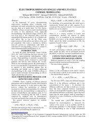
The process fumes are released at <strong>the</strong> supply drum.Since <strong>the</strong> acid loop is sealed except at <strong>the</strong> drum stingerports, all fumes will escape from <strong>the</strong> ports ra<strong>the</strong>r than at<strong>the</strong> reaction location. Localized hoods at <strong>the</strong> surface of<strong>the</strong> supply drums remove <strong>the</strong> process fumes and give <strong>the</strong>operator a safe location to open overpacks and sting BCPdrums.The last direct fume removal locations are at <strong>the</strong> acidand dilute waste tanks. Direct venting of <strong>the</strong>se tankskeeps <strong>the</strong> chemistry room fume concentration well belowwhat is allowed <strong>for</strong> safe entry even if a leak occurs.All fumes removed by <strong>the</strong> ventilation <strong>system</strong> are treatedin a 3000cfm scrubber that services both SCPF chemistryrooms. When necessary, 90% of <strong>the</strong> scrubber capacitycan be locally channeled to any of <strong>the</strong> duct locations in<strong>the</strong> chemistry room.Control SystemThe control <strong>system</strong> operates and monitors 26 valves, 6pumps, 6 pH sensors, 5 flow meters, 5 temperature gauges,2 resistivity sensors, and 4 level indicators. A PLC witha PC graphical user interface (GUI) monitors all sensorsand manipulates <strong>the</strong> pneumatic valves and pumps during aprocedure. Though <strong>the</strong> BCP procedure is uncomplicated,<strong>the</strong> amount of hardware required to per<strong>for</strong>m <strong>the</strong> mixing,etching, and rinsing operations is substantial. A PLCprovides <strong>the</strong> most reliable means to per<strong>for</strong>m all <strong>system</strong>aticmonitoring operations.An etching procedure is divided into several main steps.These steps are BCP mixing, filling, polishing, andrinsing. A semi-automated controls approach cues <strong>the</strong>operator to move to <strong>the</strong> next process step upon completionof <strong>the</strong> prior operation. This approach allows <strong>the</strong> operatorto monitor <strong>the</strong> progress of each step without having toworry about <strong>the</strong> pump and valve actuation sequence. ThePLC ‘watches’ all sensors and in<strong>for</strong>ms <strong>the</strong> operator of<strong>system</strong> status via <strong>the</strong> GUI. All sensor data is logged andtime stamped to include in cavity travelers and <strong>for</strong> futurereference.Should a problem in <strong>the</strong> procedure occur, <strong>the</strong> PLC isprogrammed to not only respond to <strong>the</strong> problem, but alsoin<strong>for</strong>m <strong>the</strong> operator of <strong>the</strong> error. The operator always has<strong>the</strong> option of hitting a hard-wired manual override stopbutton that automatically dumps <strong>the</strong> acid into <strong>the</strong> aciddump tank. The control <strong>system</strong> is insensitive to poweroutages or loss in air pressure. Redundant power suppliesand backup compressed air tanks were implemented toprevent lengthy procedure stoppages during failures ofei<strong>the</strong>r of <strong>the</strong>se <strong>system</strong>s.A recipe <strong>for</strong>mat was adopted to facilitate processing avariety of cavity types and sizes with <strong>the</strong> BCP System.Each cavity type and procedure length as well as o<strong>the</strong>rparameters are defined in <strong>the</strong> recipes. At <strong>the</strong> beginning ofa procedure, <strong>the</strong> operator chooses or modifies a recipe and<strong>the</strong> PLC will run <strong>the</strong> step routines accordingly.Ancillary HardwareBare cavities cannot be processed with BCP withoutspecial hardware. The hardware designed and fabricated<strong>for</strong> use in <strong>the</strong> SCPF includes two etching jackets (outsideand inside) <strong>for</strong> 1.3 GHz 9-cell ILC cavities, a chemicallyresistant transport cart, and handling tooling that grabs <strong>the</strong>etching jackets.The etching jackets are an interface between <strong>the</strong> BCPSystem and <strong>the</strong> cavity. The jacket acts as a container thatprotects <strong>the</strong> cavity as well as provides a means to cool <strong>the</strong>process during a polishing procedure. The jackets areconstructed primarily of PVDF and sealed with Viton o-rings. The jacket is installed vertically and held toge<strong>the</strong>rwith De-Sta-Co style clamps. Sanitary quick-type clampsare used to make all fluid connections. A 3-D image of<strong>the</strong> outside surface etching jacket is shown in Figure 4.Figure 4: 1.3 GHz 9-cell cavity outside etching jacket.A chemically resistant transport cart with 500lbcapacity was specified and purchased. This cart iscapable of hoisting a 9-cell ILC cavity installed in anetching jacket filled with water and BCP. Tooling thatallows <strong>the</strong> cart to grab <strong>the</strong> cavity and jacket was designedand is currently in production. The cavity transport cartand tooling are shown in Figure 5.Figure 5: Transport cart holding cavity with andwithout etching jacket.CONCLUSIONBCP processing at <strong>the</strong> SCPF at ANL is nearly a reality.The BCP System is designed and assembled and being

![å¨åæãæç©ä¿æ¤ææå¦ãï¼å¤§äºï¼ââå åºææååºç¨.ppt [å
¼å®¹æ¨¡å¼]](https://img.yumpu.com/42555314/1/190x135/aaaeaaeccaaeaeaea-ai-1-4-aai-1-4-aaa-aaeaeaacppt-a-1-4-araea-1-4-.jpg?quality=85)