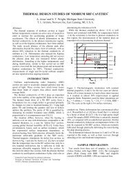
A description of <strong>the</strong> original controls <strong>system</strong> <strong>for</strong> <strong>the</strong>BCP <strong>system</strong> is covered in [10]. The modifications andimprovements to <strong>the</strong> original control <strong>system</strong> have beenimplemented and are presented in this paper.The BCP System <strong>for</strong> <strong>the</strong> ILC S0/S1 processing programwill be primarily used to remove <strong>the</strong> contaminants on <strong>the</strong>outside cavity surfaces to prevent fouling of <strong>the</strong> interiorsurfaces during <strong>the</strong> hydrogen degasification bake cycle.Until large grain and single-crystal cavity productionmatures, <strong>the</strong> relevancy of processing <strong>the</strong> inside surfaces offine-grain ILC cavities <strong>for</strong> vertical per<strong>for</strong>mance testing atvery high fields (>25MV/m) is limited due to <strong>the</strong> BCPquench field limit well below that of EP. However, BCPprocessing on large-grain and single crystal cavities hasshown great promise as a replacement <strong>for</strong> EP [11]. TheBCP System will play a significant role in provingwhe<strong>the</strong>r multi-cell large-grain or single crystal cavityprocessing can eliminate EP from <strong>the</strong> processing sequence.For <strong>the</strong> near future, <strong>the</strong> role of <strong>the</strong> BCP System will be toprovide external surface polishing of S0/S1 cavities andinternal polishing on o<strong>the</strong>r 1.3 GHz cavities not in <strong>the</strong>S0/S1 program.IndustrializationOne of <strong>the</strong> BCP System’s fundamental design preceptswas to build a tool with features attractive to industry.High volume cavity surface processing will need toolsthat are safe and easy to use with robust design whichallow quick change between operations. The BCP Systemdesign accomplished <strong>the</strong>se goals by focusing on operatortooling and controls <strong>system</strong>. These features are easilyduplicated in any BCP System constructed in <strong>the</strong> future.The BCP System design is modular in that many shapesand sizes of cavities can be processed without makingmodifications to <strong>the</strong> BCP System itself as long as <strong>the</strong>processed surfaces are within <strong>the</strong> capacity of <strong>the</strong> <strong>system</strong>.Each cavity type requires its own tooling (jackets, holdingfixtures, etc.), but <strong>the</strong> connections to <strong>the</strong> BCP System and<strong>the</strong> method in which <strong>the</strong> process takes place are <strong>the</strong> same.SafetyProcesses that use concentrated HF require extremeuser caution and tight procedure control. At ANL, a<strong>for</strong>mal safety program at <strong>the</strong> SCPF has been implementedthat dictates proper HF handling techniques, appropriatepersonal protective equipment, and emergency responseprocedures. Any operation utilizing HF or o<strong>the</strong>rconcentrated acids must obey <strong>the</strong> approved SCPFumbrella safety documents. In addition to <strong>the</strong> umbrellasafety documents, setup, operation, and shutdownprocedures are all controlled via checklist. This checklistensures all proper precautions specific to <strong>the</strong> proceduresare taken.The BCP System was designed to limit <strong>the</strong> BCP (HF)handling and contact opportunity to an absolute minimum.At no time does an operator physically manipulate <strong>the</strong>BCP o<strong>the</strong>r than when rolling BCP supply drums enclosedin secondary overpack containers. During routineoperation, <strong>the</strong> only opportunity <strong>for</strong> contact is duringfitting disconnection after a procedure. All fluid (BCP,Figure 2: BCP System flow schematic. Operator GUI screen capture.safety and implementing uncomplicated flow mechanics,cooling water, dilute waste) manipulation is per<strong>for</strong>med by
programmable logic controller (PLC) controlled flowmechanics. Should leaks in <strong>the</strong> plumbing occur, all likelyareas reside within secondary containment.Operator exposure to dilute waste is also extremelylimited. All dilute waste generated during a procedure isneutralized and pumped to a drain by an automatedneutralization <strong>system</strong>. Operator involvement in aprocedure is limited to connecting <strong>the</strong> cavity to <strong>the</strong> BCPSystem, stinging BCP drums, and running <strong>the</strong> procedureremotely from a control center located outside <strong>the</strong>chemistry room.Process ControlThe fluid flow mechanics are required to handle BCP,ultra pure water <strong>for</strong> rinsing and cooling, and dilute wastesimultaneously. Expecting an operator to manipulate<strong>the</strong>se fluids with numerous valve openings and closingsand pump activation and deactivation while monitoringseveral sensors is unreasonable in a process that issensitive to so many variables. There<strong>for</strong>e, a PLC andsoftware interface with a PC was chosen to per<strong>for</strong>m <strong>the</strong>seoperations. An operator is expected to key into <strong>the</strong>interface <strong>the</strong> procedure to be per<strong>for</strong>med, move <strong>the</strong>processes from one step to <strong>the</strong> next, and verify that <strong>the</strong>control <strong>system</strong> is responding to all sensors as needed.DESIGN DETAILSBCP and Neutralization SystemsThe fluid mechanics are divided into separatesub<strong>system</strong>s <strong>for</strong> BCP and cooling water flow. The BCPSystem flow schematic is shown in Figure 2 with <strong>the</strong>cooling water loop shown on <strong>the</strong> right and <strong>the</strong> BCP loopon <strong>the</strong> left. The separate loops do not share like plumbingwhich prevents inadvertent mixing of acid and water. Thesub<strong>system</strong>s meet at <strong>the</strong> cavity/jacket but are separated by<strong>the</strong> resonator wall. The cavity is enclosed in an etchingjacket and connected to five separate lines: BCP supplyand return, cooling water supply and return, and coolingwater overflow.The water cooling loop receives water from a gravityfeed tank which is automatically pre-filled be<strong>for</strong>e aprocedure begins. The cooling loop includes plumbingand pumps between a heat exchanger and <strong>the</strong> etchingjacket. The water flows on <strong>the</strong> opposite side of <strong>the</strong> etchprocess <strong>the</strong>reby removing <strong>the</strong> reaction heat. The reactionheat carried away by <strong>the</strong> water is removed from <strong>the</strong>cooling loop in a plate and frame heat exchanger. Anexternal chiller supplies <strong>the</strong> heat exchanger with 6C to10C chilled water. This double heat exchangearrangement prevents acid from escaping <strong>the</strong> chemistryroom to <strong>the</strong> primary chiller in <strong>the</strong> event of a leak between<strong>the</strong> etching jacket and cavity.BCP is supplied to <strong>the</strong> process via direct pumping froma pre-cooled drum. The BCP flows from <strong>the</strong> supply drumthrough <strong>the</strong> cavity and back to <strong>the</strong> drum. At <strong>the</strong>conclusion of <strong>the</strong> etching process, <strong>the</strong> BCP in <strong>the</strong> cavityand <strong>system</strong> plumbing flows into an acid dump tank whichresides below <strong>the</strong> process. The acid is immediatelypumped into <strong>the</strong> process supply drum. Once <strong>the</strong> cavity isfree of BCP, ultrapure water (UPW) from <strong>the</strong> gravity feedtank flushes through <strong>the</strong> <strong>system</strong> <strong>the</strong>reby rinsing <strong>the</strong> cavityand all lines that carry acid. The dilute waste generateddumps into a dilute waste tank next to <strong>the</strong> acid dump tank.The rinse cycles continue until <strong>the</strong> dilute waste reaches apH of 4 or higher as measured by a pH sensor located in<strong>the</strong> dilute waste tank. All of <strong>the</strong> dilute waste is pumpedfrom <strong>the</strong> tank to <strong>the</strong> automated neutralization <strong>system</strong>.The neutralization <strong>system</strong> contains a 95 gallon storagetank, 10 gpm recirculation pump, and metering pump thatdoses liquid NaOH into <strong>the</strong> tank. Redundant pH sensorsin line with <strong>the</strong> recirculation pump communicate with <strong>the</strong>PLC which ‘tells’ <strong>the</strong> metering pump to dose caustic into<strong>the</strong> tank until <strong>the</strong> pH of <strong>the</strong> dilute waste is above 5 – alevel safe to dump into <strong>the</strong> ANL sewage <strong>system</strong>. Noconcentrated acid is neutralized.All materials used to construct <strong>the</strong> BCP andneutralization <strong>system</strong>s are approved <strong>for</strong> HF handling.PVDF, Teflon, fluorinated Viton, and PFA are commonmaterials suitable <strong>for</strong> HF. Where possible, bead andcrevice free PVDF tube welding was employed tominimize <strong>the</strong> number of fittings. All valves and pumpsare certified <strong>for</strong> HF as well as o<strong>the</strong>r acids.The BCP System is shown in three photos in Figure 3as installed. The left photo is <strong>the</strong> neutralization <strong>system</strong>and its secondary containment. The center photo shows<strong>the</strong> BCP <strong>system</strong> and PVC test vessel. The right photoshows local ventilation hoods installed to capture processfumes released at <strong>the</strong> BCP supply drum that residesbeneath <strong>the</strong> hood openings.Figure 3: Neutralization <strong>system</strong>, BCP System, andventilation ductwork.Ventilation SystemRemoving process fumes (NO x , HF vapor) is critical tosafe operation. The ventilation <strong>system</strong> was designed tocapture fumes at <strong>the</strong> source, or potential source in <strong>the</strong> caseof leaks. All plumbing and vessels are located in a largeframe covered by a Lexan skin. The Lexan skin <strong>for</strong>ms afume hood with <strong>the</strong> draft created by a large suctionmanifold located at <strong>the</strong> top surface of <strong>the</strong> frame. TheBCP System plumbing was enclosed in a fume hood notto capture process fumes but to ga<strong>the</strong>r fumes frompossible leaks. Should a leak occur, an operator cansafely neutralize it without <strong>the</strong> risk of fume exposure.


![å¨åæãæç©ä¿æ¤ææå¦ãï¼å¤§äºï¼ââå åºææååºç¨.ppt [å
¼å®¹æ¨¡å¼]](https://img.yumpu.com/42555314/1/190x135/aaaeaaeccaaeaeaea-ai-1-4-aai-1-4-aaa-aaeaeaacppt-a-1-4-araea-1-4-.jpg?quality=85)