realisation of a prototype superconducting cw cavity ... - ResearchGate
realisation of a prototype superconducting cw cavity ... - ResearchGate
realisation of a prototype superconducting cw cavity ... - ResearchGate

Create successful ePaper yourself
Turn your PDF publications into a flip-book with our unique Google optimized e-Paper software.
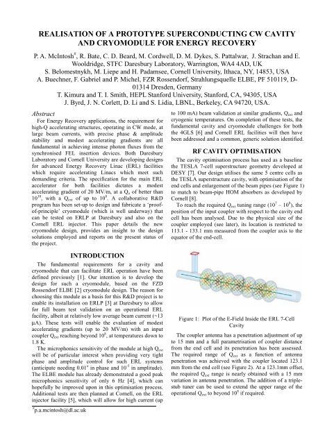
1.0E+091.0E+08Qext1.0E+07113.1 mm123.1 mm133.1 mmMinMax1.0E+06110 115 120 125 130 135Distance from End Cell (mm)Figure 2: Variation <strong>of</strong> Q ext with Antenna Extension andPositionFigure 4: ERLP LN2 Skeleton.INPUT COUPLERThe chosen solution for a suitable input coupler that iscapable <strong>of</strong> delivering 20 kW CW in standing wave, whilstalso providing adjustability in terms <strong>of</strong> its Q ext setting, isthe Cornell ERL injector coupler (see Figure 3) [9]. CPIhave successfully fabricated a number <strong>of</strong> these couplersand the power handling capability has been proven up to50 kW CW in travelling wave. Tests are continuing toprove stable operation in standing wave for the CornellERL injector <strong>prototype</strong> module.Original80K 300K2K 5KFigure 5: LN2 Skeleton Modifications.Modified80K InterceptremovedTable 1: Modified Cornell Coupler Heat LoadsParameter Original ModifiedMax Power (kW) 50 TW 20 SWAntenna Stroke (mm) >15
Cross piecescamsuprightsPiezo cartridgeMotor/gearboxFigure 6: Adaptation <strong>of</strong> the Saclay II Tuner to the 7-cellCavityHOM ABSORBER INTEGRATIONIn its original configuration, the ELBE cryomoduledoes not have provision for the support <strong>of</strong> large beampipe HOM absorbers, either between the two cavities or atits ends. Both the HOM absorbers and the Cornell inputcouplers require an additional 5 K thermal interceptwhich also complicates the support implementation interms <strong>of</strong> its thermal isolation.Figure 8: End HOM Absorber Ring and Rod SupportCRYOMODULE MODIFICATIONSStanford University have provided a spare SCAcryomodule vessel, to be used as a basis for the modified<strong>cavity</strong> string. The size <strong>of</strong> this vessel is identical to that <strong>of</strong>the ACCEL fabricated ERLP modules [12], which isbased on the FZD Rossendorf ELBE module (see Figure9). The process <strong>of</strong> performing configurational changesand including new components to an existing cryomoduledesign, requires careful tracking <strong>of</strong> all interfaces that maybe affected.Figure 7: Central HOM Absorber Cage and Rod SupportThe approach chosen is to incorporate a rigid supportcage between the two cavities, which locks thelongitudinal movement <strong>of</strong> both input couplers duringcooldown. The HOM absorber, with its 5 K and 80 Kcooling circuits is then thermally isolated from the cagedsupport frame via thin (3mm diameter) titanium supportrods, which are arranged to ensure precise longitudinaland transverse positioning and support (see Figure 7). Thesame rod support scheme has been adopted for each <strong>of</strong> thetwo end HOM absorbers with the support frame similarlyattached directly to the 2 K <strong>cavity</strong> helium can (see Figure8).Figure 9: ERLP and ELBE ModuleUtilisation <strong>of</strong> the FZD Rossendorf 3D assemblydrawings has assisted this process tremendously to ensurethat new fabrication drawings are not only accurate, butthat the various inter-module dependencies are validated.The fundamental cryomodule changes required to beaccommodated are:• Replacement <strong>of</strong> the 2 existing TESLA 9-cell cavitieswith modified TESLA 7-cell superstructure cavities.• Use <strong>of</strong> high CW power (>20 kW) input couplers.• Use <strong>of</strong> beam-pipe HOM absorbers.• Replacement <strong>of</strong> the existing tuner with one thatincorporates piezo actuators for fast feedback.• Provision for an additional 5 K cooling circuit forcooling the coupler and HOM absorbers.
Wherever possible we have tried to maintain the samemounting and location points for the <strong>cavity</strong> string withinthe original module to minimise additional R&D andfabrication costs. Retaining also as much <strong>of</strong> the originalcryogenic cooling circuits is hoped to sustain thismodules’ quiet microphonics susceptibility. Figure 10shows the modified module layout which now includesthe 7-cell cavities, beam-pipe HOM absorbers, modifiedCornell input couplers and Saclay II tuners.Figure 10: Modified Module LayoutSTATUS AND SCHEDULEThe cryomodule project is currently on track to have allcomponents delivered on site by mid July 2008, includingfabrication <strong>of</strong> all crymodule sub-components. Anadditional 5 months is then scheduled to complete the<strong>cavity</strong> string assembly and module integration atDaresbury, ready for installation on ERLP in early 2009.The Cornell HOM absorbers are expected to bedelivered from ACCEL by end 2007. The modifiedCornell RF couplers are on order with CPI and delivery isexpected in March 2008. The modified Saclay II typetuner is fully detailed, with long-lead items already onorder. RF simulations <strong>of</strong> the <strong>cavity</strong> shape are complete,and drawings <strong>of</strong> the required <strong>cavity</strong> shapes and heliumtank are in progress. Milestone dates for this R&D projectinclude:• ACCEL HOM absorbers delivered Dec 2007• Module internal drawings complete Dec 2007• Saclay tuners delivered Feb 2008• Module centre section modified Feb 2008• CPI Couplers delivered Mar 2008• Tooling and fixtures fabricated Mar 2008• All module components available Jul 2008• Module assembled Dec 2008• Installation on ERLP Early 2009• Installation on Cornell ERL Injector Early 2010CONCLUSIONSThis cryomodule R&D project has benefited greatlyfrom the strong interaction between all collaborators. Thevast amount <strong>of</strong> R&D that has been performed over recentyears as part <strong>of</strong> the TESLA Technology Collaboration(TTC) has enabled the rapid <strong>realisation</strong> <strong>of</strong> such acryomodule, which is capable <strong>of</strong> high gradient and highpower CW operation, with the ability to compensate forexcessive microphonics to very tight phase and amplitudetolerances via its integrated fast piezo tuning. Buildingalso on the experience gained at HEPL, FZD Rossendorfand more recently ERLP, the baseline 2-<strong>cavity</strong>cryomodule being employed for this R&D project showsgreat promise in terms <strong>of</strong> being able to achieve thechallenging requirements for ERL operation. The R&Dperformed at Cornell for their ERL injector module hasenabled proven components to be employed, therebyminimising the technical risks for this project.The utilisation <strong>of</strong> a cryomodule that already possesseslow microphonics susceptibility is hoped to be improvedupon in the final design to maximise its efficiency whenoperated as an ERL module. The project is on track toenable low average beam current validation tests to beperformed on ERLP in 2009, complimented by highcurrent tests on Cornell’s ERL injector <strong>prototype</strong> in 2010.REFERENCES[1] P.A. McIntosh et al, “Development <strong>of</strong> a PrototypeSuperconducting CW Cavity and Cryomodule forEnergy Recovery”, EPAC’06, Edinburgh, June 2006,pp. 436 – 438.[2] “The ELBE Radiation Source Project”, Acta PhysicaPolonica B, No. 5, Vol. 30 (1999), pp. 1639 - 1645.[3] M.W. Poole et al, “4GLS and the Energy RecoveryLinac Prototype Project at Daresbury Laboratory”,PAC’05, Knoxville, USA, 2005, pp. 431-433.[4] J. Knobloch, “Limits on the Bandwidth for SRFCavities for ERL linacs”, FLS2006, DESY, May2006, WG223.[5] M. Tigner et al, “Phase 1 Energy Recovery Linac atCornell University”, EPAC02, Paris, pp 644 - 646.[6] M.W. Poole et al, “4GLS - a New Type <strong>of</strong> FourthGeneration Light Source Facility”, PAC’03, Portland,May 2003, pp. 183 – 185.[7] J. Sekutowicz et al, “Superconducting Superstructurefor the TESLA Collider”, EPAC98, Stockholm, 1998,pp.1876-1878.[8] V. Shemelin et al, "Status <strong>of</strong> HOM Load for theCornell ERL Injector", EPAC’06, Edinburgh, June2006, pp. 478 – 480.[9] V. Veshcherevich, “Input Coupler for ERL InjectorCavities”, PAC’03, Portland, USA, May 2003, pp.1201 – 1203.[10] G Devanz et al, “Compensation <strong>of</strong> Lorenz ForceDetuning <strong>of</strong> a TTF 9-cell Cavity with a NewIntegrated Piezo Tuner”, EPAC’06, Edinburgh, June2006, pp. 378 – 380.[11] O. Kugeler, “Measurement and Compensation <strong>of</strong>Microphonics in CW Operated TESLA-type Cavities,ERL’07, Daresbury Laboratory, UK, May 2007.[12] M. Pekeler et al, “Industrial Production <strong>of</strong>Superconducting 1.3 GHz Accelerator Modules andComponents for FEL Application”, FEL’04, Trieste,2004, pp. 379 – 380.

![å¨åæãæç©ä¿æ¤ææå¦ãï¼å¤§äºï¼ââå åºææååºç¨.ppt [å
¼å®¹æ¨¡å¼]](https://img.yumpu.com/42555314/1/190x135/aaaeaaeccaaeaeaea-ai-1-4-aai-1-4-aaa-aaeaeaacppt-a-1-4-araea-1-4-.jpg?quality=85)