realisation of a prototype superconducting cw cavity ... - ResearchGate
realisation of a prototype superconducting cw cavity ... - ResearchGate
realisation of a prototype superconducting cw cavity ... - ResearchGate

You also want an ePaper? Increase the reach of your titles
YUMPU automatically turns print PDFs into web optimized ePapers that Google loves.
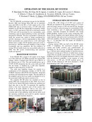
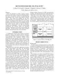
Wherever possible we have tried to maintain the samemounting and location points for the <strong>cavity</strong> string withinthe original module to minimise additional R&D andfabrication costs. Retaining also as much <strong>of</strong> the originalcryogenic cooling circuits is hoped to sustain thismodules’ quiet microphonics susceptibility. Figure 10shows the modified module layout which now includesthe 7-cell cavities, beam-pipe HOM absorbers, modifiedCornell input couplers and Saclay II tuners.Figure 10: Modified Module LayoutSTATUS AND SCHEDULEThe cryomodule project is currently on track to have allcomponents delivered on site by mid July 2008, includingfabrication <strong>of</strong> all crymodule sub-components. Anadditional 5 months is then scheduled to complete the<strong>cavity</strong> string assembly and module integration atDaresbury, ready for installation on ERLP in early 2009.The Cornell HOM absorbers are expected to bedelivered from ACCEL by end 2007. The modifiedCornell RF couplers are on order with CPI and delivery isexpected in March 2008. The modified Saclay II typetuner is fully detailed, with long-lead items already onorder. RF simulations <strong>of</strong> the <strong>cavity</strong> shape are complete,and drawings <strong>of</strong> the required <strong>cavity</strong> shapes and heliumtank are in progress. Milestone dates for this R&D projectinclude:• ACCEL HOM absorbers delivered Dec 2007• Module internal drawings complete Dec 2007• Saclay tuners delivered Feb 2008• Module centre section modified Feb 2008• CPI Couplers delivered Mar 2008• Tooling and fixtures fabricated Mar 2008• All module components available Jul 2008• Module assembled Dec 2008• Installation on ERLP Early 2009• Installation on Cornell ERL Injector Early 2010CONCLUSIONSThis cryomodule R&D project has benefited greatlyfrom the strong interaction between all collaborators. Thevast amount <strong>of</strong> R&D that has been performed over recentyears as part <strong>of</strong> the TESLA Technology Collaboration(TTC) has enabled the rapid <strong>realisation</strong> <strong>of</strong> such acryomodule, which is capable <strong>of</strong> high gradient and highpower CW operation, with the ability to compensate forexcessive microphonics to very tight phase and amplitudetolerances via its integrated fast piezo tuning. Buildingalso on the experience gained at HEPL, FZD Rossendorfand more recently ERLP, the baseline 2-<strong>cavity</strong>cryomodule being employed for this R&D project showsgreat promise in terms <strong>of</strong> being able to achieve thechallenging requirements for ERL operation. The R&Dperformed at Cornell for their ERL injector module hasenabled proven components to be employed, therebyminimising the technical risks for this project.The utilisation <strong>of</strong> a cryomodule that already possesseslow microphonics susceptibility is hoped to be improvedupon in the final design to maximise its efficiency whenoperated as an ERL module. The project is on track toenable low average beam current validation tests to beperformed on ERLP in 2009, complimented by highcurrent tests on Cornell’s ERL injector <strong>prototype</strong> in 2010.REFERENCES[1] P.A. McIntosh et al, “Development <strong>of</strong> a PrototypeSuperconducting CW Cavity and Cryomodule forEnergy Recovery”, EPAC’06, Edinburgh, June 2006,pp. 436 – 438.[2] “The ELBE Radiation Source Project”, Acta PhysicaPolonica B, No. 5, Vol. 30 (1999), pp. 1639 - 1645.[3] M.W. Poole et al, “4GLS and the Energy RecoveryLinac Prototype Project at Daresbury Laboratory”,PAC’05, Knoxville, USA, 2005, pp. 431-433.[4] J. Knobloch, “Limits on the Bandwidth for SRFCavities for ERL linacs”, FLS2006, DESY, May2006, WG223.[5] M. Tigner et al, “Phase 1 Energy Recovery Linac atCornell University”, EPAC02, Paris, pp 644 - 646.[6] M.W. Poole et al, “4GLS - a New Type <strong>of</strong> FourthGeneration Light Source Facility”, PAC’03, Portland,May 2003, pp. 183 – 185.[7] J. Sekutowicz et al, “Superconducting Superstructurefor the TESLA Collider”, EPAC98, Stockholm, 1998,pp.1876-1878.[8] V. Shemelin et al, "Status <strong>of</strong> HOM Load for theCornell ERL Injector", EPAC’06, Edinburgh, June2006, pp. 478 – 480.[9] V. Veshcherevich, “Input Coupler for ERL InjectorCavities”, PAC’03, Portland, USA, May 2003, pp.1201 – 1203.[10] G Devanz et al, “Compensation <strong>of</strong> Lorenz ForceDetuning <strong>of</strong> a TTF 9-cell Cavity with a NewIntegrated Piezo Tuner”, EPAC’06, Edinburgh, June2006, pp. 378 – 380.[11] O. Kugeler, “Measurement and Compensation <strong>of</strong>Microphonics in CW Operated TESLA-type Cavities,ERL’07, Daresbury Laboratory, UK, May 2007.[12] M. Pekeler et al, “Industrial Production <strong>of</strong>Superconducting 1.3 GHz Accelerator Modules andComponents for FEL Application”, FEL’04, Trieste,2004, pp. 379 – 380.

![å¨åæãæç©ä¿æ¤ææå¦ãï¼å¤§äºï¼ââå åºææååºç¨.ppt [å
¼å®¹æ¨¡å¼]](https://img.yumpu.com/42555314/1/190x135/aaaeaaeccaaeaeaea-ai-1-4-aai-1-4-aaa-aaeaeaacppt-a-1-4-araea-1-4-.jpg?quality=85)