Download paper - Department of Materials Science and Metallurgy ...
Download paper - Department of Materials Science and Metallurgy ...
Download paper - Department of Materials Science and Metallurgy ...

You also want an ePaper? Increase the reach of your titles
YUMPU automatically turns print PDFs into web optimized ePapers that Google loves.
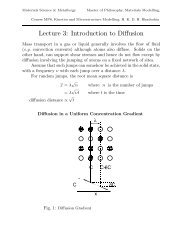
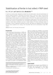
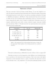
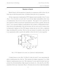
for X–ray characterisation by dissolving the ferrite using nital, with the residue filtered through a0.1 µm poresizecellulosenitratemembrane;inthiscasethescanstep size was 0.02 ◦ .TheVickershardness values reported represent an average <strong>of</strong> five measurements conducted using a 50 kg load.3. Phase diagram <strong>and</strong> heating experimentsThe original choice <strong>of</strong> tempering temperatures was based on phase diagram calculations usingMTDATA [33] <strong>and</strong> the SGTE plus database [34], allowing cementite, M 23 C 6 , M 6 C, M 7 C 3 , MC,ferrite <strong>and</strong> austenite to exist as possible phases (the ‘M’ st<strong>and</strong>sformetalatoms). Use<strong>of</strong>theTCFE database made no significant difference to the outcome. As canbeseenfromFig.2a,theformation <strong>of</strong> austenite under equilibrium conditions should beginatabout795 ◦ C<strong>and</strong>becompletedat 915 ◦ C, so the highest tempering temperature was selected to be about 750 ◦ C. However, whenexperiments were conducted, the austenite formation temperature was found to be much lower thanthat predicted by the phase diagram calculation. These experiments will be reported later, butdilatometry confirmed that the calculations in fact overestimate the Ae 1 temperature beyond whichaustenite formation becomes thermodynamically possible, with the Ac 1 temperature in practicebeing lower by at least 50 ◦ C, Fig. 2b.4. HardnessEvery single value <strong>of</strong> recorded hardness is plotted in Fig. 3 in ordertoillustratethescatterinindividualsamples. It is expected from elementary kinetic theory that the hardness during temperingshould vary approximately linearly with the logarithm <strong>of</strong> time [35], as confirmed by experimentalinvestigations on the tempering <strong>of</strong> martensitic steels in the absence<strong>of</strong>secondaryhardening[36–38].It is common in tempering studies to use a tempering parameter torationalisetheeffects<strong>of</strong>time<strong>and</strong> temperature [35, 39, 40]; this also includes a logarithmic dependence on time. The parameteris defined as T (20+log t) whereT is expressed in Kelvin <strong>and</strong> t in hours. The normalised hardness isgiven by (H −H min )/(H max −H min ), where H, H max <strong>and</strong> H min represent the hardness, untemperedhardness <strong>and</strong> fully–s<strong>of</strong>tened hardness respectively. Although commonly applied to martensiticsteels, it has been used for precisely the type <strong>of</strong> bainite considered here, albeit for a steel <strong>of</strong> adifferent chemical composition [25]. Figure 3b compares the data from the present work withthe curve from the previous work [25] which was designed to look at the stability <strong>of</strong> the retainedaustenite. All the new data fall close to the original curve with the exception <strong>of</strong> the values fromthe 753 ◦ Ctemperingexperiments,whereonlytheshortheat–treatment time data approach thegeneral trend. This anomalous behaviour will be discussed later in the context <strong>of</strong> metallographicobservations.3
While metallography has been conducted on tempering at all the temperatures studied, we presentfurther results only from the treatment at 708 ◦ Cinordertodemonstratethatthetemperatureisbelow Ae 1 so that austenite formation is completely avoided. Figure 7 shows that the microstructureis very resistant to tempering, but the absence <strong>of</strong> austenite, <strong>and</strong>hence<strong>of</strong>martensite,leadstoamuch lower hardness as shown in Fig. 3a than following heat treatment at 753 ◦ C.It is generally considered that a hardness <strong>of</strong> 230 HV or less is appropriate for the fabrication<strong>and</strong> easy–machining <strong>of</strong> steel for complex components such as bearings [22, 41]. The 708 ◦ Cheattreatment, for 42 days, does not achieve this, <strong>and</strong> the time period required is simply too long inany case. Speroidisation from a martensitic condition which beginswithfinecarbidesalsotakestoo long to achieve such a low hardness in a high–carbon steel. As a consequence, a method wasdeveloped some time ago [42–44], involving the transformation <strong>of</strong> austenite into divorced pearlite,illustrated schematically in Fig. 8. Proeuctectoid particles present in the austenite simply absorbthe excess carbon that is partitioned into the austenite as ferrite forms on cooling, thus leading tocoarse cementite particles in a matrix <strong>of</strong> ferrite, i.e., a spheroidised structure by continuous cooling.This process is used routinely with the high–carbon steels for bearings [22]. Unfortunately, thisparticular procedure is not feasible for the present alloy because as shown in Fig. 2a, the alloybecomes essentially fully austenitic once the ferrite disappears, whereas a divorced eutectoid requiresthe existence <strong>of</strong> particles <strong>of</strong> cementite within an otherwise austenitic phase.Aheattreatmentwasattemptedwiththeaim<strong>of</strong>makingthematerial fully austenitic, then coolingto allow proeutectoid cementite, <strong>and</strong> then hoping for a divorced eutectoid transformation. Theprecise form is as used in the bearing steel industry [22, 45], butbeginningwiththelow–temperaturebainite with a hardness <strong>of</strong> 660 ± 4HV :800 ◦ C, 1 h → cool to 750 ◦ Cat25Kh −1 → cool to 690 K at 10 K h −1 ,→ cool to room temperature at 360 K h −1 .This led to a mixed microstructure <strong>of</strong> lamellar <strong>and</strong> divorced pearlite structure with a hardness <strong>of</strong>301 ± 4HV,presumablybecauseassuggestedbytheory[45],anappropriate dispersion <strong>of</strong> cementiteparticles is required in order to induce a fully divorced pearlite, Fig. 9a. It is also interesting tonote that cooling to 750 ◦ Cdidnotcauseferriteformationbecausethekinetics<strong>of</strong>thisreactionareextremely slow in alloys <strong>of</strong> this class, due to their high hardenability [46].The presence <strong>of</strong> ferrite may help s<strong>of</strong>ten the material, <strong>and</strong> as shown previously, coarse ferrite can beintroduced into the microstructure by heat treatment at 753 ◦ C, with the aim <strong>of</strong> transforming anyaustenite that forms into pearlite rather than martensite. This was achieved by holding the initialmixture <strong>of</strong> bainitic ferrite <strong>and</strong> retained austenite, at 753 ◦ Cfor13h,thencoolingrapidlyto650 ◦ Cto transform any austenite into pearlite. The hardness <strong>of</strong> this structure (Fig. 9b) was found to be552 ± 3HV.On the other h<strong>and</strong>, it is clearly possible to obtain a structure inwhichα, γ <strong>and</strong> θ co–exist, withcementite particles present in both <strong>of</strong> the major phases.5
6. Conclusions1. It has been difficult to achieve sufficient s<strong>of</strong>tening in a structure which is initially a fine mixture<strong>of</strong> platelets <strong>of</strong> bainitic ferrite separated by films <strong>of</strong> carbon–enriched retained austenite exceptby using impractically long heat–treatments. The decomposition <strong>of</strong> films <strong>of</strong> austenite leadsto arrays <strong>of</strong> carbides at the ferrite plate boundaries, preventing them from coarsening.2. Tempering treatments are limited to below about 750 ◦ Cinordertoavoidtheformation<strong>of</strong>austenite.3. Continuous cooling spheroidisation treatments <strong>of</strong> the kind exploited in the bearings industryare also ineffective due to the absence <strong>of</strong> the proeutectoid cementite particles needed to formdivorced pearlite.4. The carbon concentration <strong>of</strong> the steel should be increased to permit a dispersion <strong>of</strong> cementiteparticles within the austenite at the austenitisation temperature. These particles should thensimply grow to absorb any carbon that is partitioned by ferrite as the steel is cooled throughthe eutectoid temperature, thereby promoting a spheroidised microstructure.The authors are grateful to British Universities Iraq Consortium <strong>and</strong> the Council for AssistingRefugee Academics (CARA) for funding this work, to the Ministry <strong>of</strong> Education & Scientific Researchin Iraq, <strong>and</strong> to the University <strong>of</strong> Cambridge for the provision <strong>of</strong> laboratory facilities.6
Figure 1: The initial nanostructureobtained following transformationat 200 ◦ Cfor3days,consisting<strong>of</strong> platelets <strong>of</strong> ferrite (light)separated by films <strong>of</strong> austenite.The mean free slip distance in suchastructureistwicethetruethickness<strong>of</strong> the plates. Much moremetallographic information includingquantitative measurements hasbeen reviewed in [31], which containsmany original references.(a)(b)Figure 2: (a) Calculated equilibrium phase fractions <strong>of</strong> ferrite (α), austenite (γ), cementite (θ) <strong>and</strong>M 23 C 6 ,asafunction<strong>of</strong>temperature.(b)Dilatometricstrainrecorded during heating at 30 K s −1 .7
(a)(b)(c)(d)Figure 4: Samples tempered at 753 ◦ Cforavariety<strong>of</strong>timeperiods. Thesymbolsα, α ′ , θ <strong>and</strong>Pst<strong>and</strong>forferrite,martensite,cementite<strong>and</strong>pearliterespectively. (a) After 30 min, showing theprecipitation <strong>of</strong> carbides. (b) After 12 h, with austenite (now α ′ )formation<strong>and</strong>dissolution<strong>of</strong>somecarbides. (c) After 20 days <strong>of</strong> tempering. (d) After 42 days <strong>of</strong> tempering.9
Figure 5: Sample heat–treated at 753 ◦ Cfor42days. (a)X–raydiffractionpattern,showingthepresence <strong>of</strong> a discernible amount <strong>of</strong> retained austenite. (b) X–ray diffraction from extracted residue.All the peaks can be attributed to cementite, with the exception <strong>of</strong> the unidentified peak at theposition <strong>of</strong> the arrow.10
Figure 6: Sample heat–treated at 753 ◦ Cfor42days. TheCr/Feratiosmarked1,2,3,4haveerrors <strong>of</strong> ± 0.03, 0.2, 0.2 <strong>and</strong> 0.03 respectively. (a,b) Showing the genesis <strong>of</strong> pearlite at particles <strong>of</strong>cementite which are in contact with both ferrite <strong>and</strong> austenite. (c) The arrows show minute colonies<strong>of</strong> pearlite at γ–α–θ interfaces, but not at the numerous cementite particles trapped within theaustenite.11
(a)(b)(c)(d)Figure 7: Samples tempered at 708 ◦ Cforavariety<strong>of</strong>timeperiods. (a)After1day,(b)4days,(c) 8 days <strong>and</strong> (d) 42 days at the tempering temperature.Figure 8: The mechanism <strong>of</strong> the divorced eutectoid transformation<strong>of</strong> a mixture <strong>of</strong> austenite <strong>and</strong> fine cementite12
(a)(b)Figure 9: (a) Mixed microstructure <strong>of</strong> divorced (arrowed) <strong>and</strong> lamellarpearlitegeneratedbyacomplex continuous cooling heat treatment <strong>of</strong> the type used for bearing steels. (b) Pearlite generatedduring isothermal transformation at 650 ◦ Cinapartiallyausteniticsampleobtainedbyheattreatment at 753 ◦ C.13
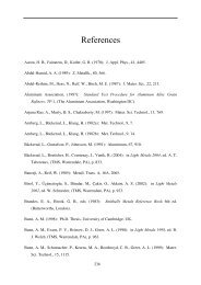
References[1] F. G. Caballero, H. K. D. H. Bhadeshia, K. J. A. Mawella, D. G. Jones, P. Brown: Mater. Sci.Tech. – Lond. 18 (2002) 279–284.[2] C. G. Mateo, H. K. D. H. Bhadeshia: Mater. Sci. Eng. A – Struct. 378A (2004) 289–292.[3] P. M. Brown, D. P. Baxter: Hyper–strength bainitic steels: in: <strong>Materials</strong> <strong>Science</strong> <strong>and</strong> Technology2004: TMS, Warrendale, Pennsylvania, USA, 2004: pp. 433–438.[4] S. J. Paynter: B.Sc. thesis, effects on the hardness <strong>of</strong> superbainite through isothermal heat–treatment (2006).[5] H. K. D. H. Bhadeshia, A. R. Waugh: Acta Metall. 30 (1982) 775–784.[6] M. Peet, S. S. Babu, M. K. Miller, H. K. D. H. Bhadeshia: Scr. Mater.50(2004)1277–1281.[7] F. G. Caballero, M. K. Miller, S. S. Babu, C. Garcia-Mateo: ActaMater.55(2007)381–390.[8] C. Garcia-Mateo, F. G. Caballero: Mater. Trans. 46 (2005) 1839–1846.[9] H. K. D. H. Bhadeshia: Mater. Sci. Eng. A – Struct. 481–482 (2008) 36–39.[10] H. K. D. H. Bhadeshia: Mater. Sci. Tech. – Lond. 21 (2005) 1293–1302.[11] P. Zhang, F. C. Zhang, Z. G. Yan, T. S. Wang, L. H. Qian: Mater. Sci. Forum 675–677 (2011)585–588.[12] T. S. Wang, J. Yang, C. J. Shang, X. Y. Li, B. Lv, M. Zhang, F. C.Zhang:Surf.Coat.Tech.202 (2008) 4036–4040.[13] F. C. Zhang, T. S. Wang, P. Zhang, C. L. Zhang, B. Lv, M. Zhang, Y. Z. Zhang: Scr. Mater.59 (2008) 294–296.[14] P. Zhang, F. C. Zhang, Z. G. Yan, T. S. Wang, L. H. Qian: Wear 271(2011)697–704.[15] P. Zhang, F. C. Zhang, T. S. Wang: Appl. Surf. Sci. 257 (2011) 7609–7614.[16] M. J. Peet, P. Hill, M. Rawson, S. Wood, H. K. D. H. Bhadeshia: Mater. Sci. Tech. – Lond.27 (2011) 119–123.[17] S. Khare, K. Y. Lee, H. K. D. H. Bhadeshia: Metall. Mater. Trans. A 41A (2010) 922–928.[18] C. Menapace, I. Lonardelli, M. Tait, A. Moinari: Mater. Sci. Eng. A – Struct. 517 (2009) 1–7.[19] J. A. da Cruz, T. F. M. Rodrigues, V. D. C. Viana, D. B. Santos: Mater. Sci. Forum 706–709(2012) 173–180.[20] F. G. Caballero, H. K. D. H. Bhadeshia: Curr. Opin. Sol. St. M. 8 (2004) 251–257.[21] C. Garcia-Mateo, F. G. Caballero, H. K. D. H. Bhadeshia: ISIJ Int.l 43 (2003) 1238–1243.[22] H. K. D. H. Bhadeshia: Prog. Mater. Sci. 57 (2012) 268–435.14
[23] K. J. Irvine, F. B. Pickering, W. C. Heselwood: J. Iron Steel I. 186 (1957) 54–67.[24] K. J. Irvine, F. B. Pickering, W. C. Heselwood, M. Atkins: J.IronSteelI.186(1957)54–67.[25] C. Garcia-Mateo, M. Peet, F. G. Caballero, H. K. D. H. Bhadeshia: Mater. Sci. Tech. – Lond.20 (2004) 814–818.[26] F. G. Caballero, H. K. D. H. Bhadeshia, K. J. A. Mawella, D. G.Jones,P.Brown:Mater.Sci.Tech. – Lond. 17 (2001) 512–516.[27] F. G. Caballero, H. K. D. H. Bhadeshia, K. J. A. Mawella, D. G.Jones,P.Brown:Mater.Sci.Tech. – Lond. 17 (2001) 517–522.[28] E. Houdremont, H. Schrader: Arch. Eisen. 10 (1932) 523A–534A.[29] C. Garcia-Mateo, F. G. Caballero, H. K. D. H. Bhadeshia: ISIJ Inter. 43 (2003) 1821–1825.[30] H. I. Aaronson, H. A. Domian, G. M. Pound: TMS–AIME 236 (1966) 781–796.[31] H. K. D. H. Bhadeshia: Proc. Roy. Soc. A – Math. Phys. 466 (2010) 3–18.[32] S. Kundu, K. Hase, H. K. D. H. Bhadeshia: Proc. Roy. Soc. A –Math.Phys.463(2007)2309–2328.[33] NPL: MTDATA: S<strong>of</strong>tware, National Physical Laboratory, Teddington, U.K. (2006).[34] K. Hack (Ed.): The SGTE Casebook: Thermodynamics at work: The Institute <strong>of</strong> <strong>Materials</strong>,London, 1996.[35] J. H. Hollomon, L. D. Jaffe: Trans. Met. Soc. AIME 162 (1945) 223–249.[36] E. D. Hyam, J. Nutting: J Iron Steel I. 184 (1956) 148–165.[37] G. R. Speich: Trans. Met. Soc. AIME 245 (1969) 2553–2564.[38] G. R. Speich, W. C. Leslie: Metall. Trans. 3 (1972) 1043–1054.[39] F. R. Larson, J. Miller: Trans. ASME 74 (1952) 765–781.[40] R. A. Grange, C. R. Hribal, L. F. Porter: Metall. Trans. A 8A (1977) 1775–1785.[41] W. Li, Y. Wang, X. Z. Yang: Trib. Lett. 18 (2005) 353–357.[42] J. H. Whitley: J. Iron <strong>and</strong> Steel I. 105 (1922) 339–357.[43] S. L. Gertsman: Research <strong>and</strong> special projects report for 1965: Tech.rep.:Canadian<strong>Department</strong><strong>of</strong> Mines <strong>and</strong> Technical Surveys: Otawa, Canada (1966).[44] J. D. Verhoeven, E. D. Gibson: Metall. Mater. Trans. A 29 (1998) 1181–1189.[45] J. D. Verhoeven: Metall. Mater. Trans. A 31 (2000) 2431–2438.[46] C. Garcia-Mateo, F. G. Caballero, H. K. D. H. Bhadeshia: J. Phys. Colloque 112 (2003)285–288.15