Stabilisation of ferrite in hot rolled d-TRIP steel - Computational ...
Stabilisation of ferrite in hot rolled d-TRIP steel - Computational ...
Stabilisation of ferrite in hot rolled d-TRIP steel - Computational ...

Create successful ePaper yourself
Turn your PDF publications into a flip-book with our unique Google optimized e-Paper software.
<strong>Stabilisation</strong> <strong>of</strong> <strong>ferrite</strong> <strong>in</strong> <strong>hot</strong> <strong>rolled</strong> d-<strong>TRIP</strong> <strong>steel</strong>H. L. Yi 1 , K. Y. Lee 2 and H. K. D. H. Bhadeshia* 1,3A <strong>steel</strong> has recently been designed to benefit from the deformation <strong>in</strong>duced transformation <strong>of</strong>reta<strong>in</strong>ed austenite present <strong>in</strong> association with ba<strong>in</strong>itic <strong>ferrite</strong>. It has as its major microstructuralcomponent, dendrites <strong>of</strong> d-<strong>ferrite</strong> <strong>in</strong>troduced dur<strong>in</strong>g solidification. The d-<strong>ferrite</strong> replaces theallotriomorphic <strong>ferrite</strong> present <strong>in</strong> conventional alloys <strong>of</strong> this k<strong>in</strong>d. The authors exam<strong>in</strong>e here thestability <strong>of</strong> this d-<strong>ferrite</strong> dur<strong>in</strong>g heat<strong>in</strong>g <strong>in</strong>to a temperature range typical <strong>of</strong> <strong>hot</strong> roll<strong>in</strong>g conditions. Itis found that contrary to expectations from calculated phase diagrams, the <strong>steel</strong> becomes fullyaustenitic under these conditions and that a better balance <strong>of</strong> <strong>ferrite</strong> promot<strong>in</strong>g solutes isnecessary <strong>in</strong> order to stabilise the dendritic structure. New alloys are designed for this purposeand are found suitable for <strong>hot</strong> roll<strong>in</strong>g <strong>in</strong> the two-phase field over the temperature range 900–1200uC.Keywords: <strong>TRIP</strong> <strong>steel</strong>, d-<strong>ferrite</strong>, Alloy design, Phase transformationIntroductionA delta transformation <strong>in</strong>duced plasticity (d-<strong>TRIP</strong>) <strong>steel</strong>has an unconventional microstructure <strong>in</strong> which themajor constituent is d-<strong>ferrite</strong>, which forms dur<strong>in</strong>gsolidification and is permanently reta<strong>in</strong>ed after solidification.1 The rest <strong>of</strong> the structure can be transformed<strong>in</strong>to a mixture <strong>of</strong> ba<strong>in</strong>itic <strong>ferrite</strong> and austenite, which isstabilised by the partition<strong>in</strong>g <strong>of</strong> carbon between thesetwo allotropic forms <strong>of</strong> iron. It is this austenite, whichbehaves as <strong>in</strong> conventional <strong>TRIP</strong> assisted <strong>steel</strong>s, 2–9 andundergoes deformation <strong>in</strong>duced transformation to martensiteand, as a result, enhances the ductility <strong>of</strong> thealloy. Hence, the acronym <strong>TRIP</strong>, which stands fortransformation–<strong>in</strong>duced plasticity. 10 The <strong>steel</strong> has <strong>in</strong>terest<strong>in</strong>gproperties <strong>in</strong> its as cast state: an ultimate tensilestrength <strong>of</strong> y1000 MPa and a total elongation, almostall <strong>of</strong> which is uniform, <strong>of</strong> 23%.There is a difficulty with the alloy design. In spite <strong>of</strong>cool<strong>in</strong>g rates as slow as y20 K s 21 , solid statetransformation after solidification is completed exhibitslarge deviations from equilibrium conditions. 1Compositions which should, accord<strong>in</strong>g to phase diagramcalculations, show large quantities <strong>of</strong> d-<strong>ferrite</strong>dendrites, <strong>of</strong>ten display zero or much reduced fractionson cast<strong>in</strong>g. This is because the austenite that formsdur<strong>in</strong>g cool<strong>in</strong>g by the solid state transformation <strong>of</strong> coredd-dendrites does so without the required partition<strong>in</strong>g <strong>of</strong>substitutional solutes, particularly alum<strong>in</strong>ium.It is important <strong>in</strong> the d-<strong>TRIP</strong> concept to ma<strong>in</strong>ta<strong>in</strong>, asfar as is possible, the <strong>ferrite</strong> produced dur<strong>in</strong>g solidificationbecause its presence at all temperatures should1 Graduate Institute <strong>of</strong> Ferrous Technology (GIFT), Pohang University <strong>of</strong>Science and Technology (POSTECH), Pohang 790-784, Korea2 POSCO Technical Research Laboratories, Gwangyang-si, Jeonnam,Korea3 Department <strong>of</strong> Materials Science and Metallurgy, University <strong>of</strong>Cambridge, Cambridge CB2 3QZ, UK*Correspond<strong>in</strong>g author, email hkdb@cam.ac.ukimprove its resistance spot weldability. If the materialfails to become fully austenitic <strong>in</strong> the heat affected zone(HAZ), then it also becomes impossible to obta<strong>in</strong> a fullymartensitic structure there. This should result <strong>in</strong> betterwelds because large gradients <strong>in</strong> properties <strong>in</strong> theaffected region are known to dramatically reduce theshear resistance <strong>of</strong> spot welds. 11 Indeed, current <strong>TRIP</strong>assisted <strong>steel</strong>s are known to be difficult to spot weldbecause <strong>of</strong> the production <strong>of</strong> fully martensitic regions <strong>in</strong>the HAZ.The problem <strong>of</strong> reta<strong>in</strong><strong>in</strong>g the d-<strong>ferrite</strong> can, <strong>of</strong> course,be solved by add<strong>in</strong>g alum<strong>in</strong>ium <strong>in</strong> concentrations greaterthan required by equilibrium. This <strong>in</strong>creases the fraction<strong>of</strong> d-<strong>ferrite</strong> <strong>in</strong> the cast structure, even <strong>in</strong> the absence <strong>of</strong>equilibrium partition<strong>in</strong>g. 12 However, it is necessary toexam<strong>in</strong>e the stability <strong>of</strong> the d-<strong>ferrite</strong> also <strong>in</strong> the reheatedcondition s<strong>in</strong>ce the cast<strong>in</strong>g must ultimately be <strong>hot</strong> <strong>rolled</strong><strong>in</strong> order to produce the form required for potentialapplications, such as <strong>in</strong> the car <strong>in</strong>dustry. The purpose <strong>of</strong>the present work is to assess the capability <strong>of</strong> the alloysystem to susta<strong>in</strong> the <strong>ferrite</strong> dur<strong>in</strong>g the reheat<strong>in</strong>grequired for the <strong>hot</strong> roll<strong>in</strong>g process, which is usually <strong>in</strong>the range 1200–900uC.The purpose <strong>of</strong> the work presented here was to createa variant <strong>of</strong> the d-<strong>TRIP</strong> <strong>steel</strong> <strong>in</strong> which the <strong>ferrite</strong> isreta<strong>in</strong>ed dur<strong>in</strong>g excursions to very high temperatures. Itis hoped that the present work will form the basis <strong>of</strong> afuture development programme, where the <strong>steel</strong> can beproduced by <strong>hot</strong> roll<strong>in</strong>g with the required quantity <strong>of</strong><strong>ferrite</strong>, followed by the formation <strong>of</strong> the mixture <strong>of</strong>ba<strong>in</strong>itic <strong>ferrite</strong> and reta<strong>in</strong>ed austenite <strong>in</strong> a cont<strong>in</strong>uousprocess.ExperimentalPhase diagrams were estimated us<strong>in</strong>g MTDATA 13 <strong>in</strong>comb<strong>in</strong>ation with the TCFE (version 1?21) database.The alloys were manufactured as 34 kg <strong>in</strong>gots<strong>of</strong> dimensions 10061706230 mm us<strong>in</strong>g a vacuumß 2011 Institute <strong>of</strong> Materials, M<strong>in</strong>erals and M<strong>in</strong><strong>in</strong>gPublished by Maney on behalf <strong>of</strong> the InstituteReceived 24 July 2009; accepted 15 August 2009DOI 10.1179/026708309X12506934374001 Materials Science and Technology 2011 VOL 27 NO 2 525
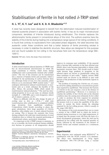
Bhadeshia et al.<strong>Stabilisation</strong> <strong>of</strong> <strong>ferrite</strong> <strong>in</strong> <strong>hot</strong> <strong>rolled</strong> d-<strong>TRIP</strong> <strong>steel</strong>push rod ‘BAHR DIL805’ high speed dilatometer withradio frequency <strong>in</strong>duction heat<strong>in</strong>g; the equipment hasbeen described elsewhere. 14 The sample temperature ismeasured by a thermocouple welded to its surface us<strong>in</strong>ga precision welder and jig supplied by the dilatometermanufacturer.The cast structure <strong>of</strong> the alloy identified as ‘Alloy 2’ <strong>in</strong>Table 1 has been <strong>in</strong>vestigated previously, 12 and hence,its designation is a ma<strong>in</strong>ta<strong>in</strong>ed here <strong>in</strong> order to avoidconfusion. The alloy is a new melt <strong>of</strong> the orig<strong>in</strong>al d-<strong>TRIP</strong> design, 1 needed to provide more material forexperiments; the design emerged from the neuralnetwork and genetic algorithm analysis, and the detailsare described fully <strong>in</strong> Ref. 1.1 a as cast microstructure show<strong>in</strong>g d-<strong>ferrite</strong> dendrites:dark regions are pearlitic, as illustrated at high magnification<strong>in</strong> <strong>in</strong>set, and b calculated equilibrium phase diagram(Alloy 2)furnace. In one case, represent<strong>in</strong>g the f<strong>in</strong>al alloy choice,the <strong>in</strong>got was reheated to 1200uC for rough roll<strong>in</strong>g tomake 25–30 mm slabs followed by air cool<strong>in</strong>g. Theseslabs were then reheated to 1200uC (heat<strong>in</strong>g rate to1200uC not monitored) and <strong>hot</strong> <strong>rolled</strong> to 3 mm <strong>in</strong>thickness with the temperature always ma<strong>in</strong>ta<strong>in</strong>ed above900uC followed by cool<strong>in</strong>g.Optical microscopy samples were prepared us<strong>in</strong>gstandard methods and etched <strong>in</strong> 2% nital. Heattreatments were conducted on cyl<strong>in</strong>drical dilatometricsamples <strong>of</strong> diameter 5 mm and length 10 mm us<strong>in</strong>g aTable 1 Compositions achieved dur<strong>in</strong>g manufacture, wt-%: alloys were manufactured as 34 kg <strong>in</strong>gots <strong>of</strong>10061706230 mm dimensions us<strong>in</strong>g vacuumfurnaceAlloy 2 Alloy 3 Alloy 4 Alloy 5 Alloy 6 Alloy 7C 0 . 37 0 . 40 0 . 40 0 . 41 0 . 37 0 . 39Si 0 . 23 0 . 26 0 . 74 0 . 26 0 . 76 0 . 77Mn 1 . 99 2 . 02 1 . 99 1 . 53 1 . 53 1 . 50Al 2 . 49 2 . 50 2 . 39 2 . 30 2 . 91 3 . 35Cu 0 . 49 … 0 . 49 0 . 49 … …P 0 . 02 0 . 02 0 . 02 0 . 02 … …S 0 . 0036 0 . 0013 0 . 0015 0 . 0014 0 . 0042 0 . 0045N 0 . 0048 0 . 0032 0 . 0024 0 . 0030 0 . 0020 0 . 0022Reheat<strong>in</strong>g experimentsThe microstructure <strong>of</strong> the as cast state <strong>of</strong> Alloy 2 isillustrated <strong>in</strong> Fig. 1 along with the calculated equilibriumphase diagram, which <strong>in</strong>dicated that a largefraction <strong>of</strong> the d-dendrites generated dur<strong>in</strong>g solidificationshould, under equilibrium conditions, persist dur<strong>in</strong>greheat<strong>in</strong>g at all temperatures.Samples <strong>of</strong> the <strong>steel</strong> were heated at 20uC s 21 to peaktemperatures <strong>of</strong> 800, 850, 900, 1000, 1100 and 1290uCfor 5 m<strong>in</strong>; further samples were similarly heated to 1360,1380 and 1400uC for 1 m<strong>in</strong>. After the small hold<strong>in</strong>gperiod, the samples were all quenched at 280uC s 21 .The heat treatments were conducted on the dilatometer.The heat<strong>in</strong>g rate and transformation times used here willbe different from those practised <strong>in</strong> an <strong>in</strong>dustrialenvironment, but the difference is unlikely to besignificant given the rapid rate <strong>of</strong> austenite formationat high temperatures.Metallographic studies were conducted on all thesamples, but only selected examples are presented here.Figure 2a shows the effect <strong>of</strong> heat<strong>in</strong>g to 800uC; there isclear evidence for the partial transformation <strong>of</strong> pearlite<strong>in</strong>to austenite, so that quench<strong>in</strong>g leads to martensite <strong>in</strong>the centres <strong>of</strong> the <strong>in</strong>terdendritic regions, where austenitestabilis<strong>in</strong>g elements are partitioned. 12 The austenite thatforms from pearlite then beg<strong>in</strong>s to penetrate the d-dendrites. The amount <strong>of</strong> austenite obta<strong>in</strong>ed is <strong>in</strong>consistentwith the equilibrium phase diagram (Fig. 1),although these observations are not surpris<strong>in</strong>g given thatthe austenite grows without the required level <strong>of</strong> solutepartition<strong>in</strong>g between the parent and product phases. 12By 950uC, the d-dendrite arms are no longer visible asuniform features, but on a microscopic scale, consist <strong>of</strong>martensite and remnants <strong>of</strong> <strong>ferrite</strong>, which are <strong>in</strong> the form<strong>of</strong> a network, presumably reflect<strong>in</strong>g segregation patterns(Fig. 2b). The sample heat treated to a peak temperature<strong>of</strong> 1100uC became almost fully austenitic, although theoverall structure rema<strong>in</strong>ed f<strong>in</strong>e because <strong>of</strong> the p<strong>in</strong>n<strong>in</strong>g <strong>of</strong>austenite gra<strong>in</strong> boundaries by remnants <strong>of</strong> <strong>ferrite</strong>(Fig. 3a). The <strong>ferrite</strong> content only recovered slightlywhen the peak temperature reached 1400uC, <strong>in</strong> a formrem<strong>in</strong>iscent <strong>of</strong> the d-<strong>ferrite</strong>, presumably follow<strong>in</strong>g thesolidification <strong>in</strong>duced chemical segregation patternsexist<strong>in</strong>g <strong>in</strong> the sample.It is evident the alloy would not be suitable for aprocess <strong>in</strong> which substantial d-<strong>ferrite</strong> must be reta<strong>in</strong>ed <strong>in</strong>the microstructure dur<strong>in</strong>g the <strong>hot</strong> roll<strong>in</strong>g process, eventhough the equilibrium phase diagram suggests otherwise.These large deviations from expectation make itdifficult to design suitable alloys; <strong>in</strong> previous work, 12 the526 Materials Science and Technology 2011 VOL 27 NO 2
Bhadeshia et al.<strong>Stabilisation</strong> <strong>of</strong> <strong>ferrite</strong> <strong>in</strong> <strong>hot</strong> <strong>rolled</strong> d-<strong>TRIP</strong> <strong>steel</strong>a4 Calculated quantities <strong>of</strong> austenite (cont<strong>in</strong>uous l<strong>in</strong>es)and <strong>ferrite</strong> (dashed l<strong>in</strong>es): Alloy 3 is plotted as po<strong>in</strong>ts<strong>in</strong> order to avoid confusion with Alloy 4; although onlyaustenite and <strong>ferrite</strong> are illustrated for clarity, liquidand cementite phases were allowed to existb2 a Alloy 2 heated to 800uC and quenched: light etch<strong>in</strong>gregions represent d-dendrites and darker regions aremixtures <strong>of</strong> martensite (austenite at 800uC) and <strong>ferrite</strong>,and b Alloy 2 heated to 900uC and quenched: arrowshows region which used to be d-<strong>ferrite</strong> and which isnow mixture <strong>of</strong> martensite and residual <strong>ferrite</strong>authors used DICTRA, which allows growth to bemodelled, to establish that the magnitudes <strong>of</strong> the k<strong>in</strong>eticeffects are reasonable, but the method requires assumptionsabout shape and scale, which make its use for alloydesign <strong>in</strong> the present context difficult. Therefore, apragmatic approach was adopted <strong>in</strong> which new alloyswere designed based essentially on experience, with thebroad aim <strong>of</strong> stabilis<strong>in</strong>g the <strong>ferrite</strong>.New alloysReferr<strong>in</strong>g to Table 1 and us<strong>in</strong>g Alloy 2 as a reference,Alloy 3 is based on the removal <strong>of</strong> copper, which is anaustenite stabilis<strong>in</strong>g element. The silicon concentration is<strong>in</strong>creased <strong>in</strong> Alloy 4 s<strong>in</strong>ce both alum<strong>in</strong>ium and silicon 15have the same c-loop form<strong>in</strong>g tendency and hencefavour the formation <strong>of</strong> d-<strong>ferrite</strong>. Alloy 5 is based on areduction <strong>in</strong> the manganese concentration and Alloy 6 isbased on a simultaneous reduction <strong>in</strong> Mn and <strong>in</strong>crease<strong>in</strong> the silicon and alum<strong>in</strong>ium concentrations. Alloy 7 hasa lower Mn, high Si and particularly high Al concentrations.Phase diagram calculations for the new alloys areillustrated <strong>in</strong> Fig. 4, which shows that the greatestpotential for <strong>in</strong>creas<strong>in</strong>g the stability <strong>of</strong> d-<strong>ferrite</strong> shouldbe <strong>in</strong> Alloys 6 and 7.Reheat<strong>in</strong>g experiments were conducted as describedfor Alloy 2, and quantitative data are presented <strong>in</strong>Fig. 6. d-<strong>ferrite</strong> did not persist <strong>in</strong> Alloys 2–5 ona3 Alloy 2 a heated to 1100uC and quenched, and b heated to 1400uC and quenched: arrow <strong>in</strong>dicates <strong>ferrite</strong> form<strong>in</strong>g <strong>in</strong>segregated regions <strong>of</strong> sample, <strong>in</strong> shapes rem<strong>in</strong>iscent <strong>of</strong> solidification structurebMaterials Science and Technology 2011 VOL 27 NO 2 527
Bhadeshia et al.<strong>Stabilisation</strong> <strong>of</strong> <strong>ferrite</strong> <strong>in</strong> <strong>hot</strong> <strong>rolled</strong> d-<strong>TRIP</strong> <strong>steel</strong>5 As cast microstructures <strong>of</strong> Alloys 3–7reheat<strong>in</strong>g, but dendrites <strong>of</strong> this phase survived <strong>in</strong> Alloys6 and 7, although the fraction <strong>of</strong> d-<strong>ferrite</strong> is much lessthan expected from equilibrium (Fig. 7).The microstructure after <strong>hot</strong> roll<strong>in</strong>g is illustrated <strong>in</strong>Fig. 8, where it is evident that there are two k<strong>in</strong>ds <strong>of</strong><strong>ferrite</strong> present: the first, the d-<strong>ferrite</strong>, which has beenelongated by deformation and then the allotriomorphic<strong>ferrite</strong>, which precipitates as the temperature dur<strong>in</strong>groll<strong>in</strong>g reduces towards 900uC. It is seen that thepresence <strong>of</strong> <strong>ferrite</strong> at all temperatures ma<strong>in</strong>ta<strong>in</strong>s a f<strong>in</strong>eaustenite and <strong>ferrite</strong> gra<strong>in</strong> structure.ConclusionsThe d-<strong>TRIP</strong> alloy system is based on the use <strong>of</strong> arelatively large concentration <strong>of</strong> alum<strong>in</strong>ium, whichshould lead to the formation <strong>of</strong> a substantial quantity<strong>of</strong> <strong>ferrite</strong> dendrites at equilibrium. Much <strong>of</strong> this <strong>ferrite</strong>,which forms dur<strong>in</strong>g solidification, should, <strong>in</strong> pr<strong>in</strong>ciple,resist transformation <strong>in</strong>to austenite, when the <strong>steel</strong> isheated to the high temperatures typical <strong>of</strong> <strong>hot</strong> roll<strong>in</strong>gdeformation. That it does not do so <strong>in</strong> practice has beenshown <strong>in</strong> previous work 12 to be due to the fact thataustenite is able to form by solid state transformation6 Volume percentages <strong>of</strong> optically resolvable <strong>ferrite</strong> forcast and reheated samples8 Alloy 7 after <strong>hot</strong> roll<strong>in</strong>ga b c7 Alloy 7 follow<strong>in</strong>g reheat<strong>in</strong>g to a 900uC, b 1000uC and c 1200uC528 Materials Science and Technology 2011 VOL 27 NO 2
Bhadeshia et al.<strong>Stabilisation</strong> <strong>of</strong> <strong>ferrite</strong> <strong>in</strong> <strong>hot</strong> <strong>rolled</strong> d-<strong>TRIP</strong> <strong>steel</strong>from d-<strong>ferrite</strong> without the required level <strong>of</strong> partition<strong>in</strong>g<strong>of</strong> solutes, particularly alum<strong>in</strong>ium.In the present work, it has been demonstrated thatsuitable alloys, <strong>in</strong> which the d-<strong>ferrite</strong> rema<strong>in</strong>s <strong>in</strong> themicrostructure over the range 900–1200uC, have beendesigned by <strong>in</strong>creas<strong>in</strong>g the alum<strong>in</strong>ium and siliconconcentrations, accompanied by a reduction <strong>in</strong> themanganese and copper contents. It has been possible,therefore, to produce a <strong>rolled</strong> variant <strong>of</strong> the alloy, whichwill be used <strong>in</strong> further <strong>in</strong>vestigations towards thecommercialisation <strong>of</strong> the <strong>steel</strong> on a cont<strong>in</strong>uous productionl<strong>in</strong>e.AcknowledgementsThe authors are grateful to Pr<strong>of</strong>essor H.-G. Lee,Graduate Institute <strong>of</strong> Ferrous Technology, Pohang,Korea, for the provision <strong>of</strong> laboratory facilities atPOSTECH, and to POSCO for help and support. Thepresent work is partly supported by the programmethrough the National Research Foundation <strong>of</strong> Korea,funded by the M<strong>in</strong>istry <strong>of</strong> Education, Science andTechnology (project no. R32-2008-000-10147-0).References1. S. Chatterjee, M. Murugananth and H. K. D. H. Bhadeshia:Mater. Sci. Technol., 2007, 23, 819–827.2. O. Matsumura, Y. Sakuma and H. Takechi: ‘Enhancement <strong>of</strong>elongation by reta<strong>in</strong>ed austenite <strong>in</strong> <strong>in</strong>tercritical annealed 0?4C–1?5Si–0?8Mn <strong>steel</strong>’, Trans. Iron Steel Inst. Jpn, 1987, 27, 570–579.3. O. Matsumura, Y. Sakuma and H. Takechi: ‘<strong>TRIP</strong> and its k<strong>in</strong>eticaspects <strong>in</strong> austempered 0?4C–1?5Si–0?8Mn <strong>steel</strong>’, Scr. Metall.,1987, 27, 1301–1306.4. Y. Sakuma, O. Matsumura and H. Takechi: ‘Mechanical–propertiesand reta<strong>in</strong>ed austenite <strong>in</strong> <strong>in</strong>tercritically heat-treated ba<strong>in</strong>itetransformed<strong>steel</strong> and their variation with Si and Mn additions’,Metall. Mater. Trans. A, 1991, 22A, 489–498.5. Y. Sakuma, O. Matsumura and O. Akisue: ‘Influence <strong>of</strong> C contentand anneal<strong>in</strong>g temperature on microstructure and mechanicalproperties<strong>of</strong> 400C transformed <strong>steel</strong> conta<strong>in</strong><strong>in</strong>g reta<strong>in</strong>ed austenite’,ISIJ Int., 1991, 31, 1348–1353.6. K. I. Sugimoto, A. Nagasaka, M. Kobayashi and S. I. Hashimoto:‘Effects <strong>of</strong> reta<strong>in</strong>ed austenite parameters on warm stretch-flangeability<strong>in</strong> <strong>TRIP</strong>-aided dual phase sheet <strong>steel</strong>s’, ISIJ Int., 1999, 39,56–63.7. H. K. D. H. Bhadeshia: ‘<strong>TRIP</strong>-assisted <strong>steel</strong>s?’, ISIJ Int., 2002, 42,1059–1060.8. P. J. Jacques: ‘Transformation-<strong>in</strong>duced plasticity for high strengthformable <strong>steel</strong>s’, Curr. Op<strong>in</strong>. Solid State Mater. Sci., 2004, 8, 259–265.9. B. C. de Cooman: ‘Structure–properties relationship <strong>in</strong> <strong>TRIP</strong> <strong>steel</strong>sconta<strong>in</strong><strong>in</strong>g carbide-free ba<strong>in</strong>ite’, Curr. Op<strong>in</strong>. Solid State Mater.Sci., 2004, 8, 285–303.10. W. W. Gerberich, G. Thomas, E. R. Parker and V. F. Zackay:‘Metastable austenites: decomposition and strength’, Proc. 2nd Int.Conf. on ‘Strength <strong>of</strong> metals and alloys’, Pacific Grove, CA, USA,August–September 1970, ASM International, 894–899.11. M. Santella, S. S. Babu, B. W. Riemer and Z. Fang: ‘Influence <strong>of</strong>microstructure on the properties <strong>of</strong> resistance spot welds’, <strong>in</strong>‘Trends <strong>in</strong> weld<strong>in</strong>g research’, (ed. S. A. David et al.), 605–609; 1999,Materials Park, OH, ASM International.12. H. L. Yi, S. K. Ghosh, W. J. Liu, K. Y. Lee and H. K. D. H.Bhadeshia: ‘Nonequilibrium solidification and <strong>ferrite</strong> <strong>in</strong> d-<strong>TRIP</strong><strong>steel</strong>’, Mater. Sci. Technol., 2010, 26, (7), 817–823.13. NPL: ‘MTDATA’; 2006, Tedd<strong>in</strong>gton, NPL.14. H.-S. Yang and H. K. D. H. Bhadeshia: ‘Uncerta<strong>in</strong>ties <strong>in</strong> thedilatometric determ<strong>in</strong>ation <strong>of</strong> the martensite-start temperature’,Mater. Sci. Technol., 2007, 23, 556–560.15. G. G. Bentle and W. P. Fishel: ‘Gamma loop studies <strong>in</strong> the Fe–Siand Fe–Si–Ti systems’, Trans. Am. Inst. M<strong>in</strong>. Metall. Eng., 1956,206, 1345–1348.Materials Science and Technology 2011 VOL 27 NO 2 529