SanDisk SD Card
SanDisk SD Card
SanDisk SD Card

Create successful ePaper yourself
Turn your PDF publications into a flip-book with our unique Google optimized e-Paper software.
Revision 2.2<strong>SanDisk</strong> <strong>SD</strong> <strong>Card</strong> Product Manual5.5 Data Write...............................................................................................5-35.6 Erase and Write Protect Management.....................................................5-45.7 Read CID/C<strong>SD</strong> Registers .......................................................................5-55.8 Reset Sequence.......................................................................................5-55.9 Clock Control .........................................................................................5-55.10 Error Conditions ....................................................................................5-65.11 Memory Array Partitioning....................................................................5-75.12 <strong>Card</strong> Lock/Unlock .................................................................................5-75.13 Application-specific Commands............................................................5-75.14 Copyright Protection Commands...........................................................5-75.15 Switch Function Command ...................................................................5-75.16 High-speed Mode (25MB/sec interface speed)......................................5-75.17 SPI Command Set..................................................................................5-85.18 Responses ............................................................................................5-125.19 Data Tokens .........................................................................................5-145.20 Data Error Token .................................................................................5-155.21 Clearing Status Bits .............................................................................5-155.22 <strong>Card</strong> Registers......................................................................................5-175.23 SPI Bus Timing Diagrams ...................................................................5-175.24 Timing Values......................................................................................5-195.25 SPI Electrical Interface........................................................................5-205.26 SPI Bus Operating Conditions.............................................................5-205.27 Bus Timing ..........................................................................................5-20Appendix A Ordering Information...............................................................A-1Appendix B <strong>SanDisk</strong> Worldwide Sales Offices........................................... B-1Appendix C Limited Warranty..................................................................... C-1Appendix D Disclaimer of Liability ............................................................D-1Appendix E Application Note...................................................................... E-1© 2004 <strong>SanDisk</strong> Corporation iii
Revision 2.2Chapter 1 – Introduction<strong>SanDisk</strong> <strong>SD</strong> <strong>Card</strong> Product Manual1 Introduction1.1 General DescriptionThe <strong>SanDisk</strong> Secure Digital (<strong>SD</strong>) <strong>Card</strong> is a flash-based memory card specifically designedto meet the security, capacity, performance and environmental requirements inherent innext generation mobile phones and consumer electronic devices. The <strong>SanDisk</strong> <strong>SD</strong> <strong>Card</strong>includes a copyright protection mechanism that complies with the security of the <strong>SD</strong>MIstandard, and is faster and capable of higher memory capacity. The <strong>SD</strong> <strong>Card</strong> securitysystem uses mutual authentication and a “new cipher algorithm” to protect against illegalusage of the card content. Unsecured access to the user‘s own content is also available. Thephysical form factor: pin assignment and data transfer protocol, with some additions, areforward compatible with the <strong>SD</strong> <strong>Card</strong>.<strong>SanDisk</strong> <strong>SD</strong> <strong>Card</strong> communication is based on an advanced nine-pin interface (clock,command, 4xData and 3xPower lines) designed to operate in a low voltage range. Thecommunication protocol is defined as part of this specification. The <strong>SD</strong> <strong>Card</strong> host interfacesupports regular MultiMedia<strong>Card</strong> operation as well. In other words, MultiMedia<strong>Card</strong>forward compatibility was kept. The main difference between the <strong>SD</strong> <strong>Card</strong> andMultiMedia<strong>Card</strong> is the initialization process. Matsushita Electric Company (MEI), ToshibaCorporation, and <strong>SanDisk</strong> Corporation defined the <strong>SD</strong> <strong>Card</strong> Specification originally.Currently, the Secure Digital Association (<strong>SD</strong>A) controls the specifications. The <strong>SanDisk</strong><strong>SD</strong> <strong>Card</strong> was designed to be compatible with the <strong>SD</strong> <strong>Card</strong> Physical Specification.The <strong>SD</strong> <strong>Card</strong> Interface allows for easy integration into any design, regardless ofmicroprocessor used. For compatibility with existing controllers, the <strong>SanDisk</strong> <strong>SD</strong> <strong>Card</strong>offers, in addition to the <strong>SD</strong> <strong>Card</strong> Interface, an alternate communication protocol based onthe SPI standard.Currently, the <strong>SanDisk</strong> <strong>SD</strong> <strong>Card</strong> provides up to 1024 million bytes of memory using flashmemory chips, which were designed especially for use in mass storage applications. Inaddition to the mass storage specific flash memory chip, the <strong>SD</strong> <strong>Card</strong> includes an on-cardintelligent controller which manages interface protocols, security algorithms for copyrightprotection, data storage and retrieval, as well as Error Correction Code (ECC) algorithms,defect handling and diagnostics, power management and clock control.Figure 1-1<strong>SanDisk</strong> <strong>SD</strong> <strong>Card</strong> Block Diagram<strong>SD</strong> Bus/SPI BusInterface<strong>SanDisk</strong>Single ChipControllerData In/OutControlFlashModules<strong>SanDisk</strong> <strong>SD</strong> <strong>Card</strong>© 2004 <strong>SanDisk</strong> Corporation 1-1 12/08/04
Revision 2.2Chapter 1 – Introduction<strong>SanDisk</strong> <strong>SD</strong> <strong>Card</strong> Product Manual1.2 Features<strong>SanDisk</strong> <strong>SD</strong> <strong>Card</strong> features include:►Up to 2-GB of data storage►<strong>SD</strong>-protocol compatible►Supports SPI mode► Targeted for portable and stationary applications for secured (copyrights protected) andunsecured data storage►Voltage rangeBasic communication (CMD0, CMD15, CMD55, ACMD41): 2.0 to 3.6VOther commands and memory access: 2.7 to 3.6V► Variable clock rate 0-25 MHz (default), 0-50MHz (high-speed)►Data transfer rateUp to 50 MB/sec data transfer rate (using 4 parallel data lines)Maximum data rate with up to 10 cards►Correction of memory-field errors►Copyrights Protection mechanismComplies with highest security of <strong>SD</strong>MI standard►Password-protection (specific models only)►Write Protect using mechanical switch►Built-in write protection features (permanent and temporary)►<strong>Card</strong> detection (Insertion/Removal)►Application-specific commands►Comfortable erase mechanism1.3 <strong>SD</strong> <strong>Card</strong> Standard<strong>SanDisk</strong> <strong>SD</strong> cards are fully compatible with the <strong>SD</strong> <strong>Card</strong> Physical Layer SystemSpecification, Version 1.10. This specification is available from the <strong>SD</strong> <strong>Card</strong> Association.<strong>SD</strong> Association719 San Benito St., Suite CHollister, CA 95023 USAPhone: +1 831-636-7322FAX: +1 831-623-2248E-mail: president@sdcard.orgURL: http://www.sdcard.org© 2004 <strong>SanDisk</strong> Corporation 1-2 12/08/04
Revision 2.2Chapter 1 – Introduction<strong>SanDisk</strong> <strong>SD</strong> <strong>Card</strong> Product Manual1.4 Functional Description<strong>SanDisk</strong> <strong>SD</strong> cards contain a high-level, intelligent subsystem as shown in Figure 1-1. Thisintelligent (microprocessor) subsystem provides many capabilities not found in other typesof memory cards. These capabilities include:• Host independence from details of erasing and programming flash memory• Sophisticated system for managing defects (analogous to systems found in magneticdisk drives)• Sophisticated system for error recovery including a powerful error correction code(ECC)• Power management for low-power operation1.5 Independent Flash TechnologyThe 512-byte sector size of the <strong>SanDisk</strong> <strong>SD</strong> <strong>Card</strong> is the same as that in an IDE magneticdisk drive. To write or read a sector (or multiple sectors), the host computer softwaresimply issues a read or write command to the <strong>SD</strong> <strong>Card</strong>. This command contains theaddress. The host software then waits for the command to complete. The host softwaredoes not get involved in the details of how the flash memory is erased, programmed orread. This is extremely important as flash devices are expected to get increasingly complexin the future. Because the <strong>SD</strong> <strong>Card</strong> uses an intelligent on-board controller, the host systemsoftware will not require changing as new flash memory evolves. In other words, systemsthat support the <strong>SD</strong> <strong>Card</strong> today will be able to access future <strong>SD</strong> cards built with new flashtechnology without having to update or change host software.1.6 Defect and Error Management<strong>SanDisk</strong> <strong>SD</strong> cards contain a sophisticated defect-and-error management system. Thissystem is analogous to the systems found in magnetic disk drives and in many cases offersenhancements. For instance, disk drives do not typically perform a read after write toconfirm the data is written correctly because of the performance penalty that would beincurred. <strong>SD</strong> cards do a read after write under margin conditions to verify that the data iswritten correctly. In the rare case that a bit is found to be defective, <strong>SD</strong> cards replace thisbad bit with a spare bit within the sector header. If necessary, <strong>SD</strong> cards will even replacethe entire sector with a spare sector. This is completely transparent to the host and does notconsume any user data space.The <strong>SD</strong> <strong>Card</strong>’s soft error rate specification is much better than the magnetic disk drivespecification. In the extremely rare case a read error does occur, <strong>SD</strong> cards have innovativealgorithms to recover the data. This is similar to using retries on a disk drive but is muchmore sophisticated. The last line of defense is to employ a powerful ECC to correct thedata. If ECC is used to recover data, defective bits are replaced with spare bits to ensurethey do not cause any future problems. These defect and error management systemscoupled with the solid-state construction give <strong>SD</strong> cards unparalleled reliability.© 2004 <strong>SanDisk</strong> Corporation 1-3 12/08/04
Revision 2.2Chapter 1 – Introduction<strong>SanDisk</strong> <strong>SD</strong> <strong>Card</strong> Product Manual1.7 Copyright ProtectionA detailed description of the Copyright Protection mechanism and related security <strong>SD</strong> <strong>Card</strong>commands can be found in the <strong>SD</strong> Security Specification from the <strong>SD</strong> Association. All <strong>SD</strong><strong>Card</strong> security-related commands operate in the data transfer mode.As defined in the <strong>SD</strong>MI specification, data content saved in the card is already encryptedand passes transparently to and from the card. No operation is done on the data and there isno restriction to read the data at any time. Associated with every data packet (e.g., a song)that is saved in the unprotected memory, there is special data that is saved in a protectedmemory area for any access (Read, Write or Erase command) to or from the data in theprotected area.For an authentication procedure is done between the card and the connected device, eitherthe LCM (PC for example) or the PD (portable device, such as <strong>SD</strong> player). After theauthentication process passes, the card is ready to accept or give data from/to the connecteddevice. While the card is in the secured mode of operation (after the authenticationsucceeded) the argument and the associated data that is sent to the card or read from thecard are encrypted. At the end of the Read, Write or Erase operation, the card gets outautomatically of its secured mode.1.8 Endurance<strong>SanDisk</strong> <strong>SD</strong> cards have an endurance specification for each sector of 100,000 writes typical(reading a logical sector is unlimited). This far exceeds what is typically required in almostall <strong>SD</strong> <strong>Card</strong> applications. Therefore, extremely heavy use of the card in cellular phones,personal communicators, pagers and voice recorders will use only a fraction of the totalendurance over the device’s lifetime. For instance—it would take over 10 years to wear outan area on an <strong>SD</strong> <strong>Card</strong> based on a file of any size (from 512 bytes to maximum capacity)being rewritten 3 times per hour, 8 hours a day, 365 days per year.With typical applications, the endurance limit is not of any practical concern to the vastmajority of users.1.9 Wear LevelingWear leveling is an intrinsic part of the erase pooling functionality of the <strong>SD</strong> <strong>Card</strong>, usingNAND memory. The Wear Level command is supported as a NOP operation to maintainbackward compatibility with existing software utilities.1.10 Automatic Sleep ModeA unique feature of the <strong>SanDisk</strong> <strong>SD</strong> <strong>Card</strong> is automatic entrance and exit from sleep mode.Upon completion of an operation, the card enters the sleep mode to conserve power if nofurther commands are received in less than five milliseconds (ms). The host does not haveto take any action for this to occur. However, in order to achieve the lowest sleep current,the host needs to shut down its clock to the card. In most systems, the <strong>SD</strong> card is in sleepmode except when the host is accessing it, thus conserving power.When the host is ready to access the card in sleep mode, any command issued to it willcause it to exit sleep, and respond.© 2004 <strong>SanDisk</strong> Corporation 1-4 12/08/04
Revision 2.2Chapter 1 – Introduction<strong>SanDisk</strong> <strong>SD</strong> <strong>Card</strong> Product Manual1.11 Hot InsertionSupport for hot insertion will be required on the host but will be supported through theconnector. Connector manufacturers will provide connectors that have power-pins longenough to be powered before contact is made with the other pins. This approach is similarto that used in PCMCIA and MMCA devices to allow for hot insertion.1.12 <strong>SD</strong> <strong>Card</strong>—<strong>SD</strong> Bus ModeThe following sections provide valuable information on the <strong>SD</strong> <strong>Card</strong> in <strong>SD</strong> Bus mode.1.12.1 <strong>SD</strong> <strong>Card</strong> Standard ComplianceThe <strong>SD</strong> <strong>Card</strong> is fully compliant with <strong>SD</strong> <strong>Card</strong> Physical Layer Standard Specification v1.10.The structure of the <strong>Card</strong> Specific Data (C<strong>SD</strong>) register is compliant with C<strong>SD</strong> Structure1.0.1.12.2 Negotiating Operating ConditionsThe <strong>SD</strong> <strong>Card</strong> supports the operation condition verification sequence defined in the <strong>SD</strong> <strong>Card</strong>standard specifications. Should the <strong>SD</strong> <strong>Card</strong> host define an operating voltage range, whichis not supported by the <strong>SD</strong> <strong>Card</strong> it will put itself in an inactive state and ignore any buscommunication. The only way to get the card out of the inactive state is by powering itdown and up again.In Addition the host can explicitly send the card to the inactive state by using theGO_INACTIVE_STATE command.1.12.3 <strong>Card</strong> Acquisition and IdentificationThe <strong>SD</strong> <strong>Card</strong> bus is a single master (<strong>SD</strong> <strong>Card</strong> host application) and a multi-slaves (cards)bus. The Clock and Power lines are common to all cards on the bus. During theidentification process, the host accesses each card separately through its own commandlines. The <strong>SD</strong> <strong>Card</strong>’s CID Register is pre-programmed with a unique card identificationnumber, which is used during the identification procedure.In addition, the <strong>SD</strong> <strong>Card</strong> host can read the card’s CID Register using the READ_CIDcommand. The CID Register is programmed during the <strong>SD</strong> <strong>Card</strong> testing and formattingprocedure, on the manufacturing floor. The <strong>SD</strong> <strong>Card</strong> host can only read, and not write, thisregister.An internal pull-up resistor on the DAT3 line may be used for card detection(insertion/removal). The resistor can be disconnected during data transfer (usingACMD42). Additional practical card detection methods can be found in <strong>SD</strong> PhysicalSpecification’s application notes given by the <strong>SD</strong>A.1.12.4 <strong>Card</strong> StatusThe card status is separated into the following two fields:• <strong>Card</strong> Status is stored in a 32-bit status register that is sent as a data field in the cardresponse to host commands. The Status Register provides information about the card’scurrent state and completion codes for the last host command. The card status can beexplicitly read (polled) with the SEND_STATUS command.© 2004 <strong>SanDisk</strong> Corporation 1-5 12/08/04
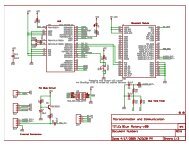
Revision 2.2Chapter 1 – Introduction<strong>SanDisk</strong> <strong>SD</strong> <strong>Card</strong> Product Manual• <strong>SD</strong> Status is stored in 512 bits that are sent as a single data block after it was requestedby the host using the <strong>SD</strong>_STATUS (ACMD13) command. <strong>SD</strong>_STATUS containsextended status bits that relate to BUS_WIDTH, security related bits and futurespecific applications.1.12.5 Memory Array PartitioningThe basic unit of data transfer to/from the <strong>SanDisk</strong> <strong>SD</strong> <strong>Card</strong> is one byte. All data transferoperations that require a block size always define block lengths as integer multiples ofbytes. Some special functions need other partition granularity. Figure 1-2 shows theMemory Array Partitioning.For block-oriented commands, the following definition is used:• Block—A unit related to block-oriented read and write commands. Its size is thenumber of bytes that are transferred when one block command is sent by the host. Thesize of a block is either programmable or fixed; information about allowed block sizesand the programmability is stored in the C<strong>SD</strong> Register.The granularity of the erasable units is, in general, not the same as for the block-orientedcommands:• Sector—A unit related to the erase commands. Its size is the number of blocks that areerased in one portion. The size of a sector is fixed for each device. The informationabout the sector size (in blocks) is stored in the C<strong>SD</strong> Register.For devices that include write protection, the following definition is used:• WP Group—A minimal unit that may have individual write protection. Its size is thenumber of groups to be write protected by one bit. The size of a WP group is fixed foreach device. The information about the size is stored in the C<strong>SD</strong> Register.© 2004 <strong>SanDisk</strong> Corporation 1-6 12/08/04
Revision 2.2Chapter 1 – Introduction<strong>SanDisk</strong> <strong>SD</strong> <strong>Card</strong> Product ManualFigure 1-2Memory Array Partitioning<strong>SanDisk</strong> <strong>SD</strong> Memory <strong>Card</strong>WP Group 0Sector 1Block 0Block 1Block 2Block nSector 2Sector 3Sector nWP Group 1WP Group 2Protected Area (Copyright Protection)Sector 1Block 0Block 1Block 2Block nSector nTable 1-1 Memory Array Structures Summary 1Part No.BlockSize(Bytes)Data Area +Protected size(Blocks)Protected Area 2 size(Blocks)User Area(Blocks0<strong>SD</strong><strong>SD</strong>H-2048 512 4,011,520 40,448 3,971,072<strong>SD</strong><strong>SD</strong>J-2048 512 4,011,520 40,448 3,971,072<strong>SD</strong><strong>SD</strong>X3-1024 512 2,004,480 20,480 1,984,000<strong>SD</strong><strong>SD</strong>H-1024 512 2,004,480 20,480 1,984,000<strong>SD</strong><strong>SD</strong>J-1024 512 2,004,480 20,480 1,984,000<strong>SD</strong><strong>SD</strong>H-512 512 1,001,216 10,240 990,976<strong>SD</strong><strong>SD</strong>J-512 512 1,001,216 10,240 990,976<strong>SD</strong><strong>SD</strong>H-256 512 499,456 5,376 494,080<strong>SD</strong><strong>SD</strong>J-256 512 499,456 5,376 494,080<strong>SD</strong><strong>SD</strong>J-128 512 248,640 2,624 246,016<strong>SD</strong><strong>SD</strong>J-64 512 123,232 1,376 121,8561 All measurements are in units per card.2 The part of the card that relates to the secured copyright management and has separate DOS partitioningincluding sectors and blocks. The card write-protection mechanism does not affect this area.© 2004 <strong>SanDisk</strong> Corporation 1-7 12/08/04
Revision 2.2Chapter 1 – Introduction<strong>SanDisk</strong> <strong>SD</strong> <strong>Card</strong> Product ManualPart No.BlockSize(Bytes)Data Area +Protected size(Blocks)Protected Area 2 size(Blocks)User Area(Blocks0<strong>SD</strong><strong>SD</strong>J-32 512 60,512 736 59,776<strong>SD</strong><strong>SD</strong>B-16 512 29,152 352 28,8001.12.6 Read/Write OperationsThe <strong>SD</strong> <strong>Card</strong> supports two read/write modes as shown in Figure 1-3 and defined in Table1-2.Figure 1-3Data Transfer FormatsSingle Block ModeMisalignment ErrorMemorySectorsMemorySectorsMemorySectorsMemorySectorsMemorySectorsMemorySectorsMemorySectorsMemorySectorsStart Address(Read)MemorySectorsStart Address(Write)Multiple Block ModeMemorySectorsMemorySectorsMemorySectorsStart Address(Read/Write)MemorySectorsMemorySectorsWriteReadStart Address Stop StartStopTable 1-2Mode DefinitionsModeSingle BlockMultiple BlockDescriptionIn this mode the host reads or writes one data block in a pre-specified length. Thedata block transmission is protected with 16-bit CRC that is generated by thesending unit and checked by the receiving unit.The block length for read operations is limited by the device sector size (512 bytes)but can be as small as a single byte. Misalignment is not allowed. Every data blockmust be contained in a single physical sector.The block length for write operations must be identical to the sector size and thestart address aligned to a sector boundary.This mode is similar to the single block mode, except for the host can read/writemultiple data blocks (all have the same length) that are stored or retrieved fromcontiguous memory addresses starting at the address specified in the command.The operation is terminated with a stop transmission command.Misalignment and block length restrictions apply to multiple blocks and are identicalto the single block read/write operations.1.12.7 Data Transfer RateThe <strong>SD</strong> <strong>Card</strong> can be operated using either a single data line (DAT0) or four data lines(DAT0-DAT3) for data transfer. The maximum data transfer rate for a single data line is 50-Mb per second, and 200-Mb (25 MB) per second using four data lines.© 2004 <strong>SanDisk</strong> Corporation 1-8 12/08/04
Revision 2.2Chapter 1 – Introduction<strong>SanDisk</strong> <strong>SD</strong> <strong>Card</strong> Product Manual1.12.8 Data Protection in the Flash <strong>Card</strong>Every sector is protected with an error correction code (ECC). The ECC is generated (inthe memory card) when the sectors are written and validated when the data is read. Ifdefects are found, the data is corrected prior to transmission to the host.1.12.9 Write ProtectionTwo-card level write-protection options are available: permanent and temporary. Both canbe set using the PROGRAM_C<strong>SD</strong> command (refer to C<strong>SD</strong> Programming). The permanentwrite-protect bit, once set, cannot be cleared. This feature is implemented in the <strong>SD</strong> <strong>Card</strong>controller firmware and not with a physical OTP cell.Use the Write Protect (WP) Switch located on the card’s side edge to prevent the host fromwriting to or erasing data on the card. The WP switch does not have any influence on theinternal Permanent or Temporary WP bits in the C<strong>SD</strong> Register.1.12.10 Copy BitThe copy bit can be used to mark an <strong>SD</strong> <strong>Card</strong> content as an original or a copy. The copybit of the card is programmed as a copy when testing and formatting are performed duringmanufacturing. When set, the copy bit in the C<strong>SD</strong> Register is a copy and cannot be cleared.The card is available with the copy-bit set or cleared. If the bit is set, it indicates that thecard is a master. This feature is implemented in the card’s controller firmware and not witha physical OTP cell.1.12.11 C<strong>SD</strong> RegisterAll <strong>SD</strong> <strong>Card</strong> configuration information is stored in the C<strong>SD</strong> Register. The MSB bytes ofthe register contain manufacturer data and the two least significant bytes contain the hostcontrolleddata: the card copy/write protection, and the user file format.The host can read the C<strong>SD</strong> Register and alter the host-controlled data bytes using theSEND_C<strong>SD</strong> and PROGRAM_C<strong>SD</strong> commands.1.13 SPI ModeThe SPI mode is a secondary communication protocol for <strong>SD</strong> cards. This mode is a subsetof the <strong>SD</strong> Protocol, designed to communicate with an SPI channel, commonly found inMotorola and other vendors’ microcontrollers.Table 1-3 SPI ModeFunctionNegotiating Operating Conditions<strong>Card</strong> Acquisition and IdentificationDescriptionThe operating condition negotiation function of the <strong>SD</strong> <strong>Card</strong> busis supported differently in SPI mode by using the READ_OCR(CMD58) command. The host works within the valid voltagerange (2.7 to 3.6 v) of the card or put the card in inactive stateby sending a GO_INACTIVE command to the card.The host must know the number of cards currently connected onthe bus. Specific card selection is done via the CS signal(CD/DAT3). The internal pull-up resistor on the CD/DAT3 linemay be used for card detection (insertion/removal). Additionalpractical card detection methods can be found in <strong>SD</strong> PhysicalSpecification’s Application Notes given by the <strong>SD</strong>A.© 2004 <strong>SanDisk</strong> Corporation 1-9 12/08/04
Revision 2.2Chapter 1 – Introduction<strong>SanDisk</strong> <strong>SD</strong> <strong>Card</strong> Product ManualFunctionDescription<strong>Card</strong> StatusMemory Array PartitioningRead/Write OperationsData Transfer RateData Protection in the <strong>SD</strong> <strong>Card</strong>EraseWrite ProtectionCopyright ProtectionIn SPI mode, only 16 bits containing errors relevant to SPI modecan be read out of the 32-bit Status Register. The <strong>SD</strong>_STATUScan be read using ACMD13, the same as in <strong>SD</strong> mode.Memory partitioning in SPI mode is equivalent to <strong>SD</strong> mode. Allread and write commands are byte addressable.In SPI mode, single and multiple block data transfers aresupported.Same as in <strong>SD</strong> mode.Same as in <strong>SD</strong> mode.Same as in <strong>SD</strong> mode.Same as in <strong>SD</strong> mode.Same as in <strong>SD</strong> mode.© 2004 <strong>SanDisk</strong> Corporation 1-10 12/08/04
Revision 2.2Chapter 2 – Product Specifications<strong>SanDisk</strong> <strong>SD</strong> <strong>Card</strong> Product Manual2 Product Specifications2.1 OverviewIn this section, all values are defined at an ambient temperature and nominal supply voltageunless otherwise stated.2.2 System Environmental SpecificationsTable 2-1 defines the environmental specifications for the <strong>SanDisk</strong> <strong>SD</strong> <strong>Card</strong>.Table 2-1 Environmental Specification SummaryTemperatureHumidityE<strong>SD</strong> ProtectionOperatingNon-operatingOperatingNon-operatingContact PadsNon Contact Pad Area-25° C to 85° C-40° C to 85° C25% to 95%, non condensing25% to 95%, non condensing+/- 4kV, Human body modelaccording to ANSI EOS/E<strong>SD</strong>-S5.1-1998+/- 8kV (coupling plane discharge)+/- 15kV (air discharge)Human body model per IEC61000-4-2.2.3 Reliability and DurabilityTable 2-2DurabilityBendingTorqueDrop TestReliability and Durability Specifications10,000 mating cycles10N0.15N.m or ±2.5 deg.1.5m free fallUV Light Exposure UV: 254nm, 15Ws/cm2 according to ISO 7816-1Visual Inspection/Shape and FormMinimum Moving Force of WP SwitchWP Switch CyclesNo warpage; no mold skin; complete form; nocavities; surface smoothness ≤ -0.1 mm/cm2 withincontour; no cracks; no pollution (oil, dust, etc.)40 gf (ensures that the WP switch will not slide while itis inserted in the connector).Minimum 1,000 Cycles @ slide force 0.4N to 5N© 2004 <strong>SanDisk</strong> Corporation 2-1 12/08/04
Revision 2.2Chapter 2 – Product Specifications<strong>SanDisk</strong> <strong>SD</strong> <strong>Card</strong> Product Manual2.4 Typical <strong>Card</strong> Power RequirementsTable 2-3<strong>Card</strong> Power Requirements (Ta=25°C@3.0V)VDD (ripple: max, 60mV peak-to-peak)2.7 V – 3.6 VValue Measurement AverageSleep 250 uA MaxRead 65 mA MaxWrite 75 mA Max2.5 System PerformanceAll performance values for the <strong>SD</strong> <strong>Card</strong> in Table 2-4 are under the following conditions:• Voltage range 2.7 V to 3.6 V• Temperature -25° C to 85° C• Independent of the <strong>SD</strong> <strong>Card</strong> clock frequencyTable 2-4 System PerformanceTiming Typical MaximumBlock Read Access Time 0.5 ms 100 msBlock Write Access Time 0.5 ms 250 msCMD1 to Ready afterPower-up50 ms 500 msSleep to Ready 1 ms 2 ms2.6 System Reliability and MaintenanceTable 2-5MTBFReliability and Maintenance Specifications>1,000,000 hoursPreventative MaintenanceData ReliabilityEnduranceNone
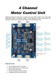
Revision 2.2Chapter 2 – Product Specifications<strong>SanDisk</strong> <strong>SD</strong> <strong>Card</strong> Product Manual2.7 Physical SpecificationsRefer to Table 2-6 and Figure 2-1 for <strong>SD</strong> card’s physical specifications and dimensions.Table 2-6 <strong>SD</strong> Memory <strong>Card</strong> Physical Specification SummarySpecification<strong>SD</strong> <strong>Card</strong>WeightLengthWidthThickness2.0 g. maximum32 mm ± 0.1 mm24 mm ± 0.1 mm2.1 mm ± 0.15 mm (in substrate area only, 2.25 mm maximum)Figure 2-1<strong>SD</strong> Memory <strong>Card</strong> Dimensions (Bottom View)© 2004 <strong>SanDisk</strong> Corporation 2-3 12/08/04
Revision 2.2Chapter 2 – Product Specifications<strong>SanDisk</strong> <strong>SD</strong> <strong>Card</strong> Product ManualFigure 2-2<strong>SD</strong> Memory <strong>Card</strong> Dimensions© 2004 <strong>SanDisk</strong> Corporation 2-4 12/08/04
Revision 2.2Chapter 2 – Product Specifications<strong>SanDisk</strong> <strong>SD</strong> <strong>Card</strong> Product ManualFigure 2-3<strong>SD</strong> Memory <strong>Card</strong> Dimensions (Top View)2.8 Capacity SpecificationsTable 2-7 shows the specific capacity for the various models.Table 2-7 Model Capacity SummaryModel No.Capacity<strong>SD</strong><strong>SD</strong>B-16<strong>SD</strong><strong>SD</strong>J-32<strong>SD</strong><strong>SD</strong>J-64<strong>SD</strong><strong>SD</strong>J-128<strong>SD</strong><strong>SD</strong>J-256<strong>SD</strong><strong>SD</strong>H-256<strong>SD</strong><strong>SD</strong>J-512<strong>SD</strong><strong>SD</strong>H-51216 MB32 MB64 MB128 MB256 MB256 MB512 MB512 MB© 2004 <strong>SanDisk</strong> Corporation 2-5 12/08/04
Revision 2.2Chapter 2 – Product Specifications<strong>SanDisk</strong> <strong>SD</strong> <strong>Card</strong> Product ManualModel No.Capacity<strong>SD</strong><strong>SD</strong>J-1024<strong>SD</strong><strong>SD</strong>H-1024<strong>SD</strong><strong>SD</strong>X3-1024<strong>SD</strong><strong>SD</strong>J-2048<strong>SD</strong><strong>SD</strong>H-20481024 MB1024 MB1024 MB2048 MB2048 MB© 2004 <strong>SanDisk</strong> Corporation 2-6 12/08/04
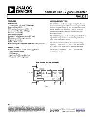
Revision 2.2Chapter 3 – <strong>SD</strong> <strong>Card</strong> Interface Description<strong>SD</strong> <strong>Card</strong> Product Manual3 <strong>SD</strong> <strong>Card</strong> Interface Description3.1 General Description of Pins and RegistersThe <strong>SanDisk</strong> <strong>SD</strong> <strong>Card</strong> has nine exposed contacts on one side as shown in Figure 3-1. Thehost is connected to the card using a dedicated 9-pin connector.Table 3-1<strong>SD</strong> <strong>Card</strong> Pad AssignmentPin No. Name Type 1 Description<strong>SD</strong> Mode1 CD/DAT3 2 I/O 3 , PP <strong>Card</strong> detect/Data line [Bit 3]2 CMD I/O, PP Command/Response3 V SS1 S Supply voltage ground4 V DD S Supply voltage5 CLK I Clock6 V SS2 S Supply voltage ground7 DAT0 I/O, PP Data line [Bit 0]8 DAT1 I/O, PP Data line [Bit 1]9 DAT2 I/O, PP Data line [Bit 2]SPI Mode1 CS I Chip Select (active low)2 DataIn I Host-to-card Commands and Data3 V SS1 S Supply voltage ground4 V DD S Supply voltage5 CLK I Clock6 V SS2 S Supply voltage ground7 DataOut O <strong>Card</strong>-to-host Data and Status8 RSV 4 --- Reserved9 RSV 5 --- Reserved1 Type Key: S=power supply; I=input; O=output using push-pull drivers; PP=I/O using push-pull drivers2 The extended DAT lines (DAT1-DAT3) are input on power up. They start to operate as DAT lines after theSET_BUS_WIDTH command. It is the responsibility of the host designer to connect external pullup resistors toall data lines even if only DAT0 is to be used. Otherwise, non-expected high current consumption may occur dueto the floating inputs of DAT1 & DAT2 (in case they are not used).3 After power up, this line is input with 50Kohm(+/-20Kohm) pull-up (can be used for card detection or SPI modeselection). The pull-up may be disconnected by the user, during regular data transfer, withSET_CLR_CARD_DETECT (ACMD42) command.4 The ‘RSV’ pins are floating inputs. It is the responsibility of the host designer to connect external pullup resistorsto those lines. Otherwise non-expected high current consumption may occur due to the floating inputs.5 Ibid.© 2004 <strong>SanDisk</strong> Corporation 3-1 12/08/04
Revision 2.2Chapter 3 – <strong>SD</strong> <strong>Card</strong> Interface Description<strong>SD</strong> <strong>Card</strong> Product ManualEach card has a set of information registers (refer to Table 3-3). Detailed descriptions areprovided in Section 3.5.Table 3-2<strong>SD</strong> <strong>Card</strong> RegistersName Width DescriptionCID 128 <strong>Card</strong> identification number: individual card number for identification.RCA 6 16 Relative card address: local system address of a card, dynamicallysuggested by the card and approved by the host during initialization.C<strong>SD</strong> 128 <strong>Card</strong> specific data: information about the card operation conditions.SCR 64 <strong>SD</strong> Configuration Register: information about the <strong>SD</strong> <strong>Card</strong>’s specialfeatures capabilities.OCR 32 Operation Condition RegisterThe host may reset the cards by switching the power supply off and on again. The card hasits own power-on detection circuitry that puts the card into an idle state after the power-on.The GO_IDLE (CMD0) command can also reset the card.Figure 3-1<strong>SD</strong> <strong>Card</strong> Architecture6 The RCA Register is not available in SPI mode.© 2004 <strong>SanDisk</strong> Corporation 3-2 12/08/04
Revision 2.2Chapter 3 – <strong>SD</strong> <strong>Card</strong> Interface Description<strong>SD</strong> <strong>Card</strong> Product Manual3.2 <strong>SD</strong> Bus TopologyThe <strong>SD</strong> Memory <strong>Card</strong> bus has six communication lines and three supply lines.• CMD• DAT0-3• CLK• VDD• VSS[1:2]The description of each signal is contained in Table 3-3.Table 3-3NameCMDDAT0-3CLKV DDV SS [1:2]MMC Bus Signal DescriptionsDescriptionCommand is a bi-directional signal. Host and card drivers are operating in pushpullmode.Data lines are bi-directional signals. Host and card drivers are operating in pushpullmode.Clock is a host to card signal. CLK operates in push-pull mode.Power supply line for all cards.Two ground lines.Figure 3-2 shows the bus topology of several cards with one host in <strong>SD</strong> Bus mode.Figure 3-2<strong>SD</strong> <strong>Card</strong> System Bus TopologyHOSTCLKVddVssD0-3(A),CMD(A)CLKVddVssD0-D3, CMD<strong>SD</strong> Memory<strong>Card</strong> (A)D0-3(B),CMD(B)CLKVddVssD0-D3, CMD<strong>SD</strong> Memory<strong>Card</strong> (B)D0-3(C)CMD(C)CLKVddVssD0, CS, CMDMultiMedia<strong>Card</strong>(C)D1&D2 NotConnected© 2004 <strong>SanDisk</strong> Corporation 3-3 12/08/04
Revision 2.2Chapter 3 – <strong>SD</strong> <strong>Card</strong> Interface Description<strong>SD</strong> <strong>Card</strong> Product ManualDuring the initialization process, commands are sent to each card individually, allowing theapplication to detect the cards and assign logical addresses to the physical slots. Data isalways sent to each card individually. However, to simplify the handling of the card stack,after initialization, all commands may be sent concurrently to all cards. Addressinginformation is provided in the command packet.The <strong>SD</strong> bus allows dynamic configuration of the number of data lines. After power-up, bydefault, the <strong>SD</strong> <strong>Card</strong> will use only DAT0 for data transfer. After initialization, the host canchange the bus width (number of active data lines). This feature allows and easy trade offbetween hardware cost and system performance.Figure 3-3Bus Circuitry DiagramR DATR CMDR WPWrite ProtectCMDDAT0-3<strong>SD</strong>MemoryC 1 C 2 C 3<strong>Card</strong>Host 1 2 3 4 5 6 7 89VssCLK<strong>SD</strong> Memory<strong>Card</strong>R DAT and R CMD are pull-up resistors protecting the CMD and DAT line against bus floatingwhen no card is inserted or all card drivers are in a hi-impedance mode.R WP is used for the Write Protect Switch. See Section 5.4.2 for the component values andconditions.3.2.1 Hot Insertion and RemovalHot insertion and removal are allowed; inserting or removing the <strong>SD</strong> <strong>Card</strong> to or from thebus will not damage the card. This also applies when the power is up.• The inserted card will be properly reset when CLK carries a clock frequency (f pp ).• Data transfer failures induced by removal/insertion should be detected by the busmaster using the CRC codes that suffix every bus transaction.3.2.2 Power Protection<strong>Card</strong>s can be inserted or removed to and from the bus without damage, however if one ofthe supply pins (V DD or V SS ) is not connected properly, the current is drawn through a dataline to supply the card.Data transfer operations are protected by CRC codes; therefore, the <strong>SD</strong> bus master candetect any bit changes induced by card insertion and removal. Also, the inserted card mustbe properly reset when CLK carries a clock frequency f PP .If the hot insertion feature is implemented in the host, the host must withstand a shortcutbetween V DD and V SS without damage.© 2004 <strong>SanDisk</strong> Corporation 3-4 12/08/04
Revision 2.2Chapter 3 – <strong>SD</strong> <strong>Card</strong> Interface Description<strong>SD</strong> <strong>Card</strong> Product Manual3.3 SPI Bus TopologyThe <strong>SD</strong> <strong>Card</strong> SPI Interface is compatible with SPI hosts available on the market. Similar toany other SPI device, the <strong>SD</strong> <strong>Card</strong> SPI channel consists of the following four signals:• CS—Host-to-card Chip Select signal• CLK—Host-to-card Clock signal• DataIn—Host-to-card Data signal• DataOut—<strong>Card</strong>-to-host Data signalAnother SPI common characteristic implemented in the <strong>SD</strong> <strong>Card</strong> are byte transfers. Alldata tokens are multiples of 8-bit bytes and always byte-aligned to the CS signal. The SPIstandard defines the physical link only and not the complete data transfer protocol. In SPIbus mode, the <strong>SD</strong> <strong>Card</strong> uses a subset of the <strong>SD</strong> <strong>Card</strong> protocol and command set.The <strong>SD</strong> <strong>Card</strong> identification and addressing algorithms are replaced by the hardware CSsignal. A card (slave) is selected for every command by asserting the CS signal (activelow). Refer to Figure 3-2.The CS signal must be continuously active for the duration of the SPI transaction(command, response and data). The only exception is card-programming time. At this timethe host can de-assert the CS signal without affecting the programming process.The bi-directional CMD and DAT lines are replaced by unidirectional dataIn and dataOutsignals. This eliminates the ability to execute commands while data is being read or writtenwhich prevents sequential multi read/write operations. The Stop Transmission commandcan be sent during data read. In the multi block write operation a Stop Transmission tokenis sent as the first byte of the data block.Figure 3-4<strong>SD</strong> <strong>Card</strong> Bus SystemPower SupplySPI Bus MasterCSCSSPI Bus (CLK, DataIn, DataOut)SPI <strong>Card</strong>SPI <strong>Card</strong>© 2004 <strong>SanDisk</strong> Corporation 3-5 12/08/04
Revision 2.2Chapter 3 – <strong>SD</strong> <strong>Card</strong> Interface Description<strong>SD</strong> <strong>Card</strong> Product Manual3.3.1 Power ProtectionSame as in <strong>SD</strong> <strong>Card</strong> Bus Mode.3.4 Electrical InterfaceThe following sections provide valuable information about the electrical interface.3.4.1 Power UpThe power-up of the <strong>SD</strong> <strong>Card</strong> bus is handled locally, in each <strong>SD</strong> <strong>Card</strong> and in the busmaster.Figure 3-5 Power-up DiagramSupply VoltageLogic working levelV DDmaxBus master supply voltageV DDminValid voltagerange forcommands CMD0,15, 55, andACMD41Valid voltagerange for allother commandsand memoryaccessPower-upTimeSupply Ramp-upTimetimeTimeout value for initialization process = 1 secondInitializationSequenceACMD41N CC ACMD N CC ACMD N CC4141CMD2Initialization delay:the max. of 1 ms,74 clock cyclesand supply rampuptimeOptional repetitions of ACMD1 until nocards respond with busy bit setAfter power up, including hot insertion (i.e., inserting a card when the bus is operating) the<strong>SD</strong> <strong>Card</strong> enters the idle state. During this state the <strong>SD</strong> <strong>Card</strong> ignores all bus transactionsuntil ACMD41 is received (ACMD command type shall always precede with CMD55).ACMD41 is a special synchronization command used to negotiate the operation voltagerange and to poll the cards until they are out of their power-up sequence. Besides theoperation voltage profile of the cards, the response to ACMD41 contains a busy flag,indicating that the card is still working on its power-up procedure and is not ready foridentification. This bit informs the host that the card is not ready. The host has to wait (andcontinue to poll the cards, each one on his turn) until this bit is cleared. The maximumperiod of power up procedure of single card shall not exceed one second.Getting individual cards, and the entire <strong>SD</strong> <strong>Card</strong> system, out of idle state is up to theresponsibility of the bus master. Since the power up time and the supply ramp up timedepend on application parameters such as the maximum number of <strong>SD</strong> <strong>Card</strong> s, the buslength and the power supply unit, the host must ensure that the power is built up to theoperating level (the same level which will be specified in ACMD41) before ACMD41 istransmitted.© 2004 <strong>SanDisk</strong> Corporation 3-6 12/08/04
Revision 2.2Chapter 3 – <strong>SD</strong> <strong>Card</strong> Interface Description<strong>SD</strong> <strong>Card</strong> Product ManualAfter power up, the host starts the clock and sends the initializing sequence on the CMDline. This sequence is a contiguous stream of logical ‘1’s. The sequence length is themaximum of 1msec, 74 clocks or the supply-ramp-up-time; the additional 10 clocks (overthe 64 clocks after what the card should be ready for communication) is provided toeliminate power-up synchronization problems.Every bus master shall have the capability to implement ACMD41 and CMD1. CMD1 willbe used to ask MultiMedia<strong>Card</strong>s to send their operation conditions. In any case theACMD41 or the CMD1 shall be send separately to each card accessing it through its ownCMD line.3.4.2 Bus Operating ConditionsSPI Mode bus operating conditions are identical to <strong>SD</strong> <strong>Card</strong> mode bus operatingconditions. Table 3-4 lists the power supply voltages. The CS (chip select) signal timing isidentical to the input signal timing (see Figure 3-8).Table 3-4Bus Operating Conditions SummaryParameter Symbol Min Max Unit RemarkGeneralPeak voltage on all lines --- -0.3 V DD + 0.3 VAll InputsInput Leakage Current --- -10 10 uAAll OutputsOutput Leakage Current --- -10 10 uAPower Supply Voltage 7Supply Voltage V DD 2.0 3.6 V CMD0, 15, 55,ACMD41 commandsV DD 2.7 3.6 V Except CMD0, 15, 55,ACMD41 commandsSupply voltage differentials(V SS1 , V SS2 )--- -0.3 0.3 VPower-up Time --- --- 250 mS From 0 V to V DD min.3.4.3 Bus Signal Line LoadThe total capacitance, C L , of the clock line in the <strong>SD</strong> <strong>Card</strong> bus is the sum of the bus-mastercapacitance (C HOST ), the bus capacitance (C BUS ) itself and the capacitance (C CARD ) of eachcard connected to this line:C L = C HOST + C BUS + N*C CARDWhere N is the number of connected cards. Requiring the sum of the host and buscapacitances not to exceed 30 pF for up to 10 cards, and 40 pF for up to 30 cards, thevalues in Table 3-4 must not be exceeded.7 The current consumption of any card during the power-up procedure must not exceed 10 mA.© 2004 <strong>SanDisk</strong> Corporation 3-7 12/08/04
Revision 2.2Chapter 3 – <strong>SD</strong> <strong>Card</strong> Interface Description<strong>SD</strong> <strong>Card</strong> Product ManualTable 3-5 Host and Bus Capacities 8Parameter Symbol Min. Max. Unit RemarkPull-up resistanceR CMD, 10 100 kΩ Prevents bus floatingR DATBus signal line capacitance C L --- 250 pF f PP < 5 MHz, 21 cardsBus signal line capacitance C L --- 100 pFSignal card capacitance C CARD --- 10 pFf PP < 20 MHz, 7 cardsMax. signal line inductance --- --- 16 nH f PP
Revision 2.2Chapter 3 – <strong>SD</strong> <strong>Card</strong> Interface Description<strong>SD</strong> <strong>Card</strong> Product Manual3.4.6 Bus Timing (default)Default dataIn/dataOut timing is illustrated in Figure 3-7; bus timing parameter values areshown in Table 3-7.Figure 3-7Data In/Out Referenced to Clock Timing (default)Table 3-7Bus Timing Parameter Values (default)Parameter Symbol Min Max Unit RemarkClock (CLK) – all values referred to min. V IH and max. V ILClock Freq. Data Transfer Mode f PP 0 25 MHz C L < 100 pF (7 cards)Clock Freq. Identification Mode 9 f OD 0 10 /10 400 kHz C L < 250 pF (21 cards)0Clock Low Time t WL 10 --- ns C L < 100 pF (7 cards)Clock High Time t WH 10 --- ns C L < 100 pF (7 cards)Clock Rise Time t TLH --- 10 ns C L < 100 pF (10 cards)Clock Fall Time t THL --- 10 ns C L < 100 pF (7 cards)Clock Low Time t WL 50 --- ns C L < 250 pF (21 cards)Clock High Time t WH 50 --- ns C L < 250 pF (21 cards)Clock Rise Time t TLH --- 50 ns C L < 250 pF (21 cards)Clock Fall Time t THL --- 50 ns C L < 250 pF (21 cards)Inputs CMD, DAT – referenced to CLKInput setup time t ISU 5 --- ns C L < 25 pF (1 card)Input hold time t IH 5 --- ns C L < 25 pF (1 card)Outputs CMD, DAT – referenced to CLK9 Low frequency required for MMC compatibility.10 0 Hz stops clock—given min. freq. range is for cases in which a continuous clock is required.© 2004 <strong>SanDisk</strong> Corporation 3-9 12/08/04
Revision 2.2Chapter 3 – <strong>SD</strong> <strong>Card</strong> Interface Description<strong>SD</strong> <strong>Card</strong> Product ManualParameter Symbol Min Max Unit RemarkClock (CLK) – all values referred to min. V IH and max. V ILOutput delay time during DataTransfer modeOutput delay time duringIdentification modet OSU 0 14 ns C L < 25 pF (1 card)t ODLY 0 50 ns C L < 25 pF (1 card)3.4.7 Bus Timing (high-speed mode)High-speed mode dataIn/dataOut timing is illustrated in Figure 3-8; bus timing parametervalues are shown in Table 3-8.Figure 3-8Data In/Out Referenced to Clock Timing (high-speed)Table 3-8Bus Timing Parameter Values (high-speed)Parameter Symbol Min Max Unit RemarkClock (CLK) – all values referred to min. V IH and max. V ILClock Freq. Data Transfer Mode f PP 0 50 MHzClock Low Time t WL 7 --- nsClock High Time t WH 7 --- nsClock Rise Time t TLH --- 3 nsClock Fall Time t THL --- 3 nsInputs CMD, DAT – referenced to CLKInput setup time t ISU 6 --- nsInput hold time t IH 2 --- nsOutputs CMD, DAT – referenced to CLKOutput delay time during DataTransfer modet ODLY --- 14 ns© 2004 <strong>SanDisk</strong> Corporation 3-10 12/08/04
Revision 2.2Chapter 3 – <strong>SD</strong> <strong>Card</strong> Interface Description<strong>SD</strong> <strong>Card</strong> Product ManualParameter Symbol Min Max Unit RemarkClock (CLK) – all values referred to min. V IH and max. V ILOutput hold time t OH 2.5 --- nsTotal system capacitance for C L --- 40 pFeach line 113.5 <strong>SD</strong> <strong>Card</strong> RegistersThere is a set of six registers within the card interface. The OCR, CID, C<strong>SD</strong>, and SCRregisters carry the card configuration information. The RCA Register holds the cardrelativecommunication address for the current session. The card status and <strong>SD</strong> statusregisters hold the communication protocol related status of the card.3.5.1 Operating Conditions RegisterThe 32-bit Operation Conditions Register (OCR) stores the V DD voltage profile of the<strong>SanDisk</strong> <strong>SD</strong> <strong>Card</strong>. The card is capable of executing the voltage recognition procedure(CMD1) with any standard <strong>SD</strong> <strong>Card</strong> host using operating voltages from 2 to 3.6 V.Accessing the data in the memory array, however, requires 2.7 to 3.6 V. The OCR showsthe voltage range in which the card data can be accessed. The structure of the OCRRegister is described in Table 3-9.Table 3-9Operating Conditions RegisterOCR Bit VDD Voltage Window OCR Bit VDD Voltage Window0-3 Reserved 15 2.7 to 2.84 1.6 to 1.7 16 2.8 to 2.95 1.7 to 1.8 17 2.9 to 3.06 1.8 to 1.9 18 3.0 to 3.17 1.9 to 2.0 19 3.1 to 3.28 2.0 to 2.1 20 3.2 to 3.39 2.1 to 2.2 21 3.3 to 3.410 2.2 to 2.3 22 3.4 to 3.511 2.3 to 2.4 23 3.5 to 3.612 2.4 to 2.5 24-30 Reserved13 2.5 to 2.6 31 <strong>Card</strong> power-up status bit14 2.6 to 2.711 In order to satisfy severe timing, the host will drive only one card.© 2004 <strong>SanDisk</strong> Corporation 3-11 12/08/04
Revision 2.2Chapter 3 – <strong>SD</strong> <strong>Card</strong> Interface Description<strong>SD</strong> <strong>Card</strong> Product Manual3.5.2 <strong>Card</strong> Identification RegisterThe <strong>Card</strong> Identification Register (CID) 12 is 16 bytes long and contains a unique cardidentification number as shown in Table 3-10. It is programmed during card manufacturingand cannot be changed by <strong>SD</strong> <strong>Card</strong> hosts.Table 3-10CID Register DefinitionsName Type Width CID-Slice CID Value CommentsManufacturer ID (MID) Binary 8 [127:120] 0x03 Manufacturer IDs arecontrolled andassigned by the <strong>SD</strong><strong>Card</strong> AssociationOEM/Application ID (OID) ASCII 16 [119:104] <strong>SD</strong> ASCII Code0x53, 0x44Product Name (PNM) ASCII 40 [103:64] <strong>SD</strong>02G<strong>SD</strong>01G<strong>SD</strong>512<strong>SD</strong>256<strong>SD</strong>128<strong>SD</strong>64<strong>SD</strong>32<strong>SD</strong>16Product Revision 14 BCD 8 [63:56] ProductRevision xxSerial Number (PSN) Binary 32 [55:24] Product SerialNumberIdentifies the cardOEM and/or the cardcontents. The OID isassigned by the3C. 13Five ASCIIcharacters longTwo binary-codeddecimal digits32-bit unsignedintegerReserved --- 4 [23:20] --- ---Manufacture Date Code(MDT)BCD 12 [19:8] Manufacturedate (for ex.April 2001=0x014)Manufacturingdate—yym (offsetfrom 2000)CRC7 checksum (CRC) Binary 7 [7:1] CRC7* CalculatedNot used, always “1” --- 1 [0.0] --- ---*The CRC checksum is computed by using the following formula:CRC Calculation: G(x)=x 7+3+1M(x)=(MID-MSB)*x 119 +…+(CIN-LSB)*x 0CRC[6…0]=Remainder[(M(x)*x 7 )/G(x)]12 The CID Register in the <strong>SD</strong> <strong>Card</strong> has a different structure than in the MultiMedia<strong>Card</strong>.13 3C represents the three <strong>SD</strong>A founding companies: Toshiba, <strong>SanDisk</strong>, and MEI.14 The product revision is composed of two binary-coded decimal (BCD) digits (4 bits ea.) representing and “n.m”revision number. The “n” is the most significant nibble and the “m” is the least significant nibble. Example: thePRV binary value filed for product revision (6.2) would be “01100010”.© 2004 <strong>SanDisk</strong> Corporation 3-12 12/08/04
Revision 2.2Chapter 3 – <strong>SD</strong> <strong>Card</strong> Interface Description<strong>SD</strong> <strong>Card</strong> Product Manual3.5.3 <strong>Card</strong> Specific Data RegisterThe <strong>Card</strong> Specific Data (C<strong>SD</strong>) Register configuration information is required to accessthe card data.In Table 3-11, the Cell Type column defines the C<strong>SD</strong> field as read-only (R), one-timeprogrammable (R/W) or erasable (R/W/E). The values are presented in “real world” unitsfor each field and coded according to the C<strong>SD</strong> structure.Table 3-11C<strong>SD</strong> Register FieldsField Width CellTypeC<strong>SD</strong>SliceC<strong>SD</strong> Value C<strong>SD</strong> Code DescriptionC<strong>SD</strong>_STRUCTURE2 R [127:126]1.0 0 C<strong>SD</strong> structure--- 6 R [125:120]TAAC 8 R [119:112]--- 000000b Reserved1.5 msec 00100110 Data readaccess time-1NSAC 8 R [111:104]0 00000000b Data readaccess time-2 inCLK cycles(NSAC*100)TRANS_SPEED8 R [103:96]Default 25MHz 0110010High-speed50MHz01011010Max. datatransfer rateCCC 12 R [95:84] All (inc. WP,lock/unlock)5F5<strong>Card</strong> commandclassesREAD_BL_LEN4 R [83:80] 2GUp to 1GAh9hMax. read datablock lengthREAD_BL_PARTIALWRITE_BLK_MISALIGNREAD_BLK_MISALIGN1 R [79:79] Yes 1b Partial blocksfor read allowed1 R [78:78] No 0b Write blockmisalignment1 R [77:77] No 0b Read blockmisalignmentDSR_IMP 1 R [76:76] No 0b DSRimplemented--- 2 R [75:74] --- 00b ReservedC_SIZE 12 R [73:62] 2 GB1 GB512 MB256 MB128 MB64 MB32 MB16 MBF24hF22hF1EhF13hF03hEDFh74Bh383hDevice sizeVDD_R_CURR_MINVDD_R_CURR_MAX3 R [61:59] 100 mA 111b Max. readcurrent @VDDmin.3 R [58:56] 80 mA 110b Max. readcurrent @VDD© 2004 <strong>SanDisk</strong> Corporation 3-13 12/08/04
Revision 2.2Chapter 3 – <strong>SD</strong> <strong>Card</strong> Interface Description<strong>SD</strong> <strong>Card</strong> Product ManualField Width CellTypeC<strong>SD</strong>SliceC<strong>SD</strong> Value C<strong>SD</strong> Code Descriptionmax.VDD_W_CURR_MINVDD_W_CURR_MAX3 R [55:53] 100 mA 111b Max. writecurrent @VDDmin.3 R [52:50] 80 mA 110b Max. writecurrent @VDDmax.C_SIZE_MULT3 R [49:47] 2G=20481G=1024512=512256=256128=12864=6432=3216=160x070x070x060x050x040x030x030x03Device sizemultiplierERASE_BLK_ENSECTOR_SIZEWP_GRP_SIZEWP_GRP_ENABLE1 R [46:56 Yes 1b Erase singleblock enable7 R [45:39] 32 blocks 0011111b Erase sectorsize7 R [38:32] 128 sectors 1111111b Write protectgroup size1 R {31:31] Yes 1b Write protectgroup enableReserved 2 R [30:29] --- 0b Reserved forMMCcompatibilityR2W_FACTOR3 R [28:26] x16 0100b Write speedfactorWRITE_BL_LEN4 R [25:22] 2GUp to 1GAh9hMax. write datablock lengthWRITE_BLPARTIAL1 R [21:21] No 0 Partial blocksfor write allowed--- 5 R [20:16] --- 00000b ReservedFILE_FORMAT_GRP1 R/W(1)[15:15] 0 0b File formatgroupCOPY 1 R/W(1)[14:14] Not original 1b Copy flag (OTP)PERM_WRITE_PROTECT1 R/W(1)[13:13] Not protected 0b Permanentwrite protectionTMP_WRITE_PROTECT1 R/W [12:12] Not protected 0b Temporary writeprotectionFILE_FORMAT2 R/W(1)[11:10] HD w/partition 00b File formatReserved 2 2 R/W [9:8] --- ReservedCRC 7 R/W [7:1] --- CRC7 CRC--- 1 --- [0:0] --- 1b Not used,always “1”© 2004 <strong>SanDisk</strong> Corporation 3-14 12/08/04
Revision 2.2Chapter 3 – <strong>SD</strong> <strong>Card</strong> Interface Description<strong>SD</strong> <strong>Card</strong> Product ManualThe following sections describe the C<strong>SD</strong> fields and the relevant data types. If not explicitlydefined otherwise, all bit strings are interpreted as binary coded numbers starting with theleft bit first.• C<strong>SD</strong>_STRUCTURE—describes the version of the C<strong>SD</strong> structure.Table 3-12 C<strong>SD</strong> Register StructureC<strong>SD</strong> Structure C<strong>SD</strong> Structure Version Valid for System Specification Version0 C<strong>SD</strong> Version 1.0 v1.0 to v1.101-3 Reserved ---• TAAC—defines the asynchronous part (relative to the <strong>SD</strong> <strong>Card</strong> clock (CLK)) of theread access time.Table 3-13 TAAC Access Time DefinitionTAAC Bit Position2:0Time exponentCode0=1 ns, 1=10 ns, 2=100 ns, 3=1 us, 4=10 us, 5=100 us, 6=1 ms, 7=10 ms6:3Time value7 Reserved0=reserved, 1=1.0, 2=1.2, 3=1.3, 4=1.5, 5=2.0, 6=2.5, 7=3.0, 8=3.5, 9=4.0,A=4.5, B=5.0, C=5.5, D=6.0, E=7.0, F=8.0• NSAC—Defines the worst case for the clock dependent factor of the data access time.The unit for NSAC is 100 clock cycles. Therefore, the maximal value for the clockdependent part of the read access time is 25.5k clock cycles.The total read access time N AC is the sum of TAAC and NSAC. It has to be computedby the host for the actual clock rate. The read access time should be interpreted as atypical delay for the first data bit of a data block from the end bit on the readcommands.• TRAN_SPEED—Table 3-14 defines the maximum data transfer rate TRAN_SPEED.Table 3-14 Max. Data Transfer Rate DefinitionTRAN_SPEED Bit2:0Transfer rate exponentCode0=100 kb/s, 1=1 Mb/s, 2=10 Mb/s, 3=100 Mb/s, 4…7=reserved6:3Time mantissa7 Reserved0=reserved, 1=1.0, 2=1.2, 3=1.3, 4=1.5, 5=2.0, 6=2.5, 7=3.0, 8=3.5, 9=4.0,A=4.5, B=5.0, C=5.5, D=6.0, E=7.0, F=8.0• CCC—The <strong>SD</strong> <strong>Card</strong> command set is divided into subsets (command classes). The<strong>Card</strong> Command Class Register (CCC) defines which command classes are supportedby this card. A value of “1” in a CCC bit means that the corresponding command classis supported.© 2004 <strong>SanDisk</strong> Corporation 3-15 12/08/04
Revision 2.2Chapter 3 – <strong>SD</strong> <strong>Card</strong> Interface Description<strong>SD</strong> <strong>Card</strong> Product ManualTable 3-15Supported <strong>Card</strong> Command ClassesCCC Bit0 Class 0Supported <strong>Card</strong> Command Class1 Class 111 Class 11----• READ_BL_LEN—The maximum read data block length is computed as 2 READ_BL_LEN .The maximum block length might therefore be in the range 512…2048 bytes. In the<strong>SD</strong> Memory <strong>Card</strong>, the WRITE_BL_LEN is always equal to READ_BL_LEN.Table 3-16 Data Block LengthREAD_BL_LEN0 to 8 ReservedBlock Length9 2 * 512 bytes……11 2 11 = 2048 bytes12-15 Reserved• READ_BL_PARTIAL—defines whether partial block sizes can be used in block readcommands.Table 3-17 Bit DefinitionREAD_BL_PARTIALDefinition0 Only the READ_BL_LEN block size can be used for block-oriented datatransfers.1 Smaller blocks can be used. The minimum block size will be equal tominimum addressable unit (one byte).• WRITE_BLK_MISALIGN—Defines if the data block to be written by onecommand can be spread over more than one physical block of the memory device. Thesize of the memory block is defined in WRITE_BL_LEN.Table 3-18 Bit DefinitionWRITE_BLK_MISALIGNDefinition0 Crossing physical block boundaries is invalid.1 Crossing physical block boundaries is allowed.• READ_BLK_MISALIGN—defines if the data block read by one command can bespread over more than one physical block of the memory device. The size of thememory block is defined in READ_BL_LEN.Table 3-19 Bit DefinitionREAD_BLK_MISALIGNDefinition0 Crossing physical block boundaries is invalid.1 Crossing physical block boundaries is allowed.© 2004 <strong>SanDisk</strong> Corporation 3-16 12/08/04
Revision 2.2Chapter 3 – <strong>SD</strong> <strong>Card</strong> Interface Description<strong>SD</strong> <strong>Card</strong> Product Manual• DSR_IMP—defines if the configurable driver stage is integrated on the card. If set, aDriver Stage Register (DSR) must also be implemented.Table 3-20 DSR Implementation Code TableDSR_IMP0 No DSR implementedDSR Type1 DSR implemented• C_SIZE (Device Size)—computes the card capacity. The memory capacity of the cardis computed from the entries C_SIZE, C_SIZE_MULT and READ_BL_LEN asfollows:memory capacity = BLOCKNR * BLOCK_LENWhere:BLOCKNR = (C_SIZE+1) * MULTMULT = 2 C_SIZE_MULT+2 (C_SIZE_MULT < 8)BLOCK_LEN = 2 READ_BL_LEN (READ_BL_LEN < 12)Therefore, the maximum capacity that can be coded is 4096*512*2048=4 GB. Forexample, a 4-MB card with BLOCK_LEN = 512 can be coded with C_SIZE_MULT =0 and C_SIZE = 2047.• VDD_R_CURR_MIN, VDD_W_CURR_MIN—minimum values for read and writecurrents at the VDD power supply are coded in Table 3-21.Table 3-21 V DD Minimum Current ConsumptionVDD_R_CURR MINCode for Current Consumption @ V DDVDD_W_CURR MIN2:0 0=0.5 mA, 1=1 mA, 2=5 mA, 3=10 mA, 4=25 mA, 5=35 mA, 6=60 mA, 7=100mA• VDD_R_CURR_MAX, VDD_W_CURR_MAX—maximum values for read andwrite currents on VDD power supply are coded Table 3-22.Table 3-22 V DD Maximum Current ConsumptionVDD_R_CURR MAXCode for Current Consumption @ V DDVDD_W_CURR MAX2:0 0=1 mA, 1=5 mA, 2=10 mA, 3=25 mA, 4=35 mA, 5=45 mA, 6=80 mA, 7=200mA• C_SIZE_MULT (Device Size Multiplier)—codes a factor MULT for computing thetotal device size (see C_SIZE). The factor MULT is defined as 2 C_SIZE_MULT+2 .© 2004 <strong>SanDisk</strong> Corporation 3-17 12/08/04
Revision 2.2Chapter 3 – <strong>SD</strong> <strong>Card</strong> Interface Description<strong>SD</strong> <strong>Card</strong> Product ManualTable 3-23Device Size Multiplying FactorC_SIZE_MULT0 2 2 = 4MULT1 2 3 = 82 2 4 = 163 2 5 = 324 2 6 = 645 2 7 = 1286 2 8 = 2567 2 9 = 512• ERASE_BLK_EN— determines whether erasing one write block (seeWRITE_BL_LEN) is allowed (other than SECTOR_SIZE given below).Table 3-24 Bit DefinitionERASE_BLK_ENDefinition0 Host can erase a SECTOR_SIZE unit.1 Host can erase either a SECTOR_SIZE unit or a WRITE_BLK_LENunit.• SECTOR_SIZE—contents of this register is a 7-bit binary-coded value, defining thenumber of write blocks (see WRITE_BL_LEN). The actual size is computed byincreasing this number by one. A value of “0” denotes 1 write block, 127 denotes 128blocks.• WP_GRP_SIZE—contents of this register is a 5-bit binary-coded value, defining thenumber of Erase Groups (see SECTOR_SIZE). The actual size is computed byincreasing this number by “1”. A value of “0” denotes 1 erase group, and a value of“127” denotes 128 erase groups.• WP_GRP_ENABLE—A value of “0” means group write protection is not possible.• R2W_FACTOR—defines the typical block program time as a multiple of the readaccess time. Table 3-25 defines the field format.Table 3-25 R2W_FACTORR2W_FACTOR0 1Multiples of Read Access Time1 2 (write half as fast as read)2 43 84 165 326, 7 Reserved• WRITE_BL_LEN— The maximum write data block length is computed as2 WRITE_BL_LEN . The maximum block length might therefore be in the range 512…2048bytes. A 512-byte write block length is always supported. In the <strong>SD</strong> Memory <strong>Card</strong>,the WRITE_BL_LEN is always equal to READ_BL_LEN.© 2004 <strong>SanDisk</strong> Corporation 3-18 12/08/04
Revision 2.2Chapter 3 – <strong>SD</strong> <strong>Card</strong> Interface Description<strong>SD</strong> <strong>Card</strong> Product ManualTable 3-26Data Block LengthWRITE_BL_LEN0 to 8 ReservedBlock Length9 2 9 = 512 bytes11 2 11 = 2048 bytes12-15 Reserved……• WRITE_BL_PARTIAL—defines whether partial block sizes can be used in blockwrite commands.Table 3-27 Partial Data Block SizeWRITE_BL_PARTIALDefinition0 Only the WRITE_BL_LEN block size, and its partial derivatives inresolution of units of 512 blocks, can be used for block oriented datawrite.1 Smaller blocks can be used as well. The minimum block size is onebyte.• FILE_FORMAT_GROUP—indicates the selected group of file formats. This field isread-only for ROM.• COPY—marks the card as an original (0) or non-original (1). Once set to non-original,this bit cannot be reset to original. The definition of “original” and “non-original” isapplication dependent and does not change card characteristics.• PERM_WRITE_PROTECT—permanently protects the entire card contents againstoverwriting or erasing (all write and erase commands for this card are permanentlydisabled). The default value is 0 (i.e., not permanently write protected).• TMP_WRITE_PROTECT—temporarily protects the whole card content from beingoverwritten or erased (all write and erase commands for this card are temporarilydisabled). This bit can be set and reset. The default value is 0 (i.e., not write protected).• CONTENT_PROT_APP—indicates whether the content protection application issupported. MultiMedia<strong>Card</strong>s that implement the content protection application willhave this bit set to “1.”• FILE_FORMAT—indicates the card’s file format. This field is read-only for ROM.The formats are defined in Table 3-28.Table 3-28 File FormatFILE_FORMAT_GRP FILE_FORMAT Type0 0 Hard disk-like file system with partition table.0 1 DOS FAT (floppy-like) w/boot sector only (no partitiontable).0 2 Universal file format.0 3 Others/unknown.1 0, 1, 2, 3 Reserved.• CRC—carries the checksum for the C<strong>SD</strong> content. The host must recalculate thechecksum for any C<strong>SD</strong> modification. The default corresponds to the initial C<strong>SD</strong>contents.© 2004 <strong>SanDisk</strong> Corporation 3-19 12/08/04
Revision 2.2Chapter 3 – <strong>SD</strong> <strong>Card</strong> Interface Description<strong>SD</strong> <strong>Card</strong> Product Manual3.5.4 Status RegisterThe <strong>SD</strong> <strong>Card</strong> Status Register structure is defined in Table 3-29. The Type and ClearCondition fields in the table are coded as follows:Type:• E—Error bit• S—Status bit• R—Detected and set for the actual command response• X—Detected and set during command execution. The host must poll the card bysending status command in order to read these bits.Clear Condition:• A—According to the card current state• B—Always related to the previous command. Reception of a valid command will clearit (with a delay of one command)• C—Clear by read.Table 3-29 Status Register DescriptionBit Identifier Type Value Description ClearCond.31 OUT_OF_RANGEE R X0 = no error1 = errorThe command’s argumentwas out of the allowedrange for this card.C30 ADDRESS_ERRORE R X0 = no error1 = errorA misaligned address thatdid not match the blocklength was used in thecommand.C29 BLOCK_LEN_ERRORE R X0 = no error1 = errorThe transferred block lengthis not allowed for this card,or the number of transferredbytes does not match theblock length.C28 ERASE_SEQ_ERRORE R0 = no error1 = errorAn error in the sequence oferase commands occurred.C27 ERASE_PARAME R X0 = no error1 = errorAn invalid selection of writeblocksfor erase occurred.C26 WP_VIOLATIONE R X0 = not protected1 = protectedAttempt to program a writeprotectedblock.C25 CARD_IS_LOCKEDS X0 = unlocked1 = lockedWhen set, signals that thecard is locked by the hostA24 LOC_UNLOCK_FAILEDE R X0 = no error1 = errorSet when a sequence orpassword error has beendetected in lock/ unlock cardcommand or if there was anattempt to access a lockedcardC23 COM_CRC_ERRORE R0 = no error1 = errorThe CRC check of theprevious command failedB22 ILLEGAL_COMMANDE R0 = no error1 = errorCommand not legal for thecard stateB21 CARD_ECC_FAILEDE R X0 = success1 = failure<strong>Card</strong> internal ECC wasapplied but failed to correctthe data.C20 CC_ERROR E R X 0 = no error1 = errorInternal card controller errorC© 2004 <strong>SanDisk</strong> Corporation 3-20 12/08/04
Revision 2.2Chapter 3 – <strong>SD</strong> <strong>Card</strong> Interface Description<strong>SD</strong> <strong>Card</strong> Product ManualBit Identifier Type Value Description ClearCond.19 ERROR E R X 0 = no error1 = error18 Reserved17 ReservedA general or an unknownerror occurred during theoperation.C16 CID/C<strong>SD</strong>_OVERWRITEE R X0 = no error1 = errorCan be either one of thefollowing errors: The CIDregister has been alreadywritten and can not beoverwritten- The read onlysection of the C<strong>SD</strong> does notmatch the card content.- Anattempt to reverse the copy(set as original) orpermanent WP(unprotected) bits wasmade.C15 WP_ERASE_SKIPS X0 = not protected1 = protectedOnly partial address spacewas erased due to existingwrite protected blocks.C14 CARD_ECC_DISABLEDS X0 = enabled1 = disabledThe command has beenexecuted without using theinternal ECC.A13 ERASE_RESETS R0 = cleared1 = resetAn erase sequence wascleared before executingbecause an out of erasesequence command wasreceived.C12-9 CURRENT_STATES X0 = idle1 = ready2 = ident3 = stby4 = tran5 = data6 = rcv7 = prg8 = dis9-15 = reservedThe state of the card whenreceiving the command. Ifthe command executioncauses a state change, itwill be visible to the host inthe response to the nextcommand. The four bits areinterpreted as a binarycoded number between 0and 15.B8 READY_FOR_DATAS X0 = not ready1 = readyCorresponds to buffer emptysignaling on the bus.A7-65 APP_CMD S R 0 = disabled1 = enabled4The card will expect ACMD,or indication that thecommand has beeninterpreted as ACMD.C3 AKE_SEQ_ERRORE R0 = no error1 = errorError in the sequence ofauthentication process.C2 Reserved for application-specific commands1-0 Reserved for manufacturer test mode© 2004 <strong>SanDisk</strong> Corporation 3-21 12/08/04
Revision 2.2Chapter 3 – <strong>SD</strong> <strong>Card</strong> Interface Description<strong>SD</strong> <strong>Card</strong> Product Manual3.5.5 <strong>SD</strong> Status RegisterThe <strong>SD</strong> Status Register contains status bits that are related to the <strong>SD</strong> <strong>Card</strong> proprietaryfeatures and may be used for future application specific usage. The size of the <strong>SD</strong> Status isone data block of 512 bits. The content of this register is transmitted to the Host over theDAT bus along with 16 bits CRC. The <strong>SD</strong> Status is sent to the host over the DAT bus ifACMD13 is sent (CMD55 followed with CMD13). ACMD13 can be sent to a card only in‘tran_state’ (card selected). The <strong>SD</strong> Status structure is listed in Table 3-30. The sameabbreviations for ‘type’ and ‘clear condition’ were used as for the <strong>Card</strong> Status above.Table 3-30<strong>SD</strong> <strong>Card</strong> StatusBits Identifier Type Value Description ClearCond.511-510DAT_BUS_WIDTH S R 00=1 (default)01=reserved10= 4-bit width11=reservedShows the currently defined databus width that was defined by theSET_BUS_WIDTH commandA509 SECURED_MODE S R 0=not in themode1=securedmode<strong>Card</strong> is in Secured Mode ofoperation (refer to the <strong>SD</strong>Security Specificationsdocument).A508-496Reserved495-480<strong>SD</strong>_CARD_TYPE S R ‘00xxh’=<strong>SD</strong>Memory <strong>Card</strong>sas defined inPhysical Spec.Ver.1.01(‘x’=don’tcare).Thefollowing cardsare currentlydefined:‘0000’=Regular <strong>SD</strong>RD/WR<strong>Card</strong>.‘0001’=<strong>SD</strong> ROM <strong>Card</strong>In the future, the 8 LSBs will beused to define different variationsof an <strong>SD</strong> <strong>Card</strong> (each bit willdefine different <strong>SD</strong> types). The 8MSBs will be used to define <strong>SD</strong><strong>Card</strong>s that do not comply withthe <strong>SD</strong> Memory <strong>Card</strong> as definedin the Specification Ver. 1.01A479-448SIZE_OF_PROTECTED_AREAS RSize ofprotected area(in units ofMULT*BLOCK_LEN refer toC<strong>SD</strong> register).Shows the size of the protectedarea. The actual area =(SIZE_OF_PROTECTED_AREA)* MULT * BLOCK_LEN.A447-312Reserved311-0Reserved for manufacturer3.5.6 Relative <strong>Card</strong> Address RegisterThe 16-bit Relative <strong>Card</strong> Address (RCA) Register carries the card address that ispublished by the card during the card identification. This address is used for the addressedhost-card communication after the card identification procedure.© 2004 <strong>SanDisk</strong> Corporation 3-22 12/08/04
Revision 2.2Chapter 3 – <strong>SD</strong> <strong>Card</strong> Interface Description<strong>SD</strong> <strong>Card</strong> Product Manual3.5.7 <strong>SD</strong> <strong>Card</strong> Registers in SPI ModeIn SPI mode, all the card’s registers are accessible. Their format is identical to the format inthe <strong>SD</strong> <strong>Card</strong> mode. However, a few fields are irrelevant in SPI mode. In SPI mode, the cardstatus register has a different, shorter, format as well. Refer to the SPI Protocol section formore details.3.6 Data Interchange Format and <strong>Card</strong> SizesIn general, <strong>SD</strong> <strong>Card</strong> data is structured by means of a file system. The <strong>SD</strong> <strong>Card</strong> File SystemSpecification, published by the <strong>SD</strong> Association, describes the file format system that isimplemented in the <strong>SanDisk</strong> <strong>SD</strong> <strong>Card</strong>. In general, each <strong>SD</strong> <strong>Card</strong> is divided into twoseparate DOS-formatted partitions as follows:• User Area—used for secured and non-secured data storage and can be accessed by theuser with regular read/write commands.• Security Protected Area—used by copyright protection applications to save securityrelated data and can be accessed by the host using the secured read/write commandafter doing authentication as defined in the <strong>SD</strong> Security Specification. The securityprotected area size is defined by <strong>SanDisk</strong> as approximately one percent of the total sizeof the card. Tables 3-31 and 3-32 describe the user and protected areas for all <strong>SanDisk</strong><strong>SD</strong> <strong>Card</strong>s.Table 3-31 User Area DOS Image ParametersCapacityTotalLBAsNumber ofPartitionSystem AreaSectorsTotal PartitionSectorsUser DataSectorsUser DataBytes16 MB 28,800 39 28,743 28,704 14,696,44832 MB 59,776 45 59,725 59,680 30,556,16064 MB 121,856 57 121,817 121,760 62,341,120128 MB 246,016 95 245,919 245,824 125,861,888256 MB 494,080 155 493,979 493,824 252,837,888512 MB 990,976 275 990,627 990,352 507,060,2241 GB 1,984,000 519 1,983,495 1,982,976 1,015,283,7122 GB 3,917,072 519 3,967,239 3,966,720 2,030,960,640Table 3-32Protected Area DOS Image ParametersCapacityTotalLBAsNumber ofPartitionSystem AreaSectorsTotal PartitionSectorsUser DataSectorsUser DataBytes16 MB 352 35 351 316 161,79232 MB 736 37 733 696 356,35264 MB 1,376 37 1,373 1,336 684,032128 MB 2,624 35 2,611 2,576 1,318,912256 MB 5,376 37 5,365 5,328 2,727,936© 2004 <strong>SanDisk</strong> Corporation 3-23 12/08/04
Revision 2.2Chapter 3 – <strong>SD</strong> <strong>Card</strong> Interface Description<strong>SD</strong> <strong>Card</strong> Product ManualCapacityTotalLBAsNumber ofPartitionSystem AreaSectorsTotal PartitionSectorsUser DataSectorsUser DataBytes512 MB 10,240 37 10,213 10,176 5,210,1121 GB 20,480 37 20,421 20,384 10,436,6082 GB 40,960 41 40,905 40,864 20,922,368© 2004 <strong>SanDisk</strong> Corporation 3-24 12/08/04
Revision 2.2Chapter 4 – <strong>SD</strong> <strong>Card</strong> Protocol Description<strong>SanDisk</strong> <strong>SD</strong> <strong>Card</strong> Product Manual4 <strong>SD</strong> <strong>Card</strong> Protocol Description4.1 <strong>SD</strong> Bus ProtocolCommunication over the <strong>SD</strong> bus is based on command and data bit streams, which areinitiated by a start bit and terminated, by a stop bit:• Command—token that starts an operation. A command is sent from the host either to asingle card (addressed command) or to all connected cards (broadcast command). Acommand is transferred serially on the CMD line.• Response—token that is sent from an addressed card, or (synchronously) from allconnected cards, to the host as an answer to a previously received command. Aresponse is transferred serially on the CMD line.• Data—Data can be transferred from the card to the host or vice versa. Data istransferred via the data lines.Figure 4-1 “No Response” and “No Data” OperationsFrom hostto card(s)From hostto cardFrom cardto hostCMDCommandCommandResponseDATOperation (no response)Operation (no data)<strong>Card</strong> addressing is implemented using a session address that is assigned to the card duringthe initialization phase. The basic transaction on the <strong>SD</strong> bus is the command/responsetransaction (see Figure 4-1). This type of bus transaction transfers their information directlywithin the command or response structure. In addition, some operations have a data token.Data transfers to and from the <strong>SD</strong> <strong>Card</strong> are done in blocks. CRC bits always follow datablocks. Single and multiple block operations are defined. Note that the Multiple BlockOperation mode is better for faster write operation. A multiple block transmission isterminated when a stop command follows on the CMD line. The host can configure a datatransfer to use single or multiple data lines (provided the card supports this feature).© 2004 <strong>SanDisk</strong> Corporation 4-1 12/08/04
Revision 2.2Chapter 4 – <strong>SD</strong> <strong>Card</strong> Protocol Description<strong>SanDisk</strong> <strong>SD</strong> <strong>Card</strong> Product ManualFigure 4-2Multiple Block Read OperationFrom hostto card(s)From cardto hostData fromcard tohost"Stop" command stopsdata transferCMDCommandResponseCommandResponseDATData block CRC Data block CRCData blockCRCBlock read operationMultiple block read operationData stop operationThe block-write operation uses a simple busy signaling of the write operation duration onthe DAT0 data line (see Figure 4-3) regardless of the number of data lines used fortransferring the data.Figure 4-3Multiple Block Write OperationFrom hostto card(s)From cardto hostData fromcard tohostCRC OKresponseand busyfrom card"Stop" command stopsdata transferCMDCommandResponseCommandResponseDATData block CRC BusyData block CRC BusyBlock write operationData stop operationMultiple Block Write OperationCommand tokens have the coding scheme shown in Figure 4-4.Figure 4-4Command Token Format"Transmitter" bit:1=host command"Start" bitalways 0Command content: command andaddress information or parameter,protected by 7-bit CRC checksum"End" bitalways 10 1 Content CRC 1Total length = 48 bits© 2004 <strong>SanDisk</strong> Corporation 4-2 12/08/04
Revision 2.2Chapter 4 – <strong>SD</strong> <strong>Card</strong> Protocol Description<strong>SanDisk</strong> <strong>SD</strong> <strong>Card</strong> Product ManualEach command token is preceded by a start bit (0) and succeeded by an end bit (1). Thetotal length is 48 bits. CRC bits protect each token to detect transmission errors; theoperation may be repeated.Response tokens have four coding schemes depending on their content. The token length iseither 48 or 136 bits. The CRC protection algorithm for block data is a 16-bit CCITTpolynomial. All used CRC types are described in Section 4.6Figure 4-5"Transmitter" bit:1=card response"Start" bitalways 0Response Token FormatResponse-content mirrored command andstatus information (R1 response). OCR Register(R3 response) or RCA (R6) protected by 7-bitCRC checksum"End" bitalways 1R1, R3, R60 0 Content1Total length = 48 bits"End" bitalways 1R20 0 Content= CID or C<strong>SD</strong> CRC 1Total length = 136 bitsIn the CMD line, the MSB bit is transmitted first, whereas the LSB bit is transmitted last.When the wide-bus option is used, the data is transferred four bits at a time (see Figure 4-6). Start and end bits, as well as the CRC bits, are transmitted for every one of the DATlines. CRC bits are calculated and checked for every DAT line individually. The card sendsthe host the CRC status response and busy indication on DAT0 only. (DAT1-DAT3 duringthat period is “don’t care”).Figure 4-6Data Packet Format"Start" bitalways 0MSB (4095)LSB (0)"End" bitalways 1Standard busy(only DAT0 used)0CRC 1MSNBlock lengthLSN"End" bitalways 1DAT3 0 4095 3 CRC 1Widebus (allfour datalinesused)DAT2 0 4094 2 CRC 1DAT1 0 4093 1 CRC 1DAT0 0 4092 0 CRC 1Block length /4© 2004 <strong>SanDisk</strong> Corporation 4-3 12/08/04
Revision 2.2Chapter 4 – <strong>SD</strong> <strong>Card</strong> Protocol Description<strong>SanDisk</strong> <strong>SD</strong> <strong>Card</strong> Product Manual4.2 Functional DescriptionThe host (master) controls all communication between it and the <strong>SD</strong> <strong>Card</strong>. The host sendsthe following two types of commands:• Broadcast Commands— Broadcast commands are intended for all <strong>SD</strong> cards. Some ofthese commands require a response.• Addressed (Point-to-Point) Commands— The addressed commands are sent to theaddressed <strong>SD</strong> <strong>Card</strong> and cause a response to be sent from this card.A general overview of the command flow is shown in Figure 4-7 for the <strong>Card</strong> IdentificationMode and in Figure 4-8 for the Data Transfer Mode. The commands are listed in Tables 4-15 and 4-16. The dependencies among the current <strong>SD</strong> <strong>Card</strong>, received-command andfollowing states are listed in Table 4-18. In the following sections, the various cardoperation modes will be described first. Thereafter, the restrictions for controlling the clocksignal are defined. All <strong>SD</strong> <strong>Card</strong> commands, together with corresponding responses, statetransitions, error conditions, and timings are presented in the following sections.The <strong>SanDisk</strong> <strong>SD</strong> <strong>Card</strong> has two operation modes.• <strong>Card</strong> Identification Mode— The host will be in card identification mode after resetand while it is looking for new cards on the bus. <strong>SD</strong> cards will be in this mode afterreset until the SET_RCA command (CMD3) is received.• Data Transfer Mode— <strong>SD</strong> cards will enter data-transfer mode when their RCA is firstpublished. The host will enter data-transfer mode after identifying all <strong>SD</strong> cards on thebus.Table 4-1 lists the dependencies between operation modes and card states. Each state in thecard state diagrams (Figure 4-7 and 4-8) is associated with one operation mode.Table 4-1<strong>Card</strong> States vs. Operation Modes OverviewInactive<strong>Card</strong> StateInactiveOperation ModeIdle, Ready, Identification<strong>Card</strong> Identification ModeStandby, Transfer, Send data, Receive data,Programming, DisconnectData Transfer Mode4.3 <strong>Card</strong> Identification ModeIn <strong>Card</strong> Identification Mode the host resets all cards, validates operation voltage range,identifies and requests cards to publish a Relative <strong>Card</strong> Address (RCA). This operation isperformed on each card separately using its own command (CMD) line. All datacommunication in the <strong>Card</strong> Identification Mode uses the CMD line only.© 2004 <strong>SanDisk</strong> Corporation 4-4 12/08/04
Revision 2.2Chapter 4 – <strong>SD</strong> <strong>Card</strong> Protocol Description<strong>SanDisk</strong> <strong>SD</strong> <strong>Card</strong> Product ManualFigure 4-7<strong>SD</strong> Memory <strong>Card</strong> State Diagram—<strong>Card</strong> Identification ModePower OnSPI OperationModeCMD0CS Asserted (0)Idle State (idle)CMD0From all statesexcept "ina"<strong>Card</strong> is busy orhost omittedvoltage rangeACMD41Inactive State (ina)CMD15No response (nonvalid command)must be an MMCStart MMCinitialization processstarting at CMD1Ready State(ready)CMD2<strong>Card</strong>s w/non-compatible voltage rangeIdentification State(ident)<strong>Card</strong> Identification ModeCMD3<strong>Card</strong> respondsw/new RCAData Transfer ModeStandby State(stby)CMD3<strong>Card</strong> respondsw/new RCAFrom all states inData TransferMode4.3.1 ResetThe GO_IDLE_STATE (CMD0) is the software-reset command that makes each <strong>SD</strong> <strong>Card</strong>move into an idle state regardless of the card’s current state. <strong>Card</strong>s already in an inactivestate are not affected by this command.After power-on by the host, all cards are in an idle state, including cards that were in aninactive state. 1After power-on or CMD0, all card CMD lines are in input mode, waiting for the start-bit ofthe next command. The cards are initialized with a default relative card address(RCA=0x0000) and a default driver-stage-register setting (lowest speed, highest drivingcurrent capability).4.3.2 Operating Voltage Range ValidationThe physical specification standard, defined by the <strong>SD</strong>A, requires that all <strong>SD</strong> cards can useany operating voltage between V DD -min and V DD -max to establish communication with thehost. However, during data transfer, minimum and maximum values for V DD are defined inthe Operations Condition Register (OCR) and may not cover the entire range. <strong>Card</strong> hostsare expected to read the C<strong>SD</strong> Register and select proper V DD values or reject the card.An <strong>SD</strong> <strong>Card</strong> that stores the CID and C<strong>SD</strong> data in the payload memory can communicatethis information under data-transfer V DD conditions only. In other words, if the host and1 At least 74 clock cycles are required prior to starting bus communication.© 2004 <strong>SanDisk</strong> Corporation 4-5 12/08/04
Revision 2.2Chapter 4 – <strong>SD</strong> <strong>Card</strong> Protocol Description<strong>SanDisk</strong> <strong>SD</strong> <strong>Card</strong> Product Manualcard have incompatible V DD ranges, the card will not be able to complete the identificationcycle or send C<strong>SD</strong> data.The <strong>SD</strong>_SEND_OP_COND (ACMD41) command is designed to provide card hosts with amechanism to identify and reject cards that do not match the host’s desired V DD range. Toaccomplish this, the host sends the required V DD voltage window as the operand of thecommand. <strong>SD</strong> cards that cannot perform data transfers in the specified range must discardthemselves from further bus operations and go into Inactive State 2 .The MultiMedia<strong>Card</strong> will not respond to ACMD41 3 . The MultiMedia<strong>Card</strong> will beinitialized per the MultiMedia<strong>Card</strong> specification, using SEND_OP_COND command(CMD1). The host should ignore an ILLEGAL_COMMAND status in the response toCMD3, since it is a residue of ACMD41 that is invalid in the MultiMedia<strong>Card</strong> (CMD0, 1, 2do not clear the Status Register). The host will use ACMD41 and CMD1 in a system, todistinguish between a MultiMedia<strong>Card</strong> and an <strong>SD</strong> <strong>Card</strong>.By omitting the voltage range in the command, the host can query each card and determineif there are any incompatibilities before sending out-of-range cards into an inactive state.This query should be used if the host can select a common voltage range or wants to notifythe application of non-usable cards in the stack.The <strong>SanDisk</strong> <strong>SD</strong> <strong>Card</strong> can use the busy bit in the ACMD41 response to tell the host that itis still working on its power-up/reset procedure (e.g., downloading the register informationfrom memory field) and is not ready for communication. In this case the host must repeatACMD41 until the busy bit is cleared.During the initialization procedure, the host is not allowed to change the OCR values; the<strong>SD</strong> <strong>Card</strong> will ignore changes in the OCR content. If there is a real change in the operatingconditions, the host must reset the card stack (using CMD0) and begin the initializationprocedure once more. However, for accessing cards already in Inactive State, a hard resetmust be done by switching the power supply off and on.GO_INACTIVE_STATE (CMD15) can also be used to send an addressed <strong>SD</strong> <strong>Card</strong> into theinactive state. CMD15 is used when the host explicitly wants to deactivate a card—forexample, the host changes V DD into a range not supported by this card.4.3.3 <strong>Card</strong> Identification ProcessThe host starts the card identification process with the identification clock rate f OD . In the<strong>SD</strong> <strong>Card</strong>, the CMD line output drives are push-pull drivers.After the bus is activated, the host will request the cards to send their valid operationconditions (ACMD41 preceding with APP_CMD-CMD55 with RCA=0x0000). Theresponse to ACMD41 is the Operation Condition Register of the card. The same commandwill be sent to all of the new cards in the system. Incompatible cards are sent into inactivestate. The host then issues the command, ALL_SEND_CID (CMD2), to each card to get itsunique card identification (CID) number. An unidentified card (i.e., which is in ReadyState) sends its CID number as the response (on the CMD line). After the card sends theCID number, it goes into Identification State. Thereafter, the host issues the CMD3(SEND_RELATIVE_ADDR) command asking the card to publish a new relative cardaddress (RCA), which is shorter than CID and will be used to address the card in the futuredata transfer mode (typically with a higher clock rate than f OD ).2 ACMD41 is an application-specific command. Therefore, APP_CMD (CMD55) will always precede ACMD41.The RCA to be used for CMD55 in idle_state will be the card’s default RCA = 0x0000.3 Actually it will not respond to preceding commands APP_CMD-CMD55.© 2004 <strong>SanDisk</strong> Corporation 4-6 12/08/04
Revision 2.2Chapter 4 – <strong>SD</strong> <strong>Card</strong> Protocol Description<strong>SanDisk</strong> <strong>SD</strong> <strong>Card</strong> Product ManualWhen the RCA is received, the card state changes to stand-by. At this point, if the hostwants the card to have another RCA number, it may ask the card to publish a new numberby sending another SEND_RELATIVE_ADDR command to the card. The last publishedrelative card address is the actual RCA number of the card. The host repeats theidentification process (i.e., the cycles with CMD2 and CMD3 for each card in the system).After all <strong>SD</strong> cards are initialized, the host will initialize any MultiMedia<strong>Card</strong> that is in thesystem (if any), using the CMD2 and CMD3 as specified in the MultiMedia<strong>Card</strong>specification. 44.4 Data Transfer ModeUntil the content of all C<strong>SD</strong> registers is known by the host, the f PP clock rate must remainat f OD because some cards may have operating frequency restrictions. The host issuesSEND_C<strong>SD</strong> (CMD9) to obtain the card-specific data (e.g., block length, card storagecapacity, and maximum clock rate). Figure 4-8 shows a block diagram of the Data TransferMode.Figure 4-8<strong>SD</strong> <strong>Card</strong> State Diagram—Data Transfer Mode<strong>Card</strong>IdentificationModeCMD3CMD15CMD0DataTransferModeFrom all states indata-transfer modeCMD13, CMD55No state transition indata-transfer modeCMD7CMD12,"operationcomplete"Send-data State(data)CMD6, 17, 18, 30,56(r) ACMD13, 22,51Standby State(stby)CMD7Transfer State(trans)CMD16, 32...37,ACMD6, 42ACMD23CMD4, 9, 10, 3"operationcomplete"CMD24, 25, 26, 27, 42, 56(w)CMD28, 29, 38"operationcomplete"DisconnectState (dis)CMD7CMD7ProgrammingState (prg)Receive-dataState (rcv)CMD12 or"transfer end"CMD7 is used to select one <strong>SD</strong> <strong>Card</strong> and place it in the Transfer State; only one card canbe in this state at a given time. If a previously selected card is in the Transfer State, itsconnection with the host is released and it will move back to the Stand-by State. When4 In the <strong>SD</strong> system, all cards are connected separately therefore each MultiMedia<strong>Card</strong> will be initializedindividually.© 2004 <strong>SanDisk</strong> Corporation 4-7 12/08/04
Revision 2.2Chapter 4 – <strong>SD</strong> <strong>Card</strong> Protocol Description<strong>SanDisk</strong> <strong>SD</strong> <strong>Card</strong> Product ManualCMD7 is issued with the reserved relative card address “0x0000,” all cards transfer back toStand-by State. This may be used before identifying new cards without resetting otheralready registered cards. <strong>Card</strong>s that already have an RCA do not respond to identificationcommand flow in this state.Important: <strong>Card</strong> de-selection occurs if a specific card retrieves a CMD7 command withan unmatched RCA. This happens automatically if another card is selected and the CMDlines are common. Therefore, in the <strong>SD</strong> <strong>Card</strong> system, it will be the responsibility of thehost to do either of the following.− Work with the common CMD line (after initialization is complete)). In this casethe card de-selection will be done automatically (similarly to the MMC system).− Be aware of the necessity to de-select cards if the CMD lines are separate.All data communication in the Data Transfer Mode is point-to-point between the host andthe selected <strong>SD</strong> <strong>Card</strong> (using addressed commands). All addressed commands areacknowledged with a response on the CMD line.The relationship between the various data transfer modes is summarized in Figure 4-8.More detailed information is listed below.• The stop command (CMD12) can abort all data read commands at any given time. Thedata transfer will terminate and the card will return to the Transfer State. The readcommands are block read (CMD17), multiple block read (CMD18), send write-protect(CMD30), send SCR (ACMD51) and general command in read mode (CMD56).• The stop command (CMD12) can abort all data write commands at any given time. Thewrite commands must be stopped prior to de-selecting the card with CMD7. The writecommands are block write (CMD24 and CMD25), write C<strong>SD</strong> (CMD27), lock/unlockcommand (CMD42) and general command in write mode (CMD56).• When the data transfer is complete, the <strong>SD</strong> <strong>Card</strong> exits the Data Write State and movesto either the Programming State (successful transfer) or Transfer State (failed transfer).• If a block write operation is stopped and the block length and CRC of the last block arevalid, the data will be programmed• The card may provide buffering for block write: the next block can be sent to the cardwhile the previous is being programmed. If all write buffers are full, and the <strong>SD</strong> <strong>Card</strong> isin Programming State (refer to Figure 4-8), the DAT0 line will be kept low.• No buffering option is available for write C<strong>SD</strong>, write protection, and erase: no otherdata transfer commands will be accepted when the <strong>SD</strong> <strong>Card</strong> is busy servicing any oneof the aforementioned commands. DAT0 line will be kept low as long as the card isbusy and in the Programming State. Actually if the CMD and DAT0 lines of the cardsare kept separate and the host keeps the busy DAT0 line disconnected from the otherDAT0 lines (of the other cards), the host may access the other cards while the card is inbusy.• Parameter-set commands are not allowed when the card is programming. Parameter-setcommands are set block length (CMD16), erase block start (CMD32) and erase blockend (CMD33).• Read commands are not allowed while the card is programming.• Moving another card from Stand-by to Transfer State (using CMD7) will not terminatea programming operation. The card will switch to the Disconnect State and release theDAT line.© 2004 <strong>SanDisk</strong> Corporation 4-8 12/08/04
Revision 2.2Chapter 4 – <strong>SD</strong> <strong>Card</strong> Protocol Description<strong>SanDisk</strong> <strong>SD</strong> <strong>Card</strong> Product Manual• A card can be re-selected while in the Disconnect State, using CMD7. In that case, thecard will move to the Programming State and reactivate the busy indication.• Resetting the card (using CMD0 or CMD15) will terminate any pending or activeprogramming operation, which may destroy the data contents on the card. It is thehost’s responsibility to prevent the potential destruction of data.4.4.1 2-GB <strong>Card</strong>To make a 2-GB card, the Maximum Block Length (READ_BL_LEN=WRITE_BL_LEN)will be set to 1024 bytes. But Block Length set by CMD16 must be up to 512 bytes to stayconsistent with 512 bytes Maximum Block Length cards (less than and equal 2-GB cards).4.4.2 Wide Bus Selection/De-selectionWide bus (4-bit bus width) operation mode may be selected/de-selected using ACMD6.The default bus width after power up or GO_IDLE (CMD) is one-bit bus width. ACMD6command is valid in tran state only. That means that the bus width may be changed onlyafter a card has been selected (CMD7).4.4.3 Data Read FormatWhen data is not being transmitted, the DAT bus line is high. A transmitted data blockconsists of a start bit (low), followed by a continuous data stream. The data stream containsthe net payload data, and error correction bits if an off-card ECC is used. The data streamends with an end bit (high). The data transmission is synchronous to the clock signalThe payload for a block-oriented data transfer is preserved by a CRC checksum. Thegenerator polynomial is standard CCITT format: x 16 + x 12 + x 5 + 1.Block ReadThe basic unit of data transfer is a block whose maximum size is defined byREAD_BL_LEN in the C<strong>SD</strong> Register. Smaller blocks with a starting and ending addresscontained entirely within one physical block, as defined by READ_BL_LEN, may also betransmitted. A CRC appended to the end of each block ensures data transfer integrity.CMD17 or READ_SINGLE_BLOCK starts a block read and returns the card to the TransferState after a complete transfer. CMD18 or READ_MULTIPLE_BLOCK starts a transfer ofseveral consecutive blocks. Blocks will be continuously transferred until a stop commandis issued. The stop command has an execution delay due to the serial commandtransmission. The data transfer stops after the end bit of the stoop command.If the host uses partial blocks with an accumulated length that is not block-aligned, thecard, at the beginning of the first misaligned block, will detect a block misalignment error,set the ADDRESS_ERROR bit in the Status Register, abort transmission, and wait in theData State for a stop command.4.4.4 Data Write FormatThe data transfer format is similar to the data read format. For block-oriented write datatransfer, the CRC check bits are added to each data block. Prior to an operation, the cardperforms a CRC check for each such received data block. 5 This mechanism prevents theerroneous writing of transferred data.5 The polynomial is the same one used for a read operation.© 2004 <strong>SanDisk</strong> Corporation 4-9 12/08/04
Revision 2.2Chapter 4 – <strong>SD</strong> <strong>Card</strong> Protocol Description<strong>SanDisk</strong> <strong>SD</strong> <strong>Card</strong> Product ManualBlock WriteBlock write (CMD24-27, 42, 56(w)) means that one or more blocks of data are transferredfrom the host to the card with a 1-bit or 4-bit CRC appended to the end of each block bythe host. <strong>SanDisk</strong> <strong>SD</strong> cards that support block-write are require the block length, set byCMD16, to be 512 bytes regardless of whether WRITE_BL_LEN is set to 1k or 2kBytes.The following table defines the card behavior when partial-block access is disabled(WRITE_BL_PARTIAL = 0).Table 4-2Write Command Block LengthMax block sizeWRITE_BL_LENC<strong>SD</strong> ValueMisalignPartialCurrent Write CMD Start Address 7Blocklen 6512-Bytes 0 (disable) 0 (disable) 512 bytes n * 512 bytes (n : Integer)1-kBytes 0 (disable) 0 (disable) 512 bytes n * 512 bytes (n : Integer)2-kBytes 0 (disable) 0 (disable) 512 bytes n * 512 bytes (n : Integer)In Table 4-2, the size in the “Current Blocklen” field is set or changed by CMD16. If thevalue is less than 512 bytes (there are no relations with misalign and partial option), it is setwith no error. Then the size of the current block length is tested when the write commandis executed.If WRITE_BL_PARTIAL is allowed (=1) then smaller blocks, up to resolution of one byte,can be used as well. If the CRC fails, the card shall indicate the failure on the DAT line (seebelow); the transferred data will be discarded and not written, and all further transmittedblocks (in multiple block write mode) will be ignored.Multiple block-write command shall be used rather than continuous single write commandto make faster write operation.If the host uses partial blocks whose accumulated length is not block aligned and blockmisalignment is not allowed (C<strong>SD</strong> parameter WRITE_BLK_MISALIGN is not set), thecard shall detect the block misalignment error and abort programming before the beginningof the first misaligned block.The card shall set the ADDRESS_ERROR error bit in the status register, and whileignoring all further data transfer, wait in the Receive-data-State for a stop command.The write operation shall also be aborted if the host tries to write over a write-protectedarea. In this case, however, the card will set the WP_VIOLATION bit. Programming of theC<strong>SD</strong> register does not require a previous block length setting. The transferred data is alsoCRC protected. If a part of the C<strong>SD</strong> register is stored in ROM, then this unchangeable partmust match the corresponding part of the receive buffer. If this match fails, then the cardwill report an error and not change any register contents.Some cards may require long and unpredictable times to write a block of data. Afterreceiving a block of data and completing the CRC check, the card will begin writing andhold the DAT0 line low if its write buffer is full and unable to accept new data from a newWRITE_BLOCK command. The host may poll the status of the card with aSEND_STATUS command (CMD13) at any time, and the card will respond with its status.The status bit READY_FOR_DATA indicates whether the card can accept new data or6 If the current block length is other than the values in the column, the <strong>SD</strong> <strong>Card</strong> indicates BLOCK_LEN_ERROR”on the write-command response.7 If the start address is different than the values in the column, the card will send “ADDRESS_ERROR” on theWrite command response.© 2004 <strong>SanDisk</strong> Corporation 4-10 12/08/04
Revision 2.2Chapter 4 – <strong>SD</strong> <strong>Card</strong> Protocol Description<strong>SanDisk</strong> <strong>SD</strong> <strong>Card</strong> Product Manual4.4.5 Erasewhether the write process is still in progress). The host may deselect the card by issuingCMD7 (to select a different card) that will displace the card into the Disconnect State andrelease the DAT line without interrupting the write operation. When reselecting the card, itwill reactivate busy indication by pulling DAT to low if programming is still in progressand the write buffer is unavailable. Actually, the host may perform simultaneous writeoperation to several cards with inter-leaving process. The interleaving process can be doneby accessing each card separately while other cards are busy. This process can be done byproper CMD and DAT0-3 line manipulations (disconnection of busy cards).Send Number of Written BlocksSystems that use the PipeLine mechanism for data buffers management are, in some cases,unable to determine which block was the last to be well written to the flash if an erroroccurs in the middle of a Multiple Blocks Write operation. The card will respond toACMD22 with the number of well-written blocks.Identification of write blocks is accomplished with the ERASE_WR_BLK_START(CMD32), ERASE_WR_BLK_END (CMD33) commands.The host must adhere to the following command sequence: ERASE_WR_BLK_START,ERASE_WR_BLK_END and ERASE (CMD38).If an erase (CMD38) or address setting (CMD32, 33) command is received out ofsequence, the card sets the ERASE_SEQ_ERROR bit in the Status Register and reset theentire sequence.If an out-of-sequence command (except SEND_STATUS) is received, the card will set theERASE_RESET status bit in the Status Register, reset the erase sequence and execute thelast command.If the erase range includes write-protected sectors, they will be left intact and only theunprotected sectors will be erased. The WP_ERASE_SKIP status bit in the Status Registerwill be set.The address field in the address setting commands is a write block address in byte units.The card ignores all LSBs below the WRITE_BLK_LEN (see C<strong>SD</strong>) size.As described above for block write, the card will indicate that an erase is in progress byholding DAT0 low. The actual erase time may be long, and the host may issue CMD7 tode-select the card or perform card disconnection, as described in the Block Write section,above.The card data after an erase operation is either “0” or “1”, depending on the card vendor.The SCR register bit DATA_STAT_AFTER_ERASE (bit 55) defines whether it is “0” or“1”.4.4.6 Write Protect ManagementThree write-protect methods are supported in the <strong>SD</strong> <strong>Card</strong> as follows.• Mechanical write-protect switch (host responsibility only)• <strong>Card</strong> internal write-protect (card’s responsibility)• Password protection card-lock operation© 2004 <strong>SanDisk</strong> Corporation 4-11 12/08/04
Revision 2.2Chapter 4 – <strong>SD</strong> <strong>Card</strong> Protocol Description<strong>SanDisk</strong> <strong>SD</strong> <strong>Card</strong> Product ManualMechanical Write Protect SwitchA mechanical sliding tablet on the side of the card (refer to the mechanical description),controlled by the user, indicates whether or not a given card is write-protected. If thesliding tablet is in the position of the window open, it means the card is write-protected. Ifthe window is closed, the card is not write-protected.A proper, matched, switch on the socket side will indicate to the host that the card is writeprotectedor not. It is the responsibility of the host to protect the card. The position of thewrite-protect switch is unknown to the internal circuitry of the card.<strong>Card</strong>’s Internal Write Protection (Optional)<strong>Card</strong> data may be protected against either erase or write. The entire card may bepermanently write-protected by the manufacturer or content provider by setting thepermanent or temporary write protect bits in the C<strong>SD</strong> Register.4.4.7 <strong>Card</strong> Lock/Unlock OperationThe password-protection feature enables the host to lock a card while providing a passwordthat will be used later for unlocking the card. The password and its size are kept in 128-bitPWD and 8-bit PWD_LEN registers, respectively. These registers are non-volatile whichprotects a power cycle erase.Locked cards respond to (and execute) all commands in the "basic" command class (class0), ACMD41, CMD16 and “lock card” command class. Thus the host is allowed to reset,initialize, select, query for status, etc., but not to access data on the card. If the passwordwas previously set (the value of PWD_LEN is not ‘0’), it will be locked automatically afterpower on.Similar to the existing C<strong>SD</strong> Register write commands the lock/unlock command isavailable in "transfer state" only. This means that it does not include an address argumentand the card has to be selected before using it.The card lock/unlock command has the structure and bus transaction type of a regularsingle block write command. The transferred data block includes all the requiredinformation of the command (password setting mode, PWD itself, card lock/unlock etc.).The following table describes the structure of the command data block.Table 4-3Lock <strong>Card</strong> Data StructureByteBit7Bit6Bit5Bit4Bit 3 Bit 2 Bit 1 Bit 00 Reserved ERASE LOCK_UNLOCK CLR_PWD SET_PWD1 PWDS_LEN2…PWDS_LEN+ 1Password Data© 2004 <strong>SanDisk</strong> Corporation 4-12 12/08/04
Revision 2.2Chapter 4 – <strong>SD</strong> <strong>Card</strong> Protocol Description<strong>SanDisk</strong> <strong>SD</strong> <strong>Card</strong> Product ManualTable 4-4Bit NameERASELOCK/UNLOCKCLR_PWDSET_PWDPWDS_LENPassword dataLock <strong>Card</strong> Data Structure Bit DescriptionsDescription1’ Defines Forced Erase Operation. In byte 0 bit 3 will be set to “1” (all other bitsshall be ‘0’). All other bytes of this command will be ignored by the card.1 = Lock the card.0 = Unlock the card (it is valid to set this bit together with SET_PWD but it is notallowed to set together with CLR_PWD).1 = Clear PWD.1 = Set new password to PWD.Defines the following password/s length (in bytes). In case of Password change,this field include the total password lengths of old and new passwords. Thepassword length is up to 16 bytes. In case of password change the total length ofthe old password and the new password can be up to 32 bytes.In case of set new password, it contains the new password. In case of passwordchange, it contains the old password followed by new password.The host will define the data block size before it sends the card lock/unlock command. Theblock length shall be set to greater than or equal required data structure of lock/unlockcommand. In the following explanation, changing block size by CMD16 is not mandatoryrequirement for the lock/unlock command.• Set PasswordThe sequence for setting the password is as follows:1. Select a card (CMD7), if not previously selected.2. Define the block length (CMD16), given by the 8-bit card lock/unlock mode, the 8bits password size (in bytes), and the number of bytes of the new password. In casethere is a password replacement, the block size will consider both passwords, theold and the new one, are sent with the command.3. Send <strong>Card</strong> Lock/Unlock command with the appropriate data block size on the dataline including 16-bit CRC. The data block will indicate the mode (SET_PWD), thelength (PWDS_LEN) and the password itself. If a password replacement is done,the length value (PWDS_LEN) will include both passwords, the old and the newone, and the password data field will include the old password (currently used)followed by the new password. 84. In case the sent “old” password is incorrect—not equal in size and content—theLOCK_UNLOCK_FAILED error bit will be set in the Status Register and the oldpassword will not change. If the PWD matches the sent “old” password, the givennew password and its size will be saved in the PWD and PWD_LEN fields,respectively.The Password Length Register (PWD_LEN) indicates if a password is currently set. Whenit equals zero, no password is set. If the value of PWD_LEN is not equal to zero, the cardwill lock itself after power-up. It is possible to lock the card immediately in the currentpower session by setting the LOCK/UNLOCK bit (while setting the password) or sendingadditional command for card lock.• Reset PasswordThe sequence for resetting the password is as follows:1. Select a card (CMD7), if not previously selected.8 <strong>Card</strong> will internally handle the calculation of the new password length by subtracting the old password lengthfrom the PWDS_LEN field.© 2004 <strong>SanDisk</strong> Corporation 4-13 12/08/04
Revision 2.2Chapter 4 – <strong>SD</strong> <strong>Card</strong> Protocol Description<strong>SanDisk</strong> <strong>SD</strong> <strong>Card</strong> Product Manual2. Define the block length (CMD16), given by the 8-bit card lock/unlock mode, the 8-bit password size (in bytes), and the number of bytes of the currently usedpassword.3. Send the card lock/unlock command with the appropriate data block size on the dataline including 16 bit CRC. The data block shall indicate the mode CLR_PWD, thelength (PWDS_LEN) and the password itself . If the PWD and PWD_LEN contentmatch the sent password and its size, then the content of the PWD Register iscleared and PWD_LEN is set to 0. If the password is not correct, theLOCK_UNLOCK_FAILED error bit will be set in the Status Register.• Lock <strong>Card</strong>The sequence for locking a card is as follows:1. Select a card (CMD7), if not previously selected.2. Define the block length (CMD16), given by the 8-bit card lock/unlock mode, the 8-bit password size (in bytes), and the number of bytes of the currently usedpassword.3. Send the <strong>Card</strong> Lock/Unlock command with the appropriate data block size on thedata line including 16-bit CRC. The data block indicates the mode (LOCK), thelength (PWDS_LEN) and the password (PWD) itself.If the PWD content equals to the sent password, the card will be locked and the cardlockedstatus bit will be set in the Status Register. If the password is incorrect, theLOCK_UNLOCK_FAILED error bit will be set in the Status Register.It is possible to set the password and to lock the card in the same sequence. In such case thehost performs all the required steps for setting the password (as described above) includingthe bit LOCK set while the new password command is sent.If the password was previously set (PWD_LEN is not 0), the card will be lockedautomatically after power-on reset.An attempt to lock a locked card or to lock a card that does not have a password will failand the LOCK_UNLOCK_FAILED error bit will be set in the Status Register unless it wasdone during a password definition or change operations.• Unlock <strong>Card</strong>The sequence for unlocking a card is as follows:1. Select a card (CMD7), if not selected already.2. Define the block length (CMD16), given by the 8-bit card lock/unlock mode, the 8-bit password size (in bytes), and the number of bytes of the currently usedpassword.3. Send the <strong>Card</strong> Lock/Unlock command with the appropriate data block size on thedata line including 16-bit CRC. The data block will indicate the mode (UNLOCK),the length (PWDS_LEN) and the password (PWD) itself.If the PWD content equals to the sent password, the card will be unlocked and the cardlockedstatus bit will be cleared in the Status Register. If the password is incorrect, theLOCK_UNLOCK_FAILED error bit will be set in the Status Register.Unlocking occurs only for the current power session. As long as the PWD is not cleared thecard will be locked automatically on the next power-up. The only way to unlock the card isby clearing the password.An attempt to unlock an unlocked card will fail and LOCK_UNLOCK_FAILED error bitwill be set in the Status Register unless it was done during a password definition or changeoperations.© 2004 <strong>SanDisk</strong> Corporation 4-14 12/08/04
Revision 2.2Chapter 4 – <strong>SD</strong> <strong>Card</strong> Protocol Description<strong>SanDisk</strong> <strong>SD</strong> <strong>Card</strong> Product Manual• Force EraseIn case the user forgets the password (the PWD content) it is possible to erase all card datacontent along with the PWD content. This operation is called Forced Erase.1. Select a card (CMD7), if not previously selected.2. Define the block length (CMD16) to 1 byte (8-bit card lock/unlock command).Send the <strong>Card</strong> Lock/Unlock command with the appropriate data block of one byteon the data line including 16-bit CRC. The data block will indicate the modeERASE (the ERASE bit will be the only bit set).If the erase bit is not the only bit in the data field, the LOCK_UNLOCK_FAILED error bitwill be set in the Status Register and the erase request is rejected. If the command wasaccepted, all card content is erased including the PWD and PWD_LEN Register contentand the locked card will get unlocked.An attempt to force erase on an unlocked card will fail and the LOCK_UNLOCK_FAILEDerror bit will be set in the Status Register.• Parameter and Results of CMD42The block length will be greater than or equal required data structure of CMD42;otherwise, the result of CMD42 is undefined and the card may be in the unexpected lockedstate. Table 4-5 clarifies the behavior of CMD42. The reserved bits in the parameter (bit7-4) of CMD42 are “don't care.”In case CMD42 requires the password, it is assumed that the old password and the newpassword are set correctly; otherwise the card indicates error regardless of informationcontained in Table 4-5. If the password length is 0 or greater than 128 bits, the cardindicates error. If errors occur during execution of CMD42, theLOCK_UNLOCK_FAILED (Bit24 of <strong>Card</strong> Status) will be set to 1 regardless of theinformation in Table 4-5.The CARD_IS_LOCKED (Bit25 of <strong>Card</strong> Status) in the response of CMD42 will be thesame as Current <strong>Card</strong> State. In the field of <strong>Card</strong> Status, "0” to 1" means the card change toLocked and "1 to 0" means the card change to Unlocked after execution of CMD42. It canbe seen in the response of CMD13 after the CMD42.The LOCK_UNLOCK_FAILED (Bit24 of <strong>Card</strong> Status) as the result of CMD42 can beseen in the response of either CMD42 or following CMD13.© 2004 <strong>SanDisk</strong> Corporation 4-15 12/08/04
Revision 2.2Chapter 4 – <strong>SD</strong> <strong>Card</strong> Protocol Description<strong>SanDisk</strong> <strong>SD</strong> <strong>Card</strong> Product ManualTable 4-5 Lock/Unlock Function (basic sequence for CMD42)CMD42 Parameter 9 Current PWD_LEN Result of the <strong>Card</strong> Status 10<strong>Card</strong> State and PWD FunctionBit3 Bit2 Bit1 Bit0Bit25 Bit24After power onExist <strong>Card</strong> is locked 1 0Cleared <strong>Card</strong> is unlocked 0 01 0 0 0 Locked Exist Force Erase 11 Table4-21 0 0 0 Unlocked Exist Error 0 11 0 0 0 Unlocked Cleared Error 0 10 1 0 0 Locked Exist Error 1 1Table4-20 1 0 0 Unlocked Exist Lock card 0 to 1 0 to 10 1 0 0 Unlocked Cleared Error 0 10 1 0 1 Locked Exist Replace password &card remains locked0 1 0 1 Unlocked Exist Replace password &card is locked0 1 0 1 Unlocked Cleared Set password & lockcard0 0 1 0 Locked Exist Clear PWD_LEN &PWD to unlock card0 0 1 0 Unlocked Exist Clear PWD_LEN &PWD1 00 to 1 00 to 1 01 to 0 00 00 0 1 0 Unlocked Cleared Error 12 0 10 0 0 1 Locked Exist Replace password &card is unlocked0 0 0 1 Unlocked Exist Replace password &card is unlocked0 0 0 1 Unlocked Cleared Set password & cardremains unlocked1 to 0 00 00 00 0 0 0 Locked Exist Unlock card 1 to 0 00 0 0 0 Unlocked Exist Error 0 10 0 0 0 Unlocked Cleared Error 0 1Other combinations Don’t care Don’t care Error 13 0 or 1 1Note: To replace password, the host should consider following cases. When PWD LENand password data exist, the card assumes old and new passwords are set in the datastructure. When PWD LEN and PWD are cleared, the card assumes only new password isset in the data structure. In this case, the host shall not set old password in the datastructure; otherwise, unexpected password is set.9 CMD42 parameter in the data: Bit3—ERASE, Bit2—LOCK_UNLOCK, Bit1—CLR_PWD, Bit0—SET_PWD.10 Related bits in the card status: Bit25—CARD_IS_LOCKED, Bit24—LOCK_UNLOCK_FAILED.11 Refer to Table 4-6.12 Refer to Note 1 in Table 4-6.13 Ibid.© 2004 <strong>SanDisk</strong> Corporation 4-16 12/08/04
Revision 2.2Chapter 4 – <strong>SD</strong> <strong>Card</strong> Protocol Description<strong>SanDisk</strong> <strong>SD</strong> <strong>Card</strong> Product Manual• Two types of Lock/Unlock <strong>Card</strong>There will be two types of lock / unlock function-supported cards. Type 1 is an olderversion of the <strong>SD</strong> <strong>Card</strong>, and Type 2 is the new version defined in this specification (v1.10).Table 4-6 shows the difference between these types of cards. The <strong>SD</strong> cards that supportLock /Unlock and comply with Version 1.01, can take either Type 1 or Type 2. <strong>SD</strong> cardsthat support Lock / Unlock and comply with Version 1.10, take Type 2.Table 4-6Type 1 vs. Type 2 <strong>Card</strong> of Lock/Unlock FunctionNote Type 1 <strong>Card</strong> (older version) Type 2 <strong>Card</strong> (new version)1 Treat CMD42 Parameter=0011b as 0001b.Treat CMD42 Parameter=0111b as 0101b.Treat CMD42 Parameter=0110b as 0010b.Results of other combinations are Error.2 Execute force erase and set Permanent Write Protect. Ifforce erase is completed, the CARD_IS_LOCKED ischanged from 1 to 0. A priority is given to force erasefrom Permanent Write Protect.3 Execute force erase but Temporary Write Protect andGroup Write Protect are not cleared. It is in need of thehost clear.All results are each an “error.”Results in an “error”A priority is given to PermanentWrite Protect from force erase.Execute force erase and clearTemporary Write Protect andGroup Write Protect.4 CMD42 Parameter=0010 and CMD42 Parameter=0110The result is no error.<strong>Card</strong> status Bit24 will be 0.Results in an “error”. <strong>Card</strong>status Bit24 will be 1.Note: The host can use both types of card without checking difference by taking accountof following points.(1) The host should not set the parameters of CMD42 that return error in Table 4-5. (For*1)(2) The host should not issue force erase command if the Permanent Write Protect is set to1, otherwise the Type 1 card cannot be used any more even if the user remembers the password. (For *2)(3) After the force erase, if the Temporary Write Protect is not cleared, the host should clearit. (For *3)• Force Erase Function to the Locked <strong>Card</strong>Figure 4-5 clarifies the relation between Force Erase and Write Protection. The Force Erasedoes not erase the secure area. The card shall keep locked state during the erase executionand change to unlocked state after the erase of all user area is completed. Similarly, Thecard shall keep Temporary and Group Write Protection during the erase execution and clearWrite Protection after the erase of all user area is completed. In the case of erase erroroccur, the card can continue force erase if the data of error sectors are destroyed.© 2004 <strong>SanDisk</strong> Corporation 4-17 12/08/04
Revision 2.2Chapter 4 – <strong>SD</strong> <strong>Card</strong> Protocol Description<strong>SanDisk</strong> <strong>SD</strong> <strong>Card</strong> Product ManualTable 4-7Force Erase Function to Locked <strong>Card</strong>CMD42 Parameter PWP 14 TWP 15 Result of the Function <strong>Card</strong> StatusGWP 16Bit3 Bit2 Bit1 Bit0Bit25Bit241 0 0 0 Yes Don’t care Error 17 1 11 to 0 01 0 0 0 No Yes Execute force erase & clearGroup Write Protect 18Temporary Write Protect and1 0 0 0 No No Execute force erase 1 to 0 0• Relation between ACMD6 and Lock/Unlock StateACMD6 is rejected when the card is locked and bus width can be changed only when thecard is unlocked. Figure 4-11 shows the relation between ACMD6 and Lock / Unlock state.Table 4-8Relationship between ACMD6 and Lock/Unlock State<strong>Card</strong> State Bus Mode Result of the FunctionUnlocked 1-bit ACMD6 is acceptedLocked 1-bit ACMD6 is rejected and remains in 1-bit modeUnlocked 4-bit ACMD6 is acceptedLocked 4-bit ACMD6 is rejected and remains in 4-bit mode; CMD0 changes to 1-bitmodeNote: After power on (in 1-bit mode), if the card is locked, the <strong>SD</strong> mode host shall issueCMD42 in 1-bit mode. If the card is locked in 4-bit mode, the <strong>SD</strong> mode host shall issueCMD42 in 4-bit mode.• Commands Accepted for Locked <strong>Card</strong>The locked card will accept commands listed below and return a response with settingCARD_IS_LOCKED.− Basic class (0)− Lock card class (7)− CMD16− ACMD41All other commands (including security commands) are treated as illegal commands.Note: After power on, the host can recognize the card lock/unlock state by theCARD_IS_LOCKED in the response of CMD7 or CMD13.4.4.8 Application-specific CommandsThe <strong>SanDisk</strong> <strong>SD</strong> <strong>Card</strong> is defined to be protocol-forward-compatible to the MultiMedia<strong>Card</strong>Standard.The <strong>SD</strong> <strong>Card</strong> system is designed to provide a standard interface for a variety applicationtypes. In order to keep future compatibility to the MultiMedia<strong>Card</strong> standard together with14 Write Protection PWP: Permanent Write Protect (C<strong>SD</strong> bit13).15 Write Protection TWP: Temporary Write Protect (C<strong>SD</strong> bit12).16 Write Protection GWP: Group Write Protect (CMD28, CMD29, CMD30).17 Refer to Note 2 in Table 4-6.18 Refer to Note 3 in Table 4-6.© 2004 <strong>SanDisk</strong> Corporation 4-18 12/08/04
Revision 2.2Chapter 4 – <strong>SD</strong> <strong>Card</strong> Protocol Description<strong>SanDisk</strong> <strong>SD</strong> <strong>Card</strong> Product Manualnew <strong>SD</strong> card-specific commands, the <strong>SD</strong> <strong>Card</strong> uses the application-specific commandsfeature to implement its proprietary commands. Following is a description of APP_CMDand GEN_CMD as they were defined in the MultiMedia<strong>Card</strong> Specification.Application Specific Command—APP_CMD (CMD55)This command, when received by the card, will cause the card to interpret the followingcommand as an application-specific command (ACMD). The ACMD has the samestructure as regular MultiMedia<strong>Card</strong> standard commands and it may have the same CMDnumber. The card will recognize it as ACMD by the fact that it appears after APP_CMD.The only effect of the APP_CMD is that if the command index of the immediatelyfollowing command has an ACMD overloading it, the non standard version will be used.For example, a card has a definition for ACMD13 but not for ACMD7. Therefore, ifCMD13 is received immediately after APP_CMD command, it would be interpreted as thenon standard ACMD13, whereas CMD7, similarly received, would be interpreted as thestandard CMD7. In order to use one of the manufacturer specific ACMDs the host does oneof the following.• Sends APP_CMD: The response will have the APP_CMD bit (new status bit) setsignaling to the host that ACMD is expected.• Sends the required ACMD: The response will have the APP_CMD bit set, indicatingthat the accepted command was interpreted as ACMD. If a non-ACMD is sent, it thecard will recognize it as a normal <strong>SD</strong> <strong>Card</strong> command and the APP_CMD bit in the<strong>Card</strong> Status stays clear.If a non-valid command is sent (neither ACMD nor CMD), it will be handled as a standard<strong>SD</strong> <strong>Card</strong> illegal command error.According to <strong>SD</strong> <strong>Card</strong> protocol perspective, the following ACMD numbers are reserved forthe <strong>SD</strong> <strong>Card</strong> proprietary applications and may not be used by any <strong>SD</strong> <strong>Card</strong> manufacturer:ACMD6, ACMD13, ACMD17-25, ACMD38-49, ACMD51.General Command—GEN_CMD (CMD56)The bus transaction of the GEN_CMD is the same as the single-block-read or -writecommands (CMD24 or CMD17). The difference is that the argument denotes the directionof the data transfer (rather than the address) and the data block is not memory payload databut has a vendor specific format and meaning. The card shall be selected (‘tran_state’)before sending CMD56. The data block size is the BLOCK_LEN that was defined withCMD16. The response to CMD56 will be R1.Currently, there are no defined commands or usage for CMD56 in <strong>SanDisk</strong>’s <strong>SD</strong> <strong>Card</strong>, butnew commands may be easily defined and tailored for OEM application-specificrequirements (upon request to <strong>SanDisk</strong>).4.4.9 Switch Function CommandSwitch Function command (CMD6) is used to switch or expand memory card functions.Currently there are two function groups defined.• <strong>Card</strong> Access Mode: 12.5MB/sec interface speed (default) or 25MB/sec interface speed(high-speed)• <strong>Card</strong> Command System: Standard Command set (default), eCommerce Command set,or Vendor-specific Command set.This is a new feature, introduced in <strong>SD</strong> Physical Layer Specification Version 1.10.Therefore, cards that are compatible with earlier versions of the specification do not© 2004 <strong>SanDisk</strong> Corporation 4-19 12/08/04
Revision 2.2Chapter 4 – <strong>SD</strong> <strong>Card</strong> Protocol Description<strong>SanDisk</strong> <strong>SD</strong> <strong>Card</strong> Product Manualsupport it. The host will check the <strong>SD</strong>_SPEC field in the SCR Register to recognize whatversion of the spec the card complies with before using CMD6.Important: It is mandatory for the <strong>SD</strong> <strong>Card</strong> to be based on v1.10 in order to support CMD6.CMD6 is valid under the Transfer State, though once selected by the switch command, allfunctions return to the default function after a power cycle, CMD6 or CMD0. UsingCMD0 to reset a card will cause it to reset to Idle State and all functions switch back to thedefault.As a response to CMD6, the <strong>SanDisk</strong> <strong>SD</strong> <strong>Card</strong> will send an R1 response on the CMD line,and 512 bits of status on the DAT lines. The <strong>SD</strong> bus transaction considers this a standardsingle block read transaction and the time-out value of this command is 100ms, same as inread command. If a CRC error occurs on the status data, the host should issue a powercycle.CMD6 function switching period is within eight clocks after the end bit of status data.When CMD6 changes the bus behavior (i.e. access mode) the host is allowed to use thenew functions (increase/decrease CLK frequency beyond the current max CLK frequency),at least eight clocks after at the end of the switch command transaction.In response to CMD0, the switching period is within eight clocks after the end bit ofCMD0. When CMD6 has changed the bus behavior (i.e. access mode) the host is allowedto start the initialization process, at least eight clocks after at the CMD0.© 2004 <strong>SanDisk</strong> Corporation 4-20 12/08/04
Revision 2.2Chapter 4 – <strong>SD</strong> <strong>Card</strong> Protocol Description<strong>SanDisk</strong> <strong>SD</strong> <strong>Card</strong> Product ManualFigure 4-9Use of Switch CommandCheck Function(Mode=0)CMDCMD6ResDATSwitch Function<strong>Card</strong> internalexecution(Mode=1)Status DataFunction change timing:within 8 clocksCMDCMD6ResDAT<strong>Card</strong> internalexecutionStatus DataCurrent FunctionSwitched FunctionCMD6 supports six function groups, and each function group supports 16 branches(functions). Only one function can be chosen and active in a given function group.Function 0 in each function group is the default function (compatible with v1.01).CMD6 can be used in two modes.• Mode 0—Check Function− Check function is used to query if the card supports a specific function orfunctions• Mode 1—Set Function− Set function is used to switch the functionality of the card.Mode 0 Operation—Check FunctionCMD6 is used in Mode 0 to query which functions the card supports, and to identify themaximum current consumption of the card under the selected functions.A query is accomplished by setting the argument field of the command.1. Set mode bit to 0.2. Select only one function in each function group. Setting the function to 0x0 selectsthe default function. Use appropriate values from Table 4-3 to selecting a specificfunction. Selecting 0xF will keep the current function that was selected for thefunction group.In response to a query, the switch function status will return the following.−−−Functions not supported by each of the function groupsFunction the card will switch to, in each of the function groups. This value isidentical to the provided argument if the host made a valid selection or 0xF if theselected function was invalid.Maximum current consumption under the selected functions. If one of theselected functions was strong the return value will be 0.© 2004 <strong>SanDisk</strong> Corporation 4-21 12/08/04
Revision 2.2Chapter 4 – <strong>SD</strong> <strong>Card</strong> Protocol Description<strong>SanDisk</strong> <strong>SD</strong> <strong>Card</strong> Product ManualMode 1 Operation—Set FunctionCMD6 is used in Mode 1 to switch the functionality of the card.Switching to a new functionality is accomplished by performing the following actions.1. Set the mode bit to 1.2. Select only one function in each function group. Setting the function to 0x0 selectsthe default function. It is recommended to specify 0xF (no influence) for all selectedfunctions except for functions that need to be changed. Selecting 0xF will keep thecurrent function that was selected for the function group.In response to a set function, the switch function status will return the following.−The function that is the result of the switch command. In case of invalidselection of one function or more, all set values are ignored and no change willbe done (identical to the case where the host selects 0xF for all functions groups).The response to an invalid selection of function will be 0xF.− Maximum current consumption under the selected functions. If one of theselected functions was strong the return value will be 0.Table 4-9 FunctionsArg. Slice [23:20] [19:16] [15:12] [11:8] [7:4] [3:0]Group No. 6 5 4 3 2 1FunctionName0x0reserved reserved reserved reserved CommandsystemDefault (v1.01)Accessmode0x1 Reserved Reserved Reserved Reserved For eC High-speed0x2 Reserved Reserved Reserved Reserved Reserved Reserved0x3 Reserved Reserved Reserved Reserved Reserved Reserved0x4 Reserved Reserved Reserved Reserved Reserved Reserved0x5 Reserved Reserved Reserved Reserved Reserved Reserved0x6 Reserved Reserved Reserved Reserved Reserved Reserved0x7 Reserved Reserved Reserved Reserved Reserved Reserved0x8 Reserved Reserved Reserved Reserved Reserved Reserved0x9 Reserved Reserved Reserved Reserved Reserved Reserved0xA Reserved Reserved Reserved Reserved Reserved Reserved0xB Reserved Reserved Reserved Reserved Reserved Reserved0xC Reserved Reserved Reserved Reserved Reserved Reserved0xD Reserved Reserved Reserved Reserved Reserved Reserved0xE Reserved Reserved Reserved Reserved VendorspecificReserved0xFNo influence© 2004 <strong>SanDisk</strong> Corporation 4-22 12/08/04
Revision 2.2Chapter 4 – <strong>SD</strong> <strong>Card</strong> Protocol Description<strong>SanDisk</strong> <strong>SD</strong> <strong>Card</strong> Product ManualSwitch Function StatusThe switch function status is the returned data block that contains function and currentconsumption information. The block length is predefined to 512 bits and the use ofSET_BLK_LEN command is not necessary. Table 4-10 describes the status data structure.The status bits of the response contain the information of the function group. Maximumcurrent consumption will be used only for the new function added through this command.In this case VDD_R_CURR_MIN, VDD_W_CURR_MIN, VDD_R_CURR_MAX andVDD_W_CURR_MAX values in the C<strong>SD</strong> register provides the current consumption whenall card functions are set to the default state and can be used by spec 1.01 compatible hosts.Table 4-10Status Data StructureBits Description Width511:496 Maximum current consumption (0:Error, 1:1 mA, 2:2mA…,65,535:65,535mA) under the function shown with [399:376] bits. Thevoltage to calculate current consumption is defined by ACMD41 (<strong>SD</strong> <strong>Card</strong>)or CMD5 (<strong>SD</strong> I/O card). Maximum current consumption indicates the totalcard current (memory portion) if the functions are switched. The hostshould check the maximum current consumption and verify that it cansupply the necessary current before mode 1 operation. Maximum currentconsumption is average over 1second.16495:480 Function group 6, information. If a bit is set, function is supported. 16479:464 Function group 5, information. If a bit is set, function is supported. 16463:448 Function group 4, information. If a bit is set, function is supported. 16447:432 Function group 3, information. If a bit is set, function is supported. 16431:416 Function group 2, information. If a bit is set, function is supported. 16415:400 Function group 1, information. If a bit is set, function is supported. 16399:396 Mode 0 – the function to be switched in function group 6.Mode 1 – The function as a result of the switch command in functiongroup 6. 0xF shows function set error with the argument.395:392 Mode 0 – the function to be switched in function group 5.Mode 1 – The function as a result of the switch command in functiongroup 5. 0xF shows function set error with the argument.391:388 Mode 0 – the function to be switched in function group 4.Mode 1 – The function as a result of the switch command in functiongroup 4. 0xF shows function set error with the argument.387:384 Mode 0 – the function to be switched in function group 3.Mode 1 – The function as a result of the switch command in functiongroup 3. 0xF shows function set error with the argument.383:380 Mode 0 – the function to be switched in function group 2.Mode 1 – The function as a result of the switch command in functiongroup 2. 0xF shows function set error with the argument.379:376 Mode 0 – the function to be switched in function group 1.Mode 1 – The function as a result of the switch command in functiongroup 1. 0xF shows function set error with the argument.444444375:0 Reserved (all 0s) 376© 2004 <strong>SanDisk</strong> Corporation 4-23 12/08/04
Revision 2.2Chapter 4 – <strong>SD</strong> <strong>Card</strong> Protocol Description<strong>SanDisk</strong> <strong>SD</strong> <strong>Card</strong> Product Manual4.4.10 Relationship between CMD6 Data and Other CommandsThe card may accept the commands using only CMD line (CMD12, CMD13, etc.) duringthe CMD6 transaction but its response and result is undefined.Note: The host is advised not to issue any command during CMD6 transaction. If the hostcannot get valid data of CMD6, it advised to issue CMD0 and try re-initialization.Table 4-11Relationship between CMD6 & CMD12Case Reference Description Notes1(Not complete,card does notoutput all dataFigure 4-9In case that the host sends the end bit ofCMD12 before CRC bit 15, CMD6 is stoppedby CMD12, card shall terminate data transferof CMD6. The card behavior is notguaranteed and re-initialization from CMD0 isthe only way to recover from undefined sate.The end bit of the host command is followed,on the data line, with one more data bit andone end bit.2(Complete, cardoutputs all data)Figure 4-10The card shall complete CMD6 execution andits behavior is guaranteed. Complete caseincludes the later timing of CMD12. The endbit of the host command is followed, on thedata line, with one more data bit and one endbit.The host isadvised not toissue CMD12during CMD6transaction.Figure 4-10 CMD12 during CMD6: Case 1CMDSTContentECMD12DATdata0data510data511CRCBit 0CRCBit 13CRCBit 14CRCBit 15E Z Z .....Data packetRead data for CMD6Figure 4-11 CMD12 during CMD6: Case 2CMDSTContentECMD12DATdata0data510data511CRCBit 0CRCBit 13CRCBit 14CRCBit 15EE Z Z .....Data packetRead data for CMD6© 2004 <strong>SanDisk</strong> Corporation 4-24 12/08/04
Revision 2.2Chapter 4 – <strong>SD</strong> <strong>Card</strong> Protocol Description<strong>SanDisk</strong> <strong>SD</strong> <strong>Card</strong> Product ManualSwitch Function Flow ExampleThe host is recommended to take the following flow for switching the function.Figure 4-12Switch Function FlowStartSpec 1.0-1.10N<strong>Card</strong> version no.?func
Revision 2.2Chapter 4 – <strong>SD</strong> <strong>Card</strong> Protocol Description<strong>SanDisk</strong> <strong>SD</strong> <strong>Card</strong> Product ManualCase (2) – Check function with errorCMD6 argument = ‘0000 0000 1111 1000 1111 0010 0000 0001’Read Data = [511:496] = ‘0000 0000 0000 0000’ (means error)[495:400] = ‘1000 0000 0000 0001’ & ‘1000 0000 0000 0001’ & ‘1000 0000 0000 0001’&‘1000 0000 0000 0001’ & ‘1000 0000 0000 0011’ & ‘1000 0000 0000 0011’[399:376] = ‘0000 1111 0000 1111 0000 0001’[375:0] = Reserved (All 0s)Example for SwitchingError<strong>Card</strong> conditionSupport function = command system : For eC(0x1), access mode : High-speed(0x1)Current function = command system : For eC(0x1), access mode : Default(0x0)Switch example : command system : For eC => Default, access mode : Default => High-speedCase (3) – Switch function with no errorCMD6 argument = ‘1000 0000 1111 1111 1111 1111 0000 0001’Read Data = [511:496] = ‘0000 0000 0010 0000’ (=64mA)[495:400] = ‘1000 0000 0000 0001’ & ‘1000 0000 0000 0001’ & ‘1000 0000 0000 0001’&‘1000 0000 0000 0001’ & ‘1000 0000 0000 0011’ & ‘1000 0000 0000 0011’[399:376] = ‘0000 0000 0000 0000 0000 0001’[375:0] = Reserved (All 0s)For eCHigh-speedNo influenceDefaultCase (4) – Switch function with errorCMD6 argument = ‘1000 0000 1111 1000 1111 0010 0000 0001’Read Data = [511:496] = ‘0000 0000 0000 0000’ (means error)[495:400] = ‘1000 0000 0000 0001’ & ‘1000 0000 0000 0001’ & ‘1000 0000 0000 0001’&‘1000 0000 0000 0001’ & ‘1000 0000 0000 0011’ & ‘1000 0000 0000 0011’[399:376] = ‘0000 1111 0000 1111 0001 0000’[375:0] = Reserved (All 0s)Error4.4.11 High-speed Mode 19 (25MB/sec interface speed)Although revision 1.01 of the <strong>SD</strong> Physical Layer Specification supports up to 12.5MB/secinterface speed, the speed of 25MB/sec is necessary to support increasing performanceneeds of the host and because of growing memory size.To achieve the 25MB/sec interface speed, the clock rate is increased to 50MHz andCLK/CMD/DAT signal timing and circuit conditions are reconsidered and changed fromPhysical Layer Specification Version 1.01.After power-up, the <strong>SD</strong> <strong>Card</strong> is in Default Speed mode. Revision 1.10 (and greater) <strong>SD</strong>cards can be placed in high-speed mode using the Switch Function command (CMD6).The high-speed function belongs to access mode group.19 High-speed mode is not supported in SPI Mode.© 2004 <strong>SanDisk</strong> Corporation 4-26 12/08/04
Revision 2.2Chapter 4 – <strong>SD</strong> <strong>Card</strong> Protocol Description<strong>SanDisk</strong> <strong>SD</strong> <strong>Card</strong> Product ManualThe host drives only one card, because it is not possible to control two cards or more ifeach of them has a different timing mode (Default and High-Speed). In order to satisfysevere timing, the CLK/CMD/DAT signal will be connected one-to-one between host andcard.Maximum current consumption for <strong>SD</strong> cards operating in high-speed mode is 200mA(averaged over a period of one second). In High-speed Mode, VDD_R_CURR_MIN,VDD_W_CURR_MIN, VDD_R_CURR_MAX and VDD_W_CURR_MAX values in theC<strong>SD</strong> Register are meaningless. Also, in High-speed Mode, the TRAN_SPEED value in theC<strong>SD</strong> Register is 0_1011_010b (05Ah), which is equal to 50MHz.If necessary, the host will check the current consumption, indicated by the status returnedby the Switch Function command (CMD6).4.4.12 Command System<strong>SD</strong> <strong>Card</strong> commands CMD34-37, CMD50, CMD57 are reserved for <strong>SD</strong> command systemexpansion via the switch command. Switching between the various functions of thecommand-system function group, will change the interpretation and associated bustransaction (i.e., command without data transfer, single-block read, multiple-block write,etc.) of these commands.• When the standard command set (default function 0x0) is selected, the card will notrecognize the commands and they will be considered illegal (as defined in the <strong>SD</strong>Physical Layer Specification v1.01).• When the vendor-specific (function 0xE) is selected, the commands are vendorspecific.They are not defined by this standard and may change for different cardvendors.• When the mobile e-commerce (function 0x1) is selected, the behavior of thesecommands is governed by “Part A1: Mobile Commerce Extension Specification” of the<strong>SD</strong> <strong>Card</strong> specification.4.5 Clock ControlThe host can use the <strong>SD</strong> <strong>Card</strong> bus clock signal to set the cards to energy-saving mode orcontrol the bus data flow. The host is allowed to lower the clock frequency or shut it down.A few restrictions the host must follow include:• The bus frequency can be changed at any time under the restrictions of maximum datatransfer frequency, defined by the <strong>SD</strong> <strong>Card</strong> and the identification frequency.−An exception is an ACMD41 (<strong>SD</strong>_APP_OP_COND). After issuing commandACMD41, either of the following procedures will be completed by the host untilthe card becomes steady: 1) Issue continuous clock in frequency range of 100KHz-400 KHz, 2) If the host wants to stop the clock, the busy bit must be polledby the ACMD41 command at less than 50-msec intervals.© 2004 <strong>SanDisk</strong> Corporation 4-27 12/08/04
Revision 2.2Chapter 4 – <strong>SD</strong> <strong>Card</strong> Protocol Description<strong>SanDisk</strong> <strong>SD</strong> <strong>Card</strong> Product Manual• The clock must be running for the card to output data or response tokens. After the lastbus transaction, the host is required, to provide eight clock cycles for the card tocomplete the operation before shutting down the clock. Following is a list of variouscard bus transactions:− A command with no response—eight clocks after the host command end bit.− A command with response—eight clocks after the card response end bit.− A read data transaction—eight clocks after the end bit of the last data block.− A write data transaction—eight clocks after the CRC status token.• The host is allowed to shut down the clock of a card that is busy; the card willcomplete the programming operation regardless of the host clock. However, the hostmust provide a clock edge for the card to turn off its busy signal. Without a clock edgethe card (unless previously disconnected by a de-select command -CMD7) willpermanently force the DAT line down.4.6 Cyclic Redundancy Codes4.6.1 CRC7The Cyclic Redundancy Check (CRC) is intended to protect <strong>SD</strong> <strong>Card</strong> commands,responses, and data transfers against transmission errors, on its bus. One CRC is generatedfor every command and checked for every response on the CMD line. For data blocks,CRCs are generated for each DAT line per transferred block. The CRC is generated andchecked as shown in the following subsections.The CRC7 check is used for all commands, all responses except type R3, and C<strong>SD</strong> andCID registers. The CRC7 is a 7-bit value and is computed as follows:generator polynomial: G(x) = x 7 + x 3 + 1M(x) = (first bit) * x n + (second bit) * x n-1 +...+ (last bit) * x 0CRC[6...0] = Remainder [(M(x) * x 7 ) / G(x)]Figure 4-13CRC7 Generator/Checker© 2004 <strong>SanDisk</strong> Corporation 4-28 12/08/04
Revision 2.2Chapter 4 – <strong>SD</strong> <strong>Card</strong> Protocol Description<strong>SanDisk</strong> <strong>SD</strong> <strong>Card</strong> Product Manual4.6.2 CRC16The CRC16 is used for payload protection in block transfer mode when on DAT line isused. The CRC checksum is a 16-bit value and is computed as follows:generator polynomial: G(x) = x 16 + x 12 + x 5 +1M(x) = (first bit) * x n + (second bit) * x n-1 +...+ (last bit) * x 0CRC[15...0] = Remainder [(M(x) * x 16 ) / G(x)]All CRC registers are initialized to zero. The first bit is the first data-bit of thecorresponding block. The degree n of the polynomial denotes the number of bits of the datablock decreased by one. For example, n = 4,095 for a block length of 512 bytes. Thegenerator polynomial G(x) is a standard CCITT polynomial. The code has a minimaldistance d=4 and is used for a payload length of up to 2,048 bytes (n < 16,383). The sameCRC16 method is used in single DAT line mode and in wide-bus mode. In wide-bus mode,the CRC16 is done on each line separately.Figure 4-14CRC16 Generator/Checker4.7 Error ConditionsThe following sections provide valuable information on error conditions.4.7.1 CRC and Illegal CommandsCRC-bits protect all commands. If the addressed <strong>SD</strong> <strong>Card</strong> CRC check fails, the card doesnot respond and the command is not executed. The card does not change its state, and theCOM_CRC_ERROR bit is set in the Status Register.Similarly, if an illegal command has been received, an <strong>SD</strong> <strong>Card</strong> will not change its state orrespond, and will set the ILLEGAL_COMMAND error bit in the Status Register. Only thenon-erroneous state branches are shown in the state diagrams (Figure 4-7 and Figure 4-8).Table 4-18 contains a complete state transition description.Different types of illegal commands include:• Commands belonging to classes not supported by the <strong>SD</strong> <strong>Card</strong> (e.g., I/O commandCMD39).• Commands not allowed in the current state (e.g., CMD2 in Transfer State).• Commands not defined (e.g., CMD6).© 2004 <strong>SanDisk</strong> Corporation 4-29 12/08/04
Revision 2.2Chapter 4 – <strong>SD</strong> <strong>Card</strong> Protocol Description<strong>SanDisk</strong> <strong>SD</strong> <strong>Card</strong> Product Manual4.7.2 Read, Write and Erase Time-out ConditionsThe period after which a time-out condition for read/write/erase operations occurs is (cardindependent) either 100 times longer than the typical access times for the operations givenin Table 4-6 or 100 ms (whichever is lower). The times after which a time-out condition forWrite/Erase operations occur are (card independent) either 100 times longer than thetypical program times for these operations given below or 250 ms (whichever is lower). Acard will complete the command within this time period, or give up and return an errormessage. If the host does not get any response with the given time-out it should assume thecard is not going to respond anymore and try to recover (e.g., reset the card, power cycle,reject). The typical access and program times are defined as shown in Table 4-6.Table 4-12OperationReadWriteEraseTypical Access and Program TimeDefinitionThe read access time is defined as the sum of the two times given by the C<strong>SD</strong>parameters TAAC and NSAC. These card parameters define the typical delaybetween the end bit of the read command and the start bit of the data block.This number is card-dependent and should be used by the host to calculatethroughput and the maximal frequency for stream read.The R2W_FACTOR field in the C<strong>SD</strong> is used to calculate the typical blockprogram time obtained by multiplying the read access time by this factor. Itapplies to all write/erase commands (e.g., SET (CLEAR)_WRITE_PROTECT,PROGRAM_C<strong>SD</strong> (CID) and the block write commands).The duration of an erase command will be (order of magnitude) the number ofsectors to be erased multiplied by the block write delay.4.8 CommandsThe following sections provide information about commands.4.8.1 Command TypesThere are four kinds of commands defined to control the <strong>SD</strong> <strong>Card</strong> bus as shown in Table 4-13.Table 4-13Command DefinitionCommand Abbreviation DefinitionBroadcast bc Applicable only if all the CMD lines areconnected together in the host. If theyare separate, each card will accept itseparately in turn.Broadcast w/Response bcr Response from all cards simultaneously.Because there is not an open-drainmode in the <strong>SD</strong> <strong>Card</strong>, this command isused only if all the CMD lines areseparate. The command will be acceptedand responded to by every cardseparately.Addressed point-to-point ac No data transfer on DAT.Addressed point-to-point data transfer adtc Data transfer on DAT.The command transmission always starts with the most significant bit (MSB).© 2004 <strong>SanDisk</strong> Corporation 4-30 12/08/04
Revision 2.2Chapter 4 – <strong>SD</strong> <strong>Card</strong> Protocol Description<strong>SanDisk</strong> <strong>SD</strong> <strong>Card</strong> Product Manual4.8.2 Command FormatThe command length shown in Figure 4-15 is 48 bits.Figure 4-15Format (1.92 µs @ 25 MHz)0 1 bit 5….bit 0 bit 31….bit 0 bit 6….bit 0 1start bit host command argument CRC7 end bitCommands and arguments are listed in Table 4-13.7-bit CRC Calculation: G(x) = x 7+ x 3+ 1M(x) = (start bit)*x 39 + (host bit)*x 38 +…+ (last bit before CRC)*x 04.8.3 Command ClassesCRC[6…0] = Remainder[(M(x)*x 7 )/G(x)]The command set of the <strong>SD</strong> <strong>Card</strong> is divided into several classes (refer to Table 4-15). Eachclass supports a set of card functions.The supported <strong>Card</strong> Command Classes (CCC) is coded as a parameter in the C<strong>SD</strong> Registerdata of each card, providing the host with information on how to access the card.Table 4-15<strong>Card</strong> Command ClassesClass 0 1 2 3 4 5 6 7 8 9 10 11CMD Basic R BlockReadCMD0 +CMD2 +CMD3 +CMD4 +RBlockWriteEraseWriteProtectionLock<strong>Card</strong>App-SpecificCMD5 +I/OModeCMD6 20 +CMD7 +CMD9 +CMD10 +CMD12 +CMD13 +CMD15 +CMD16 + + +CMD17 +CMD18 +CMD24 +CMD25 +CMD27 +SwitchR20 This command is newly defined in <strong>SD</strong> <strong>Card</strong> Physical Description Spec. v1.10© 2004 <strong>SanDisk</strong> Corporation 4-31 12/08/04
Revision 2.2Chapter 4 – <strong>SD</strong> <strong>Card</strong> Protocol Description<strong>SanDisk</strong> <strong>SD</strong> <strong>Card</strong> Product ManualClass 0 1 2 3 4 5 6 7 8 9 10 11CMD Basic R BlockReadRBlockWriteEraseWriteProtectionCMD28 +CMD29 +CMD30 +CMD32 +CMD33 +CMD34 21toCMD37CMD38 +CMD42 +Lock<strong>Card</strong>App-SpecificI/OModeCMD50 22 +CMD52 +CMD53 +CMD55 +CMD56 +CMD57 23 +ACMD6 +ACMD13 +ACMD22 +ACMD41 +ACMD42 +ACMD51 +R = ReservedSwitch+R4.8.4 Command DescriptionAll future reserved commands and their responses must be 48 bits long. Responses maynot have any response. Table 4-16 details the <strong>SD</strong> <strong>Card</strong> bus commands.Table 4-16<strong>SD</strong> <strong>Card</strong> Bus Command DescriptionsCMD Index Type Argument Resp. Abbreviation DescriptionBasic Commands (Class 0)CMD0 bc [31:0] stuffbitsCMD1ReservedCMD2 bcr [31:0]stuffbits--- GO_IDLE_STATE Reset all cards to IdleState.R2 ALL_SEND_CID Asks all cards to sendtheir CID numbers onthe CMD line.21 This command is newly defined in <strong>SD</strong> <strong>Card</strong> Physical Description Spec. v1.10 .22 Ibid.23 Ibid.© 2004 <strong>SanDisk</strong> Corporation 4-32 12/08/04
Revision 2.2Chapter 4 – <strong>SD</strong> <strong>Card</strong> Protocol Description<strong>SanDisk</strong> <strong>SD</strong> <strong>Card</strong> Product ManualCMD Index Type Argument Resp. Abbreviation DescriptionCMD3 bcr [31:0]stuffbitsCMD4 bcr [31:0]stuffbitsCMD5CMD7 ac [31:16]RCA[15:0] don’tcareR6 SEND_RELATIVE_ADDR Asks the card to publisha new relative address--- SET_DSR Programs the DSR of allcardsReserved for I/O cards (refer to the <strong>SD</strong>IO <strong>Card</strong> Specification)R1b(fromselectedcardonly)SELECT/DESELECT_CARDToggles card betweenthe stand-by andtransfer states -orprogramminganddisconnect states. Inboth cases, the card isselected by its ownrelative address anddeselected by any otheraddress; address 0deselects all. If theRCA=0, the host may doone of the following:>>Use other RCAnumber to perform cardde-selection.>>Re-send CMD3 tochange its RCA numberto other than 0 and useCMD7 w/RCA=0 for cardde-selectionCMD8ReservedCMD9 ac [31:16]RCA[15:0] stuffbitsCMD10 ac [31:16]RCA[15:0] stuffbitsCMD11ReservedCMD12 ac [31:0] stuffbitsCMD13 ac [31:16]RCA[15:0] stuffbitsCMD14ReservedCMD15 ac [31:16]RCA[15:0] stuffbitsR2 SEND_C<strong>SD</strong> Sends addressed card’scard-specific data (C<strong>SD</strong>)on the CMD line.R2 SEND_CID Sends addressed card’scard identification (CID)on the CMD line.R1b STOP_TRANSMISSION Forces the card to stoptransmission.R1 SEND_STATUS Sends addressed card’sStatus Register.--- GO_INACTIVE_STATE Sets the card to inactivestate.Block Read Commands (Class 2)CMD16 ac [31:0] blocklengthR1 SET_BLOCKLEN Sets the block length (inbytes) for all followingblock commands (read,write, lock). Defaultblock length is fixed512Bytes. If block lengthis set bigger than512Bytes, the card willset theBLOCK_LEN_ERRORbit. Supported only ifPartial block RD/WRoperation are allowed in© 2004 <strong>SanDisk</strong> Corporation 4-33 12/08/04
Revision 2.2Chapter 4 – <strong>SD</strong> <strong>Card</strong> Protocol Description<strong>SanDisk</strong> <strong>SD</strong> <strong>Card</strong> Product ManualCMD Index Type Argument Resp. Abbreviation DescriptionC<strong>SD</strong>.CMD17 adtc [31:0] dataaddressCMD18 adtc [31:0] dataaddressCMD19 …CMD23ReservedBlock Write Commands (Class 4)CMD16 ac [31:0] blocklengthCMD24 adtc [31:0] dataaddressCMD25 adtc [31:0] dataaddressCMD26Reserved for manufacturerCMD27 adtc [31:0] stuffbitsWrite Protection Commands (Class 6)R1 READ_SINGLE_BLOCK Reads a block of thesize selected by theSET_BLOCKLENcommand. 24R1 READ_MULTIPLE_BLOCK Sends blocks of datacontinuously untilinterrupted by a stoptransmission command.R1 SET_BLOCKLEN Sets the block length (inbytes) for all followingblock commands (read,write, lock). Defaultblock length is specifiedin the C<strong>SD</strong>. Supportedonly if Partial blockRD/WR operation areallowed in C<strong>SD</strong>.R1 WRITE_BLOCK Writes a block of thesize selected by theSET_BLOCKLENcommand 25R1 WRITE_MULTIPLE_BLOCK Writes blocks of datacontinuously until aSTOP_TRANSMISSIONcommand is received.R1 PROGRAM_C<strong>SD</strong> Programs theprogrammable bits of theC<strong>SD</strong>.CMD28 ac [31:0] dataaddressCMD29 ac [31:0] dataaddressCMD30 adtc [31:0]writeprotectdataaddressR1b SET_WRITE_PROT If card supports thisfeature, it sets the writeprotection bit of theaddressed group. Theproperties of writeprotection are coded inthe card-specific data(WP_GRP_SIZE).R1b CLR_WRITE_PROT If card supports thisfeature, it clears thewrite protection bit of theaddressed.R1 SEND_WRITE_PROT If card supports thisfeature, it asks the cardto send the status of thewrite protection.32 write-protection bits24 The data transferred must not cross a physical block boundary unless READ_BLK_MISALIGN is set in theC<strong>SD</strong> Register.25 The data transferred must not cross a physical block boundary unless WRITE_BLK_MISALIGN is set in theC<strong>SD</strong>. In case that write partial blocks is not supported then the block length=default block length (given in C<strong>SD</strong>).© 2004 <strong>SanDisk</strong> Corporation 4-34 12/08/04
Revision 2.2Chapter 4 – <strong>SD</strong> <strong>Card</strong> Protocol Description<strong>SanDisk</strong> <strong>SD</strong> <strong>Card</strong> Product ManualCMD Index Type Argument Resp. Abbreviation Description(representing 32 writeprotectgroups starting atthe specified address)followed by 16 CRC bitsare transferred in apayload format via thedata line. The last (leastsignificant) bit of theprotection bitscorresponds to the firstaddressed group. If theaddresses of the lastgroups are outside thevalid range, then thecorresponding writeprotectionbits shall beset to zero.CMD31ReservedErase Commands (Class 5)CMD32 ac [31:0] dataaddressCMD33 ac [31:0] dataaddressCMD38 ac [31:0] don’tcareCMD39ReservedR1 ERASE_WR_BLK_START Sets the address of thefirst write block to beerased.R1 ERASE_WR_BLK_END Sets the address of thelast write block of thecontinuous range to beerased.R1b ERASE Erases all previouslyselected write blocks.CMD40 --- --- --- --- Not valid in <strong>SD</strong> Memory<strong>Card</strong> -Reserved forMultiMedia<strong>Card</strong> I/Omode.CMD41ReservedI/O Mode Commands (Class 9)CMD39CMD40CMD41MMCA Optional Command, currently not supported.ReservedLock <strong>Card</strong> Commands (Class 7)CMD16 ac [31:] blocklengthCMD42 adtc [31:0] stuffbitsR1 SET_BLOCKLEN Sets the block length (inbytes) for all followingblock commands (read,write, lock). Defaultblock length is specifiedin the C<strong>SD</strong>. Supportedonly if Partial blockRD/WR operation areallowed in C<strong>SD</strong>.R1 LOCK_UNLOCK Used to set/reset thepassword or lock/unlockthe card. The size of thedata block is set by theSET_BLOCK_LENcommand.© 2004 <strong>SanDisk</strong> Corporation 4-35 12/08/04
Revision 2.2Chapter 4 – <strong>SD</strong> <strong>Card</strong> Protocol Description<strong>SanDisk</strong> <strong>SD</strong> <strong>Card</strong> Product ManualCMD Index Type Argument Resp. Abbreviation DescriptionCMD43CMD51…ReservedApplication-specific Commands (Class 8)CMD55 ac [31:16]RCA [15:0]stuff bitsCMD56 adtc [31:1] stuffbits [0]RD/WRCMD58-CMD59CMD60-CMD63ReservedI/O Mode Commands (Class 9)Reserved for manufacturerR1 APP_CMD Indicates to the card thatthe next command is anapplication-specificcommand rather than astandard commandR1 GEN_CMD Used either to transfer adata block to the card orto get a data block fromthe card for generalpurpose / applicationspecific commands. Thesize of the data blockshall be set by theSET_BLOCK_LENcommand.RD/WR: “1” the hostgets a block of data fromthe card. “0” thehost sends block of datato the card.All the applicationspecificcommands aresupported if Class 8 isallowed (mandatory in<strong>SD</strong> <strong>Card</strong>).CMD52…CMD54Reserved for I/O mode (refer to <strong>SD</strong>IO <strong>Card</strong> Specification.Switch Function Commands (Class 10)CMD6 adtc [31] Mode 00:Check function1:Switch function[30:24] Reserved (all 0)[23:20] Reserved for functiongroup 6 (all 0 or 0xF)[19:16] Reserved for functiongroup 5 (all 0 or 0xF)[15:12] Reserved for functiongroup 4 (all 0 or 0xF)[11:8] Reserved for functiongroup 3 (all 0 or 0xF)[7:4] Function group 2 forcommand system[3:0] Function group 1 foraccess mode.R1 SWITCH_FUNC Checks switchablefunction (mode 0)and switch cardfunction (mode 1).CMD34CMD35CMD36CMD37CMD50Reserved for each command system set by switch function command (CMD6). For detaileddefinitions, refer to each command system specification.© 2004 <strong>SanDisk</strong> Corporation 4-36 12/08/04
Revision 2.2Chapter 4 – <strong>SD</strong> <strong>Card</strong> Protocol Description<strong>SanDisk</strong> <strong>SD</strong> <strong>Card</strong> Product ManualCMD Index Type Argument Resp. Abbreviation DescriptionCMD57Application-Specific CommandsAll future reserved commands will have a codeword length of 48 bits, as well as theirresponses (if there are any).The following table describes all application-specific commands supported or reserved bythe <strong>SD</strong> <strong>Card</strong>. All the following ACMDs will be preceded with the APP_CMD command(CMD55).Table 4-17Application-specific CommandsACMD Index Type Argument Resp. Abbreviation Command DescriptionACMD6 ac [31:2] stuffbits [1:0]bus widthACMD13 adtc [31:0] stuffbitsR1 SET_BUS_WIDTH Defines the data buswidth (’00’=1bit or’10’=4bits bus) to be used fordata transfer. Theallowed data bus widthsare given in SCR register.R1 <strong>SD</strong>_STATUS Send the <strong>SD</strong> Memory<strong>Card</strong> status.ACMD17ReservedACMD18 --- --- --- --- Reserved for <strong>SD</strong> securityapplications. 26ACMD19 toACMD21ReservedACMD22 adtc [31:0] stuffbitsR1 SEND_NUM_WR_BLOCKS Send the number of thewritten (without errors)write blocks. Respondswith 32bit+CRC datablock. IfWRITE_BL_PARTIAL='0',the unit of ACMD22 isalways 512byte. IfWRITE_BL_PARTIAL='1',the unit of ACMD22 is ablock length which wasused when the writecommand was executed.ACMD24ReservedACMD25 --- --- --- --- Reserved for <strong>SD</strong> securityapplications.ACMD26 --- --- --- --- Reserved for <strong>SD</strong> securityapplications.ACMD38 --- --- --- --- Reserved for <strong>SD</strong> securityapplications.ACMD39 toACMD40ReservedACMD41 bcr [31:0]OCRw/out busyR3 <strong>SD</strong>_SEND_OP_COND Asks the accessed cardto send its operatingcondition register (OCR)content in the responseon the CMD line.26 Refer to “<strong>SD</strong> Memory <strong>Card</strong> Security Specification” for detailed explanation about the <strong>SD</strong> Security Features.© 2004 <strong>SanDisk</strong> Corporation 4-37 12/08/04
Revision 2.2Chapter 4 – <strong>SD</strong> <strong>Card</strong> Protocol Description<strong>SanDisk</strong> <strong>SD</strong> <strong>Card</strong> Product ManualACMD Index Type Argument Resp. Abbreviation Command DescriptionACMD42 ac [31:1] stuffbits [0]set_cdR1 SET_CLR_CARD_DETECT Connect[1]/Disconnect[0]the 50KOhm pull-upresistor on CD/DAT3 (pin1) of the card.ACMD43ACMD49--- --- --- --- Reserved for <strong>SD</strong> securityapplications.ACMD51 adtc [31:0] stuffbitsR1 SEND_SCR Reads the <strong>SD</strong>Configuration Register(SCR).4.9 <strong>Card</strong> State TransitionTable 4-18 defines the <strong>SD</strong> card state-transition (dependent on the received command). The<strong>SD</strong> <strong>Card</strong> application-specific command state-transitions can be found in Class 8.Table 4-18<strong>Card</strong> State Transition TableCurrent Statusidle ready ident stby tran data rcv prg dis inaState ChangeTriggerChanges toClassIndependent“Operationcomplete”--- --- --- --- --- --- --- tran stby ---Class 0CMD0 idle idle idle idle idle idle idle idle idle ---CMD2 --- ident --- --- --- --- --- --- --- ---CMD3 --- --- stby stby --- --- --- --- --- ---CMD4 --- --- --- stby --- --- --- --- --- ---CMD7, card isaddressedCMD7, card isnot addressed--- --- --- tran --- --- --- --- prg ------ --- --- stby stby stby --- dis --- ---CMD9 --- --- --- stby --- --- --- --- --- ---CMD10 --- --- --- stby --- --- --- --- --- ---CMD12 --- --- --- --- --- tran prg --- --- ---CMD13 --- --- --- stby tran data rcv prg dis ---CMD15 --- --- --- ina ina ina ina ina ina ---Class 2CMD16 --- --- --- --- tran --- --- --- --- ---CMD17 --- --- --- --- data --- --- --- --- ---CMD18 --- --- --- --- data --- --- --- --- ---Class 4CMD16 see class 2© 2004 <strong>SanDisk</strong> Corporation 4-38 12/08/04
Revision 2.2Chapter 4 – <strong>SD</strong> <strong>Card</strong> Protocol Description<strong>SanDisk</strong> <strong>SD</strong> <strong>Card</strong> Product ManualCurrent Statusidle ready ident stby tran data rcv prg dis inaState ChangeTriggerChanges toCMD24 --- --- --- --- rcv --- --- --- --- ---CMD25 --- --- --- --- rcv --- --- --- --- ---CMD27 --- --- --- --- rcv --- --- --- --- ---Class 6CMD28 --- --- --- --- prg --- --- --- --- ---CMD29 --- --- --- --- prg --- --- --- --- ---CMD30 --- --- --- --- data --- --- --- --- ---Class 5CMD32 --- --- --- --- tran --- --- --- --- ---CMD33 --- --- --- --- tran --- --- --- --- ---CMD38 --- --- --- --- prg --- --- --- --- ---Class 7CMD42 --- --- --- --- rcv --- --- --- --- ---Class 8CMD55 idle - - stby tran data rcv prg dis -CMC56:RD/WR = 0CMD56:RD/WR = 1- - - - rcv - - - - -- - - - data - - - - -ACMD6 - - - - tran - - - - -ACMD13 - - - - data - - - - -ACMD22 - - - - data - - - - -ACMD18, 25,26, 38, 43, 44,45, 46, 47, 48,49ACMD41, cardV DD rangecompatibleACMD41, cardbusyACMD41, cardV DD range notcompatibleRefer to the <strong>SD</strong> <strong>Card</strong> Security Specification for an explanation of the <strong>SD</strong> Security features.The <strong>SanDisk</strong> <strong>SD</strong> <strong>Card</strong> supports all the security-related commands as explained in thespecification.ready - - - - - - - - -idle - - - - - - - - -ina - - - - - - - - -ACMD42 - - - - tran - - - - -ACMD51 - - - - data - - - - -Class 9CMD52-CMD54Refer to <strong>SD</strong>IO Specification.© 2004 <strong>SanDisk</strong> Corporation 4-39 12/08/04
Revision 2.2Chapter 4 – <strong>SD</strong> <strong>Card</strong> Protocol Description<strong>SanDisk</strong> <strong>SD</strong> <strong>Card</strong> Product ManualCurrent Statusidle ready ident stby tran data rcv prg dis inaState ChangeTriggerChanges toClass 10CMD6 - - - - data - - - - -CMD34-37, 50,57- - - - tran - - - - -Class 11CMD41,CMD43…CMD49, CMD58-59CMD60…CMD63ReservedReserved for manufacturer4.9.1 ResponsesAll responses are sent on the CMD line. The response transmission always starts with theMSB. The response length depends on the response type.A response always starts with a start bit (0), followed by the bit indicating the direction oftransmission (card = 0). A value denoted by x in the Table 4-19 to 4-22 indicates a variableentry. All responses except for the type R3 are protected by a CRC. The end bit (1)terminates every response.There are five types of responses supported in the <strong>SanDisk</strong> <strong>SD</strong> <strong>Card</strong>. Their formats aredefined as follows:1) R1 (standard response): response length 48 bit.Bits 45:40 indicate the index of the command to which it is responding. The status of thecard is coded in 32 bits.Table 4-19Response R1Bit Position 47 46 [45:40] [39:8] [7:1] 0Width (bits) 1 1 6 32 7 1Value 0 0 x x x 1Description start bit transmission bit command index card status CRC7 end bit© 2004 <strong>SanDisk</strong> Corporation 4-40 12/08/04
Revision 2.2Chapter 4 – <strong>SD</strong> <strong>Card</strong> Protocol Description<strong>SanDisk</strong> <strong>SD</strong> <strong>Card</strong> Product Manual2) R1b is identical to R1 with the additional busy signal transmitted on the data line.3) R2 (CID, C<strong>SD</strong> register): response length 136 bits.The content of the CID Register is sent as a response to CMD2 and CMD10. The contentof the C<strong>SD</strong> Register is sent as a response to CMD9. The only bits transferred are [127...1]of the CID and C<strong>SD</strong>; the reserved bit (0) in these registers is replaced by the end bit of theresponse.Table 4-20Response R2Bit Position 135 134 [133:128] [127:1] 0Width (bits) 1 1 6 127 1Value 0 0 111111 x 1Description start bit transmission bit reserved CID or C<strong>SD</strong> register incl.internal CRC7end bit4) R3 (OCR Register): response length 48 bits.The contents of the OCR Register are sent as a response to CMD1.Table 4-21Response R3Bit Position 47 46 [45:40] [39:8] [7:1] 0Width (bits) 1 1 6 32 7 1Value 0 0 111111 x 111111 1Description start bit transmission bit reserved OCR Register reserved end bitR4 and R5: responses are not supported.5) R6 (Published RCA response): response length 48 bits. Bits 45:40 indicate the responsecommand’s index; in that case it will be 000011 (together w/bit 5 in the status bits it means= CMD3. The 16 MSBs of the argument field are used for the published RCA number.Table 4-22Response R6Bit Position 47 46 [45:40] [39:8] [7:1] 0Width (bits) 1 1 6 32 7 1Value 0 0 111111 x 111111 1Description start bit transmission bit reserved OCR Register reserved end bit© 2004 <strong>SanDisk</strong> Corporation 4-41 12/08/04
Revision 2.2Chapter 4 – <strong>SD</strong> <strong>Card</strong> Protocol Description<strong>SanDisk</strong> <strong>SD</strong> <strong>Card</strong> Product Manual4.10 Timing DiagramsAll timing diagrams use schematics and abbreviations listed in Table 4-23.Table 4-23Timing Diagram SymbolsSymbolDefinitionS Start Bit (= 0)T Transmitter Bit (Host = 1, <strong>Card</strong> = 0)P One-cycle pull-up (= 1)E End Bit (= 1)Z High Impedance State (-> = 1)DXData bits“Don’t care” data bits from card* RepetitionCRCCyclic Redundancy Check Bits (7 bits)<strong>Card</strong> activeHost activeThe difference between the P-bit and Z-bit is that a P-bit is actively driven to HIGH by thecard respectively host output driver, while Z-bit is driven to (respectively kept) HIGH bythe pull-up resistors RCMD respectively RDAT. Actively-driven P-bits are less sensitive tonoise. All timing values are defined in Table 4-24.4.10.1 Command and Response<strong>Card</strong> Identification and <strong>Card</strong> Operation Conditions TimingThe card identification (CMD2) and card operation conditions (CMD1) timing areprocessed in the open-drain mode. The card response to the host command starts afterexactly NID clock cycles.Identification Timing (<strong>Card</strong> ID Mode)Host CommandN IDCyclesCID or OCRCMD S T Content CRC E Z Z P *** P S T Content Z ZZAssign a card relative addressThe SEND_RELATIVE_ADDR (CMD 3) for <strong>SD</strong> <strong>Card</strong> timing is given bellow. Note thatCMD3 command’s content, functionality and timing are different for MultiMedia<strong>Card</strong>. Theminimum delay between the host command and card response is NCR clock cycles.Send Relative Address TimingHost CommandN CRCyclesResponseCMD S T Content CRC E Z Z P *** P S T Content CRC Z E Z Z Z© 2004 <strong>SanDisk</strong> Corporation 4-42 12/08/04
Revision 2.2Chapter 4 – <strong>SD</strong> <strong>Card</strong> Protocol Description<strong>SanDisk</strong> <strong>SD</strong> <strong>Card</strong> Product ManualData Transfer ModeThere is just one Z bit period followed by P bits pushed up by the responding card. Thistiming diagram is relevant for all responded host commands except CMD1, 2, 3.Command Response Timing (Data Transfer Mode)Host CommandN CRCyclesResponseCMD S T Content CRC E Z Z P *** P S T Content CRC Z E Z Z ZLast <strong>Card</strong> Response—Next Host Command TimingAfter receiving the last card response, the host can start the next command transmissionafter at least N RC clock cycles. This timing is relevant for any host command.Timing Response End to Next CMD Start (Data Transfer Mode)ResponseN RCCyclesHost CommandCMD S T Content CRC E Z ****** Z S T Content CRCZELast Host Command—Next Host Command TimingAfter the last command has been sent, the host can continue sending the next commandafter at least N CC clock periods.Timing of Command Sequences (All modes)Host CommandN CCCyclesHost CommandCMD S T Content CRC E Z ****** Z S T Content CRCZE4.11 Data ReadSingle Block ReadThe host selects one card for data read operation by CMD7 and sets the valid block lengthfor block-oriented data transfer by CMD16. The basic bus timing for a read operation isshown in the Transfer of Single Block Read timing diagram. The sequence starts with asingle block read command, CMD17 that specifies the start address in the argument field.The response is sent on the CMD line as usual.Transfer of Single Block ReadCyclesCMD S T Content CRC E Z Z P *** P S TResponseContent CRC EDAT Z Z Z **** Z Z Z Z Z Z P ********** P S D D D ***N ACCyclesRead DataData transmission from the card starts after the access time delay N AC beginning from theend bit of the read command. After the last data bit, the CRC check bits are suffixed toallow the host to check for transmission errors.© 2004 <strong>SanDisk</strong> Corporation 4-43 12/08/04
Revision 2.2Chapter 4 – <strong>SD</strong> <strong>Card</strong> Protocol Description<strong>SanDisk</strong> <strong>SD</strong> <strong>Card</strong> Product ManualMultiple Block ReadIn multiple-block read mode, the card sends a continuous flow of data blocks following theinitial host read command. The data flow is terminated by a stop transmission command,CMD12. The Timing of Multiple Block Read Command timing diagram describes thetiming of the data blocks, and the Timing of Stop Command (CMD12, Data Transfer Mode)timing diagram describes the response to a stop command. The data transmission stops twoclock cycles after the end bit of the stop command.Timing of Multiple Block Read CommandHost CommandN CRCyclesCMD S T Content CRC E Z Z P * P S T ContentCRCDAT Z Z Z **** Z Z Z Z Z Z P ********** P S D D D *****EResponseZ Z P P P P P P P P P P P P PN ACCycles Read Data N ACCycles Read DataD E P ********** P S D D D D DTiming of Stop Command (CMD12, Data Transfer Mode)Host CommandN CRCyclesCMD S T Content CRC E Z Z P *** P S TResponseContentCRCEDATD D D ******** D D D E Z Z **********4.12 Data WriteSingle Block WriteThe host selects one card for data write operation by CMD7. The host sets the valid blocklength for block-oriented data transfer by CMD16.The basic bus timing for a write operation is shown in the Block Write Command timingdiagram. The sequence starts with a single block write command, CMD24 that determines(in the argument field) the start address. The card responds on the CMD line, and the datatransfer from the host starts N WR clock cycles after the card response was received.The data is suffixed with CRC check bits to allow the card to check it for transmissionerrors. The card sends back the CRC check result as a CRC status token on the DAT0 line.In the case of transmission error the card sends a negative CRC status (‘101’). In the caseof non-erroneous transmission the card sends a positive CRC status (‘010’) and starts thedata programming procedure. When a flash programming error occurs the card will ignoreall further data blocks. In this case no CRC response will be sent to the host and, therefore,there will not be CRC start bit on the bus and the three CRC status bits will read (‘111‘).Block Write Command TimingHostCommandCMD E ZN CR<strong>Card</strong> ResponseZ P * P S T Content CRC E Z Z P ******************P P P P P P P PN WRWrite DataCRC Status BusyDAT0 Z Z **** Z Z Z *** Z Z Z Z P*P S Content CRC E Z Z S Status E S L*L E ZDAT1-3 Z Z **** Z Z Z *** Z Z Z Z P*P S Content CRC E Z Z X X X X X X X X X Z© 2004 <strong>SanDisk</strong> Corporation 4-44 12/08/04
Revision 2.2Chapter 4 – <strong>SD</strong> <strong>Card</strong> Protocol Description<strong>SanDisk</strong> <strong>SD</strong> <strong>Card</strong> Product ManualIf the <strong>SD</strong> <strong>Card</strong> does not have a free data receive buffer, it indicates this condition by pullingdown the data line to low. The card stops pulling down the data line as soon as at least onereceive buffer for the defined data transfer block length becomes free. This signaling doesnot give any information about the data write status that must be polled by the host.Multiple Block WriteIn multiple block write mode, the card expects continuous flow of data blocks followingthe initial host write command. The data flow is terminated by a stop transmissioncommand (CMD12). The Multiple Block Write Command timing diagram describes thetiming of the data blocks with and without card busy signal.Multiple Block Write Command Timing<strong>Card</strong>ResponseCMD E Z Z P *******************P P P P P ********************* P P P P P P P P PN WR Write DataCRC Status N WR Write Data CRC Status Busy N WRDAT Z Z P*P S Data+CRC E Z Z S Status E Z P*P S Data+CRC E Z Z S Status E S L*L E Z P*PIn write mode, the stop transmission command works similarly to the stop transmissioncommand in the Read Mode. The following figure describes the timing of the stopcommand in different card states.Stop Transmission During Data Transfer from the HostCMD S TDATHost CommandN CRCycles<strong>Card</strong> ResponseContent CRC E Z Z P P* ****P S T Content CRC E S TD D D D D D D D D D E Z Z S L<strong>Card</strong> is Programming*********Host CommandE Z ZZZContentZZZZThe card will treat a data block as successfully received and ready for programming only ifthe CRC data of the block was validated and the CRC status token sent back to the host.The figure below is an example of an interrupted (by a host stop command) attempt totransmit the CRC status block. The sequence is identical to all other stop transmissionexamples. The end bit of the host command is followed, on the data line, with one moredata bit, end bit and two Z clock for switching the bus direction. The received data block inthis case is considered incomplete and will not be programmed.Stop Transmission during CRC Status Transfer from the <strong>Card</strong>Host CommandN CRCycles<strong>Card</strong> ResponseHost CommandCMD S T Content CRC E Z Z P P* ****P S T Content CRC E S TData BlockCRC Status<strong>Card</strong> is ProgrammingDAT D D D D D Z Z S Status E Z Z S L*********E Z Z ZContentZ Z Z ZZAll previous examples dealt with the scenario of the host stopping the data transmissionduring an active data transfer. The following two diagrams describe a scenario of receivingthe stop transmission between data blocks. In the first example, the card is busyprogramming the last block while the card is idle in the second block as shown in thesecond diagram. However, there remains un-programmed data blocks in the input buffers.These blocks are being programmed as soon as the stop transmission command is receivedand the card activates the busy signal.© 2004 <strong>SanDisk</strong> Corporation 4-45 12/08/04
Revision 2.2Chapter 4 – <strong>SD</strong> <strong>Card</strong> Protocol Description<strong>SanDisk</strong> <strong>SD</strong> <strong>Card</strong> Product ManualStop Transmission Received after Last Data Block—<strong>Card</strong> Busy ProgrammingCMDDATHost CommandN CRCycles<strong>Card</strong> ResponseHost CommandS T Content CRC E Z Z P *** P S T Content CRC ES T Content<strong>Card</strong> is ProgrammingS L ******************************************************************L E Z Z Z Z Z Z ZZStop Transmission Received after Last Data Block—<strong>Card</strong> becomes BusyCMDS THost CommandN CRCycles<strong>Card</strong> ResponseContent CRC E Z Z P *** P S T Content CRCEHost CommandS T ContentDAT<strong>Card</strong> is ProgrammingZ Z Z Z Z Z Z Z Z Z Z S L ********************* LE Z ZZZZZZZErase, Set and Clear Write Protect TimingThe host must first tag the start (CMD32) and end (CMD33) addresses of the range to beerased. The erase command (CMD38), once issued, will erase all the selected write blocks.Similarly, set and clear write protect commands start a programming operation as well. Thecard will signal “busy” (by pulling the DAT line low) for the duration of the erase orprogramming operation. The bus transaction timings are the same as given for stop trancommand in the “Stop Transmission Received after Last Data Block—<strong>Card</strong> BusyProgramming” diagram above.Re-selecting a Busy <strong>Card</strong>When a busy card, which is currently in the dis state, is reselected it will reinstate its busysignaling on the data line. The timing diagram for this command/response/busy transactionis the same as given for stop tran command in the “Stop Transmission Received after LastData Block—<strong>Card</strong> becomes Busy” diagram above.4.13 Timing ValuesTable 4-24 defines all timing values.Table 4-24Timing ValuesValue Min. Max. UnitN CR 2 64 Clock cyclesN ID 5 5 Clock cyclesN AC 2 See Note Clock cyclesN RC 8 --- Clock cyclesN CC 8 --- Clock cyclesN WR 2 --- Clock cyclesNote—The host calculates the maximum read access time as follows:N AC (max)= 100 ((TAAC * f PP ) + (100 * NSAC)) ;f PP is the interface clock rate and TAAC & NSAC are given in the C<strong>SD</strong> Register.© 2004 <strong>SanDisk</strong> Corporation 4-46 12/08/04
Revision 2.2Chapter 5 – SPI Protocol<strong>SD</strong> <strong>Card</strong> Product Manual5 SPI Protocol5.1 SPI Bus ProtocolAlthough the <strong>SanDisk</strong> <strong>SD</strong> <strong>Card</strong> channel is based on command and data bit-streams initiatedby a start bit and terminated by a stop bit, the SPI channel is byte-oriented. Every commandor data block is built of eight-bit bytes and byte aligned (multiples of eight clocks) to theCS signal.Similar to the <strong>SD</strong> Bus protocol, the SPI messages are built from command, response anddata-block tokens. The host (master) controls all communication between host and cards.The host starts every bus transaction by asserting the CS signal, low.The response behavior in SPI Bus mode differs from the <strong>SD</strong> Bus mode in the followingthree ways:1. The selected card always responds to the command.2. An 8- or 16-bit response structure is used.3. When the card encounters a data retrieval problem, it will respond with an errorresponse (which replaces the expected data block) rather than time-out as in the <strong>SD</strong>Bus mode.In addition to the command response, every data block sent to the card during writeoperations will be responded with a special data response token. A data block may be as bigas one card write block (WRITE_BL_LEN) and as small as a single byte. The defaultblock length is specified in the C<strong>SD</strong> Register (512 bytes). A set block length of less than512 bytes will cause a write error. The only valid write set block length is 512 bytes.CMD16 is not mandatory if the default is accepted.5.2 Mode SelectionThe <strong>SD</strong> <strong>Card</strong> wakes up in the <strong>SD</strong> Bus mode. It will enter SPI mode if the CS signal isasserted (negative) during the reception of the reset command (CMD0). If the cardrecognizes that the <strong>SD</strong> Bus mode is required it will not respond to the command andremain in the <strong>SD</strong> Bus mode. If SPI mode is required, the card will switch to SPI mode andrespond with the SPI mode R1 response.The only way to return to the <strong>SD</strong> Bus mode is by power cycling the card. In SPI mode, the<strong>SD</strong> <strong>Card</strong> protocol state machine is not observed. All the <strong>SD</strong> Memory <strong>Card</strong> commandssupported in SPI mode are always available.The default command structure/protocol for SPI mode is that CRC checking is disabled.Since the card powers up in <strong>SD</strong> Bus mode, CMD0 must be followed by a valid CRC byte(even though the command is sent using the SPI structure). Once in SPI mode, CRCs aredisabled by default.CMD0 is a static command and always generates the same 7-bit CRC of 4Ah. Adding the“1,” end bit (bit 0) to the CRC creates a CRC byte of 95h. The following hexadecimalsequence can be used to send CMD0 in all situations for SPI mode, since the CRC byte(although required) is ignored once in SPI mode. The entire CMD0 sequence appears as 4000 00 00 00 95 (hexadecimal).© 2004 <strong>SanDisk</strong> Corporation 5-1 12/08/04
Revision 2.2Chapter 5 – SPI Protocol<strong>SD</strong> <strong>Card</strong> Product Manual5.3 Bus Transfer ProtectionCRC bits protect every <strong>SD</strong> <strong>Card</strong> token transferred on the bus. In SPI mode, the <strong>SD</strong> <strong>Card</strong>offers a non protected mode which enables systems built with reliable data links to excludethe hardware or firmware required for implementing the CRC generation and verificationfunctions.In the non-protected mode the CRC bits of the command, response and data tokens are stillrequired in the tokens however, they are defined as “don’t care” for the transmitters andignored by the receivers.The SPI interface is initialized in the non-protected mode. The host can turn this option onand off using CRC_ON_OFF command (CMD59).The CRC7/CRC16 polynomials are identical to that used in <strong>SD</strong> Bus mode. Refer to thissection in the <strong>SD</strong> Bus mode chapter.5.4 Data ReadSPI mode supports single block and multiple-block read operations (<strong>SD</strong> <strong>Card</strong> CMD17 orCMD18). Upon reception of a valid read command the card will respond with a responsetoken followed by a data token in the length defined in a previous SET_BLOCK_LENGTH(CMD16) command (see Figure 5-1).Figure 5-1 Single Block Read OperationFrom Hostto <strong>Card</strong>DataInCommandFrom <strong>Card</strong>to HostNext CommandData from<strong>Card</strong> to HostCommandDataOutResponse Data Block CRCA valid data block is suffixed with a 16-bit CRC generated by the standard CCITTpolynomial: x 16 +x12+x 5 +1.The maximum block length is 512 bytes as defined by READ_BL_LEN (C<strong>SD</strong> parameter).Block lengths can be any number between 1 and READ_BL_LEN.The start address can be any byte address in the valid address range of the card. Everyblock, however, must be contained in a single physical card sector.In case of data retrieval error, the card will not transmit any data. Instead, a special dataerror token will be sent to the host. Figure 5-2 shows a data read operation, whichterminated with an error token rather than a data block.© 2004 <strong>SanDisk</strong> Corporation 5-2 12/08/04
Revision 2.2Chapter 5 – SPI Protocol<strong>SD</strong> <strong>Card</strong> Product ManualFigure 5-2Read Operation—Data ErrorFrom Hostto <strong>Card</strong>DataInCommandFrom <strong>Card</strong>to HostNext CommandData ErrorToken from<strong>Card</strong> to HostCommandDataOutResponseData ErrorIn the case of a Multiple Block Read operation, every transferred block has a 16-bit CRCsuffix. The Stop Transmission command (CMD12) will actually stop the data transferoperation (the same as in <strong>SD</strong> Bus mode).Figure 5-3 Multiple Block Read OperationFrom hostto card(s)DataInCommandFrom cardto hostData fromcard to hostCommandStopTransmissioncommandFrom cardto hostDataOutResponse Data Block CRC Data Block CRCResponse5.5 Data WriteIn SPI mode, the <strong>SD</strong> <strong>Card</strong> supports single block or multiple-block write operations. Uponreception of a valid write command (<strong>SD</strong> <strong>Card</strong> CMD24 or CMD25), the card will respondwith a response token and will wait for a data block to be sent from the host. CRC suffixand start address restrictions are identical to the read operation (see Figure 5-4). The onlyvalid block length, however, is 512 bytes. Setting a smaller block length will cause a writeerror on the next write command.Figure 5-4 Single Block Write OperationFrom hostto cardFrom cardto hostStart blocktokenData fromhost tocardDataresponseand busyfrom cardNewcommandfrom hostDataInCommandData BlockCommandDataOutResponseResponseBusy© 2004 <strong>SanDisk</strong> Corporation 5-3 12/08/04
Revision 2.2Chapter 5 – SPI Protocol<strong>SD</strong> <strong>Card</strong> Product ManualEvery data block has a prefix or ‘start block’ token (one byte). After a data block isreceived the card will respond with a data-response token, and if the data block is receivedwith no errors, it will be programmed. As long as the card is busy programming, acontinuous stream of busy tokens will be sent to the host (effectively holding the dataOutline low).Once the programming operation is completed, the host must check the results of theprogramming using the SEND_STATUS command (CMD13). Some errors (e.g., addressout of range, write protect violation, etc.) are detected during programming only. The onlyvalidation check performed on the data block and communicated to the host via the dataresponsetoken is CRC and general Write Error indication.In multiple-block write operations, the stop transmission is done by sending, at thebeginning of the next block, a Stop Tran token, instead of a Start Block token. In case ofWrite Error indication (on the data response) the host shall useSEND_NUM_WR_BLOCKS (ACMD22) in order to get the number of well written writeblocks. The data token’s description is given in Section 5.17.Figure 5-5 Multiple Block Write OperationFrom hostto cardFrom cardto hostStart blocktokenData fromhost tocardDataresponseand busyfrom cardData fromhost tocardStop trantokenDataInCommandDataBlockDataBlockDataOutResponseData_Response BusyData_Response Busy BusyResetting the CS signal while the card is busy does not terminate the programming process.The card releases the dataOut line (tristate) and continues to program. If the card is reselectedbefore the programming has finished, the dataOut line will be forced back to lowand all commands will be rejected.Re-setting a card (using CMD0) will terminate any pending or active programmingoperation. This may destroy the data formats on the card. It is the host’s responsibility toprevent it.5.6 Erase and Write Protect ManagementThe erase and write protect management procedures in the SPI mode are identical to the<strong>SD</strong> Bus mode. While the card is erasing or changing the write protection bits of thepredefined sector list it will be in a busy state and will hold the dataOut line low. Figure 5-6illustrates a “no data” bus transaction with and without busy signaling.© 2004 <strong>SanDisk</strong> Corporation 5-4 12/08/04
Revision 2.2Chapter 5 – SPI Protocol<strong>SD</strong> <strong>Card</strong> Product ManualFigure 5-6No Data OperationsFrom Hostto <strong>Card</strong>DataInCommandFrom <strong>Card</strong>to HostCommandFrom Hostto <strong>Card</strong>From <strong>Card</strong>to HostDataOutResponseResponseBusy5.7 Read CID/C<strong>SD</strong> RegistersUnlike the <strong>SD</strong> bus protocol (where the register contents are sent as a command response),reading the contents of the C<strong>SD</strong> and CID registers in SPI mode is a simple read-blocktransaction. The card will respond with a standard response token followed by a data blockof 16 bytes suffixed with a 16-bit CRC.The data time out for the C<strong>SD</strong> command cannot be set to the card TAAC since this value isstored in the C<strong>SD</strong>. Therefore, the standard response time-out value (N CR ) is used for readlatency of the C<strong>SD</strong> Register.5.8 Reset SequenceThe <strong>SD</strong> Memory <strong>Card</strong> requires a defined reset sequence. After power on reset or CMD0(software reset) the card enters an idle state. At this state the only valid host commands areACMD41 (<strong>SD</strong>_SEND_OP_COND), CMD58 (READ_OCR) and CMD59(CRC_ON_OFF). For the Thick (2.1mm) <strong>SD</strong> Memory <strong>Card</strong> - CMD1 (SEND_OP_COND)is also valid - that means that in SPI mode CMD1 and ACMD41 have the same behavior,though the usage of CMD41 is preferable because it allows easy distinguishing between<strong>SD</strong> Memory <strong>Card</strong> and MultiMedia<strong>Card</strong>. For the Thin (1.4mm) <strong>SD</strong> <strong>Card</strong> CMD1(SEND_OP_COND) is illegal command during the initialization that is done after poweron. After Power On, once the card accepted valid ACMD41, it will be able to accept alsoCMD1 even if used after re-initializing (CMD0) the card. It was defined in such way inorder to be able to distinguish between Thin <strong>SD</strong> Memory <strong>Card</strong> and MultiMedia<strong>Card</strong>s (thatsupports CMD1 as well).The host must poll the card (by repeatedly sending CMD1 or ACMD41) until the ‘in-idlestate’bit in the card response indicates (by being set to 0) that the card completed itsinitialization processes and is ready for the next command.In SPI mode, as opposed to <strong>SD</strong> mode, ACMD41 (or CMD1 as well, for 2.1mm-<strong>SD</strong> <strong>Card</strong>)has no operands and does not return the contents of the OCR register. Instead, the host mayuse CMD58 (available in SPI mode only) to read the OCR register. Furthermore, it is in theresponsibility of the host to refrain from accessing cards that do not support its voltagerange.The usage of CMD58 is not restricted to the initializing phase only, but can be issued at anytime.© 2004 <strong>SanDisk</strong> Corporation 5-5 12/08/04
Revision 2.2Chapter 5 – SPI Protocol<strong>SD</strong> <strong>Card</strong> Product Manual5.9 Clock ControlThe SPI bus clock signal can be used by the SPI host to set the cards to energy-savingmode or to control the data flow (to avoid under-run or over-run conditions) on the bus.The host is allowed to change the clock frequency or shut it down.There are a few restrictions the SPI host must follow:• The bus frequency can be changed at any time (under the restrictions of maximum datatransfer frequency, defined by the <strong>SD</strong> cards).• It is an obvious requirement that the clock must be running for the <strong>SanDisk</strong> <strong>SD</strong> <strong>Card</strong> tooutput data or response tokens. After the last SPI bus transaction, the host is requiredto provide 8 (eight) clock cycles for the card to complete the operation before shuttingdown the clock. Throughout this 8-clock period, the state of the CS signal is irrelevant.It can be asserted or de-asserted. Following is a list of the various SPI bus transactions:• A command/response sequence. Eight clocks after the card response end bit. TheCS signal can be asserted or de-asserted during these eight clocks.• A read data transaction; eight clocks after the end bit of the last data block.• A write data transaction; eight clocks after the CRC status token.The host is allowed to shut down the clock of a “busy” card. The <strong>SD</strong> <strong>Card</strong> will completethe programming operation regardless of the host clock. However, the host must provide aclock edge for the card to turn off its busy signal. Without a clock edge, the <strong>SD</strong> <strong>Card</strong>(unless previously disconnected by de-asserting the CS signal) will force the dataOut linedown, permanently.5.10 Error ConditionsThe following sections provide valuable information on error conditions.5.10.1 CRC and Illegal CommandsUnlike the <strong>SD</strong> <strong>Card</strong> protocol, in SPI mode the card will always respond to a command. Theresponse indicates acceptance or rejection of the command. A command may be rejected inany one of the following cases:• It is sent while the card is in read operation (except CMD12 which is legal).• It is sent while the card is in Busy.• <strong>Card</strong> is locked and it is other than Class 0 or 7 commands.• It is not supported (illegal opcode).• CRC check failed.• It contains an illegal operand.• It was out of sequence during an erase sequence.If the host sends a command while the card sends data in read operation then the responsewith an illegal command indication may disturb the data transfer.5.10.2 Read, Write and Erase Time-out ConditionsThe times after which a time-out condition for read operations occur are (card independent)either 100 times longer than the typical access times for these operations given below or100ms. The times after which a time-out condition for Write/Erase operations occur are(card independent) either 100 times longer than the typical program times for theseoperations given below or 250ms. A card shall complete the command within this timeperiod, or give up and return an error message. If the host does not get any response withthe given time out it should assume the card is not going to respond anymore and try to© 2004 <strong>SanDisk</strong> Corporation 5-6 12/08/04
Revision 2.2Chapter 5 – SPI Protocol<strong>SD</strong> <strong>Card</strong> Product Manualrecover (e.g., reset the card, power cycle, reject). The typical access and program times aredefined in the following sections.ReadThe read access time is defined as the sum of the two times given by the C<strong>SD</strong> parametersTAAC and NSAC. These card parameters define the typical delay between the end bit ofthe read command and the start bit of the data block.WriteThe R2W_FACTOR field in the C<strong>SD</strong> is used to calculate the typical block program timeobtained by multiplying the read access time by this factor. It applies to all write/erasecommands (e.g., SET (CLEAR)_WRITE_PROTECT, PROGRAM_C<strong>SD</strong> (CID) and theblock write commands).EraseThe duration of an erase command will be (order of magnitude) the number of write blocks(WRITE_BL) to be erased multiplied by the block write delay.5.11 Memory Array PartitioningSee <strong>SD</strong> <strong>Card</strong> Bus Mode.5.12 <strong>Card</strong> Lock/UnlockUsage of card lock and unlock commands in SPI mode is identical to <strong>SD</strong> mode. In bothcases the command is responded with a R1b response type. After the busy signal clears, thehost should obtain the result of the operation by issuing a GET_STATUS command.5.13 Application-specific CommandsThe application-specific commands are identical to <strong>SD</strong> mode with the exception of theAPP_CMD status bit, which is not available in SPI mode.5.14 Copyright Protection CommandsAll the special copyright protection ACMDs and security functionality are the same as for<strong>SD</strong> Bus mode.5.15 Switch Function CommandSame as for <strong>SD</strong> mode with two exceptions:• The command is valid under the "not idle state".• In SPI mode, CMD0 switching period is within 8 clocks after the end bit of the CMD0command R1 response.5.16 High-speed Mode (25MB/sec interface speed)Not available in SPI Mode.© 2004 <strong>SanDisk</strong> Corporation 5-7 12/08/04
Revision 2.2Chapter 5 – SPI Protocol<strong>SD</strong> <strong>Card</strong> Product Manual5.17 SPI Command SetThe following sections provide valuable information on the SPI Command Set.5.17.1 Command FormatAll <strong>SD</strong> <strong>Card</strong> commands are six bytes long and transmitted MSB first.Byte 1 Byte 2-5 Byte 67 6 5 0 31 0 7 00 1 Command Command Argument CRC 1Commands and arguments are listed in Table 5-2.7-bit CRC Calculation: G(x) = x 7 + x 3 + 1M(x) = (start bit)*x 39 + (host bit)*x 38 +...+ (last bit before CRC)*x 0CRC[6...0] = Remainder[(M(x)*x 7 )/G(x)]5.17.2 Command ClassesAs in <strong>SD</strong> mode, the SPI commands are divided into several classes (See Table 5-1). Eachclass supports a set of card functions. A <strong>SD</strong> <strong>Card</strong> will support the same set of optionalcommand classes in both communication modes (there is only one command class table inthe C<strong>SD</strong> register). The available command classes, and the supported commands for aspecific class, however, are different in the <strong>SD</strong> Memory <strong>Card</strong> and the SPI communicationmode.Note that except the classes that are not supported in SPI mode (class 1, 3 and 9), themandatory required classes for the <strong>SD</strong> mode are the same for the SPI mode.Table 5-1 Command Classes in SPI ModeCCC 0 1 6 9 10 12 13 16 17 18 24 25 27 28 29 30 32 33 34 35 36 37 38 42 50 52 53 55 56 57 58 590 Basic + + + + + + + +1 NS2 Block read + + +3 NS4 Block write + + + +5 Erase + + +6 Writeprotect+ + +7 Lock card + +8 Appspecific+ +9 I/O mode + +10 Switch + + + + + + +11 RKey:NS = Not supported in SPI mode.R = Reserved© 2004 <strong>SanDisk</strong> Corporation 5-8 12/08/04
Revision 2.2Chapter 5 – SPI Protocol<strong>SD</strong> <strong>Card</strong> Product Manual5.17.3 Command DescriptionThe following table provides a detailed description of the SPI bus commands. Theresponses are defined in Section 5.16.Table 5-2 lists all <strong>SD</strong> <strong>Card</strong> commands. A “yes” in the SPI mode column indicates that thecommand is supported in SPI mode. With these restrictions, the command class descriptionin the C<strong>SD</strong> is still valid. If a command does not require an argument, the value of this fieldshould be set to zero. The reserved commands are reserved in <strong>SD</strong> Memory <strong>Card</strong> mode aswell.The binary code of a command is defined by the mnemonic symbol. As an example, thecontent of the Command field for CMD0 is (binary) ‘000000’ and for CMD39 is (binary)‘100111.’Table 5-2 SPI Bus Command DescriptionCMDIndexSPIModeArgument Resp Abbreviation DescriptionCMD0 Yes None R1 GO_IDLE_STATE Resets the <strong>SD</strong> <strong>Card</strong>.CMD1 Yes None R1 SEND_OP_COND Activates the card’sinitialization process.CMD2 No --- --- --- ---CMD3 No --- --- --- ---CMD4 No --- --- --- ---CMD5Reserved for I/O mode (refer to <strong>SD</strong>IO <strong>Card</strong> Specification).CMD6 Yes [31] Mode 00:Check function1:Switch function[30:24] Reserved (all 0)[23:20] Reserved forfunction group 6 (all 0 or0xF)[19:16] Reserved forfunction group 5 (all 0 or0xF)[15:12] Reserved forfunction group 4 (all 0 or0xF)[11:8] Reserved forfunction group 3 (all 0 or0xF)[7:4] Function group 2for command system[3:0] Function group 1for access mode.R1 SWITCH_FUNC Checks switchablefunction (mode 0) andswitches card function(mode 1).CMD7 No --- --- --- ---CMD8Reserved.CMD9 Yes None R1 SEND_C<strong>SD</strong> Asks the selectedcard to send its cardspecificdata (C<strong>SD</strong>).CMD10 Yes None R1 SEND_CID Asks the selectedcard to send its cardidentification (CID).CMD11 No --- --- --- ---CMD12 Yes None R1b STOP_TRANSMISSIONForces the card tot t i i© 2004 <strong>SanDisk</strong> Corporation 5-9 12/08/04
Revision 2.2Chapter 5 – SPI Protocol<strong>SD</strong> <strong>Card</strong> Product ManualCMDIndexSPIModeArgument Resp Abbreviation DescriptionSIONstop transmissionduring a multipleblock read operation.CMD13 Yes None R2 SEND_STATUS Asks the selectedcard to send its StatusRegister.CMD14Reserved.CMD15 No --- --- --- ---CMD16 Yes [31:0] block length R1 SET_BLOCKLEN Selects a block length(in bytes) for allfollowing blockcommands (read &write). 1CMD17 Yes [31:0] data address R1 READ_SINGLE_BLOCKCMD18 Yes [31:0] data address R1 READ_MULTIPLE_BLOCKCMD19Reserved.CMD20 No --- --- --- ---CMD21…CMD23Reserved.Reads a block of thesize selected by theSET_BLOCKLENcommand. 2Continuouslytransfers data blocksfrom card to host untilinterrupted by aSTOP_TRANSMISSION command.CMD24 Yes [31:0] data address R1 WRITE_BLOCK Writes a block of thesize selected by theSET_BLOCKLENcommand. 3CMD25 Yes [31:0] data address R1 WRITE_MULTIPLE_BLOCKCMD26 No --- --- --- ---Continuously writesblocks of data until astop transmissiontoken is sent (insteadof ‘start block’).CMD27 Yes None R1 PROGRAM_C<strong>SD</strong> Programming of theprogrammable bits ofthe C<strong>SD</strong>.CMD28 Yes [31:0] data address R1b SET_WRITE_PROTIf the card has writeprotection features,this command setsthe write protection bitof the addressedgroup. The propertiesof write protection arecoded in the cardspecific data1 The default block length is as specified in the C<strong>SD</strong> Register.2 The data transferred must not cross a physical block boundary unless READ_BLK_MISALIGN is set in theC<strong>SD</strong> Register.3 The data transferred must not cross a physical block boundary unless WRITE_BLK_MISALIGN is set in theC<strong>SD</strong> Register.© 2004 <strong>SanDisk</strong> Corporation 5-10 12/08/04
Revision 2.2Chapter 5 – SPI Protocol<strong>SD</strong> <strong>Card</strong> Product ManualCMDIndexSPIModeArgument Resp Abbreviation DescriptionCMD29 Yes [31:0] data address R1b CLR_WRITE_PROTCMD30 Yes [31:0] write protect dataaddressCMD31ReservedR1SEND_WRITE_PROTCMD32 Yes [31:0] data address R1 ERASE_WR_BLK_START_ADDRCMD33 Yes [31:0] data address R1 ERASE_WR_BLK_END_ADDRCMD34…CMD37(WP_GRP_SIZE).If the card has writeprotection features,this command clearsthe write protection bitof the addressedgroup.If the card has writeprotection features,this command asksthe card to send thestatus of the writeprotection bits.Sets the address ofthe first write block tobe erased.Sets the address ofthe last write block ina continuous range tobe erased.Reserved for each command system set by switch function command (CMD6). Detaileddefinition can be referenced in each command system specification.CMD38 Yes [31:0] stuff bits R1b ERASE Erases all previouslyselected write blocks.CMD39 No --- --- --- ---CMD40 No --- --- --- ---CMD41ReservedCMD42 Yes [31:0] stuff bits R1 LOCK_UNLOCK Used to set/re-set thepassword orlock/unlock the card.A transferred datablock includes all thecommand details. Thesize of the data blockis defined withSET_BLOCK_LENcommand.CMD43-CMD49CMD51CMD50CMD52…CMD54Reserved.Reserved for each command system set by switch function command (CMD6). Detaileddefinition can be referenced in each command system specification.Reserved for I/O mode (refer to <strong>SD</strong>IO <strong>Card</strong> Specification).CMD55 Yes [31:0] stuff bits R1 APP_CMD Notifies the card thatthe next command isan application-specificcommand rather thana standard command.© 2004 <strong>SanDisk</strong> Corporation 5-11 12/08/04
Revision 2.2Chapter 5 – SPI Protocol<strong>SD</strong> <strong>Card</strong> Product ManualCMDIndexSPIModeArgument Resp Abbreviation DescriptionR1 GEN_CMD Used either to transferCMD56 Yes [31:0] stuff bits, [0]:RD/WR 4 a Data Block to thecard or to get a DataBlock from the cardfor generalpurpose/applicationspecific commands.The size of the DataBlock is defined withSET_BLOCK_LENcommand.CMD57Reserved for each command system set by switch function command (CMD6). Detaileddefinition can be referenced in each command system specification.CMD58 Yes None R3 READ_OCR Reads the OCRRegister of a card.CMD59 Yes [31:1] stuff bits, [0:0]CRC optionCMD60-CMD63Reserved for manufacturer.R1 CRC_ON_OFF Turns the CRC optionon or off. A ‘1’ in theCRC option bit willturn the option on, a‘0’ will turn it off.5.18 ResponsesThere are several types of response tokens. As in the <strong>SD</strong> mode, all are transmitted MSBfirst.5.18.1 Format R1The card sends this response token after every command with the exception ofSEND_STATUS commands. It is 1-byte long, the MSB is always set to zero and the otherbits are error indications; ‘1’ signals error.• Idle state—The card is in idle state and running initializing process.• Erase reset—An erase sequence was cleared before executing because an out of erasesequence command was received.• Illegal command—An illegal command code was detected.• Communication CRC error—The CRC check of the last command failed.• Erase sequence error—An error in the sequence of erase commands occurred.• Address error—A misaligned address, which did not match the block length was usedin the command.• Parameter error—The command’s argument (e.g., address, block length) was out of theallowed range for this card.4 RD/WR: 1 = host will get a block of data from the card. 0 = host sends block of data to the card.© 2004 <strong>SanDisk</strong> Corporation 5-12 12/08/04
Revision 2.2Chapter 5 – SPI Protocol<strong>SD</strong> <strong>Card</strong> Product ManualThe structure of the R1 format is shown in Figure 5-7.Figure 5-7 R1 Response Format700Idle StateErase ResetIllegal CommandCom CRC ErrorErase Seq ErrorAddress ErrorParameter Error5.18.2 Format R1bThis response token is identical to R1 format with the optional addition of the busy signal.The busy signal token can be any number of bytes. A zero value indicates card is busy. Anon-zero value indicates card is ready for the next command.5.18.3 Format R2This response token is two bytes long and sent as a response to the SEND_STATUScommand. The format of the R2 status is shown in Figure 5-8.Figure 5-8 R2 Response Format7Byte 1 0 7 Byte 200<strong>Card</strong> is LockedWP EraseSkip, Lock/Unlock Cmd FailedErrorCC Error<strong>Card</strong> ECC FailedWP ViolationErase ParameterOut-of-Range, C<strong>SD</strong>_OverwriteIdle StateErase ResetIllegal CommandCom CRC ErrorErase Sequence ErrorAddress ErrorParameter ErrorFirst byte is identical to response R1. The content of the second byte is described below.• Erase param—An invalid selection, sectors for erase.• Write-protect (WP) violation—The command tried to write a write-protected block.• <strong>Card</strong> ECC failed—<strong>Card</strong> internal ECC was applied but failed to correct the data.• CC error—Internal card-controller error.• Error—A general or an unknown error occurred during the operation.• Write-protect erase-skip/lock/unlock command failed—This status bit has twofunctions overloaded. It is set when the host attempts to erase a write-protected sectoror makes a sequence or password error during card lock/unlock operation.• <strong>Card</strong> is locked—Set when the user locks the card. Resets when it is unlocked.© 2004 <strong>SanDisk</strong> Corporation 5-13 12/08/04
Revision 2.2Chapter 5 – SPI Protocol<strong>SD</strong> <strong>Card</strong> Product Manual5.18.4 Format R3The <strong>SD</strong> <strong>Card</strong> sends this response token when an READ_OCR command is received. Theresponse length is five bytes. The structure of the first (MSB) byte is identical to responsetype R1. The other four bytes contain the OCR Register.Figure 5-9 R3 Response Format3932 31 00R1OCR5.18.5 Formats R4 and R5These response formats are reserved for I/O mode (refer to <strong>SD</strong>IO <strong>Card</strong> Specification).5.18.6 Data ResponseEvery data block written to the card is acknowledged by a data response token. It is onebytelong and has the following format:760x x x 0Status 1The meaning of the status bits is defined as follows:‘010’—Data accepted.‘101’—Data rejected due to a CRC error.‘110’—Data rejected due to a Write ErrorIn case of any error (CRC or Write) during Write Multiple Block operation, the host willstop the data transmission using CMD12. In case of Write Error (response ’110’) the hostmay send CMD13 (SEND_STATUS) in order to get the cause of the write problem.ACMD22 can be used to find the number of well-written write blocks.5.19 Data TokensRead and write commands have data transfers associated with them; data is transmitted orreceived via data tokens. All data bytes are transmitted MSB.Data tokens are 4 to 515 bytes long and have the following format:Single-Block Read, Single-Block Write and Multiple-Block Read:• First byte: Start Block.• Bytes 2-513 (depends on the data block length): User Data.• Last two bytes: 16-bit CRC.7011 1 1 1 1 10© 2004 <strong>SanDisk</strong> Corporation 5-14 12/08/04
Revision 2.2Chapter 5 – SPI Protocol<strong>SD</strong> <strong>Card</strong> Product ManualMultiple Block Write Operation• First byte of each block.7011 1 1 1 1 00If data is to be transferred: Start Block.If stop transmission is requested: Stop Tran711 1 1 1 1 001The format above is used only for Multiple-Block Write. In case of Multiple-Block Read,the stop transmission is done using STOP_TRAN Command (CMD12).5.20 Data Error TokenIf a read operation fails and the card cannot provide the required data it will send a dataerror token, instead. This token is one byte long and has the format shown in Figure 5-10.Figure 5-10 Data Error Token700 0 0 0ErrorCC Error<strong>Card</strong> ECC failedOut of RangeThe four least significant bits (LSB) are the same error bits as in response format R2.5.21 Clearing Status BitsAs described in the previous paragraphs, in SPI mode, status bits are reported to the host inthree different formats: response R1, response R2 and data error token (the same bits mayexist in multiple response types—e.g., <strong>Card</strong> ECC failed).However, in the <strong>SD</strong> mode, error bits are cleared when read by the host, regardless of theresponse format.Table 5-3 summarizes the set and clear conditions for the various status bits. The valuesfor the type and clear condition columns are as follows.Type: E=error bit, S=State bit, R=Detected and set for the actual command response,X=Detected and set during command execution. The host must poll the card by issuing thestatus command in order to read these bits.Clear Condition: A=According to the card’s current state, C=Clear by read© 2004 <strong>SanDisk</strong> Corporation 5-15 12/08/04
Revision 2.2Chapter 5 – SPI Protocol<strong>SD</strong> <strong>Card</strong> Product ManualTable 5-3SPI Mode Status BitsIdentifier Inc in Resp. Type Value Description ClearConditionOut of range R2 DataErr E R X 0=no error1= errorAddress error R1 R2 E R X 0=no error1= errorCommand argumentwas out of the allowedrange for this card.Misaligned addresswhich did not matchthe block length wasused in the commandCCErase seq.errorR1 R2 E R 0=no error1= errorError occurred in erasecommand sequenceErase param R2 E X 0=no error1= errorError in the erasecommand sequenceparametersCParametererrorR1 R2 E R X 0=no error1= errorError occurred incommand parametersCWP violation R2 E R X 0=notprotected1=protectedAttempt to program awrite- protected blockCCom CRCerrorR1 R2 E R 0=no error1= errorCRC check of thecommand failedCIllegalcommandR1 R2 E R 0=no error1= errorCommand not legal forthe card stateC<strong>Card</strong> ECCfailedR2 DataErr E X 0=success1=failure<strong>Card</strong> internal ECC wasapplied but failed tocorrect dataCCC error R2 DataErr E R X 0=no error1= errorError R2 DataErr E R X 0=no error1= errorC<strong>SD</strong> overwrite R2 E R X 0=no error1= errorWP erase skip R2 S X 0=notprotected1=protectedInternal card controllererrorGeneral or unknownerror occurred duringthe operationCan be either on of thefollowing errors: 1)Read-only section ofthe C<strong>SD</strong> does notmatch the card content2) Attempt to reversethe copy (set asoriginal) or permanentWP (unprotected) bitswas madePartial address spaceerased due to existingwrite protected blocksCCCCLock/unlockcommandfailedR2 X 0=no error1= errorSequence or passworderror during cardlock/unlock operationC<strong>Card</strong> is locked R2 S X 0=not locked1=lockedErase reset R1 R2 S R 0=cleared1=set<strong>Card</strong> locked by a userpasswordErase sequence wascleared beforeexecuting because anout-of-erase seqencecommand wasAC© 2004 <strong>SanDisk</strong> Corporation 5-16 12/08/04
Revision 2.2Chapter 5 – SPI Protocol<strong>SD</strong> <strong>Card</strong> Product ManualIdentifier Inc in Resp. Type Value Description ClearConditionreceived5.22 <strong>Card</strong> RegistersIn SPI Mode, only the OCR, C<strong>SD</strong> and CID registers are accessible. Their format isidentical to their format in the <strong>SD</strong> <strong>Card</strong> mode. However, a few fields are irrelevant in SPImode.5.23 SPI Bus Timing DiagramsAll timing diagrams use the schematics and abbreviations listed in Table 5-4.Table 5-4 SPI Bus Timing AbbreviationsSymbolDefinitionH Signal is high (logical 1)L Signal is low (logical 0)XDon’t careZ High impedance state (-> = 1)bulletBusyCommandResponseData blockRepeaterBusy tokenCommand tokenResponse tokenData tokenAll timing values are defined in Table 5-4. The host must keep the clock running for at leastNCR clock cycles after the card response is received. This restriction applied to commandand data response tokens.5.23.1 Command and ResponseHost Command to <strong>Card</strong> Response—<strong>Card</strong> is ReadyCSH H L L L *******************L L L L H H HN CSN ECData InX X H H H H6 byte cmd H H H H H ***************H H H H X X XData OutZ Z Z H H H H********N CRH H H H H1 or 2 byte response H H H H H Z Z5.23.2 Host Command to <strong>Card</strong> Response--<strong>Card</strong> is BusyThe following timing diagram describes the command response transaction for commandswhen the card responses with the R1b response type (e.g., SET_WRITE_PROT andERASE).When the card is signaling busy, the host may de-select it (by raising the CS) at any time.The card will release the DataOut line, one clock after the CS going high. To check if thecard is still busy, it needs to be re-selected by asserting (set to low) the CS signal. The cardwill resume busy signal (pulling DataOut low) one clock after the falling edge of CS.© 2004 <strong>SanDisk</strong> Corporation 5-17 12/08/04
Revision 2.2Chapter 5 – SPI Protocol<strong>SD</strong> <strong>Card</strong> Product ManualHost Command to <strong>Card</strong> Response—<strong>Card</strong> is BusyCSH L L L*******************LL L L H H H LL L L L L H HN CSN ECN DSN ECData InX H H HH 6 byte cmd H H H H H H H H H H HH H X X X H HHH H H X XData OutZ Z H H HN CRH ******** H H H H <strong>Card</strong> resp. Busy L Z Z Z BusyH H H H Z<strong>Card</strong> Response to Host CommandCSL L L L L*******************LL H H H HData InH H H HHH****************H H H H 6-byte commandHHH X X X XData OutH H H HHN CR1 or 2 byte resp. H H H H********************* H HH H Z Z Z5.23.3 Data ReadThe following timing diagram describes all single block read operations with the exceptionof SEND_C<strong>SD</strong> command.Single Block Read TimingCSH L L L***************************************L L L H H H HN CSN ECData InX H H HHRead Command H H H H H***********************HHH X X X XData OutZ Z H H HH********HN CRH H HN AC<strong>Card</strong> resp. H H H H Data Block H HH H Z Z ZThe following figure describes a Stop Transmission operation in case Multiple Block Readoccurs.Multiple Block Read TimingCSL L L L*******************Data InN CSX H H H Hstop tran cmd H H H H H ***************Data OutN CRdata transfer to host H Hcard response HReading the C<strong>SD</strong> RegisterThe following timing diagram describes the SEND_C<strong>SD</strong> command bus transaction. Thetimeout values for the response and the data block are N CR (because the N AC is stillunknown).Reading the C<strong>SD</strong> RegisterCSH L L L*******************LLL H H H HData InN CSN ECX H H H H read command H H H H H*********************H H H X X X XN CXData OutZ Z H HHN CRH ********** H H H H card response H H H H data blk H HH H Z Z Z© 2004 <strong>SanDisk</strong> Corporation 5-18 12/08/04
Revision 2.2Chapter 5 – SPI Protocol<strong>SD</strong> <strong>Card</strong> Product Manual5.23.4 Data WriteThe host may de-select a card (by raising the CS) at any time during the card busy period.The card will release the DataOut line one clock after the CS going high. To check if thecard is still busy it needs to be re-selected by asserting (set to low) the CS signal. The cardwill resume busy signal (pulling DataOut low) one clock after the falling edge of CS.Device Write TimingCSH L***************************************L L L LL L L LH H HL L L LData InN CSX H HHN WRwrite command H H H H H H Hdata blockHN ECH H H H HN DSX X X H H H HData OutZ Z H HH********N CRH H Hcard resp. H H H H H H H data response busy L Z Z Z busy HThe following figure describes stop transmission operation in Multiple Block Writetransfer. The “busy” may appear within N BR clocks after Stop Tran token. If there is nobusy, the host may continue to the next command.Stop Transmission Timing—Multiple Block WriteC<strong>SD</strong>ata InL L Ldata blockLL L L L LH H H H HL L L LH L L LL L L L L L L L L H HN WR1byte N BRN ECN DSstop trantokenH H H H H H HX X X H H H HLData OutH H H Hdata resp. busy H H H H H H H H H busy L Z Z Z busy H5.24 Timing ValuesTable 5-5 shows the timing values and definitions.Table 5-5 Timing Constants DefinitionsValue Min. Max. UnitN CS 0 --- 8 Clock cyclesN CR 1 8 8 Clock cyclesN RC 1 --- 8 Clock cyclesN AC 1 See Note 8 Clock cyclesN WR 1 --- 8 Clock cyclesN EC 0 --- 8 Clock cyclesN DS 0 --- 8 Clock cyclesN BR 0 1 8 Clock cyclesN CX 0 8 8 Clock cyclesNote: The maximum read access time is calculated by the host as follows.N AC (max)= 100 ((TAAC * f PP ) + (100 * NSAC)) ;f PP is the interface clock rate and TAAC & NSAC are given in the C<strong>SD</strong> Register.© 2004 <strong>SanDisk</strong> Corporation 5-19 12/08/04
Revision 2.2Chapter 5 – SPI Protocol<strong>SD</strong> <strong>Card</strong> Product Manual5.25 SPI Electrical InterfaceThe SPI Mode electrical interface is identical to that of the <strong>SD</strong> <strong>Card</strong> mode.5.26 SPI Bus Operating ConditionsSee <strong>SD</strong> <strong>Card</strong> mode.5.27 Bus TimingSee <strong>SD</strong> <strong>Card</strong> mode. The timing of the CS signal is the same as any other card input.© 2004 <strong>SanDisk</strong> Corporation 5-20 12/08/04
Revision 2.2Appendix A –Ordering Information<strong>SanDisk</strong> <strong>SD</strong> <strong>Card</strong> Product ManualAppendix AOrdering InformationA.1 <strong>SD</strong> <strong>Card</strong>To order <strong>SanDisk</strong> products directly from <strong>SanDisk</strong>, call (408) 542-0595.Part Number<strong>SD</strong><strong>SD</strong>B-16<strong>SD</strong><strong>SD</strong>J-32<strong>SD</strong><strong>SD</strong>J-64<strong>SD</strong><strong>SD</strong>J-128<strong>SD</strong><strong>SD</strong>J-256<strong>SD</strong><strong>SD</strong>H-256<strong>SD</strong><strong>SD</strong>J-512<strong>SD</strong><strong>SD</strong>H-512<strong>SD</strong><strong>SD</strong>J-1024<strong>SD</strong><strong>SD</strong>H-1024<strong>SD</strong><strong>SD</strong>X3-1024<strong>SD</strong><strong>SD</strong>J-2048<strong>SD</strong><strong>SD</strong>H-2048Block Size16 MB32 MB64 MB128 MB256 MB256 MB512 MB512 MB1024 MB1024 MB1024 MB2048 MB2048 MB© 2004 <strong>SanDisk</strong> Corporation A-1 12/08/04
Revision 2.2Appendix B –<strong>SanDisk</strong> Worldwide Sales Offices<strong>SanDisk</strong> <strong>SD</strong> <strong>Card</strong> Product ManualAppendix B<strong>SanDisk</strong> Worldwide Sales OfficesTo order <strong>SanDisk</strong> products directly from <strong>SanDisk</strong>, call (408) 542-0595.<strong>SanDisk</strong> Corporate Headquarters140 Caspian CourtSunnyvale, CA 94089Tel: 408-542-0500Fax: 408-542-0503http://www.sandisk.comU.S. Industrial/OEM Sales OfficesSouthwest, Northwest USA & Mexico140 Caspian CourtSunnyvale, CA 94089Tel: 408-542-0730Fax: 408-542-0410North Central USA & South America134 Cherry Creek Circle, Suite 150Winter Springs, FL 32708Tel: 407-366-6490Fax: 407-366-5945Northeastern USA & Canada620 Herndon Pkwy. Suite 200Herndon, VA 22070Tel: 703-481-9828Fax: 703-437-9215International Industrial/OEM Sales OfficesEurope<strong>SanDisk</strong> GmbHKarlsruher Str. 2CD-30519 Hannover, GermanyTel: 49-511-875-9131Fax: 49-511-875-9187Northern EuropeVideroegatan 3 BS-16440 Kista, SwedenTel: 46-08-75084-63Fax: 46-08-75084-26Central & Southern EuropeRudolf-Diesel-Str. 340822 Mettmann, GermanyTel: 49-210-495-3433Fax: 49-210-495-3434Japan8F Nisso Bldg. 152-17-19 Shin-Yokohama,Kohoku-kuYokohama 222-0033,JapanTel: 81-45-474-0181Fax: 81-45-474-0371Asia/Pacific RimSuite 902-903Bank of East Asia Harbour View Centre56 Gloucester Road, WanchaiHong KongTel: 852-2712-0501Fax: 852-2712-9385© 2004 <strong>SanDisk</strong> Corporation B-1 12/08/04
Revision 2.2Appendix C –Limited Warranty<strong>SanDisk</strong> <strong>SD</strong> <strong>Card</strong> Product ManualAppendix CLimited WarrantyI. WARRANTY STATEMENT<strong>SanDisk</strong> warrants its products to be free of any defects in materials or workmanship that wouldprevent them from functioning properly for one year from the date of purchase. This expresswarranty is extended by <strong>SanDisk</strong> Corporation.II. GENERAL PROVISIONSThis warranty sets forth the full extent of <strong>SanDisk</strong>’s responsibilities regarding the <strong>SanDisk</strong> <strong>SD</strong> <strong>Card</strong>.In satisfaction of its obligations hereunder, <strong>SanDisk</strong>, at its sole option, will repair, replace or refundthe purchase price of the product.NOTWITHSTANDING ANYTHING ELSE IN THIS LIMITED WARRANTY OR OTHERWISE,THE EXPRESS WARRANTIES AND OBLIGATIONS OF SELLER AS SET FORTH IN THISLIMITED WARRANTY, ARE IN LIEU OF, AND BUYER EXPRESSLY WAIVES ALL OTHEROBLIGATIONS, GUARANTIES AND WARRANTIES OF ANY KIND, WHETHER EXPRESSOR IMPLIED, INCLUDING WITHOUT LIMITATION, ANY IMPLIED WARRANTY OFMERCHANTABILITY OR FITNESS FOR A PARTICULAR PURPOSE OR INFRINGEMENT,TOGETHER WITH ANY LIABILITY OF SELLER UNDER ANY CONTRACT, NEGLIGENCE,STRICT LIABILITY OR OTHER LEGAL OR EQUITABLE THEORY FOR LOSS OF USE,REVENUE, OR PROFIT OR OTHER INCIDENTAL OR CONSEQUENTIAL DAMAGES,INCLUDING WITHOUT LIMITATION PHYSICAL INJURY OR DEATH, PROPERTYDAMAGE, LOST DATA, OR COSTS OF PROCUREMENT OF SUBSTITUTE GOODS,TECHNOLOGY OR SERVICES. IN NO EVENT SHALL THE SELLER BE LIABLE FORDAMAGES IN EXCESS OF THE PURCHASE PRICE OF THE PRODUCT, ARISING OUT OFTHE USE OR INABILITY TO USE SUCH PRODUCT, TO THE FULL EXTENT SUCH MAY BEDISCLAIMED BY LAW.<strong>SanDisk</strong>’s products are not warranted to operate without failure. Accordingly, in any use of productsin life support systems or other applications where failure could cause injury or loss of life, theproducts should only be incorporated in systems designed with appropriate redundancy, fault tolerantor back-up features.III. WHAT THIS WARRANTY COVERSFor products found to be defective within one year of purchase, <strong>SanDisk</strong> will have the option ofrepairing or replacing the defective product, if the following conditions are met:A. A warranty registration card for each defective product was submitted and is on fileat <strong>SanDisk</strong>. If not, a warranty registration card must accompany each returneddefective product. This card is included in each product’s original retail package.B. The defective product is returned to <strong>SanDisk</strong> for failure analysis as soon as possibleafter the failure occurs.C. An incident card filled out by the user, explaining the conditions of usage and thenature of the failure, accompanies each returned defective product.D. No evidence is found of abuse or operation of products not in accordance with thepublished specifications, or of exceeding storage or maximum ratings or operatingconditions.All failing products returned to <strong>SanDisk</strong> under the provisions of this limited warranty shall be testedto the product’s functional and performance specifications. Upon confirmation of failure, eachproduct will be analyzed, by whatever means necessary, to determine the root cause of failure. If the© 2004 <strong>SanDisk</strong> Corporation C-1 12/08/04
Revision 2.2Appendix C –Limited Warranty<strong>SanDisk</strong> <strong>SD</strong> <strong>Card</strong> Product Manualroot cause of failure is found to be not covered by the above provisions, then the product will bereturned to the customer with a report indicating why the failure was not covered under the warranty.This warranty does not cover defects, malfunctions, performance failures or damages to the unitresulting from use in other than its normal and customary manner, misuse, accident or neglect; orimproper alterations or repairs.<strong>SanDisk</strong> reserves the right to repair or replace, at its discretion, any product returned by itscustomers, even if such product is not covered under warranty, but is under no obligation to do so.<strong>SanDisk</strong> may, at its discretion, ship repaired or rebuilt products identified in the same way as newproducts, provided such cards meet or exceed the same published specifications as new products.Concurrently, <strong>SanDisk</strong> also reserves the right to market any products, whether new, repaired, orrebuilt, under different specifications and product designations if such products do not meet theoriginal product’s specifications.IV. RECEIVING WARRANTY SERVICEAccording to <strong>SanDisk</strong>’s warranty procedure, defective product should be returned only with priorauthorization from <strong>SanDisk</strong> Corporation. Please contact <strong>SanDisk</strong>’s Customer Service department at408-542-0595 with the following information: product model number and description, serialnumbers, nature of defect, conditions of use, proof of purchase and purchase date. If approved,<strong>SanDisk</strong> will issue a Return Material Authorization or Product Repair Authorization number. Shipthe defective product to:<strong>SanDisk</strong> CorporationAttn: RMA Returns(Reference RMA or PRA #)140 Caspian CourtSunnyvale, CA 94089V. STATE LAW RIGHTSSOME STATES DO NOT ALLOW THE EXCLUSION OR LIMITATION OF INCIDENTAL ORCONSEQUENTIAL DAMAGES, OR LIMITATION ON HOW LONG AN IMPLIEDWARRANTY LASTS, SO THE ABOVE LIMITATIONS OR EXCLUSIONS MAY NOT APPLYTO YOU. This warranty gives you specific rights and you may also have other rights that vary fromstate to state.© 2004 <strong>SanDisk</strong> Corporation C-2 12/08/04
Revision 2.2Appendix D –Disclaimer of Liability<strong>SanDisk</strong> <strong>SD</strong> <strong>Card</strong> Product ManualAppendix D Disclaimer of LiabilityD.1 <strong>SanDisk</strong> Corporation Policy<strong>SanDisk</strong> Corporation general policy does not recommend the use of its products in lifesupport applications wherein a failure or malfunction of the product may directly threatenlife or injury. Accordingly, in any use of products in life support systems or otherapplications where failure could cause damage, injury or loss of life, the products shouldonly be incorporated in systems designed with appropriate redundancy, fault tolerant orback-up features.<strong>SanDisk</strong> shall not be liable for any loss, injury or damage caused by use of the Products inany of the following applications:−−−−Special applications such as military related equipment, nuclear reactor control, andaerospaceControl devices for automotive vehicles, train, ship and traffic equipmentSafety system for disaster prevention and crime preventionMedical-related equipment including medical measurement device© 2004 <strong>SanDisk</strong> Corporation D-1 12/08/04
Revision 2.2Appendix D –Disclaimer of Liability<strong>SanDisk</strong> <strong>SD</strong> <strong>Card</strong> Product ManualAppendix E Application NoteE.1 Host Design Considerations: NAND MMC and <strong>SD</strong>-basedProducts<strong>SanDisk</strong> Application Note for the <strong>SanDisk</strong> <strong>SD</strong> <strong>Card</strong> follows.© 2004 <strong>SanDisk</strong> Corporation E-1 12/08/04
Host Design Considerations:NAND MMC and <strong>SD</strong>-based ProductsApplication NoteVersion 1.0Document No. 80-11-00160September 30, 2002<strong>SanDisk</strong> CorporationCorporate Headquarters • 140 Caspian Court • Sunnyvale, CA 94089Phone (408) 542-0500 • Fax (408) 542-0503www.sandisk.com
Host Design Considerations:Application NoteNAND MMC and <strong>SD</strong>-based Products Revision 1.0<strong>SanDisk</strong>® Corporation general policy does not recommend the use of its products in lifesupport applications where in a failure or malfunction of the product may directlythreaten life or injury. Per <strong>SanDisk</strong> Terms and Conditions of Sale, the user of <strong>SanDisk</strong>products in life support applications assumes all risk of such use and indemnifies<strong>SanDisk</strong> against all damages.The information in this document is subject to change without notice.<strong>SanDisk</strong> Corporation shall not be liable for technical or editorial errors or omissionscontained herein; nor for incidental or consequential damages resulting from thefurnishing, performance, or use of this material.All portions of <strong>SanDisk</strong> documentation are protected by copyright law and all rights arereserved. This documentation may not, in whole or in part, be copied, photocopied,reproduced, translated, or reduced to any electronic medium or machine-readable formwithout prior consent, in writing, from <strong>SanDisk</strong> Corporation.<strong>SanDisk</strong> and the <strong>SanDisk</strong> logo are registered trademarks of <strong>SanDisk</strong> Corporation.Product names mentioned herein are for identification purposes only and may betrademarks and/or registered trademarks of their respective companies.© 2002 <strong>SanDisk</strong> Corporation. All rights reserved.<strong>SanDisk</strong> products are covered or licensed under one or more of the following U.S. PatentNos. 5,070,032; 5,095,344; 5,168,465; 5,172,338; 5,198,380; 5,200,959; 5,268,318;5,268,870; 5,272,669; 5,418,752; 5,602,987. Other U.S. and foreign patents awardedand pending.Lit. No. 80-11-00160 Rev. 1.0, Created on 9/26/2002 1:34 PMPrinted in U.S.A.Revision History• Revision 1.0—initial release.© 2002 <strong>SanDisk</strong> Corporation 2 9/30/02, Lit# 80-11-00160
Host Design Considerations:Application NoteNAND MMC and <strong>SD</strong>-based Products Revision 1.0Introduction<strong>SanDisk</strong>’s MultiMedia<strong>Card</strong> (MMC) and Secure Digital (<strong>SD</strong>) <strong>Card</strong> have been designedinto a wide variety of consumer electronic products: MP3 players, cell phones, PDAs,digital still and video cameras, data loggers, and more. Although these cards weredesigned to support this wide range of products, there are many options an engineerneeds to consider before designing a card slot into a product. Design considerationsinclude how the end product handles timeout delays, bus type selection, block modeselection, and other options. These can have a major impact on the performance andcompatibility of the product. This Application Note will review these options andprovide recommendations on the optimum way to manage them.TimingThere are important timing issues for the engineer to consider when designing productsthat integrate the MultiMedia<strong>Card</strong> and/or <strong>SD</strong> <strong>Card</strong>.Timing specificationsDesign engineers must meet the rise, fall, setup, hold, and other <strong>SD</strong> <strong>Card</strong> andMultiMedia<strong>Card</strong> bus timing specifications. If they want to support MultiMedia<strong>Card</strong>s intheir design, the clock speed should be controllable by the host. This is due to theMultiMedia<strong>Card</strong>'s open-drain mode; the MultiMedia<strong>Card</strong> powers up in the open-drainmode and cannot handle a clock faster than 400 Khz. Once the MultiMedia<strong>Card</strong>completes the initialization process, the card switches to the push-pull mode. In the pushpullmode the MultiMedia<strong>Card</strong> can run at the maximum clock speed.Refer to www.mmca.org and www.sdcard.org for timing specifications published byMultiMedia<strong>Card</strong> and <strong>SD</strong> <strong>Card</strong> Associations.Read access and program timesRead access and program times are also very critical to the proper operation of a productdesign. If the time-out values for read access and program time are not met, data readfrom and written to the card may be incorrect or invalid. MultiMedia<strong>Card</strong> and <strong>SD</strong> <strong>Card</strong>manufacturers have different read and write time-out values, and the designer mustensure that the product time-out value is not set below the maximum specification.© 2002 <strong>SanDisk</strong> Corporation 3 9/30/02, Lit# 80-11-00160
Host Design Considerations:Application NoteNAND MMC and <strong>SD</strong>-based Products Revision 1.0The maximum read and write time-out values for the MultiMedia<strong>Card</strong> and <strong>SD</strong> <strong>Card</strong> areshown in Table 1.Table 1.MultiMedia<strong>Card</strong> and <strong>SD</strong> <strong>Card</strong> Maximum Read/Write Time-out ValuesProductTime-out ValuesMultiMedia<strong>Card</strong> Typical MaximumRead (TAAC + NSAC) 10 * (TAAC + NSAC)Write (TAAC + NSAC) * R2W_FACTOR (TAAC) + NSAC) * R2W_FACTOR * 10<strong>SD</strong> <strong>Card</strong>Read (TAAC + NSAC) 100msWrite (TAAC + NSAC) * R2W_FACTOR 250 msThe factors used in calculating the values in Table 1—TAAC, NSAC, andR2W_FACTOR—can be read directly from the C<strong>SD</strong> register of the MultiMedia<strong>Card</strong> and<strong>SD</strong> <strong>Card</strong>.The TAAC factor’s unit is time, and the NSAC factor has units of 100 clocks. You canconvert TAAC units to clock cycles by multiplying by the frequency of the clock andcalculate the time-outs in units of clock cycles if desired. Alternatively, given thefrequency of the clock, you can convert the NSAC units to time and calculate the timeoutsin units of time.The R2W_FACTOR is a read-to-write factor and has no units. A design engineer can usethe time-out values derived from the C<strong>SD</strong> register to make the design compatible with allMultiMedia<strong>Card</strong>s and <strong>SD</strong> cards regardless of customer brand.InterfaceThe MultiMedia<strong>Card</strong> and <strong>SD</strong> <strong>Card</strong> support multiple busses. Both cards support the 1-bitSPI bus that includes bus pins DATin, DATout, CLK, and CS. The SPI bus is generallyfound on Motorola and other major MCU manufacturer products.The <strong>SD</strong> <strong>Card</strong> also supports a 4-bit and a 1-bit <strong>SD</strong> bi-directional bus mode. <strong>SD</strong> bus pinsare CLK, CMD, and DAT in 1-bit mode and CLK, CMD, and DAT[0:3] in 4-bit mode.The MultiMedia<strong>Card</strong> also supports the 1-bit bi-directional MMC bus mode that has CLK,CMD, and DAT bus pins. The CMD and DAT pins are bi-directional on the <strong>SD</strong> 1-bit, <strong>SD</strong>4-bit, and MMC 1-bit.The maximum burst rate achievable with the <strong>SD</strong> <strong>Card</strong> and MultiMedia<strong>Card</strong> depends onthe clock speed and bus mode. The burst rate is the data transfer rate between the card’sbuffer and host.© 2002 <strong>SanDisk</strong> Corporation 4 9/30/02, Lit# 80-11-00160
Host Design Considerations:Application NoteNAND MMC and <strong>SD</strong>-based Products Revision 1.0Table 2.MultiMedia<strong>Card</strong> and <strong>SD</strong> <strong>Card</strong> Clock Speed and Burst RateProductMaximum Clock Speed and Burst RateMultiMedia<strong>Card</strong> Clock Speed Burst RateSPI Bus mode 20 MHz 2.5 MB/sMMC 1-bit mode 20 MHz 2.5 MB/s<strong>SD</strong> <strong>Card</strong>SPI Bus mode 25 MHz 3.125 MB/s<strong>SD</strong> 1-bit mode 25 MHz 3.125 MB/s<strong>SD</strong> 4-bit mode 25 MHz 12.5 MB/sThe write and read throughput rates of the <strong>SD</strong> <strong>Card</strong> and MultiMedia<strong>Card</strong> are slower thanthe burst rate because each card includes the busy time to write data from the card’sbuffers to its internal Flash RAM, and busy time to read data from the internal FlashRAM to the card’s buffer. Since most designs use this write and read busy time tocomplete other processes, choosing a 1- or 4-bit bus mode can have a 4x speed effect onthe time spent servicing the <strong>SD</strong> <strong>Card</strong>.The example in Table 3 shows the difference between moving 512 bytes of data to andfrom a MultiMedia<strong>Card</strong> or <strong>SD</strong> <strong>Card</strong> internal buffer using different bus modes.Table 3.MultiMedia<strong>Card</strong> and <strong>SD</strong> <strong>Card</strong> Clock Speed and Transfer TimeProduct Maximum Clock Speed and Time Req. to move 512 bytesMultiMedia<strong>Card</strong> Clock Speed TimeSPI Bus mode 20 MHz 204.8 usMMC 1-bit mode 20 MHz 204.8 us<strong>SD</strong> <strong>Card</strong>SPI Bus mode 25 MHz 163.8 us<strong>SD</strong> 1-bit mode 25 MHz 163.8 us<strong>SD</strong> 4-bit mode 25 MHz 41 us© 2002 <strong>SanDisk</strong> Corporation 5 9/30/02, Lit# 80-11-00160
Host Design Considerations:Application NoteNAND MMC and <strong>SD</strong>-based Products Revision 1.0Read/Write Mode SelectionAnother major MultiMedia<strong>Card</strong> and <strong>SD</strong> <strong>Card</strong> design consideration is the use ofSingleblock or Multiblock command modes. Singleblock mode reads and writes dataone block at a time; Multiblock mode reads and writes multiple blocks until a stopcommand is received.Multiblock mode takes advantage of the multiple internal block buffers present in allMultiMedia<strong>Card</strong>s or <strong>SD</strong> <strong>Card</strong>s. In Multiblock mode, when one block buffer gets fullduring write, the card gives the host access to the other empty block buffers to fill whileprogramming the first block. The card does not enter a busy state until all block buffersare full.In Singleblock mode, the card enters a busy state by forcing the DAT line low when thefirst block buffer is full and remains busy until the write process is complete. During thebusy state, the host cannot send any additional data to the card because the card forces theDAT line low.If speed is critical in a design, Multiblock mode is the faster and recommended mode.The more blocks that can be written in Multiblock mode the better the performance of thedesign. Therefore when planning the design, ensure that enough system RAM isdesigned in to support the multiblock capability. The performance gain will alwaysoutweigh the cost of the extra RAM. However, if speed is not critical—for example, adata-logger design that records only 512 bytes of data every minute—Singleblock modeis more than adequate.Power and Clock ControlPower control should be considered when creating designs using the MultiMedia<strong>Card</strong>and/or <strong>SD</strong> <strong>Card</strong>. The ability to have software power control of the cards makes thedesign more flexible and robust. The host will have the ability to turn power to the cardon or off independent of whether the card is inserted or removed. This can help with cardinitialization when there is contact bounce during card insertion. The host waits aspecified time after the card is inserted before powering up the card and starting theinitialization process. Also, if the card goes into an unknown state, the host can cycle thepower and start the initialization process again. When card access is unnecessary,allowing the host to power-down the bus can reduce overall power consumption.Clock control is another option that should be implemented in a MultiMedia<strong>Card</strong> or <strong>SD</strong><strong>Card</strong> design. As mentioned in the Timing section, if the design needs to support theMultiMedia<strong>Card</strong>, the clock should be lowered to 400 kHz or less during initialization.When the initialization process is complete, the host can raise the clock speed to thecard’s maximum.© 2002 <strong>SanDisk</strong> Corporation 6 9/30/02, Lit# 80-11-00160
Host Design Considerations:Application NoteNAND MMC and <strong>SD</strong>-based Products Revision 1.0Initialization AlgorithmThe initialization algorithm needs to be considered for products designed to support theMultiMedia<strong>Card</strong> and <strong>SD</strong> <strong>Card</strong> or <strong>SD</strong> <strong>Card</strong> only. An <strong>SD</strong> socket is physically thickerwhich allows both types of cards to be inserted. Therefore, the host needs to be able todetect which card is inserted into the socket.When the <strong>SD</strong> initialization command is used first, it causes the MultiMedia<strong>Card</strong> to returnan error that provides the host with an identification of the card type. If the host issupporting both the MultiMedia<strong>Card</strong> and <strong>SD</strong> <strong>Card</strong>, it can continue the initialization usingthe MMC commands. If the host does not support both cards, it issues an error messageinstructing the user to insert an <strong>SD</strong> <strong>Card</strong>.If the design uses a MultiMedia<strong>Card</strong> socket, the host can start the initialization with theMMC command. The host does not need to detect which type of card is inserted becausethe <strong>SD</strong> <strong>Card</strong> will not physically fit into an MMC socket.File System SupportIf a design needs to support a file system, such as <strong>SanDisk</strong>’s Host Developers Tool Kit(HDTK), additional considerations are necessary.Reading and writing to an <strong>SD</strong> <strong>Card</strong> and MultiMedia<strong>Card</strong> is generally done in 512 byteblocks, however, erasing often occurs in much larger blocks. The NAND architectureused by <strong>SanDisk</strong> and other card vendors currently has Erase Block sizes of (32) or (64)512 byte blocks, depending on card capacity. In order to re-write a single 512 byte block,all other blocks belonging to the same Erase Block will be simultaneously erased andneed to be rewritten.For example—writing a file to a design using a FAT file system takes threewrites/updates of the system area of FAT and one write/update of the data area tocomplete the file write. First, the directory has to be updated with the new file name.Second, the actual file is written to the data area. Third, the FAT table is updated with thefile data location. Finally, the directory is updated with the start location, length, date andtime the file was modified. Therefore, when selecting the file size to write into a design,the size should be as large as possible and a multiple of the Erase Block size. This takesadvantage of the architecture.Some designs update the FAT table for every cluster of the data file written. This canslow the write performance, because the FAT table is constantly being erased and rewritten.The best approach is to write all the file clusters then update the FAT table onceto avoid the performance hit of erasing and re-writing all the blocks within the EraseBlock multiple times.© 2002 <strong>SanDisk</strong> Corporation 7 9/30/02, Lit# 80-11-00160