Maintenance Manual STEMME S10-V Date of Issue ... - Stemme AG
Maintenance Manual STEMME S10-V Date of Issue ... - Stemme AG
Maintenance Manual STEMME S10-V Date of Issue ... - Stemme AG

Create successful ePaper yourself
Turn your PDF publications into a flip-book with our unique Google optimized e-Paper software.
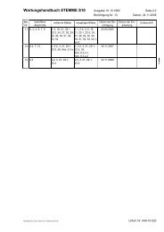
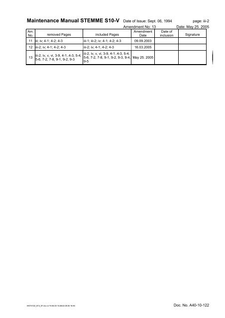
<strong>Maintenance</strong> <strong>Manual</strong> <strong>STEMME</strong> <strong>S10</strong>-V <strong>Date</strong> <strong>of</strong> <strong>Issue</strong>: Sept. 06, 1994 page: iii-2<br />
Amendment No: 13 <strong>Date</strong>: May 25. 2005<br />
Am.<br />
No. removed Pages included Pages<br />
Amendment<br />
<strong>Date</strong><br />
<strong>Date</strong> <strong>of</strong><br />
inclusion Signature<br />
11 iii; iv; 4-1; 4-2; 4-3 iii-1; iii-2; iv; 4-1; 4-2; 4-3 09.09.2003<br />
12 iii-2; iv; 4-1; 4-2; 4-3 iii-2; iv; 4-1; 4-2; 4-3 16.03.2005<br />
13<br />
iii-2, iv, v, vi, 3-9, 4-1..4-3, 5-4,<br />
5-6, 7-2, 7-8, 9-1, 9-2, 9-3<br />
iii-2, iv, v, vi, 3-9, 4-1..4-3, 5-4,<br />
5-6, 7-2, 7-8, 9-1, 9-2, 9-3, 9-4,<br />
9-5<br />
May 25. 2005<br />
A4010122_B13_97.doc-iv/14.06.05 10:26/22.08.05 16:48 Doc. No. A40-10-122
<strong>Maintenance</strong> <strong>Manual</strong> <strong>STEMME</strong> <strong>S10</strong>-V <strong>Date</strong> <strong>of</strong> <strong>Issue</strong>: Sept. 06, 1994 page: iv<br />
Amendment No:13 <strong>Date</strong>: May 25, 2005<br />
0.3 List <strong>of</strong> Effective Pages<br />
This record is valid for the Serial No. specified on the title page. Changes on the <strong>Maintenance</strong> <strong>Manual</strong> are<br />
included ex works if dated before production inspection. Amendments concerning alternative equipment is<br />
provided only if mentioned on page 1. Following amendments must be added by hand.<br />
page am. no. date<br />
i 9 Dec. 12,2001<br />
ii -<br />
iii-1 11 Sep. 09,2003<br />
iii-2 13 May 25,2005<br />
iv 13 May 25,2005<br />
v 13 May 25,2005<br />
vi 13 May 25,2005<br />
1-1 -<br />
2-1 -<br />
2-2 7 Nov. 11,1999<br />
3-1 -<br />
3-2 5 Feb. 22,1999<br />
3-3 5 Feb. 22,1999<br />
3-4 -<br />
3-5 7 Nov. 11,1999<br />
3-6 9 Dec. 12,2001<br />
3-7 7 Nov. 11,1999<br />
3-8 -<br />
3-9 13 May 25,2005<br />
3-10 7 Nov. 11,1999<br />
4-1 13 May 25,2005<br />
4-2 13 May 25,2005<br />
4-3 13 May 25,2005<br />
5-1 5 Feb. 22,1999<br />
5-2 5 Feb. 22,1999<br />
5-3 5 Feb. 22,1999<br />
5-4 13 May 25,2005<br />
5-5 4 Aug. 08,1996<br />
5-6 13 May 25,2005<br />
5-7 7 Nov. 11,1999<br />
6-1 -<br />
6-2 -<br />
6-3 -<br />
6-4 -<br />
6-5 7 Nov. 11,1999<br />
6-6 7 Nov. 11,1999<br />
7-1 7 Nov. 11,1999<br />
7-2 13 May 25,2005<br />
7-3 -<br />
page am. no. date<br />
7-4 7 Nov. 11,1999<br />
7-5.1 7 Nov. 11,1999<br />
7-5.2 7 Nov. 11,1999<br />
7-6 7 Nov. 11,1999<br />
7-7.1 7 Nov. 11,1999<br />
7-7.2 7 Nov. 11,1999<br />
7-8 13 May 25,2005<br />
7-9 7 Nov. 11,1999<br />
7-10 -<br />
7-11 5 Feb. 22,1999<br />
8-1 3 Oct. 25,1995<br />
8-2 3 Oct. 25,1995<br />
8-3 -<br />
8-4 5 Feb. 22,1999<br />
8-5 -<br />
8-6 3 Oct. 25,1995<br />
8-7 -<br />
8-8<br />
8-9<br />
5 Feb. 22,1999<br />
9-1 13 May 25,2005<br />
9-2 13 May 25,2005<br />
9-3 13 May 25,2005<br />
9-4 13 May 25,2005<br />
9-5 13 May 25,2005<br />
10-1 1 Dec. 10,1994<br />
11-1 7 Nov. 11,1999<br />
12-1 -<br />
12-2 -<br />
12-3.1 5 Feb. 22,1999<br />
12-3.2 5 Feb. 22,1999<br />
12-4.1 5 Feb. 22,1999<br />
12-4.2 5 Feb. 22,1999<br />
12-5.1 5 Feb. 22,1999<br />
12-5.2 5 Feb. 22,1999<br />
12-6.1 5 Feb. 22,1999<br />
12-6.2 5 Feb. 22,1999<br />
12-7.1 5 Feb. 22,1999<br />
12-7.2 5 Feb. 22,1999<br />
page am. no. date<br />
12-8.1 5 Feb. 22,1999<br />
12-8.2 5 Feb. 22,1999<br />
12-9.1 9 Dec. 12,2001<br />
12-9.2 5 Feb. 22,1999<br />
12-10 7 Nov. 11,1999<br />
12-11 -<br />
12-12 3 Oct. 25,1995<br />
12-13.1 7 Nov. 11,1999<br />
12-13.2 7 Nov. 11,1999<br />
12-13.3 7 Nov. 11,1999<br />
12-14 -<br />
12-15 -<br />
12-16 -<br />
12-17 -<br />
12-18 -<br />
12-19 3 Oct. 25,1995<br />
12-20 -<br />
12-21 -<br />
12-22 -<br />
12-23 9 Dec. 12,2001<br />
12-24 -<br />
12-25 -<br />
12-26 -<br />
12-27 -<br />
12-28 -<br />
12-29 -<br />
12-30 -<br />
title page<br />
Annex A<br />
title page<br />
Annex B<br />
title page<br />
Annex C<br />
7 Nov. 11,1999<br />
7 Nov. 11,1999<br />
A4010122_B13_97.doc-iv/14.06.05 10:26/22.08.05 16:48 Doc. No. A40-10-122<br />
-
<strong>Maintenance</strong> <strong>Manual</strong> <strong>STEMME</strong> <strong>S10</strong>-V <strong>Date</strong> <strong>of</strong> <strong>Issue</strong>: Sept. 06, 1994 page: v<br />
Amendment No.: 13 <strong>Date</strong>: May 25, 2005<br />
0.4 Contents<br />
0.1 Deviations from the Basic <strong>Maintenance</strong> <strong>Manual</strong> for the Model: ii<br />
0.2 Record <strong>of</strong> Amendments iii<br />
0.3 List <strong>of</strong> Effective Pages iv<br />
0.4 Contents v<br />
1. General Remarks on <strong>Maintenance</strong> 1-1<br />
2. Brief Description and Technical Data 2-1<br />
3. Description <strong>of</strong> Assemblies 3-1<br />
3.1 Cell, Primary and Secondary Structures 3-1<br />
3.1.1 Wing 3-1<br />
3.1.2 Fuselage and Cockpit 3-1<br />
3.1.3 Tail Unit 3-3<br />
3.2 Control System 3-3<br />
3.3 Power Plant (figure 3.3) 3-5<br />
3.3.1 Engine 3-5<br />
3.3.2 Fuel system (fig. 3.3.2.a) 3-5<br />
3.3.3 Lubrication System 3-6<br />
3.3.4 Cooling System 3-6<br />
3.3.5 Induction System 3-6<br />
3.3.6 Exhaust System 3-6<br />
3.3.7 Power-Plant Controls and Instruments 3-6<br />
3.3.8 Fire Protection 3-7<br />
3.3.9 Engine Cowlings 3-7<br />
3.3.10 Propeller 3-7<br />
3.3.11 Drivetrain System 3-9<br />
3.4 Landing Gear 3-9<br />
3.4.1 Main Landing Gear (figure 3.4.1) 3-9<br />
3.4.2 Tail Wheel 3-10<br />
3.5 Flight Instruments, Pressure System (figure 3.5.a) 3-10<br />
3.6 Electrical System (figures 3.6.a, b, c, d, e and 3.6.f) 3-10<br />
3.7 Communication and Navigation Equipment 3-12<br />
3.8 Oxygen Equipment 3-12<br />
4. Airworthiness Limitations Section 4-1<br />
5. Checks 5-1<br />
5.1 Pre-Flight Checks 5-1<br />
5.2 Periodical Checks, Inspection Lists 5-1<br />
5.3 Check Lists for Periodical Inspections 5-1<br />
5.3.1 Wing 5-1<br />
5.3.2 Fuselage Front Section 5-2<br />
5.3.3 Cockpit 5-2<br />
5.3.4 Center Section <strong>of</strong> Fuselage 5-3<br />
5.3.5 Tail Boom 5-3<br />
5.3.6 Empennage 5-3<br />
5.3.7 Powerplant - except Propeller and Drivetrain System 5-4<br />
5.3.8 Propeller 5-5<br />
5.3.9 Drivetrain System 5-5<br />
5.3.10 Main Landing Gear 5-6<br />
5.3.11 Tail Wheel 5-6<br />
5.3.12 Flight Instruments and Pressure System 5-6<br />
5.3.13 Electrical System 5-6<br />
5.3.14 Radio and Navigation Equipment 5-6<br />
5.3.15 Oxygen System 5-7<br />
5.3.16 Completition works 5-7<br />
A4010122_B13_97.doc-v/14.06.05 10:26/22.08.05 16:49 Doc. No. A40-10-122
<strong>Maintenance</strong> <strong>Manual</strong> <strong>STEMME</strong> <strong>S10</strong>-V <strong>Date</strong> <strong>of</strong> <strong>Issue</strong>: Sept. 06, 1994 page: vi<br />
Amendment No.: 13 <strong>Date</strong>: May 25, 2005<br />
5.4 Special Inspections 5-7<br />
5.4.1 Inspection following an Impact Landing or a Wing Tip Landing 5-7<br />
5.4.2 Inspection following an Impact to the rotating Propeller 5-7<br />
6. <strong>Maintenance</strong> Instructions, Tolerances, Adjustment Data for the Aircraft 6-1<br />
6.1 General Information 6-1<br />
6.2 Ground Towing, Supporting Points, and Lifting <strong>of</strong> Aircraft<br />
6.3 Determination <strong>of</strong> the Empty Weight and Corresponding Center <strong>of</strong> Gravity; Information on Weight<br />
6-1<br />
Limits 6-1<br />
6.4 Control System 6-4<br />
6.4.1 Deflection <strong>of</strong> Control Surfaces, Control System Friction, and Pilot Forces 6-4<br />
6.4.2 Masses and Moments <strong>of</strong> the Control Surfaces 6-4<br />
6.4.3 Slackness <strong>of</strong> Control System Bearings 6-5<br />
6.5 Lubrication Chart 6-5<br />
6.6 Tightening Moments for Screw Joints<br />
7. <strong>Maintenance</strong> Instructions, Tolerances, Adjustment Data for Assemblies /<br />
6-5<br />
Equipment 7-1<br />
7.1 Airframe 7-1<br />
7.1.1 Wing 7-1<br />
7.1.2 Fuselage and Cockpit 7-1<br />
7.1.3 Tail Unit 7-2<br />
7.2 Control System 7-2<br />
7.3 Powerplant 7-2<br />
7.3.1 Engine 7-2<br />
7.3.2 Fuel System 7-2<br />
7.3.3 Oil System 7-3<br />
7.3.4 Cooling System 7-3<br />
7.3.5 Induction System 7-3<br />
7.3.6 Controls/Instruments 7-3<br />
7.3.7 Fire Protection 7-3<br />
7.3.8 Engine Cowlings 7-3<br />
7.3.9 Propeller 7-3<br />
7.3.10 Drivetrain System 7-7<br />
7.4 Landing Gear 7-8<br />
7.4.1 Main Landing Gear 7-8<br />
7.4.2 Tail Wheel 7-10<br />
7.5 Flight Control Instruments and Pitot and Static Pressure System 7-10<br />
7.6 Electrical System 7-10<br />
7.7 Radio and Navigation Equipment 7-11<br />
7.8 Oxygen Equipment 7-11<br />
8. List <strong>of</strong> cockpit placards and their position 8-1<br />
9. Equipment 9-1<br />
9.1 Minimum Equipment List 9-1<br />
9.2 Supplemental Equipment 9-2<br />
9.3 Additional Equipment and Systems 9-2<br />
9.3.1 Alternative Equipment 9-2<br />
9.3.2 Additional Equipment 9-3<br />
9.3.3 Optional Equipment 9-5<br />
10. List <strong>of</strong> Special Tools 10-1<br />
11. List <strong>of</strong> <strong>Maintenance</strong> Documents for Parts Approved Independently from the<br />
Aircraft 11-1<br />
12. Figures referring to the previous Sections 12-1<br />
Annex A: Supplementary Instructions for <strong>Maintenance</strong> and Care, <strong>Maintenance</strong> Instructions<br />
Annex B: Service Bulletins, Airworthiness Directives<br />
Annex C: Documents (Inspection and Operation Reports)<br />
A4010122_B13_97.doc-vi/14.06.05 10:26/22.08.05 16:52 Doc. No. A40-10-122
<strong>Maintenance</strong> <strong>Manual</strong> <strong>STEMME</strong> <strong>S10</strong>-V <strong>Date</strong> <strong>of</strong> <strong>Issue</strong>. Sept. 06, 1994 page: 3-9<br />
Amendment No.: 13 <strong>Date</strong>: May 25, 2005<br />
Starter: Push-button for the electric starter. This switch is locked if the ignition is turned on<br />
before the starter is activated. After each unsuccessful attempt to start the engine,<br />
the ignition must be switched <strong>of</strong>f first, before the starter can be re-activated.<br />
Ignition: ON / OFF.<br />
The ignition switch connects the Aircraft electrical ground with the magnetos. This<br />
is independent <strong>of</strong> the Master Switch or the Engine Master Switch. When the ignition<br />
is switched ON, the starter solenoid circuit is disconnected by a secondary switch<br />
level in order to prevent damage to the engine and propeller in the event <strong>of</strong><br />
incorrect starting procedures.<br />
Propeller Variable Pitch: TAKE OFF / CRUISE<br />
The cruise setting leads to variable power consumption. The propeller is<br />
disconnected from the electric power source in the TAKE OFF setting <strong>of</strong> when the<br />
landing gear is not retracted, the propeller blades then rotate in the take-<strong>of</strong>f setting.<br />
The take-<strong>of</strong>f setting <strong>of</strong> the propeller blades (not the switch position!) is indicated by<br />
a green light under the switch as soon as the Master Switch and the Engine Master<br />
Switches are ON.<br />
Avionics: to switch "ON" / "OFF" all flight and navigation instruments electrically energized.<br />
During operation <strong>of</strong> the starter, the avionics are switched <strong>of</strong>f or switched over to the<br />
auxiliary battery (if installed).<br />
Avionics supply: Connects the avionics bus to the auxiliary battery instead <strong>of</strong> the main battery. The<br />
following settings are recommended:<br />
-Powered flight: setting: Main battery<br />
-Soaring flight: setting: Auxiliary battery<br />
Landing gear switch: Upper position: gear up<br />
Lower position: gear down<br />
Center position: Circuit disconnected from electrical system.<br />
ACL (optional): ON / OFF - only active when the Engine Master Switch is positioned ON<br />
(Anti-Collision Light, ACL).<br />
Position lights (optional): ON / OFF - only active when the Engine Master Switch is positioned ON.<br />
Auxiliary Battery (optional)<br />
Location: In the upper part <strong>of</strong> the vertical fin or in the left-hand foot-well.<br />
Utilization: Preferably during soaring flight to avoid inadvertently depleting the main battery while<br />
soaring and to ensure sufficient capacity <strong>of</strong> the main battery to re-start the engine.<br />
Switch Positions: The switch AVIONICS SUPPLY switches from the Main to the Auxiliary battery.<br />
Alternatively, automatic switch-over during starter operation or when the main circuit<br />
breaker triggers.<br />
Charging: By the generator during powered flight. Charging via the external plug only charges the<br />
main battery; the auxiliary battery must be charged separately via a direct charger<br />
connection (max. charge voltage is 14.7V).<br />
CAUTION: If the auxiliary battery is removed (but registered in the Equipment List), airworthiness is<br />
lost due to changes in Weight and Balance. The Aircraft cannot be operated until the<br />
Equipment List and Weight and Balance have been corrected.<br />
A4010122_B13_97.doc-3-9/14.06.05 10:26/22.08.05 16:53 Doc. No: A40-10-122
<strong>Maintenance</strong> <strong>Manual</strong> <strong>STEMME</strong> <strong>S10</strong>-V <strong>Date</strong> <strong>of</strong> <strong>Issue</strong>. Sept. 06, 1994 page: 4-1<br />
Amendment No.: 13<br />
LBA-approved<br />
<strong>Date</strong>: May 25, 2005<br />
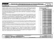
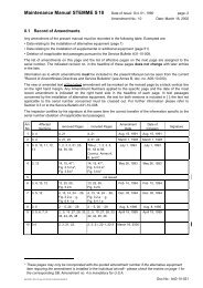
4. Airworthiness Limitations Section<br />
This section is FAA-approved for U.S. registered powered sailplanes in accordance with the provisions <strong>of</strong><br />
14 CFR Section 21.29. In addition, this section is required by FAA Type Certificate No. G 58 EU and it<br />
specifies maintenance required under 14 CFR Sections 43.16 and 91.163 unless an alternative program has<br />
been FAA-approved.<br />
The permissible operating times <strong>of</strong> all parts, components and assemblies assigned for installation - in series<br />
or optional - in the powered sailplane <strong>STEMME</strong> <strong>S10</strong>-V and subject to service life limitations, are notified by<br />
the Service Bulletin no. A31-10-001. When the limitation <strong>of</strong> at least one item changes, this SB will be reissued<br />
in a revised version. The document no. will be maintained in this case, the amendment no. will be advanced<br />
(the letter in the amendment index is for internal use only).<br />
The pages <strong>of</strong> this section are printed on yellow paper for better discernment. They may not be revised without<br />
FAA engineering approval. Regulations upon keeping <strong>of</strong> service records must be observed.<br />
Excerpt <strong>of</strong> Service Bulletin A31-10-001 Amendment-No: 11.a: Review <strong>of</strong> permissible operating times:<br />
No.<br />
<strong>S10</strong><br />
Model Permissible op. time by<br />
<strong>S10</strong>-V<br />
<strong>S10</strong>-VT<br />
Part/Assembly/<br />
Equipment<br />
1 X X X Airframe<br />
(Composite structure)<br />
2 X X Limbach Engine<br />
Manufacturer,<br />
Type<br />
Part No.<br />
(<strong>STEMME</strong>)<br />
Overhaul<br />
(TBO)<br />
Replaceme<br />
nt<br />
NOTES<br />
<strong>STEMME</strong> sundry 6000 h 6000 h (1)<br />
Limbach<br />
L 2400 EB 1.D<br />
L 2400 EB 1.AD<br />
10AM-MOL (2)<br />
3 X X Magneto for Limbach Slick 4230 (from Limbach) (2)<br />
4 X Rotax Engine<br />
5 X<br />
Propeller<br />
(fixed pitch)<br />
ROTAX 914<br />
F2/S1<br />
11AM-M<br />
1000 h<br />
(10 years)<br />
<strong>STEMME</strong> 10AP-N 400 h (3)(4)<br />
6 X Lateral parts <strong>STEMME</strong><br />
10AP-N01<br />
10AP-N11<br />
1000h (4)<br />
7 X Fix-Pitch Propeller <strong>STEMME</strong> 10AP-F 400 h (3) (4)<br />
8 X Centre Part <strong>STEMME</strong> 10AP-F01 2000 h (4)<br />
9 X Variable pitch propeller <strong>STEMME</strong> 10AP-V<br />
200 h<br />
(5 years)<br />
(3)(4)(10)<br />
10 X Variable pitch propeller <strong>STEMME</strong> 11AP-V<br />
200 h<br />
(5 years)<br />
(3)(4)(10)<br />
11 X X Propeller hub <strong>STEMME</strong> 10AP-V01 2000h (4)<br />
12 X<br />
Propeller fork and<br />
X<br />
its fastening<br />
<strong>STEMME</strong><br />
10AP-V88,<br />
-V77, -V78, -VU<br />
400h (3)(4)<br />
13 X X<br />
Reduction Gear<br />
(vee-belts)<br />
<strong>STEMME</strong> 10<strong>AG</strong> 400 h (3)(4)<br />
14<br />
Reduction Gear<br />
X<br />
(cog wheels)<br />
<strong>STEMME</strong> 11<strong>AG</strong> 1000 h (3)(4)<br />
15 X Gear suspension <strong>STEMME</strong> 10AA 1000 h 12 years (4)<br />
16 X Gear suspension <strong>STEMME</strong> 14AA 1000 h 12 years (4)<br />
17 X Gear suspension <strong>STEMME</strong> 11AA 1000 h 12 years (4)<br />
18 X X<br />
Flywheel clutch<br />
(2 flyweights)<br />
<strong>STEMME</strong> 10AK 400 h (3)(4)<br />
19<br />
Flywheel clutch<br />
X<br />
(3 flyweights)<br />
<strong>STEMME</strong> 11AK 400 h (3)(4)<br />
20 X X Driveshaft<br />
Ciba-Geigy<br />
(without P/N ref.)<br />
10AS-07 400 h (3)(4)(9)<br />
21 X X X Driveshaft<br />
Glaenzer-Spicer<br />
19.01.01.xxx<br />
10AS-07 400 h (3)(4)(9)<br />
A4010122_B13_97.doc-4-1/14.06.05 10:26/22.08.05 16:54 Doc. No: A40-10-122<br />
(8)
<strong>Maintenance</strong> <strong>Manual</strong> <strong>STEMME</strong> <strong>S10</strong>-V <strong>Date</strong> <strong>of</strong> <strong>Issue</strong>. Sept. 06, 1994 page: 4-2<br />
Amendment No.: 13<br />
LBA-approved<br />
<strong>Date</strong>: May 25, 2005<br />
Model Permissible op. time by<br />
No.<br />
<strong>S10</strong><br />
<strong>S10</strong>-V<br />
<strong>S10</strong>-VT<br />
Part/Assembly/<br />
Equipment<br />
Manufacturer,<br />
Type<br />
Part No.<br />
(<strong>STEMME</strong>)<br />
Overhaul<br />
(TBO)<br />
Replaceme<br />
nt<br />
NOTES<br />
22 X X X Driveshaft<br />
MAN Techn. <strong>AG</strong><br />
95.0700.00.000<br />
10AS-W 400 h (3)(4)(9)<br />
23 X X X Driveshaft <strong>STEMME</strong> 10AS-F 400 h (3)(4)(9)<br />
24<br />
rubber parts <strong>of</strong> the<br />
X<br />
engine<br />
Rotax sundry 5 years (7)<br />
25<br />
Differential fuel<br />
X<br />
pressure sensor<br />
<strong>STEMME</strong> 11AB-K01 5 years<br />
26 X X<br />
Rubber parts <strong>of</strong> the<br />
X<br />
gear suspension<br />
<strong>STEMME</strong> sundry 12 years<br />
27 X X<br />
Rubber parts <strong>of</strong> the<br />
clutch<br />
<strong>STEMME</strong><br />
10AK-43<br />
10AK-48<br />
12 years<br />
28 X X<br />
flexible disk <strong>of</strong> the drive<br />
shaft system<br />
<strong>STEMME</strong> 10AS-09 12 years<br />
29<br />
flexible disk <strong>of</strong> the drive<br />
X<br />
shaft system<br />
<strong>STEMME</strong> 11AS-09 12 years<br />
30 X X Fuel Hoses <strong>STEMME</strong> 10AB-... - 5 years<br />
31 X X Fuel Hoses <strong>STEMME</strong> HZ-KSL 014 - 5 years<br />
32 X X X Fuel Hoses <strong>STEMME</strong> HZ-KSL010 - 5 years<br />
33 X X Lubrication Hoses <strong>STEMME</strong> 10AM-KÖS / ~T - 5 years<br />
34 X Lubrication Hoses <strong>STEMME</strong> 11AM-O... - 5 years<br />
35 X Coolant Hoses <strong>STEMME</strong> 11AM-W... - 5 years<br />
36 X X X Brake Hoses sundry 10FO-B06 - 10 years<br />
37 X X X Safety Harnesses sundry 10C-08/-09 - 12 years (6)<br />
38 X X<br />
Control Rod<br />
X<br />
Connectors<br />
L'Hotellier 10M-098/-099 (2)<br />
On expiry <strong>of</strong> a part’s permissible operating times the affected part has to be sent to the manufacturer for<br />
inspection. The manufacturer has to decide if further use is possible after the inspection, or if an replacement<br />
or overhaul or repair is necessary.<br />
If the limitation is given in operating hours and in a calendar period (year), the first occurring case applies.<br />
If further equipment subject to service life limitations is installed, the overhaul intervals and service life limits<br />
prescribed by the respective manufacturer must be observed. The item has to be entered in the form Review<br />
<strong>of</strong> Operating times.<br />
A4010122_B13_97.doc-4-2/14.06.05 10:26/22.08.05 16:55 Doc. No: A40-10-122
<strong>Maintenance</strong> <strong>Manual</strong> <strong>STEMME</strong> <strong>S10</strong>-V <strong>Date</strong> <strong>of</strong> <strong>Issue</strong>: Sept. 06, 1994 page: 5-4<br />
Amendment No.: 13 <strong>Date</strong>: May 25, 2005<br />
Type and Subject <strong>of</strong> Inspection first<br />
25<br />
7. Inspect Horizontal Stabilizer rear fitting for wear <strong>of</strong> pins/bushings, fatigue<br />
cracks (especially in the vicinity <strong>of</strong> welding and cutouts in the fixing plates),<br />
axial and radial clearance, corrosion.<br />
Inspection after [h]<br />
every<br />
50<br />
every<br />
100<br />
A4010122_B13_97.doc-5-4/14.06.05 10:26/22.08.05 16:56 Doc. No: A40-10-122<br />
AI<br />
X X X<br />
8. Check tight fit <strong>of</strong> all bolt connections <strong>of</strong> both HS fittings. X X X<br />
9. Check bolt connection <strong>of</strong> elevator push-pull rod to rear HS fitting. X X X<br />
10. Check HS fittings for slackness after attaching the HS (section 7.1.3). X X X<br />
11. Inspect HS and elevator for damage and cracks, look out for signs <strong>of</strong> hidden<br />
structural damage. Check drain outlets.<br />
12. Check deflection <strong>of</strong> rudder and elevator (for Control Surface adjustment data,<br />
see section 12)<br />
X X<br />
X X<br />
5.3.7 Powerplant – except Propeller and Drivetrain System<br />
The hours given in this list are engine operating hours.<br />
Caution: In excess <strong>of</strong> the inspections listed below, the instructions <strong>of</strong> the engine manufacturer<br />
given in the Engine Operating and <strong>Maintenance</strong> <strong>Manual</strong> are mandatory. LIMBACH<br />
prescribes an additional periodical engine check after every 25 operating hours.<br />
1. Check engine mounting X X<br />
2. Check fuel lines and fittings for leak tightness (fuel leakage) X X X<br />
3. Check conditions <strong>of</strong> fuel lines (in particular cracks in the outer surface) X X X<br />
4. Check function <strong>of</strong> the electric fuel pumps. X X<br />
5. Exchange fine filters, clean coarse filters (in tank connector at the wing root;<br />
open clamp on wing side and remove finger strainer)<br />
X X<br />
6. Inspect oil lines, fire protection hose and fittings to oil cooler and engine for<br />
leaks, improper condition (consider service life limit) and looseness. Check<br />
sealing cuff at the left cowling to the oil cooler for proper sealing.<br />
7. Check proper function and settings <strong>of</strong> air inlet flaps, controlled via cowl flap<br />
lever. Settings approx. 2, 2.8, 3.5 in. (5, 7, 9 cm). The flaps must not jam and<br />
fully opened position must be reached safely. Sealing cuff <strong>of</strong> the cooling air<br />
ducts in the side cowling must be in contact with the cooling air box <strong>of</strong> the<br />
engine<br />
8. Inspect flexible hose between the air filters and the carburetors for proper<br />
condition and tight fit.<br />
X X X<br />
X X X X<br />
X X X<br />
9. Check the exhaust system for sealing, cracks and correct attachment X X X<br />
10. Throttle/choke control: make sure that the extreme positions in the carburetors<br />
are achieved. Check attachment <strong>of</strong> control cables and bowden cable casings.<br />
Check condition <strong>of</strong> return springs on the carburetors.<br />
X X X<br />
11. Functional check <strong>of</strong> engine instruments X X X<br />
12. Check fire wall steel sheets for proper condition and tight fit. X X X
<strong>Maintenance</strong> <strong>Manual</strong> <strong>STEMME</strong> <strong>S10</strong>-V <strong>Date</strong> <strong>of</strong> <strong>Issue</strong>: Sept. 06, 1994 page: 5-6<br />
Amendment No.: 13 <strong>Date</strong>: May 25, 2005<br />
Inspection after [h]<br />
Type and Subject <strong>of</strong> Inspection first<br />
25<br />
5.3.10 Main Landing Gear<br />
1. Inspect the main landing gear legs and trailing arms for deformation and<br />
possible cracks as an result <strong>of</strong> overloads<br />
every<br />
50<br />
every<br />
100<br />
A4010122_B13_97.doc-5-6/14.06.05 10:26/22.08.05 16:56 Doc. No: A40-10-122<br />
AI<br />
X X X X<br />
2. Check the linear actuators for external damages. X X X<br />
3. Inspect the screw joint <strong>of</strong> the complete landing gear X X X<br />
4. Check main landing gear tires for poor condition and creep markings. Tire<br />
pressure: [45 - 48 p.s.i. (3.1 - 3.3 bar)] 5s [36 - 39 p.s.i. (2.5 - 2.7 bar), if optional<br />
wide tires installed] 5a<br />
X X X X<br />
5. Functional check <strong>of</strong> trailing arm spring suspension. X X X<br />
6. Wheel bearings: check for ease <strong>of</strong> operation and play. X X X<br />
7. Inspect brake master and wheel cylinders. Check hoses and tubes for proper<br />
guidance, chafe marks and leakage.<br />
X X X<br />
8. Inspect brake discs and brake linings (at least 0.06 in. / 1.5 mm). X X<br />
9. Check brake fluid level (replace fluid once in two years). X X X<br />
10. Check efficiency <strong>of</strong> brakes, adjust brake or vent brake system if required. X X X X<br />
11. Clean and grease hinges <strong>of</strong> landing gear doors. X X<br />
12. Functional check <strong>of</strong> the landing gear (support the Aircraft on trestles); check<br />
stop switches, fit <strong>of</strong> gear doors, bowden cables for emergency release and the<br />
release mechanism on the brace strut.<br />
13. Inspect the operating mechanism <strong>of</strong> the LH landing gear door, including<br />
bowden cable, for improper operation and poor condition.<br />
X X X<br />
X X X<br />
14. Check landing gear position indicator and warning system X X X X<br />
15. Functional check <strong>of</strong> landing gear Emergency Extension Mechanism X X<br />
5.3.11 Tail Wheel<br />
1. Check tail wheel unit for ease <strong>of</strong> operation and play. X X X<br />
2. Check condition <strong>of</strong> tire, pressure (40.6±2.9 p.s.i. / 2.8±0.2 bar) and creep<br />
markings.<br />
X X X X<br />
3. Inspect wheel fork, including bearing. X X X<br />
4. Check spring coupling between tail wheel and rudder. X X X<br />
5.3.12 Flight Instruments and Pressure System<br />
1. Check condition and function - if applicable service life limits - <strong>of</strong> the flight<br />
control instruments (see Equipment List)<br />
X X<br />
2. Check adjustment <strong>of</strong> the stall warning (every second AI) X X<br />
5.3.13 Electrical System<br />
1. Inspect wiring and conduits for improper routing, insecure mounting and<br />
obvious defects <strong>of</strong> electric components.<br />
2. Inspect condition <strong>of</strong> main battery (among others voltage drop during starter<br />
operation).<br />
5.3.14 Radio and Navigation Equipment<br />
1. Inspect radio and navigation equipment for improper installation and insecure<br />
mounting (observe equipment list). Check service life limits if applicable.<br />
X X<br />
X X<br />
X X<br />
2. Check each antenna installed X
<strong>Maintenance</strong> <strong>Manual</strong> <strong>STEMME</strong> <strong>S10</strong>-V <strong>Date</strong> <strong>of</strong> <strong>Issue</strong>: Sept. 06, 1994 page: 7-2<br />
Amendment No.: 13 <strong>Date</strong>: May 25. 2005<br />
7.1.3 Tail Unit<br />
During inspection <strong>of</strong> the horizontal tail mountings, check the backlash <strong>of</strong> the horizontal tail attachment by the<br />
following procedure:<br />
• move horizontal tail tip forward and aft and up and down<br />
• take hold <strong>of</strong> the mid section <strong>of</strong> the horizontal tail fin, push up and down<br />
If excessive backlash is found, the bolts and fittings must be measured. Maximum allowable backlash <strong>of</strong><br />
horizontal tail fittings:<br />
forward fitting: vertically 0.006 in. (0.15 mm) horizontally 0.004 in. (0.1 mm)<br />
rear fitting vertically 0.006 in. (0.15 mm) horizontally 0.006 in. (0.15 mm)<br />
7.2 Control System<br />
Position <strong>of</strong> stops <strong>of</strong> the control systems: see description in section 3.2<br />
Adjustment data: see fig. 6.4.1.<br />
7.3 Powerplant<br />
7.3.1 Engine<br />
<strong>Maintenance</strong> <strong>of</strong> the engine in accordance with the instructions <strong>of</strong> the Operating and <strong>Maintenance</strong> <strong>Manual</strong> for<br />
Flight Engines "Limbach L 2400 and Series".<br />
Adjustment <strong>of</strong> the carburetors: For access from the top, remove cover in the upper fire wall.<br />
Access to the fuel pump: Remove cover in the upper fire wall.<br />
Access to the mounting attachment <strong>of</strong> accessories (generator, magneto): remove lateral and lower engine<br />
cowlings.<br />
Removal <strong>of</strong> Engine:<br />
• disconnect battery<br />
• remove front and rear fire wall sheets<br />
• remove V-supports <strong>of</strong> the frame below the engine<br />
• loosen clutch on engine side and push it forward on the sliding joint (attention: do not lose bushes <strong>of</strong><br />
screw joints).<br />
• remove muffler<br />
• disconnect electrical wiring, fuel hoses above the firewall, bowden cables, oil hoses on the engine and air<br />
induction hoses<br />
• support the engine. Then loosen front engine mount at the attachment to the frame, loosen rear engine<br />
support (attention: mark the distance bushes left/right for reinstallation)<br />
• lower down engine<br />
Installation <strong>of</strong> Engine:<br />
In the opposite order as removal.<br />
7.3.2 Fuel System<br />
Check all fuel lines in the fuel system for tight fit and leak tightness. Check the fuel lines for conditions. A<br />
indication for high wear and the necessary replacement are cracks in the outer surface.<br />
For replacement <strong>of</strong> the fuel hoses after expiration <strong>of</strong> the allowable time in service, remove or lift the upper<br />
parts <strong>of</strong> the fire wall.<br />
A4010122_B13_97.doc-7-2/14.06.05 10:26/22.08.05 17:24 Doc. No: A40-10-122
<strong>Maintenance</strong> <strong>Manual</strong> <strong>STEMME</strong> <strong>S10</strong>-V <strong>Date</strong> <strong>of</strong> <strong>Issue</strong>: Sept. 06, 1994 page: 7-8<br />
Amendment No.: 13 <strong>Date</strong>: May 25. 2005<br />
7.4 Landing Gear<br />
7.4.1 Main Landing Gear<br />
Check the main landing gear legs and the trailing arms for deformations and possible cracks as an result <strong>of</strong><br />
overloads.<br />
Adjustment Data: see fig. 3.4.1.a<br />
Functional Check:<br />
Support the Aircraft (clearance between the main wheels and the ground must be approximately 1.6 in. /<br />
40 mm), remove upper cowling <strong>of</strong> the central fuselage.<br />
Checking procedure:<br />
• Inspect screw joints (torque paint);<br />
• check wheels for smooth turning;<br />
• joint heads <strong>of</strong> the operating arms should not be jammed;<br />
• the articulations <strong>of</strong> the spindles and the operating arms must have play;<br />
• installation <strong>of</strong> the landing gear emergency release system without kinks/collisions;<br />
• landing gear stop switches on the operating arms: check for halfway position and proper functioning,<br />
inspect wiring / connection;<br />
• retraction <strong>of</strong> left landing gear leg:<br />
Check if the landing gear contacts surrounding components,<br />
Brake tube must have regular bends, must not jam.<br />
Stop switch adjustment: 0.08 to 0.2 in. (2 - 5 mm) clearance between the landing gear leg and the shaft<br />
housing.<br />
The stop switch must be positioned in the middle <strong>of</strong> the landing gear strut.<br />
Joint heads <strong>of</strong> the operating arm must not be jammed<br />
Articulation between the spindle and the operating arm must not jam<br />
• extension <strong>of</strong> left landing gear leg:<br />
check if the operating arm returns to its correct over-center-locked position, if necessary adjust the switch.<br />
• retraction <strong>of</strong> right landing gear leg:<br />
(separated from the left side - for this purpose, actuate left stop switch "retracted")<br />
Check if the leg contacts surrounding components.<br />
Brake tube must have regular bends, must not jam.<br />
The stop switch must be positioned in the middle <strong>of</strong> the landing gear strut.<br />
Joint heads <strong>of</strong> the operating arm must not be jammed.<br />
Articulation between the spindle and the operating arm must not jam.<br />
• extension <strong>of</strong> right landing gear leg:<br />
check for correctly over-center-locked position <strong>of</strong> the operating arm.<br />
• retraction <strong>of</strong> both landing gear legs:<br />
Collision check.<br />
Align stop switch on the right landing gear leg for a clearance <strong>of</strong> 0.08 to 0.12 in. (2 - 3 mm) between both<br />
gear legs;<br />
• check <strong>of</strong> landing gear doors:<br />
Smooth operation <strong>of</strong> gear doors<br />
Fit <strong>of</strong> gear doors<br />
Clearance between gear doors and wheels 0.4 to 0.6 in. (10 - 15 mm).<br />
• retract landing gear with the upper cowling <strong>of</strong> the central fuselage mounted:<br />
Check clearance between the drive spindles and the cowling<br />
the bowden cables <strong>of</strong> the emergency release system may not be buckled or get stuck<br />
A4010122_B13_97.doc-7-8/14.06.05 10:26/22.08.05 17:25 Doc. No: A40-10-122
<strong>Maintenance</strong> <strong>Manual</strong> <strong>STEMME</strong> <strong>S10</strong>-V <strong>Date</strong> <strong>of</strong> <strong>Issue</strong>: Sept. 06, 1994 page: 9-1<br />
Amendment No.: 13 <strong>Date</strong>: May 25, 2005<br />
9. Equipment<br />
9.1 Minimum Equipment List<br />
Subject Manufacturer Type TC No., Specification<br />
No.<br />
Range<br />
Airspeed Indicator Winter 6FMS4 T<strong>S10</strong>.210/15 up to 300 km/h<br />
up to 180 mph<br />
up to 160 kts<br />
Winter 6FMS5 T<strong>S10</strong>.210/16 up to 300 km/h<br />
up to 180 mph<br />
up to 160 kts<br />
Winter 7FMS4 T<strong>S10</strong>.210/19 up to 300 km/h<br />
up to 180 mph<br />
up to 160 kts<br />
Winter 7FMS5 T<strong>S10</strong>.210/20 up to 300 km/h<br />
up to 180 mph<br />
up to 160 kts<br />
Altimeter Winter 4FGH10 T<strong>S10</strong>.220/46 up to 10,000 m<br />
up to 30,000 ft<br />
Winter 4FGH20 T<strong>S10</strong>.220/47 up to 10,000 m<br />
up to 30,000 ft<br />
Winter 4FGH40 up to 20,000 ft<br />
Winter 4HM6 T<strong>S10</strong>.220/44 up to 6,000 m<br />
PZL W-12S FD-3/75<br />
Compass Airpath C2300 - -<br />
Stall Warning<br />
System<br />
PZL B-13 FD19/77 -<br />
Ludolph FK16 10.410/3 -<br />
Ludolph FK5 10.410/1 -<br />
Hamilton HI400 TSO C7c Type 1 -<br />
Presesion Aviation<br />
Inc.<br />
PAI-700 TSO<br />
Westerboer Speed Control - -<br />
up to 20,000 ft<br />
Revolution Counter VDO 333.230/009/1 - up to 4000 min -1<br />
Engine hour meter Winter FSZM TS-GW 1510 -<br />
VDO 331.811/010/2 - -<br />
Oil pressure meter VDO 350.271/031/7 - up to 10 bar<br />
Oil temp. meter VDO 310.274/082/1 - up to 150 °C<br />
A4010122_B13_97.doc-9-1/14.06.05 10:26/22.08.05 17:26 Doc. No: A40-10-122
<strong>Maintenance</strong> <strong>Manual</strong> <strong>STEMME</strong> <strong>S10</strong>-V <strong>Date</strong> <strong>of</strong> <strong>Issue</strong>: Sept. 06, 1994 page: 9-2<br />
Amendment No.: 13 <strong>Date</strong>: May 25, 2005<br />
Subject Manufacturer Type TC No., Specification<br />
No.<br />
Range<br />
Fuel contents meter VDO 301.271/036/1 - 0 ··· 4 / 4<br />
Cylinder head<br />
temperature meter<br />
Limbach 170.215/001 - up to 375 °C<br />
Four-element straps Gadringer BaGu 5202 SchuGu<br />
2700<br />
40.070/32<br />
40.071/05<br />
Back-cushion One per seat, compressed 2 in. (50 mm) thick (if no parachute, minimum 2 in. thick, is<br />
used)<br />
9.2 Supplemental Equipment<br />
Depending on operational and environmental conditions, further equipment may be mandatory to<br />
supplementary to the minimum compulsory equipment. The supplementary equipment allowed to be installed<br />
in the <strong>Stemme</strong> <strong>S10</strong>-V is listed in the following selection list.<br />
At the moment, certification is only valid for daytime VFR flights. Flights from 30 min before sunrise and up to<br />
30 min after sunset require lighting equipment, consisting <strong>of</strong> LH and RH navigation lights, tail position light<br />
and anti collision light.<br />
VFR-Night flights are possible after accomplishment <strong>of</strong> the <strong>Stemme</strong> SB A31-10-072.<br />
Subject Manufacturer Type<br />
Lightning system<br />
TC No.,<br />
Specification No.<br />
ACL / Position Lights Whelen / <strong>STEMME</strong><br />
Stern Light Hella / <strong>STEMME</strong><br />
Landing Light Hella / <strong>STEMME</strong><br />
9.3 Additional Equipment and Systems<br />
Range,<br />
Remarks<br />
Different equipment and systems may be installed in the powered glider <strong>S10</strong>, which are not part <strong>of</strong> the<br />
minimum or supplementary equipment and which normally are not series standard. Basically the cases<br />
“Alternative Equipment”, "Additional Equipment" and "Optional Systems" have to be distinguished and treated<br />
differently. For further information please refer to the Service Bulletin A31-10-008.<br />
9.3.1 Alternative Equipment<br />
Special attention is to be paid to the case <strong>of</strong> equipment and systems which are not installed in addition to but<br />
as an alternative to the standard version and thus have an influence on the standard text <strong>of</strong> the <strong>Maintenance</strong><br />
<strong>Manual</strong>. Here the rule applies that associated information is added to the corresponding passage <strong>of</strong> the<br />
standard text, with the original text (if any) and the amended text appearing in square brackets each. A<br />
reference number following the closed bracket is identical with the current revision number, the letter<br />
following the reference number indicates whether the text passage applies to the standard version ("s") or to<br />
the alternative version ("a") (example: [···] 3a ).<br />
All text passages in brackets which do not correspond to the aircraft's design configuration<br />
described on page 1 (standard version, if no entries) must be crossed out.<br />
If this procedure cannot be applied (amendments to illustrations), the <strong>STEMME</strong> Company will keep ready<br />
"special versions" <strong>of</strong> the pages concerned identified with the corresponding SB number. In the case <strong>of</strong> an<br />
overall revision, all versions <strong>of</strong> a page will be newly issued; the version applicable to the aircraft concerned is<br />
to be inserted.<br />
A4010122_B13_97.doc-9-2/14.06.05 10:26/22.08.05 17:26 Doc. No: A40-10-122
<strong>Maintenance</strong> <strong>Manual</strong> <strong>STEMME</strong> <strong>S10</strong>-V <strong>Date</strong> <strong>of</strong> <strong>Issue</strong>: Sept. 06, 1994 page: 9-3<br />
Amendment No.: 13 <strong>Date</strong>: May 25, 2005<br />
9.3.2 Additional Equipment<br />
In addition to the minimum and supplementary equipment, installation <strong>of</strong> the following devices is allowed. A<br />
precondition is that the energy balance remains within certified limits and the certified weight <strong>of</strong> equipment in<br />
the instrument panel is not exceeded. Altogether 11 kg / 24 lbs instruments, including maximum 1 kg / 2.2 lbs<br />
<strong>of</strong> engine instruments, are certified.<br />
Additionally a ground and flight test must be performed, showing electromagnetic compatibility (EMC).<br />
Changes <strong>of</strong> equipment may be performed by qualified personnel only. An inspector must confirm the correct<br />
installation by an entry in the a/c-logbook, the EMC-test flight, the keeping <strong>of</strong> the energy balance and the<br />
inclusion <strong>of</strong> the changes into the equipment list and the weight and balance report. The above-mentioned<br />
inspection and operation documents must be added to Annex C <strong>of</strong> this <strong>Maintenance</strong> <strong>Manual</strong>.<br />
Subject Manufacturer Type TC No.,<br />
Specification No.<br />
Compass Bohli 46-MFK-1<br />
Range,<br />
Remarks<br />
Mechanical Winter 5StV5 ± 5 m/s<br />
Variometer Winter 5StVM5 ± 1000 ft/min<br />
Bohli 68-PVF-2 ± 10 kts<br />
VHF-COM Becker umpteen<br />
King-Bendix umpteen<br />
Dittel umpteen<br />
Terra umpteen<br />
Intercom PS Engineering<br />
(panel mount)<br />
Transponder/<br />
Encoder<br />
TELEX<br />
(panel mount)<br />
Sigtronics (panel<br />
mount)<br />
Flightcom (panel<br />
mount)<br />
Flightcom (panel<br />
mount)<br />
all models<br />
Pro Com 4<br />
SPA-400 TSO<br />
403-MC<br />
ATC-2<br />
S<strong>of</strong>tcom (portable) ATC-2<br />
Becker ATC-series<br />
Filser TRT-series<br />
Garmin GTX-series<br />
King-Bendix KT-series<br />
Terra TRT 250 D TSO-C74c<br />
Terra AT 3000 TSO-C88<br />
ACK A-30 TSO-C88a<br />
Ameri-King AK-series<br />
Emergency ACK E-01<br />
Transmitter (ELT) Pointer 3000 TSO C91<br />
Part ELT<br />
GPS & Moving Map Garmin all fix installed<br />
NAVITEC MC 3000 System<br />
Skyforce Tracker II<br />
TR 2000<br />
Skyforce Skymap II<br />
SM 2000<br />
CAA L301031<br />
A4010122_B13_97.doc-9-3/14.06.05 10:26/22.08.05 17:26 Doc. No: A40-10-122
<strong>Maintenance</strong> <strong>Manual</strong> <strong>STEMME</strong> <strong>S10</strong>-V <strong>Date</strong> <strong>of</strong> <strong>Issue</strong>: Sept. 06, 1994 page: 9-4<br />
Amendment No.: 13 <strong>Date</strong>: May 25, 2005<br />
Subject Manufacturer Type TC No.,<br />
Specification No.<br />
Skyforce Colour Tracker<br />
CT 2000<br />
Skyforce Colour Skymap<br />
CM 2000<br />
EFIS Dynon Avionics EFIS D-10 System<br />
Electronic Vario, Filser/LX Navigation LX systems<br />
Soaring Computer ILEC SB-8<br />
Collision warning<br />
system<br />
SN-10<br />
Cambridge CAV II<br />
S-NAV<br />
L-NAV<br />
GPS-NAV<br />
300 series<br />
Peschges VP systems<br />
Holltronic Cenfis-system<br />
SDI-Pöschl C4 system<br />
Zs1 System<br />
GP 941<br />
FLARM Technology FLARM<br />
VHF NAV (VOR) Becker NR3301 series<br />
Becker IN 3300 (indicator)<br />
Becker IN 3360 (indicator)<br />
Terra TN 200D<br />
King-Bendix KX125 (COM/NAV) TSO-C37c, -C38c, -<br />
C40c<br />
Horizon LUN LUN 1202<br />
PC Flight systems EGYRO-series<br />
R.C.Allen RCA26AK-4<br />
Turn and Bank Gauting WZ404<br />
Indicator Gauting WZ402/14<br />
Keha 703<br />
Directional Gyro R.C.Allen RCA15AK-2<br />
Range,<br />
Remarks<br />
combined COM/VOR<br />
Fire Warning System <strong>Stemme</strong> Series equipment<br />
Voltmeter/Ammeter Filser SR001 Series equipment<br />
A4010122_B13_97.doc-9-4/14.06.05 10:26/22.08.05 17:27 Doc. No: A40-10-122
<strong>Maintenance</strong> <strong>Manual</strong> <strong>STEMME</strong> <strong>S10</strong>-V <strong>Date</strong> <strong>of</strong> <strong>Issue</strong>: Sept. 06, 1994 page: 9-5<br />
Amendment No.: 13 <strong>Date</strong>: May 25, 2005<br />
9.3.3 Optional Systems<br />
Optional systems are not normally included in the <strong>Maintenance</strong> <strong>Manual</strong>. To each <strong>of</strong> these systems delivered<br />
by <strong>STEMME</strong>, a Service Bulletin approved by the LBA is assigned, providing the information necessary for<br />
correct installation and inspection (e. g. Serial No.'s, Documents, supplementary procedures). If installation<br />
requires additional instructions, an installation instruction is provided. If flight operation requires additional<br />
information, supplements to the Flight <strong>Manual</strong> are provided. Information required for maintained airworthiness<br />
are published as maintenance instructions, to be inserted in the Annex A <strong>of</strong> this <strong>Maintenance</strong> <strong>Manual</strong> and<br />
added to the list <strong>of</strong> maintenance instructions on the cover sheet <strong>of</strong> Annex A.<br />
The document no. Of the Service Bulletin and relevant documents are always identical except for the prefix<br />
(A31- Service Bulletin, A34- Installation Instruction, A36- Flight <strong>Manual</strong> Supplement).<br />
A4010122_B13_97.doc-9-5/14.06.05 10:26/22.08.05 17:27 Doc. No: A40-10-122